EP2017545B1 - Electric heating device - Google Patents
Electric heating device Download PDFInfo
- Publication number
- EP2017545B1 EP2017545B1 EP07014115A EP07014115A EP2017545B1 EP 2017545 B1 EP2017545 B1 EP 2017545B1 EP 07014115 A EP07014115 A EP 07014115A EP 07014115 A EP07014115 A EP 07014115A EP 2017545 B1 EP2017545 B1 EP 2017545B1
- Authority
- EP
- European Patent Office
- Prior art keywords
- housing
- elements
- heating block
- fitting
- heat
- Prior art date
- Legal status (The legal status is an assumption and is not a legal conclusion. Google has not performed a legal analysis and makes no representation as to the accuracy of the status listed.)
- Active
Links
Images


Classifications
-
- F—MECHANICAL ENGINEERING; LIGHTING; HEATING; WEAPONS; BLASTING
- F24—HEATING; RANGES; VENTILATING
- F24H—FLUID HEATERS, e.g. WATER OR AIR HEATERS, HAVING HEAT-GENERATING MEANS, e.g. HEAT PUMPS, IN GENERAL
- F24H3/00—Air heaters
- F24H3/02—Air heaters with forced circulation
- F24H3/04—Air heaters with forced circulation the air being in direct contact with the heating medium, e.g. electric heating element
- F24H3/0405—Air heaters with forced circulation the air being in direct contact with the heating medium, e.g. electric heating element using electric energy supply, e.g. the heating medium being a resistive element; Heating by direct contact, i.e. with resistive elements, electrodes and fins being bonded together without additional element in-between
- F24H3/0429—For vehicles
- F24H3/0435—Structures comprising heat spreading elements in the form of fins
-
- F—MECHANICAL ENGINEERING; LIGHTING; HEATING; WEAPONS; BLASTING
- F24—HEATING; RANGES; VENTILATING
- F24H—FLUID HEATERS, e.g. WATER OR AIR HEATERS, HAVING HEAT-GENERATING MEANS, e.g. HEAT PUMPS, IN GENERAL
- F24H3/00—Air heaters
- F24H3/02—Air heaters with forced circulation
- F24H3/04—Air heaters with forced circulation the air being in direct contact with the heating medium, e.g. electric heating element
- F24H3/0405—Air heaters with forced circulation the air being in direct contact with the heating medium, e.g. electric heating element using electric energy supply, e.g. the heating medium being a resistive element; Heating by direct contact, i.e. with resistive elements, electrodes and fins being bonded together without additional element in-between
- F24H3/0429—For vehicles
- F24H3/0441—Interfaces between the electrodes of a resistive heating element and the power supply means
- F24H3/0447—Forms of the electrode terminals, e.g. tongues or clips
-
- F—MECHANICAL ENGINEERING; LIGHTING; HEATING; WEAPONS; BLASTING
- F24—HEATING; RANGES; VENTILATING
- F24H—FLUID HEATERS, e.g. WATER OR AIR HEATERS, HAVING HEAT-GENERATING MEANS, e.g. HEAT PUMPS, IN GENERAL
- F24H3/00—Air heaters
- F24H3/02—Air heaters with forced circulation
- F24H3/04—Air heaters with forced circulation the air being in direct contact with the heating medium, e.g. electric heating element
- F24H3/0405—Air heaters with forced circulation the air being in direct contact with the heating medium, e.g. electric heating element using electric energy supply, e.g. the heating medium being a resistive element; Heating by direct contact, i.e. with resistive elements, electrodes and fins being bonded together without additional element in-between
- F24H3/0429—For vehicles
- F24H3/0452—Frame constructions
- F24H3/0464—Two-piece frames, e.g. two-shell frames, also including frames as a central body with two covers
-
- F—MECHANICAL ENGINEERING; LIGHTING; HEATING; WEAPONS; BLASTING
- F24—HEATING; RANGES; VENTILATING
- F24H—FLUID HEATERS, e.g. WATER OR AIR HEATERS, HAVING HEAT-GENERATING MEANS, e.g. HEAT PUMPS, IN GENERAL
- F24H3/00—Air heaters
- F24H3/02—Air heaters with forced circulation
- F24H3/04—Air heaters with forced circulation the air being in direct contact with the heating medium, e.g. electric heating element
- F24H3/0405—Air heaters with forced circulation the air being in direct contact with the heating medium, e.g. electric heating element using electric energy supply, e.g. the heating medium being a resistive element; Heating by direct contact, i.e. with resistive elements, electrodes and fins being bonded together without additional element in-between
- F24H3/0429—For vehicles
- F24H3/0452—Frame constructions
- F24H3/0476—Means for putting the electric heaters in the frame under strain, e.g. with springs
-
- F—MECHANICAL ENGINEERING; LIGHTING; HEATING; WEAPONS; BLASTING
- F24—HEATING; RANGES; VENTILATING
- F24H—FLUID HEATERS, e.g. WATER OR AIR HEATERS, HAVING HEAT-GENERATING MEANS, e.g. HEAT PUMPS, IN GENERAL
- F24H9/00—Details
- F24H9/18—Arrangement or mounting of grates or heating means
- F24H9/1854—Arrangement or mounting of grates or heating means for air heaters
- F24H9/1863—Arrangement or mounting of electric heating means
- F24H9/1872—PTC resistor
Definitions
- the present invention relates to an electric heater, which is used in particular as a heater in a motor vehicle for heating air, with a heating block, which is held in an opposite frame opening forming housing and comprises parallel layers of heat-emitting and heat-generating elements.
- Such a heater for air conditioning the interior of a motor vehicle is for example from the EP 1 564 503 known.
- the heat-generating elements of the heating block usually comprise a plurality of one above the other in a plane provided PTC heating elements, which are arranged between conductor tracks, which are usually formed by metal strips. These tracks are energized with different polarity.
- the PTC elements can be glued to these tracks. It is also possible to apply the printed conductors under prestress against the PTC heating elements. In any case, it must be ensured that there is good contact between the conductor tracks and the PTC heating elements for decoupling the heat generated by the PTC heating elements and for coupling in current.
- One or more heat-generating elements may be provided as part of the heating block.
- the heat generated by the heat-generating elements is discharged through heat-emitting elements to the medium to be heated, ie the air.
- the frame openings are usually parallel to each other on opposite sides of a substantially flat, frame-shaped housing.
- the heat-emitting elements are usually formed of meandering bent metal strips that form corrugated fins. These corrugated ribs rest on one or both sides of heat-emitting elements.
- the heating block comprises a plurality of layers of heat-emitting and heat-generating elements, wherein care must also be taken with regard to the heat extraction that the heat-emitting elements abut well on the heat-generating elements.
- the heat-emitting elements can be firmly connected to the heat-generating elements and / or applied by at least one received in the housing spring element under bias.
- the heat-emitting element can also be formed by an extruded aluminum profile which forms webs which extend substantially perpendicular to the layers of the layer structure comprising the heat-emitting and the heat-generating elements.
- the trace i. the generally planar contact surface for the PTC heating element are formed by the outer surface of such an extruded aluminum profile.
- the contact surface for the PTC heating elements are designed to be electrically conductive and electrically connected to the housing usually held in isolation from each other held contacts. In the former case, the contacts are usually formed by the exposed ends of the metal bands.
- the layered heating block of parallel heat-emitting and heat-generating elements, optionally with the addition of one or more parallel thereto extending spring elements is preferably held in a housing having a U-shaped cross-section.
- the frame When loading the layer structure with a spring, the frame should be dimensioned so that the spring force can hold permanently even at the elevated temperatures.
- the insulating frame is nowadays produced not least for economic reasons as an injection molded part.
- Usual housing today consist of a lower housing part and a housing upper part. The lower housing part forms a receptacle for the individual elements of the heating block and, if necessary, the spring element. In this lower housing part, the individual elements of the heating block are arranged.
- the heating block is enclosed by joining the upper housing part and the lower housing part in the housing.
- edges surrounding the frame openings may partially cover the heating block, so that the heating block is enclosed between the frame openings and held in the housing.
- the two housing parts are then connected to each other, for example via a latching connection.
- the housing itself should be as simple as possible.
- the present invention is based on the problem of specifying an electric heater which can be produced more simply and thus more cost-effectively.
- the present invention proposes an electric heater having the features of claim 1. This differs from the generic electric heating device in that the heat-generating elements have fitting elements and these mating elements associated fitting element mounts are formed on the housing and that the mating elements and the associated mating element recordings of different heat-generating elements are designed and matched to each other that the individual heat-generating elements assigned to specific positions within the heating block and can not be used anywhere in the housing.
- an electric heating device is proposed, is specified by special design of individual heat-generating elements by molding individual fitting elements with matching mating element receivers on the side of the housing assignment of individual heat-generating elements to specific positions within the heating block. Accordingly, the individual heat-generating elements of the heating block can not be installed anywhere in the housing. While the position or the positions of certain heat-generating elements is predetermined with corresponding fitting elements within the housing, the heat-emitting elements, for example, each be identically formed, preferably as a meandering bent metal strip identical extent transverse to the layers of the layer structure.
- fitting element in the context of the present invention, in particular parts of the heat-generating elements are considered, which serve no other function than the positioning and / or mounting of these elements in the housing.
- Such otherwise functionless mating elements are formed, for example, positioning elements which hold the PTC heating elements at a predetermined location within the heat-generating element, especially by positioning frames of an insulating material, which form juxtaposed receptacles for each at least one PTC heating element.
- the fitting elements are in this case formed in particular by the ends of the corresponding position frames.
- one end or both ends of the positioning frames can have a specially shaped head, which can be introduced into a receptacle formed on the housing in a corresponding manner.
- a positioning frame may have identical fitting elements at its respective front ends.
- each heat-generating element has matching elements, which differ from the fitting elements of all other heat-generating elements.
- fitting element receptacles are formed on the housing, so that a specific heat-generating element can be installed in the housing only at a predetermined location within the housing.
- the strip conductors forming sheet metal strips may be formed as fitting elements.
- the heat-generating elements comprise metal strips on which the PTC heating elements are electrically conductive and which are brought out of the plane of the associated heat-generating element by bending and passed through slots. which are recessed on the front side of the housing, and that the arcuate metal bands of different heat-generating elements and the associated slots are formed so that the heat-generating elements can not be used anywhere in the housing.
- the ends of selected metal strips which are located in the heating block at the top and bottom of the respective position frame and abut the arranged in the respective position frame PTC heating elements, one or both sides bent at the front end of the heating block, so that the metal strips leave the plane which is taken within the heating block by the corresponding heat-generating element.
- the metal strips at the end of the heating block usually extend at right angles to the layers of the heating block, but after a certain length, i. an offset in this transverse direction bent back into its original orientation and passed through a slot which is recessed end face on the housing, i. usually extends substantially parallel to the layers of the layer structure.
- the length of the offset i. the distance between the slot and the associated heat-generating element can be assigned certain heat-emitting elements to certain positions within the housing, so that the heat-generating elements can not be used anywhere in the housing, but on a specific, preferably on a unique Job.
- the housing comprises a housing lower part, which forms a receptacle for the heating block and a frame surrounding the receptacle and the fitting element receptacles, and an upper housing part, which is connected to the inclusion of the heating block with the housing lower part.
- the fitting element receptacles are in this case designed so that the fitting elements can be inserted into the housing lower part in a direction transverse to the plane in which the heating block extends.
- the individual layers of the heating block are accordingly inserted into the one-sided housing lower part in the direction of the frame opening formed by this housing lower part until it reaches the bottom of the recording.
- the fitting elements of the individual heat-generating elements can be widened in the manner of a hammer head, but be relatively short.
- Other fitting elements may be web-shaped elongated and narrow. It can be provided elongated wide webs, which project beyond the heat generating elements end.
- the fitting elements can be formed in a plan view of the still open housing lower part round, elliptical, H or U-shaped.
- the previously discussed possible cross-sectional shapes are usually integrally formed on the positioning frame and usually connected to a thin web, which connects the fitting elements to the heating block.
- the upper housing part has guide pins which protrude from a cover of the housing upper part enclosing the heating block, are formed integrally therewith and in a corresponding manner thereto the housing lower part recessed pin guides are engaged, wherein the guide pins and the pin guides are formed corresponding to the two housing parts such that the two housing parts are connectable only in a certain orientation with each other.
- the cover may be formed in the manner of a non-specific lid, it is preferable to form the housing upper part specifically and in a specific arrangement with regard to an exact arrangement of parts of the heating block or the spring device Form arrangement for the inclusion of the heating block and for adapting the cover to the shape of the elements of the heating block and a unique is to be attached to the housing lower part.
- the recording and the pin guides forming functional surfaces and the outer contour predetermining contour surfaces of the housing base and the guide pin forming functional surfaces and the limiting boundary surfaces of the housing lower part limiting form only that they extend parallel or perpendicular to the frame opening comprehensive level.
- This embodiment has the advantage that an injection molding tool for the production of lower housing part and upper housing part by means of injection molding of thermoplastics has no undercuts and due to the orthogonal orientation of the functional, contour and boundary surfaces of the housing parts mold surfaces, i. the injection mold can be made in total by means of an end mill in a simple manner. Turning away from complicated injection molds with a spark-eroded, the mold cavity forming mold cavity surface, accordingly, the injection mold for producing the housing of the heater according to the invention can be inexpensively and without special know-how create.
- those surfaces of the housing parts are considered, which limit the receptacle for the heating block, allow the joining of the housing parts and lead the required relative movement of the housing parts.
- those surfaces of the housing parts are considered that define the outer contour of the housing parts and the housing as a whole. Relatively narrow end faces or edge surfaces on which two flat surfaces abut one another at right angles do not count as corresponding functional, contour and edge surfaces Boundary surfaces in the sense of the invention. These faces and edge surfaces may be rounded or chamfered.
- the housing is usually formed in this preferred embodiment as a rectangular member which surrounds a substantially also substantially rectangular receptacle for the heating block and on its two outer sides in each case also defines a likewise substantially rectangular housing opening.
- the lower housing part has for this purpose a parallel to the corresponding housing opening extending contact surface, which also forms a functional surface in the sense of development and against which the heating block is applied after insertion into the lower housing part.
- the pin guides are exposed on the opposite side of the lower housing part. These pin guides are formed in at least one of the spars, preferably on the opposite longitudinal beams of a frame member of the housing base, which surrounds the heating block circumferentially and includes in it. This frame element forms the majority of the housing base. Only in the region of the frame opening, which is formed by an end face of the frame member, extending struts, the receiving opening and enforce between the outside of the housing and the heating block are provided after it is inserted into the lower housing part.
- the upper housing part consists essentially of a cover which extends the other, parallel to the frame opening formed by the frame member and is likewise interspersed with struts, preferably corresponding to the struts of the housing lower part.
- This cover is a substantially flat component with only parallel or orthogonal to the frame opening of the upper part extending surfaces. From the inward surface of the cover protrude the guide pins, which accordingly extend web-shaped perpendicular to the plane containing the frame opening. Preferably, these guide pins are predominantly, if not exclusively provided on the long sides.
- both transverse sides of the housing upper part may further be provided a pin which cooperates with a corresponding thereto formed on the lower housing part recess, which is missing on the opposite transverse side of the housing base, so that the upper housing part makes sense only in a certain orientation with the lower housing part can be connected.
- the housing of the electric heater of the present invention preferably consists solely of the two housing parts, i. Upper housing part and lower housing part. By welding, gluing or clipping on a front side of the housing, which is surmounted by electrical connection elements, a mounting flange and / or a control housing for controlling the heating block can be attached. These additional components are usually not part of the housing of the electric heater according to the invention.
- Their housing has a flat, simple, rectangular, box-shaped outer contour in a simplified embodiment.
- the lower housing part usually forms the receptacle for the heating block. If this is held under spring preload in the housing, it is proposed according to a preferred embodiment of the present invention that the lower housing part forms contact surfaces for the at least one spring element with which the heating block can be held under pretension in the receptacle. These contact surfaces extend only parallel or perpendicular to the plane surrounding the frame opening. It usually extend those contact surfaces for the spring element, which resist the spring force, strictly perpendicular to the plane which also contains the frame opening. In addition, and in a relatively small extent, one or more abutment surfaces are furthermore provided as abutment surfaces for the at least one spring element, against which the spring element abuts, after it has been inserted into the housing lower part. The stop surfaces thus provide the lowest position of the spring element in the lower housing part.
- selected guide pins are designed as latching pins.
- a surface of the latching pin which extends parallel to the movement of the joining of the lower housing part and the upper housing part lies in that plane which also encompasses the other guide surfaces of the latching journal.
- the locking pin also serves to guide the relative movement when joining the lower housing part and the upper housing part.
- the latching pin for connecting housing upper part and housing lower part opens with its latching surface in a window, which is formed on the outside of the housing base, namely where the associated pin guide opens.
- the latching surface of the latching pin also extends with respect to an easy production of the injection-molded plastic housing parallel to the plane that the Frame opening includes.
- a corresponding extension has the latching counter surface formed by the window.
- a latching ridge of the latching pin projecting beyond the latching surface goes off from the outer surface of the cover and in a bulge which is formed on the outer edge of the cover.
- the latching web preferably extends from the plane containing the frame opening up to the latching surface and parallel to the guide surfaces of the guide pins.
- the preferred development of the present invention allows a simple machining, for example, with an end mill and the locking pin-forming tool surface of the injection mold.
- a bulge in this embodiment is preferably to understand a contour that jumps from the cover circumferentially surrounding forehead separation surface or edge side inwards and at least in the region of the detent surface dominated by the outer surface of the detent web.
- all surfaces of the two housing parts extend exclusively parallel or perpendicular to a plane containing the frame opening.
- the frame opening is used as the reference plane, this takes place in view of the knowledge that the frame opening forms the bottom of an injection mold for forming a lower housing part or upper part and, in any case, lies parallel to the parting plane of the injection mold.
- the reference to the frame opening means at the same time a reference to the parting plane of the injection mold.
- Only edge surfaces between surfaces meeting at right angles or end faces of housing parts can be chamfered or rounded off according to a preferred embodiment of the present invention by milling or grinding the injection molding tools that demould the edge or end faces.
- These end faces include, for example, the end faces of the guide pins, d. H. in the insertion direction front surface of the corresponding guide pin or at the respective ends formed end faces of the guide pins which extend parallel to the insertion direction.
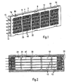
- the Fig. 1 shows a perspective side view of an embodiment of the electric heater with a housing 2, consisting of a lower housing part 4 and an upper housing part 6. Both housing parts 4, 6 are positively connected to each other and take in a heating block 8, which arranged from a plurality of parallel layers to each other heat-generating elements 10 and heat-emitting elements 12 exists.
- the heat-emitting elements 12 are formed as corrugated rib elements of meandering bent sheet metal strip.
- contact tongues 15 are arranged one above the other in the transverse direction.
- the contact tongues pass through recesses 16 which are recessed on the housing 2 and which in each case receive a contact tongue and are predominantly formed by the housing lower part 4, but are completed at one end face by the housing upper part 6.
- the housing 2 has two opposite frame openings, of which in Fig. 1 only the frame opening 16 formed by the upper housing part 6 can be seen.
- the frame opening formed by the lower housing part 4 is in Fig. 4 and identified by reference numeral 18.
- the frame openings 16, 18 are each interspersed with struts 20 which extend at right angles to the layers of the heating block 8 and connect the opposing longitudinal beams of the lower housing part 4 and upper housing part 8 with each other.
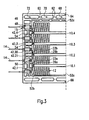
- the Fig. 2 shows details of the heating block 8 and its inclusion in particular in the lower housing part 4 and shows the lower housing part 4 in a plan view with the housing upper part removed.
- the heat-emitting elements 12 are only incompletely shown at the respective front ends of the housing lower part 4. Accordingly, the illustration in Fig. 2 also a view of the frame opening 18 formed by the lower housing part 4 free.
- the exemplary embodiment shown has four heat-generating elements 10, which are each accommodated in the housing lower part 4 in an insulating manner and with a certain mobility transverse to the layers of the layer structure (heating block 8).
- the lower housing part 4 has for this purpose fitting element receptacles 22 which open a receptacle 24, which is formed essentially by the housing lower part 4 and accommodates the heating block 8.
- fitting element receptacles 22a, 22b are provided in the exemplary embodiment shown (cf. Fig. 3 ).
- the heat-generating elements 10 have at their front ends fitting elements 26a, 26b which respectively fit only in the corresponding corresponding fitting element receptacle 22a or 22b.
- the corresponding fitting element receptacles 22 are matched to the fitting elements 26 provided corresponding thereto, that the heat generating elements 10 are movable by a few tenths of a millimeter transverse to the longitudinal extent of the layers of the heating block 8 in the housing 2.
- the outer fitting elements 26a are designed as a hammer head and engage in correspondingly formed fitting element receptacles 22a.
- the fitting elements 26b associated with these elongated fitting element receptacles 22b are rod-shaped and less wide than the hammer-head-like fitting elements 26a. Due to this particular configuration, the central heat-generating elements 10 do not fit in the outer positions for heat-generating elements 10 of the heating block. In a corresponding manner, the outer heat-generating elements can not be arranged in the middle of the heating block, ie insert into the housing 2.
- the heat-generating elements 10 can not be used anywhere in the housing 2, the heat-emitting corrugated fin elements 12 are nonspecific and as lengths of a meandering curved first sheet metal strip as manufactured and cut from this continuous material to length. Each individual heat-emitting element 12 can be used at any position for a heat-emitting element within the heating block 8.
- the fitting elements 26 are integrally formed on a positioning frame 28, which in the 6 and 7 can be seen and explained in more detail below with reference to these figures.
- the positioning frame 28 is made of an insulating material and serves for the positioning of PTC heating elements 30.
- a receptacle 32 in the positioning frame 28 is recessed for each individual PTC heating element 30, which surrounds this PTC heating element and thus defines it.
- sheet metal strips 34, 36 which form electrical conductors for energizing the PTC heating elements 30 and via which the heat generated by the PTC heating elements to the heat-emitting elements 12 is passed by heat transfer. These lie directly on the metal bands 34, 36 at.
- the front ends of the positioning frame 28 are extended over a fitting element web 38 on the position of the metal strips 34, 36 addition.
- the respective fitting elements 26 of the positioning frame 28 At the outer end of the fitting element webs 38 are the respective fitting elements 26 of the positioning frame 28.
- the vast extent of the position frame 28 in the width direction of the respective metal bands 34, 36 occupied.
- the positioning frame on holding webs 40 which are provided immediately adjacent to the lateral edge of the metal strips 34, 36 and the corresponding metal strips 34, 36 project beyond the top and these overlap on the outside, preferably with the tracks 34, 36 in contact and abut this.
- the holding webs 40 are formed in the embodiment shown in one piece by way of injection molding initially as a right angle to the main extension direction of the position frame 28 outgoing projections.
- the distance of opposing projections is selected so that the sheet metal strip 34 or 36 just fits between these projections.
- the one-piece component thus produced by injection molding is then provided with the essential parts of the heat-generating element 10, i. the PTC heating elements 30 are inserted into the corresponding receptacle 32 and surrounded on both sides by the metal strips 34, 36. Thereafter, the projections are plastically deformed inwardly and so the interconnects 34, 36 formed across.
- a hot forming is used, in which the holding webs 40 forming material locally in the area of the metal strips 34, 36 warms up and thus softened.
- the means used in each case can locally heat the position frame 28, for example by means of hot air or by heat conduction.
- the heating effecting agent is preferably formed by a tool which simultaneously performs the transformation of the retaining webs 40.
- the holding webs 40 are not continuous in the longitudinal direction of the heat-generating element 10, but are provided in sections 40.1 to 40.5. These sections 40.1 to 40.5 leave between them a passage 41 free, which is designed such that in each case a strut 22 in the width direction between the sections 40.1; 40.2; 40.3; 40.4 or 40.5 fits.
- the section formed by the passage 41 in any case, projects inwards in relation to the outer surface of the retaining webs 40 to such an extent that at least half the thickness of the struts 22 fits between the retaining webs 40 and is accommodated there.
- the struts 22 and the positioning frame 28 may also be referred to as the first strut, and the retaining webs 40, which may be referred to as the second strut 43.
- the heat-generating element 10 is formed as a preassembled component and can thus be handled during assembly, without the risk that the conductor tracks 34, 36 or even the inserted in the position frame 28 PTC heating elements 30 are lost. It should be noted, however, that usually the holding webs only fix the metal strips 34, 36 in the position frame, but not with a contact force against the PTC heating elements 30 put, which is sufficient to energize the PTC heating elements 30 during operation safe. This is in any case effected in the embodiment discussed in the context of the present invention by a spring element, which will be described below with reference to the Fig. 8 to 10 will be explained in more detail.
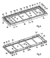
- Fig. 3 and 6 are a metal strip, namely in Fig. 6 shown sheet metal strip 34, bent out of the plane of the heat generating element 10. Accordingly, an offset 42 results between the plane in which the sheet metal strip 34 abuts against the PTC heating elements 30, and a free end 44, which by repeated, but opposite bending extends parallel to the first-mentioned main portion of the sheet metal strip 34. Again Fig. 3 can be seen, this free end 44 is mechanically and electrically connected by a crimp 46 to the associated contact tongue 14.
- upper heat-emitting elements have an outgoing from the upper sheet metal strip 34 offset 42.3 and 42.4.
- the lower heat generating element 10.1 has a downwardly outgoing offset 42.1.
- the metal strips 34, 36 of the heat generating element 10 marked with reference numeral 10.2 are on both sides to form an offset 42.20 or 42.21 arc and each provided with a contact tongue 14. Due to these differences, it is possible to avoid exchanging the positions for the heat-generating elements 10.3 and 10.2 within the housing 2.
- the embodiment allows that the two middle heat-generating elements 10.2 and 10.3 can be interchanged with one another due to the design of contact tongue receivers 48. A corresponding interchangeability is also given for the two outer heat-generating elements 10.1 and 10.4.
- the lower housing part 4 can be molded in an injection mold that can be produced cost-effectively, since all areas significant for the housing 4 extend parallel or at right angles to the frame opening 18 of the housing lower part 4.
- the lower housing part 4 initially substantially mutually perpendicular frame surfaces 52a-d, which surround the heating block 8 circumferentially and perpendicular to the plane containing the frame opening 18 includes.
- the corresponding frame surface 52b opens outward via four fitting element web receivers 54 whose main walls likewise extend at right angles to the plane containing the frame opening 18.
- a corresponding extension have those functional surfaces of the housing lower part 4, which form the contact tongue receptacle 48 and the here leading slots 15 and 50 substantially and those walls which limit the fitting element receptacle 22 and in Fig. 3 are shown.
- the receptacles 15, 22, 50 and 54 described above are bounded on the side of the lower housing part 4 by a bottom which runs parallel to the plane containing the frame opening 18 of the housing lower part 4.
- This receiving floor is in Fig. 4 designated by reference numeral 56.
- This bottom 56 also forms the inner surface of the struts 22 and edge-side stops 58, 60 for the yet to be explained spring element on the one hand and for the located on the opposite longitudinal side outer heat-emitting element 12 on the other.
- These stops 58 and 60 in turn are parallel to the plane which also contains the frame opening 18.
- a pin guide 70 which is formed with a relatively short length and opens to a window 74 which lies on the outside of the housing lower part 4.
- the pin guide 68 Adjacent to this central pin guide 70, the pin guide 68 is provided, each extending over about 1/3 of the length of the longitudinal bars 64, 66.
- pin guides 70 At the outer end of these pin guides 68 are in turn pin guides 70 with associated windows 74, as described above.
- At the front ends of the longitudinal beams 64, 66 turn relatively small pin guides 72 are formed, which extend from the inner surface of the longitudinal bars 64, 66 to the outer surface of the housing base, which also includes the frame opening 18.
- the functional surfaces forming the pin guides 68, 70, 72 all extend at right angles to the plane containing the frame opening 18. Only the front edges of the corresponding openings 68 to 72 are slightly chamfered or rounded in order to facilitate the insertion of corresponding guide pins 76 to 80 of the upper housing part 6. To facilitate connection of the lower housing part 4 and the upper housing part, the free ends of the walls are further chamfered or rounded, which delimit the spacers 62 and the receptacles 22b, 15, 50, 48 at the end and form the upper ends of the spacers 62.
- FIG. 5 shown in perspective housing upper part 6 also has only orthogonal or parallel to the corresponding housing opening 16 aligned functional and boundary surfaces.
- the guide surfaces of the previously mentioned guide pins 76, 78, 80 are provided as functional surfaces, which can be introduced into the corresponding pin guides 68, 70, 72.
- the guide pins 78 are formed as latching pins and form latching webs 82, which are surmounted on the upper side by a thickened head of the latching pin 78, which form a latching surface 86 which extends parallel to the plane which also contains the frame opening 16.
- the latching webs 82 are derived from the top of a cover 88, which as substantially planar component is formed and the frame opening 16 defines and further includes the outer surface of the struts 22.
- the cover 88 is formed frame-shaped as a cover for the lower housing part 4. Accordingly, the guide pin 76 to 80 from the inside of the cover 88 are perpendicular from.
- a bulge 90 is provided for the locking webs 82. In the area of the bulge 90, the edge surface of the cover 88 is retracted inwards, so that the flat planar side surface of the latching web 82 extends parallel to the guide surfaces of the guide pins 76 and 80, but inwardly to the respective outer guide surface of these guide pins 76, 80th lies.
- the heating block 8 facing inner surfaces of the corresponding guide pins 78 to 80 are, however, in a plane.
- a further guide pin 92 is provided, which cooperates with a corresponding thereto recessed on the lower housing part 4 further guide recess 94, but does not fit into the fitting element receptacles 22 and the Reeds 48, so that it is ensured that the upper housing part 6 in dismissstimmter and clearly placed on the lower housing part 4 and joined with this.
- the walls surrounding the further pin guide 94 and forming the guide pin 92 also extend at right angles to the plane lying on the frame opening 16 or 18.
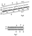
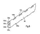
- the Fig. 8 shows a perspective side view of a spring element 96, which rests against the edge of the heating block 8 and is in its installed position at the height of the heating block 8.
- front side of the spring element 96 forms a flat contact surface 98, at which the adjacent, in Fig. 3 uppermost heat-emitting element rests with its lamellae. More precisely, the ends, which are bent over at the ends, lie more meandering lamellae of the corrugated ribbed strip 12 against this contact surface 98.
- the abutment surface 98 is formed by a first flat sheet metal strip on which both sides transverse outgoing leg spring 100 have been formed by punching, which are initially within the plane of the contact surface 98 and after punching by bending in the as in the Fig. 8 . 10 . 11 and 12 recognizable shape have been brought.
- Two spring legs 100o, 100u lie in the width direction, ie transversely to the longitudinal extent of the planar contact surface 98th and thus in the insertion direction of the spring element 96 during assembly above the other.
- Each individual spring limb 100o, 100u forms an inclined sliding surface 102a, 102b, 102c, which in each case enclose an angle of between 35 and 55 °, preferably of approximately 45 °, between itself and the planar contact surface.
- Between the longitudinal direction of the spring element 96 successively provided pairs of spring legs 100 are flat segments 104, in which the spring element 96 is formed as a rectangular flat sheet metal strip.
- spring element 96 has pairs of spring legs 100o , 100u corresponding to the number of spaces between the individual spacers 62 on the longitudinal spar 64 (see. Fig. 4 ).
- Each pair of spring legs 100o , 100u is in the installed position of the spring element 96 between these spacers 62.
- the flat segment 104 bridges the width of the spacers 62 and connects adjacent spring leg pairs 100o, 100u together.
- the correspondingly produced spring can thus be introduced as a one-piece component into the housing 2, in particular in the housing lower part 4, which simplifies the production of the electrical heating device.
- the wall portions of the frame surface 42c provided between adjacent spacers 62 accordingly form a support surface 106 for the respective pairs of spring legs 100.
- the spring element 96 Due to the vote of the spring element 100, especially the configuration of the flat segments 104 between the pairs of superposed spring legs 100, it is not possible to introduce the spring element 96 in the wrong orientation in the lower housing part 4.
- the spring element 96 can only be moved into its installed position, in which the spring element is accommodated at the level of the heating block 8 in the housing 2, when the flat contact surface 98 is aligned with the heating block.
- the heating block is held by the spacers 62 at a distance from the support surfaces 106, so that the spring element 96 can be applied to these surfaces at any time and without interference from the heating block 8 when inserted into the housing base 4.
- the spring element 96 With a progressive insertion movement of the spring element 96 in the direction of the heating block 8, ie with progressive introduction into the heating block, the spring element 96 is then forced urgently due to the spring force through the lower spring leg 100u in the direction of the heating block 8, so that the layers 10, 12th of the heating block are compressed.
- the flat contact surface 98 then already has such an overlap with the adjacent heat-emitting element 12, that with progressive Einbringterrorism the spring element 96 is guided sufficiently in the direction of insertion between the heating block 8 and the lower housing part 4.
- the housing-side counterforce is formed by an upper edge 108 which is formed between the support surface 106 and the inner surface of the longitudinal beam 64 through the joint of the two surfaces.
- the housing 2 has a further housing element, which cooperates with the spring element 96.
- This further housing element is formed by an edge 110 of the housing top 6, which is formed between the inner surface of the cover 88 and a bottom 112 of the housing top 6, by the abutting edge of an outer edge 113 defining the bottom 112 of the housing top with the inner surface the cover 88.
- the height offset between this bottom 112 and the inner surface of the cover 88 takes into account the fact that the heating block 8 projects beyond the surface formed by the longitudinal bars 64, 66 surface 63, approximately the same length as the spacers 62nd the inner surface 63 of the longitudinal bars 64, 66 projects beyond.
- the edge 110 abuts an inclined sliding surface 102a of the spring element 96, which is formed by the upper spring leg 100o.
- Fig. 10 and 12a it can be seen, is the upper end of the spring element 96 in a substantially pressure-free state at a distance from the bottom 112 of the upper housing part. 6
- the individual layers 10, 12 are introduced into the lower housing part 4. Thereafter, the spring element 96 is manually inserted a little way into the lower housing part, at least until the layers of the heating block 8 against each other and the spring element 96 is provided sufficiently deep between the heating block 6 and the frame surface 52c.
- the guide pins 76, 78, 80, 92 in this case engage in the corresponding pin guides 68, 70, 72, 94 a.
- the spring element 96 initially remains essentially free of tension. In this state, a sufficient overlap between the guide pin and the corresponding recesses can already be achieved, so that the two housing parts 4, 6 can be displaced relative to one another only in a linear direction. Thereafter, the joining of the housing parts 4, 6 under application of the spring force.
- the spring legs 100o, 100u are slightly compressed until the bottom 112 of the upper housing part 6 abuts against the upper end of the spring element 96 (see. Fig. 12b ).
- the two edges 108 and 100 have already slid over a certain distance along the inclined sliding surfaces 102a and 102b.
- the upper spring leg 100o is already elastically bent inwards so that, as the insertion movement progresses, the free end of the leg 100o, which forms a further inclined sliding surface 102c in the center of the spring element 96, can pass the edge 108 reliably. Thereafter, a progressive joining movement between the two housing parts 4, 6 also leads to the entrainment of the spring element 96.
- the spring element 96 has reached its end position when the two housing parts 4, 6 abut each other with their respective surfaces facing each other.
- the spring element 96 is clamped and held in this installation position due to the spring tension between the heating block 8 and the frame surface 52c. If the spring element 96th is displaced by an unintentional force from the outside, prevents in each case the stop 58 and the bottom 112 of the upper housing part 6, that the spring element 96 is forced out of the housing 2.
- the spring element is brought into its installation position by closing the lower housing part and the upper housing part when closing the housing, in which the spring element is at the height of the heating block, i. is arranged in the plane which is also occupied by the heating block. Furthermore, the spring element is placed under spring preload only during insertion, and that only when the two housing parts 4, 6 are guided by positive engagement of the guide pins 76 to 80 in the corresponding pin guides 68, 70, 72 relative to each other.
- the structural design accordingly offers the possibility of stress-free to introduce the components of the heating block in the housing 24 formed by the housing 2. Only then is the spring tension, and in fact adjacent to each other and within limits against each other positioned housing parts 4, 6.
- a spring element may be provided, which has a spring leg, which is initially substantially free of tension in the installed position. This spring element is introduced stress-free together with the heating block in the receptacle 24.
- the spring element has a spring leg, the spring leg forms in the direction of the stop 58 outwardly and downwardly inclined sliding surface forms, for a pin which cooperates with the spring element and the corresponding spring leg during joining set of housing upper part and lower housing part under spring bias, so that the spring element is applied in total against the heating block 8 under spring bias.
- the spring element is initially taken free of stress together with the heating block in the lower housing part and remains stationary when generating the spring preload relative to the joining direction.
- the spring element is slightly displaced only in the plane of the heating block and applied to the heating block.
- the or the spring leg is pivoted to produce the elastic bias.
- the particular design of the heat generating elements 10 allows for easier assembly, since the grid assembly formed by the first and second struts 20, 43 is not completely part of the housing, but the second struts are formed with the frame 28 and thus is located where the PTC heating elements 30 come to rest within the heating block 8.
- housing parts can be produced accordingly, which are relatively simple.
- the heat-emitting element 12 is prepared as a preassembled unit and further ensured by the fitting elements 26 and the associated receptacles 22 that the heat-generating elements 12 can be installed only at predetermined locations within the housing 2, the manufacture of the electric heater, in particular the assembly of the items also be done by less experienced staff.
- the specific embodiment of the embodiment provides an unambiguous assignment of different components of the electric heater. If this clear assignment is not met, the components of the electric heater can not be mounted.
Landscapes
- Engineering & Computer Science (AREA)
- Physics & Mathematics (AREA)
- Thermal Sciences (AREA)
- Chemical & Material Sciences (AREA)
- Combustion & Propulsion (AREA)
- Mechanical Engineering (AREA)
- General Engineering & Computer Science (AREA)
- Resistance Heating (AREA)
- Air-Conditioning For Vehicles (AREA)
- Direct Air Heating By Heater Or Combustion Gas (AREA)
Description
Die vorliegende Erfindung betrifft eine elektrische Heizvorrichtung, welche insbesondere als Zuheizer in einem Kraftfahrzeug zur Erwärmung von Luft zum Einsatz kommt, mit einem Heizblock, welcher in einem gegenüberliegende Rahmenöffnung ausbildenden Gehäuse gehalten ist und parallele Lagen von wärmeabgebenden und wärmeerzeugenden Elementen umfasst.The present invention relates to an electric heater, which is used in particular as a heater in a motor vehicle for heating air, with a heating block, which is held in an opposite frame opening forming housing and comprises parallel layers of heat-emitting and heat-generating elements.
Ein solcher Zuheizer zur Klimatisierung des Innenraums eines Kraftfahrzeuges ist beispielsweise aus der
Es können ein oder mehrere wärmeerzeugende Elemente als Teil des Heizblocks vorgesehen sein. Die von den wärmeerzeugenden Elementen erzeugte Wärme wird über wärmeabgebende Elemente an das zu erwärmende Medium, d.h. die Luft abgegeben. Diese durchströmt das Gehäuse durch die beiden Rahmenöffnungen, die zwischen sich den ebenen Heizblock aufnehmen. Die Rahmenöffnungen liegen dabei üblicherweise parallel zueinander an gegenüberliegenden Seiten eines im Wesentlichen flachen, rahmenförmigen Gehäuses. Im Hinblick auf eine möglichst kostengünstige Herstellung der elektrischen Heizvorrichtung werden die wärmeabgebenden Elemente in der Regel aus mäandrierend gebogenen Blechstreifen gebildet, die Wellrippen ausbilden. Diese Wellrippen liegen ein- oder beidseitig an wärmeabgebenden Elementen an. Dementsprechend umfasst der Heizblock mehrere Lage von wärmeabgebenden und wärmeerzeugenden Elementen, wobei auch im Hinblick auf die Wärmeauskopplung darauf zu achten ist, dass die wärmeabgebenden Elemente gut an den wärmeerzeugenden Elementen anliegen. Auch hierzu können die wärmeabgebenden Elemente mit den wärmeerzeugenden Elementen fest verbunden und/oder durch wenigstens ein in dem Gehäuse aufgenommenes Federelement unter Vorspannung angelegt werden.One or more heat-generating elements may be provided as part of the heating block. The heat generated by the heat-generating elements is discharged through heat-emitting elements to the medium to be heated, ie the air. This flows through the housing through the two frame openings, which receive the flat heating block between them. The frame openings are usually parallel to each other on opposite sides of a substantially flat, frame-shaped housing. With a view to the most cost-effective production of the electric heater, the heat-emitting elements are usually formed of meandering bent metal strips that form corrugated fins. These corrugated ribs rest on one or both sides of heat-emitting elements. Accordingly, the heating block comprises a plurality of layers of heat-emitting and heat-generating elements, wherein care must also be taken with regard to the heat extraction that the heat-emitting elements abut well on the heat-generating elements. Also for this purpose, the heat-emitting elements can be firmly connected to the heat-generating elements and / or applied by at least one received in the housing spring element under bias.
Statt durch eine mäandrierendes Blechband kann das wärmeabgebende Element auch durch ein stranggepresstes Aluminiumprofil gebildet sein, welches Stege ausbildet, die sich im Wesentlichen rechtwinklig zu den Lagen des Schichtaufbaus, umfassend die wärmeabgebenden und die wärmeerzeugenden Elemente erstrecken. In einem solchen Fall kann die Leiterbahn, d.h. die in der Regel ebene Anlagefläche für das PTC-Heizelement durch die Außenfläche eines solchen stranggepressten Aluminiumprofils gebildet werden. Bei beiden Alternativen Wellrippenelement bzw. Strangpressprofil sind die Anlagefläche für die PTC-Heizelemente elektrisch leitend ausgestaltet und elektrisch mit in dem Gehäuse üblicherweise isoliert voneinander gehaltenen Kontakten verbunden. In dem erstgenannten Fall werden die Kontakte in der Regel durch die freiliegenden Enden der Blechbänder gebildet.Instead of a meandering sheet-metal strip, the heat-emitting element can also be formed by an extruded aluminum profile which forms webs which extend substantially perpendicular to the layers of the layer structure comprising the heat-emitting and the heat-generating elements. In such a case, the trace, i. the generally planar contact surface for the PTC heating element are formed by the outer surface of such an extruded aluminum profile. In both alternatives corrugated fin element or extruded profile, the contact surface for the PTC heating elements are designed to be electrically conductive and electrically connected to the housing usually held in isolation from each other held contacts. In the former case, the contacts are usually formed by the exposed ends of the metal bands.
Der geschichtete Heizblock aus parallelen wärmeabgebenden und wärmeerzeugenden Elementen, gegebenenfalls unter Hinzufügung eines oder mehrerer sich parallel hierzu erstreckender Federelemente ist vorzugsweise in einem Gehäuse mit einem U-förmigen Querschnitt gehalten. Bei der Beaufschlagung des Schichtaufbaus mit einer Feder ist der Rahmen so zu dimensionieren, dass die Federkraft dauerhaft auch bei den erhöhten Temperaturen halten kann. Dabei ist zu beachten, dass der isolierende Rahmen heutzutage nicht zuletzt aus ökonomischen Gründen als Spritzgussteil hergestellt wird. Übliche Gehäuse bestehen heutzutage aus einem Gehäuseunterteil und einem Gehäuseoberteil. Das Gehäuseunterteil bildet hierbei eine Aufnahme für die einzelnen Elemente des Heizblocks sowie erforderlichenfalls des Federelementes aus. In diesem Gehäuseunterteil werden die einzelnen Elemente des Heizblocks angeordnet. Danach wird der Heizblock durch Fügen von Gehäuseoberteil und Gehäuseunterteil in dem Gehäuse eingeschlossen. Hierzu können Ränder, die die Rahmenöffnungen umgeben, den Heizblock teilweise überdecken, so dass der Heizblock zwischen den Rahmenöffnungen eingeschlossen und in dem Gehäuse gehalten ist. Die beiden Gehäuseteile werden danach miteinander verbunden, beispielsweise über eine Rastverbindung.The layered heating block of parallel heat-emitting and heat-generating elements, optionally with the addition of one or more parallel thereto extending spring elements is preferably held in a housing having a U-shaped cross-section. When loading the layer structure with a spring, the frame should be dimensioned so that the spring force can hold permanently even at the elevated temperatures. It should be noted that the insulating frame is nowadays produced not least for economic reasons as an injection molded part. Usual housing today consist of a lower housing part and a housing upper part. The lower housing part forms a receptacle for the individual elements of the heating block and, if necessary, the spring element. In this lower housing part, the individual elements of the heating block are arranged. Thereafter, the heating block is enclosed by joining the upper housing part and the lower housing part in the housing. For this purpose, edges surrounding the frame openings may partially cover the heating block, so that the heating block is enclosed between the frame openings and held in the housing. The two housing parts are then connected to each other, for example via a latching connection.
Bei dieser Art der Montage stellt sich das Problem, dass die einzelnen Lagen des Heizblocks an vorbestimmter Stelle in dem Gehäuse angeordnet werden müssen. Da nicht jedem wärmeerzeugenden Element eigene Kontakte zugeordnet sind, müssen bei der Montage auch die elektrischen Verhältnisse innerhalb des Heizblocks berücksichtigt werden. Es besteht aber zur Verminderung der Herstellungskosten auch der Wunsch, die Teile des Heizblocks möglichst standardisiert auszubilden, so dass für verschiedene Lagen des Heizblocks identische Bauteile verwendet werden können.In this type of assembly, the problem arises that the individual layers of the heating block must be arranged at a predetermined location in the housing. Since not each heat generating element own contacts are assigned, the electrical conditions within the heating block must be taken into account during assembly. However, in order to reduce the production costs, there is also the desire to design the parts of the heating block as standardized as possible, so that identical components can be used for different positions of the heating block.
Des Weiteren soll im Hinblick auf eine kostengünstige Herstellung der elektrischen Heizvorrichtung das Gehäuse selbst möglichst einfach hergestellt werden können. Dabei sind jedoch auch die besonderen Anforderungen zu beachten, die der Einbau von einem oder mehreren Federelementen in das Gehäuse in der Praxis stellt, wenn beim Fügen der Gehäuseteile der Heizblock bereits in dem Rahmen unter Vorspannung gesetzt ist, so dass das Fügen gegen diese Vorspannung zu erfolgen hat.Furthermore, with regard to cost-effective production of the electric heater, the housing itself should be as simple as possible. However, the special requirements that the installation of one or more spring elements in the housing in practice, if in the joining of the housing parts of the heating block is already set in the frame under bias, so that the joining against this bias to took place.
Im Hinblick auf die zuvor diskutierten Probleme ist bereits mit der
Dieser vorbekannte Vorschlag führt zu einer gewissen Erleichterung bei der Montage, die jedoch voraussetzt, dass die Elemente des Heizblocks wie auch das Federelement in der richtigen Positionierung in das Gehäuseunterteil eingebracht werden. Des Weiteren hat das bei dieser elektrischen Heizvorrichtung verwirklichte Gehäuse verschiedene Schrägflächen, die für das Verspannen und Einschließen des Federelementes beim Fügen der Gehäuseteile erforderlich sind.This prior art proposal leads to a certain ease of assembly, which, however, requires that the elements of the heating block as well as the spring element are placed in the correct position in the lower housing part. Furthermore, the realized in this electric heater housing has different inclined surfaces, which are required for the bracing and enclosing of the spring element when joining the housing parts.
Der vorliegenden Erfindung liegt das Problem zugrunde, eine elektrische Heizvorrichtung anzugeben, die sich einfacher und damit kostengünstiger herstellen lässt.The present invention is based on the problem of specifying an electric heater which can be produced more simply and thus more cost-effectively.
Zur Lösung dieses Problems wird mit der vorliegenden Erfindung eine elektrische Heizvorrichtung mit den Merkmalen von Anspruch 1 vorgeschlagen. Diese unterscheidet sich von der gattungsbildenden elektrischen Heizvorrichtung dadurch, dass die wärmeerzeugenden Elemente Passelemente aufweisen und diesen Passelementen zugeordnete Passelementaufnahmen an dem Gehäuse ausgebildet sind und dass die Passelemente und die zugeordneten Passelementaufnahmen unterschiedlicher wärmeerzeugender Elemente so ausgebildet und aufeinander abgestimmt sind, dass die einzelnen wärmeerzeugenden Elemente zu speziellen Positionen innerhalb des Heizblocks zugeordnet sind und nicht an beliebiger Stelle in das Gehäuse eingesetzt werden können.To solve this problem, the present invention proposes an electric heater having the features of
Mit der vorliegenden Erfindung wird eine elektrische Heizvorrichtung vorgeschlagen, bei der durch spezielle Ausgestaltung einzelner wärmeerzeugender Elemente durch Ausformung individueller Passelemente mit dazu passenden Passelementaufnahmen auf Seiten des Gehäuses eine Zuordnung von einzelnen wärmeerzeugenden Elementen zu speziellen Positionen innerhalb des Heizblocks vorgegeben ist. Die einzelnen wärmeerzeugenden Elemente des Heizblocks können dementsprechend nicht an beliebiger Stelle in dem Gehäuse eingebaut werden. Während die Position bzw. die Positionen bestimmter wärmeerzeugender Elemente mit entsprechenden Passelementen innerhalb des Gehäuses vorgegeben ist, können die wärmeabgebenden Elemente beispielsweise jeweils identisch ausgebildet sein, und zwar vorzugsweise als mäandrierend gebogene Blechstreifen identischer Erstreckung quer zu den Lagen des Schichtaufbaus.With the present invention, an electric heating device is proposed, is specified by special design of individual heat-generating elements by molding individual fitting elements with matching mating element receivers on the side of the housing assignment of individual heat-generating elements to specific positions within the heating block. Accordingly, the individual heat-generating elements of the heating block can not be installed anywhere in the housing. While the position or the positions of certain heat-generating elements is predetermined with corresponding fitting elements within the housing, the heat-emitting elements, for example, each be identically formed, preferably as a meandering bent metal strip identical extent transverse to the layers of the layer structure.
Als Passelement im Sinne der vorliegenden Erfindung werden insbesondere Teile der wärmeerzeugenden Elemente angesehen, die keiner anderen Funktion als die Positionierung und/oder Halterung dieser Elemente in dem Gehäuse dienen. Solche ansonsten funktionslose Passelemente werden beispielsweise Positionselemente gebildet, die die PTC-Heizelemente an vorbestimmter Stelle innerhalb des wärmeerzeugenden Elementes halten, speziell durch Positionsrahmen aus einem isolierenden Material, welche nebeneinander vorgesehene Aufnahmen für jeweils wenigstens ein PTC-Heizelement ausbilden. Die Passelemente werden hierbei insbesondere durch die Enden der entsprechenden Positionsrahmen gebildet. Ein Ende oder beide Enden der Positionsrahmen können hierfür einen speziell ausgeformten Kopf aufweisen, der in eine korrespondierend hierzu ausgebildete Aufnahme an dem Gehäuse eingebracht werden kann. Ein Positionsrahmen kann identische Passelemente an seinen jeweiligen stirnseitigen Enden aufweisen. Diese können aber auch variieren, und zwar so, dass jedes wärmeerzeugende Element Passelemente aufweist, die sich von den Passelementen aller übrigen wärmeerzeugender Elemente unterscheiden. Korrespondierend hierzu sind Passelementaufnahmen an dem Gehäuse ausgeformt, so dass ein bestimmtes wärmeerzeugendes Element in dem Gehäuse lediglich an einer vorbestimmten Stelle innerhalb des Gehäuses eingebaut werden kann. Neben Passelementen, die durch den Positionsrahmen gebildet werden und keine andere Funktion als die Halterung und Positionierung der wärmeerzeugenden Elemente innerhalb des Gehäuses haben, können ferner einzelne, die Leiterbahnen bildende Blechbänder als Passelemente ausgebildet sein.As a fitting element in the context of the present invention, in particular parts of the heat-generating elements are considered, which serve no other function than the positioning and / or mounting of these elements in the housing. Such otherwise functionless mating elements are formed, for example, positioning elements which hold the PTC heating elements at a predetermined location within the heat-generating element, especially by positioning frames of an insulating material, which form juxtaposed receptacles for each at least one PTC heating element. The fitting elements are in this case formed in particular by the ends of the corresponding position frames. For this purpose, one end or both ends of the positioning frames can have a specially shaped head, which can be introduced into a receptacle formed on the housing in a corresponding manner. A positioning frame may have identical fitting elements at its respective front ends. But these can also vary, in such a way that each heat-generating element has matching elements, which differ from the fitting elements of all other heat-generating elements. Corresponding thereto, fitting element receptacles are formed on the housing, so that a specific heat-generating element can be installed in the housing only at a predetermined location within the housing. In addition to fitting elements, which are formed by the position frame and have no function other than the mounting and positioning of the heat-generating elements within the housing, also individual, the strip conductors forming sheet metal strips may be formed as fitting elements.
Im Hinblick darauf wird gemäß einer bevorzugten Ausgestaltung der vorliegenden Erfindung vorgeschlagen, dass die wärmeerzeugenden Elemente Blechbänder umfassen, an denen die PTC-Heizelemente elektrisch leitend anliegen und die stirnseitig des Heizblocks aus der Ebene des zugehörigen wärmeerzeugenden Elementes durch Biegen herausgeführt und durch Schlitze hindurchgeführt sind, die stirnseitig an dem Gehäuse ausgespart sind, und dass die umbogenen Blechbänder unterschiedlicher wärmeerzeugender Elemente und die zugeordneten Schlitze so ausgebildet sind, dass die wärmeerzeugenden Elemente nicht an beliebiger Stelle in das Gehäuse eingesetzt werden können.In view of this, according to a preferred embodiment of the present invention, it is proposed that the heat-generating elements comprise metal strips on which the PTC heating elements are electrically conductive and which are brought out of the plane of the associated heat-generating element by bending and passed through slots. which are recessed on the front side of the housing, and that the arcuate metal bands of different heat-generating elements and the associated slots are formed so that the heat-generating elements can not be used anywhere in the housing.
Bei dieser bevorzugten Ausgestaltung werden die Enden ausgewählter Blechbänder, die sich in dem Heizblock an der Ober- und Unterseite der jeweiligen Positionsrahmen befinden und an den in dem jeweiligen Positionsrahmen angeordneten PTC-Heizelementen anliegen, ein- oder beidseitig an dem stirnseitigen Ende des Heizblockes umgebogen, so dass die Blechbänder die Ebene verlassen, die innerhalb des Heizblocks durch das entsprechende wärmeerzeugende Element eingenommen wird. Die Blechbänder erstrecken sich dementsprechend am Ende des Heizblocks üblicherweise rechtwinklig zu den Lagen des Heizblocks, sind aber nach einer gewissen Länge, d.h. einem Versatz in dieser Querrichtung wieder in ihre ursprüngliche Ausrichtung zurückgebogen und durch einen Schlitz hindurchgeführt, der stirnseitig an dem Gehäuse ausgespart ist, d.h. sich üblicherweise im Wesentlichen parallel zu den Lagen des Schichtaufbaus erstreckt. Durch die Länge des Versatzes, d.h. den Abstand zwischen dem Schlitz und dem zugeordneten wärmeerzeugenden Element kann eine Zuordnung bestimmter wärmeabgebender Elemente zu bestimmten Positionen innerhalb des Gehäuses erreicht werden, so dass die wärmeerzeugenden Elemente nicht an beliebiger Stelle in das Gehäuse eingesetzt werden können, sondern an einer spezifischen, vorzugsweise an einer eindeutigen Stelle.In this preferred embodiment, the ends of selected metal strips, which are located in the heating block at the top and bottom of the respective position frame and abut the arranged in the respective position frame PTC heating elements, one or both sides bent at the front end of the heating block, so that the metal strips leave the plane which is taken within the heating block by the corresponding heat-generating element. Accordingly, the metal strips at the end of the heating block usually extend at right angles to the layers of the heating block, but after a certain length, i. an offset in this transverse direction bent back into its original orientation and passed through a slot which is recessed end face on the housing, i. usually extends substantially parallel to the layers of the layer structure. By the length of the offset, i. the distance between the slot and the associated heat-generating element can be assigned certain heat-emitting elements to certain positions within the housing, so that the heat-generating elements can not be used anywhere in the housing, but on a specific, preferably on a unique Job.
Mit der vorliegenden Erfindung und den zuvor diskutierten Weiterbildungen werden Montagefehler beim Anordnen der einzelnen Lagen des Schichtaufbaus innerhalb des Gehäuses vor dem Fügen der Gehäuseteile vermieden. Bei der erfindungsgemäßen elektrischen Heizvorrichtung sind einzelne Elemente des Heizblocks lediglich an bestimmten Positionen einbaubar. Es ist gänzlich ausgeschlossen, dass die wärmeerzeugenden Elemente an einer Position eingebaut werden, die konstruktiv aufgrund der Ausgestaltung und Zuordnung von Passelement und Passelementaufnahme nicht zugelassen ist. Die Passelemente und die zugeordneten Passelementaufnahmen sind zwar mit gewissem Spiel ausgelegt, so dass die Lagen des Schichtaufbaus trotz der formschlüssigen Aufnahme der Passelemente in den Passelementaufnahmen leicht in diese eingebracht werden können und in der Regel auch zu den Lagen des Heizblocks in Grenzen beweglich gehalten sind. Die Toleranzen sind aber nicht so groß, dass beliebige Passelementaufnahmen beliebige Passelemente aufnehmen können.With the present invention and the developments discussed above assembly errors in arranging the individual layers of the layer structure are avoided within the housing before joining the housing parts. In the electric heater according to the invention, individual elements of the heating block can only be installed at certain positions. It is completely excluded that the heat-generating elements are installed in a position that is structurally not approved due to the design and assignment of fitting element and fitting element holder. Although the mating elements and the associated mating element mounts are indeed designed with a certain play, so that the layers of the layer structure despite the positive reception of the fitting elements in the Passelementaufnahmen can be easily inserted into this and are usually kept movable in the limits of the layers of the heating block. The tolerances are not so great that any fitting element recordings can accommodate any fitting elements.
Gemäß einer bevorzugten Weiterbildung der vorliegenden Erfindung umfasst das Gehäuse ein Gehäuseunterteil, welches eine Aufnahme für den Heizblock und einen die Aufnahme umgebenden Rahmen sowie die Passelementaufnahmen ausbildet, und ein Gehäuseoberteil, welches zum Einschluss des Heizblocks mit dem Gehäuseunterteil verbunden ist. Die Passelementaufnahmen sind hierbei so ausgebildet, dass die Passelemente in einer Richtung quer zu der Ebene, in der sich der Heizblocks erstreckt, in das Gehäuseunterteil einschiebbar sind. Bei der Montage der Heizvorrichtung werden dementsprechend die einzelnen Lagen des Heizblocks in das einseitig offene Gehäuseunterteil in Richtung auf die von diesem Gehäuseunterteil gebildete Rahmenöffnung eingeschoben, bis sie den Boden der Aufnahme erreicht. Die in Einschieberichtung offenen Passelementaufnahmen geben hierbei leicht erkennbar die Position der entsprechenden wärmeerzeugenden Elemente innerhalb des Heizblocks vor. Im Hinblick auf eine eindeutige Zuordnung wird bei dieser bevorzugten Ausgestaltung vorgeschlagen, dass unterschiedliche Passelementaufnahmen in Längsrichtung der wärmeerzeugenden Elemente unterschiedlich lang und/oder in Querrichtung der wärmeerzeugenden Elemente unterschiedlich breit ausgebildet sind.According to a preferred embodiment of the present invention, the housing comprises a housing lower part, which forms a receptacle for the heating block and a frame surrounding the receptacle and the fitting element receptacles, and an upper housing part, which is connected to the inclusion of the heating block with the housing lower part. The fitting element receptacles are in this case designed so that the fitting elements can be inserted into the housing lower part in a direction transverse to the plane in which the heating block extends. When mounting the heater, the individual layers of the heating block are accordingly inserted into the one-sided housing lower part in the direction of the frame opening formed by this housing lower part until it reaches the bottom of the recording. The open in insertion direction fitting element recordings give this easily recognizable the position of the corresponding heat-generating elements within the heating block before. With regard to an unambiguous assignment, it is proposed in this preferred embodiment that different fitting element receptacles are designed to have different widths in the longitudinal direction of the heat-generating elements of different lengths and / or in the transverse direction of the heat-generating elements.
Die Passelemente der einzelnen wärmeerzeugenden Elemente können nach Art eines Hammerkopfes verbreitert, jedoch relativ kurz ausgebildet sein. Andere Passelemente können stegförmig länglich und schmal ausgebildet sein. Es können längliche breite Stege vorgesehen sein, die die wärmeerzeugenden Elemente endseitig überragen. Es sind sehr unterschiedliche Profilierungen denkbar, denen entsprechende Profilierungen auf Seiten der Passelementaufnahmen zugeordnet sind. So können die Passelemente in einer Draufsicht auf das noch offene Gehäuseunterteil rund, elliptisch, H- oder U-förmig ausgebildet sein. Die zuvor diskutierten möglichen Querschnittsformen sind üblicherweise einteilig an dem Positionsrahmen angeformt und üblicherweise mit einem dünnen Steg verbunden, der die Passelemente an den Heizblock anschließt.The fitting elements of the individual heat-generating elements can be widened in the manner of a hammer head, but be relatively short. Other fitting elements may be web-shaped elongated and narrow. It can be provided elongated wide webs, which project beyond the heat generating elements end. There are very different profilings conceivable, which corresponding profiles are assigned on the part of the fitting element receptacles. Thus, the fitting elements can be formed in a plan view of the still open housing lower part round, elliptical, H or U-shaped. The previously discussed possible cross-sectional shapes are usually integrally formed on the positioning frame and usually connected to a thin web, which connects the fitting elements to the heating block.
Zur weiteren Verhinderung von Montagefehlern wird gemäß einer weiteren bevorzugten Ausgestaltung der vorliegenden Erfindung vorgeschlagen, dass das Gehäuseoberteil Führungszapfen aufweist, die von einer den Heizblock einschließenden Abdeckung des Gehäuseoberteils abragen, einstückig mit dieser ausgebildet sind und in korrespondierend dazu an dem Gehäuseunterteil ausgesparten Zapfenführungen in Eingriff sind, wobei die Führungszapfen und die Zapfenführungen derart korrespondierend an den beiden Gehäuseteilen ausgebildet sind, dass die beiden Gehäuseteile lediglich in einer bestimmten Ausrichtung miteinander verbindbar sind. Mit dieser Weiterbildung wird dem Umstand Rechnung getragen, dass zwar die Abdeckung nach Art eines unspezifischen Deckels ausgebildet sein kann, im Hinblick auf eine genaue Anordnung von Teilen des Heizblocks bzw. der Federeinrichtung es jedoch zu bevorzugen ist, auch das Gehäuseoberteil spezifisch auszubilden und in bestimmter Anordnung zum Einschluss des Heizblocks und zur Anpassung der Abdeckung an die Gestalt der Elemente des Heizblocks auszubilden und eine eindeutig an dem Gehäuseunterteil zu befestigen ist.To further prevent assembly errors, it is proposed according to a further preferred embodiment of the present invention that the upper housing part has guide pins which protrude from a cover of the housing upper part enclosing the heating block, are formed integrally therewith and in a corresponding manner thereto the housing lower part recessed pin guides are engaged, wherein the guide pins and the pin guides are formed corresponding to the two housing parts such that the two housing parts are connectable only in a certain orientation with each other. With this development, the fact is taken into account that although the cover may be formed in the manner of a non-specific lid, it is preferable to form the housing upper part specifically and in a specific arrangement with regard to an exact arrangement of parts of the heating block or the spring device Form arrangement for the inclusion of the heating block and for adapting the cover to the shape of the elements of the heating block and a unique is to be attached to the housing lower part.
Im Hinblick auf eine leichte Herstellung der erfindungsgemäßen Heizvorrichtung, insbesondere mit Rücksicht auf eine spritzgießtechnische Herstellung des Gehäuses, wird gemäß einem bevorzugten Aspekt der vorliegenden Erfindung vorgeschlagen, die Aufnahme und die Zapfenführungen bildende Funktionsflächen sowie die äußere Kontur vorgebende Konturflächen des Gehäuseunterteils sowie die Führungszapfen bildende Funktionsflächen und die Abdeckung begrenzende Begrenzungsflächen des Gehäuseunterteils ausschließlich so auszubilden, dass diese parallel oder senkrecht zu der die Rahmenöffnung umfassenden Ebene verlaufen. Diese Ausgestaltung bringt den Vorteil mit sich, dass ein Spritzgießwerkzeug zur Herstellung von Gehäuseunterteil und Gehäuseoberteil im Wege des Spritzguss von Thermoplasten keine Hinterschneidungen aufweist und aufgrund der orthogonalen Ausrichtung der Funktions-, Kontur- und Begrenzungsflächen der Gehäuseteile abformenden Werkzeugflächen, d.h. das Spritzgießwerkzeug insgesamt mittels eines Stirnfräsers auf einfache Weise hergestellt werden kann. In Abkehr von komplizierten Spritzgießwerkzeugen mit einer funkenerodierten, das Formnest ausbildenden Formnestfläche Oberfläche, lässt sich dementsprechend das Spritzgießwerkzeug zur Herstellung des Gehäuses der erfindungsgemäßen Heizvorrichtung kostengünstig und ohne besonderes Know-how erstellen.With regard to an easy manufacture of the heating device according to the invention, in particular with regard to an injection molding production of the housing is proposed according to a preferred aspect of the present invention, the recording and the pin guides forming functional surfaces and the outer contour predetermining contour surfaces of the housing base and the guide pin forming functional surfaces and the limiting boundary surfaces of the housing lower part limiting form only that they extend parallel or perpendicular to the frame opening comprehensive level. This embodiment has the advantage that an injection molding tool for the production of lower housing part and upper housing part by means of injection molding of thermoplastics has no undercuts and due to the orthogonal orientation of the functional, contour and boundary surfaces of the housing parts mold surfaces, i. the injection mold can be made in total by means of an end mill in a simple manner. Turning away from complicated injection molds with a spark-eroded, the mold cavity forming mold cavity surface, accordingly, the injection mold for producing the housing of the heater according to the invention can be inexpensively and without special know-how create.
Als Funktionsflächen im Sinne dieser Weiterbildung werden solche Flächen der Gehäuseteile angesehen, die die Aufnahme für den Heizblock begrenzen, das Fügen der Gehäuseteile erlauben und die hierzu erforderliche Relativbewegung der Gehäuseteile führen. Als Kontur- und Begrenzungsflächen im Sinne dieser Weiterbildung werden solche Flächen der Gehäuseteile angesehen, die die äußere Kontur der Gehäuseteile und des Gehäuses insgesamt definieren. Relativ schmale Stirnseiten bzw. Kantenflächen, an denen zwei ebene Flächen rechtwinklig gegeneinander stoßen, gelten nicht als entsprechende Funktions-, Kontur- und Begrenzungsflächen im Sinne der Erfindung. Diese Stirnflächen und Kantenflächen können abgerundet bzw. angefast sein.As functional surfaces in the sense of this development, those surfaces of the housing parts are considered, which limit the receptacle for the heating block, allow the joining of the housing parts and lead the required relative movement of the housing parts. As contour and boundary surfaces in the sense of this development, those surfaces of the housing parts are considered that define the outer contour of the housing parts and the housing as a whole. Relatively narrow end faces or edge surfaces on which two flat surfaces abut one another at right angles do not count as corresponding functional, contour and edge surfaces Boundary surfaces in the sense of the invention. These faces and edge surfaces may be rounded or chamfered.
Das Gehäuse wird bei dieser bevorzugten Ausgestaltung üblicherweise als rechteckiges Bauteil ausgebildet, welches eine im Wesentlichen ebenfalls im wesentlichen rechteckige Aufnahme für den Heizblock umgibt und an seinen beiden Außenseiten jeweils eine ebenfalls im wesentlichen ebenfalls rechteckige Gehäuseöffnung vorgibt.The housing is usually formed in this preferred embodiment as a rectangular member which surrounds a substantially also substantially rectangular receptacle for the heating block and on its two outer sides in each case also defines a likewise substantially rectangular housing opening.
Das Gehäuseunterteil hat hierzu eine parallel zu der entsprechenden Gehäuseöffnung verlaufende Anlagefläche, die gleichfalls eine Funktionsfläche im Sinne der Weiterbildung ausformt und gegen die der Heizblock nach dem Einschieben in das Gehäuseunterteil angelegt wird. An der gegenüberliegenden Seite des Gehäuseunterteils liegen die Zapfenführungen frei. Diese Zapfenführungen sind in wenigstens einem der Holme, vorzugsweise an den sich gegenüberliegenden Längsholmen eines Rahmenelementes des Gehäuseunterteils ausgeformt, welches den Heizblock umfänglich umgibt und in sich einschließt. Dieses Rahmenelement bildet den überwiegenden Teil des Gehäuseunterteils. Lediglich im Bereich der Rahmenöffnung, die durch eine Stirnfläche des Rahmenelements gebildet wird, erstrecken sich Streben, die Aufnahmeöffnung durchsetzen und zwischen der Außenseite des Gehäuses und dem Heizblock vorgesehen sind, nachdem dieser in das Gehäuseunterteil eingeschoben ist.The lower housing part has for this purpose a parallel to the corresponding housing opening extending contact surface, which also forms a functional surface in the sense of development and against which the heating block is applied after insertion into the lower housing part. On the opposite side of the lower housing part, the pin guides are exposed. These pin guides are formed in at least one of the spars, preferably on the opposite longitudinal beams of a frame member of the housing base, which surrounds the heating block circumferentially and includes in it. This frame element forms the majority of the housing base. Only in the region of the frame opening, which is formed by an end face of the frame member, extending struts, the receiving opening and enforce between the outside of the housing and the heating block are provided after it is inserted into the lower housing part.
Das Gehäuseoberteil besteht im Wesentlichen aus einer Abdeckung, die die andere, sich parallel zu der von dem Rahmenelement gebildeten Rahmenöffnung erstreckt und gleichfalls mit Streben durchsetzt ist, vorzugsweise korrespondierend zu den Streben des Gehäuseunterteils. Diese Abdeckung ist ein im Wesentlichen flaches Bauteil mit lediglich parallel bzw. orthogonal zu der die Rahmenöffnung des Oberteils verlaufenden Oberflächen. Von der inwärtigen Oberfläche der Abdeckung ragen die Führungszapfen ab, die sich dementsprechend stegförmig rechtwinklig zu der Ebene erstrecken, die die Rahmenöffnung enthält. Vorzugsweise sind diese Führungszapfen überwiegend, wenn nicht gar ausschließlich an den Längsseiten vorgesehen. An einer, gegebenenfalls an beiden Querseiten es Gehäuseoberteils kann ferner ein Zapfen vorgesehen sein, der mit einer korrespondierend hierzu an dem Gehäuseunterteil ausgebildeten Ausnehmung zusammenwirkt, die an der gegenüberliegenden Querseite des Gehäuseunterteils fehlt, so dass das Gehäuseoberteil sinnvoll nur in einer bestimmten Ausrichtung mit dem Gehäuseunterteil verbunden werden kann.The upper housing part consists essentially of a cover which extends the other, parallel to the frame opening formed by the frame member and is likewise interspersed with struts, preferably corresponding to the struts of the housing lower part. This cover is a substantially flat component with only parallel or orthogonal to the frame opening of the upper part extending surfaces. From the inward surface of the cover protrude the guide pins, which accordingly extend web-shaped perpendicular to the plane containing the frame opening. Preferably, these guide pins are predominantly, if not exclusively provided on the long sides. At one, optionally on both transverse sides of the housing upper part may further be provided a pin which cooperates with a corresponding thereto formed on the lower housing part recess, which is missing on the opposite transverse side of the housing base, so that the upper housing part makes sense only in a certain orientation with the lower housing part can be connected.
Das Gehäuse der elektrischen Heizvorrichtung der vorliegenden Erfindung besteht vorzugsweise allein aus den beiden Gehäuseteilen, d.h. Gehäuseoberteil und Gehäuseunterteil. Durch Schweißen, Kleben oder Verklipsen kann an einer Stirnseite des Gehäuses, welche von elektrischen Anschlusselementen überragt ist, ein Befestigungsflansch und/oder ein Steuergehäuse zur Ansteuerung des Heizblocks befestigt werden. Diese zusätzlichen Bauteile sind üblicherweise nicht Teil des Gehäuses der erfindungsgemäßen elektrischen Heizvorrichtung. Deren Gehäuse hat bei einer vereinfachten Ausführung eine ebene, einfache, rechteckige, kastenförmige Außenkontur.The housing of the electric heater of the present invention preferably consists solely of the two housing parts, i. Upper housing part and lower housing part. By welding, gluing or clipping on a front side of the housing, which is surmounted by electrical connection elements, a mounting flange and / or a control housing for controlling the heating block can be attached. These additional components are usually not part of the housing of the electric heater according to the invention. Their housing has a flat, simple, rectangular, box-shaped outer contour in a simplified embodiment.
Das Gehäuseunterteil bildet üblicherweise die Aufnahme für den Heizblock aus. Sofern dieser unter Federvorspannung in dem Gehäuse gehalten ist, wird nach einer bevorzugten Weiterbildung der vorliegenden Erfindung vorgeschlagen, dass das Gehäuseunterteil Anlageflächen für das wenigstens eine Federelement ausbildet, mit dem der Heizblock unter Vorspannung in der Aufnahme gehalten werden kann. Diese Anlageflächen erstrecken sich ausschließlich parallel bzw. senkrecht zu der die Rahmenöffnung umfassenden Ebene. Es erstrecken sich üblicherweise diejenigen Anlageflächen für das Federelement, welche die Federkraft widerlagern, streng rechtwinklig zu der Ebene, die auch die Rahmenöffnung enthält. Parallel dazu und in einem relativ geringfügigen Umfang ist ferner eine oder mehrere Anschlagflächen als Anlageflächen für das wenigstens eine Federelement vorgesehen, gegen welche das Federelement anliegt, nachdem dieses in das Gehäuseunterteil eingesetzt worden ist. Die Anschlagflächen geben somit die tiefste Lage des Federelementes in dem Gehäuseunterteils vor.The lower housing part usually forms the receptacle for the heating block. If this is held under spring preload in the housing, it is proposed according to a preferred embodiment of the present invention that the lower housing part forms contact surfaces for the at least one spring element with which the heating block can be held under pretension in the receptacle. These contact surfaces extend only parallel or perpendicular to the plane surrounding the frame opening. It usually extend those contact surfaces for the spring element, which resist the spring force, strictly perpendicular to the plane which also contains the frame opening. In addition, and in a relatively small extent, one or more abutment surfaces are furthermore provided as abutment surfaces for the at least one spring element, against which the spring element abuts, after it has been inserted into the housing lower part. The stop surfaces thus provide the lowest position of the spring element in the lower housing part.
Nach einer weiteren bevorzugten Ausgestaltung der vorliegenden Erfindung sind ausgewählte Führungszapfen als Rastzapfen ausgebildet. Dies bedeutet zunächst, dass sich eine parallel zu der Bewegung des Fügens von Gehäuseunterteil und Gehäuseoberteil erstreckende Fläche des Rastzapfens in derjenigen Ebene liegt, die auch die übrigen Führungsflächen der Rastzapfen umfasst. Der Rastzapfen dient dementsprechend auch der Führung der Relativbewegung beim Fügen von Gehäuseunterteil und Gehäuseoberteil. Gemäß einer Besonderheit der vorliegenden Erfindung mündet der Rastzapfen zur Verbindung von Gehäuseoberteil und Gehäuseunterteil mit seiner Rastfläche in einem Fenster, welches an der Außenseite des Gehäuseunterteils ausgebildet ist, und zwar dort, wo die zugeordnete Zapfenführung mündet. Die Rastfläche des Rastzapfens erstreckt sich auch im Hinblick auf eine leichte Herstellung des spritzgegossenen Kunststoffgehäuses parallel zu der Ebene, die die Rahmenöffnung umfasst. Eine entsprechende Erstreckung weist die durch das Fenster ausgebildete Rastgegenfläche auf.According to a further preferred embodiment of the present invention, selected guide pins are designed as latching pins. This means, first of all, that a surface of the latching pin which extends parallel to the movement of the joining of the lower housing part and the upper housing part lies in that plane which also encompasses the other guide surfaces of the latching journal. Accordingly, the locking pin also serves to guide the relative movement when joining the lower housing part and the upper housing part. According to a special feature of the present invention, the latching pin for connecting housing upper part and housing lower part opens with its latching surface in a window, which is formed on the outside of the housing base, namely where the associated pin guide opens. The latching surface of the latching pin also extends with respect to an easy production of the injection-molded plastic housing parallel to the plane that the Frame opening includes. A corresponding extension has the latching counter surface formed by the window.
Zur weiteren Vereinfachung der Herstellung der Spritzgussform wird gemäß einer weiteren bevorzugten Ausgestaltung der vorliegenden Erfindung vorgeschlagen, dass ein die Rastfläche überragender Raststeg des Rastzapfens von der äußeren Oberfläche der Abdeckung und in einer Ausbuchtung abgeht, die an dem Außenrand der Abdeckung ausgeformt ist. Der Raststeg erstreckt sich hierbei vorzugsweise von der die Rahmenöffnung enthaltenden Ebene bis zu der Rastfläche und parallel zu den Führungsflächen der Führungszapfen. Insofern erlaubt die bevorzugte Weiterbildung der vorliegenden Erfindung eine einfache spanende Bearbeitung beispielsweise mit einem Schaftfräser auch der die Rastzapfen abformenden Werkzeugfläche des Spritzgießwerkzeugs. Als Ausbuchtung ist bei dieser Ausgestaltung vorzugsweise eine Kontur zu verstehen, die von der die Abdeckung umfänglich umgebenden Stirntrennfläche bzw. Randseite nach Innen verspringt und jedenfalls im Bereich der von der Rastfläche überragten Außenfläche des Raststeges liegt.To further simplify the production of the injection mold, it is proposed according to a further preferred embodiment of the present invention that a latching ridge of the latching pin projecting beyond the latching surface goes off from the outer surface of the cover and in a bulge which is formed on the outer edge of the cover. The latching web preferably extends from the plane containing the frame opening up to the latching surface and parallel to the guide surfaces of the guide pins. In this respect, the preferred development of the present invention allows a simple machining, for example, with an end mill and the locking pin-forming tool surface of the injection mold. As a bulge in this embodiment is preferably to understand a contour that jumps from the cover circumferentially surrounding forehead separation surface or edge side inwards and at least in the region of the detent surface dominated by the outer surface of the detent web.
Vorzugsweise erstrecken sich sämtliche Flächen der beiden Gehäuseteile ausschließlich parallel oder senkrecht zu einer Ebene, welche die Rahmenöffnung enthält. Soweit auf die Rahmenöffnung als Bezugsebene abgestellt wird, erfolgt dies im Hinblick auf die Erkenntnis, dass die Rahmenöffnung den Boden einer Spritzgießform zur Ausbildung eines Gehäuseunterteils bzw. eines -oberteils ausformt und jedenfalls parallel zu der Teilungsebene des Spritzgießwerkzeugs liegt. Insofern bedeutet die Bezugnahme auf die Rahmenöffnung gleichzeitig eine Bezugnahme auf die Teilungsebene des Spritzgießwerkzeugs. Lediglich Kantenflächen zwischen rechtwinklig aufeinandertreffenden Flächen bzw. Stirnflächen von Gehäuseteilen können nach einer bevorzugten Ausgestaltung der vorliegenden Erfindung durch Fräsen oder Schleifen der die Kanten- bzw. Stirnflächen abformenden Spritzgießwerkzeuge angefast bzw. abgerundet sein. Zu diesen Stirnflächen gehören beispielsweise die stirnseitigen Endflächen der Führungszapfen, d. h. die sich in Einführrichtung vordere Fläche der entsprechenden Führungszapfen bzw. die an den jeweiligen Enden ausgebildeten Stirnflächen der Führungszapfen, die sich parallel zu der Einführrichtung erstrecken.Preferably, all surfaces of the two housing parts extend exclusively parallel or perpendicular to a plane containing the frame opening. Insofar as the frame opening is used as the reference plane, this takes place in view of the knowledge that the frame opening forms the bottom of an injection mold for forming a lower housing part or upper part and, in any case, lies parallel to the parting plane of the injection mold. In this respect, the reference to the frame opening means at the same time a reference to the parting plane of the injection mold. Only edge surfaces between surfaces meeting at right angles or end faces of housing parts can be chamfered or rounded off according to a preferred embodiment of the present invention by milling or grinding the injection molding tools that demould the edge or end faces. These end faces include, for example, the end faces of the guide pins, d. H. in the insertion direction front surface of the corresponding guide pin or at the respective ends formed end faces of the guide pins which extend parallel to the insertion direction.
Weitere Einzelheiten und Vorteile der vorliegenden Erfindung ergeben sich aus der folgenden Beschreibung eines Ausführungsbeispiels in Verbindung mit der Zeichnung. In dieser zeigen:
- Fig. 1
- eine perspektivische Seitenansicht eines Ausführungsbeispiels der elektrischen Heizvorrichtung;
- Fig. 2
- eine Seitenansicht auf ein Gehäuseunterteil mit darin eingebautem Heizblock des in
Fig. 1 gezeigten Ausführungsbeispiels; - Fig. 3
- einen vergrößerten Ausschnitt der Darstellung gemäß
Fig. 2 ; - Fig. 4
- eine perspektivische Seitenansicht des in den
Fig. 1 bis 3 gezeigten Ausfüh- rungsbeispiels; - Fig. 5
- eine perspektivische Seitenansicht des Gehäuseoberteils der elektrischen Heiz- vorrichtung nach
Fig. 1 ; - Fig. 6
- eine perspektivische Explosionsdarstellung eines wärmeerzeugenden Elementes der elektrischen Heizvorrichtung nach
Fig. 1 ; - Fig. 7
- eine Schnittdarstellung entlang der Linie VII-VII gemäß der Darstellung in
Fig. 6 eines montierten wärmeerzeugenden Elementes; - Fig. 8
- eine perspektivische Seitenansicht eines Federelementes zur Verspannung des Heizblocks des in den
Fig. 1 bis 7 verdeutlichten Ausführungsbeispiels; - Fig. 9
- eine Seitenansicht eines Endes des Beispiels gemäß
Fig. 1 vor dem Fügen der Gehäuseteile; - Fig. 10
- eine Schnittansicht entlang der Linie X-X gemäß der Darstellung in
Fig. 9 ; - Fig. 11
- eine vergrößerte Detailansicht des Ausschnitts A in
Fig. 10 und - Fig. 12a bis e
- vergrößerte Detailansichten ähnlich zu Ansicht gemäß
Figur 11 in verschiede- nen Stadien beim Fügen der Gehäuseteile.
- Fig. 1
- a side perspective view of an embodiment of the electric heater;
- Fig. 2
- a side view of a housing base with built-in heating block of in
Fig. 1 shown embodiment; - Fig. 3
- an enlarged section of the illustration according to
Fig. 2 ; - Fig. 4
- a side perspective view of the in the
Fig. 1 to 3 shown embodiment; - Fig. 5
- a perspective side view of the upper housing part of the electric heating device according to
Fig. 1 ; - Fig. 6
- an exploded perspective view of a heat generating element of the electric heating device according to
Fig. 1 ; - Fig. 7
- a sectional view taken along the line VII-VII as shown in FIG
Fig. 6 a mounted heat generating element; - Fig. 8
- a perspective side view of a spring element for clamping the heating block of the in the
Fig. 1 to 7 illustrated embodiment; - Fig. 9
- a side view of an end of the example according to
Fig. 1 before joining the housing parts; - Fig. 10
- a sectional view taken along line XX as shown in FIG
Fig. 9 ; - Fig. 11
- an enlarged detail view of the section A in
Fig. 10 and - Fig. 12a to e
- enlarged detail views similar to view according to
FIG. 11 in different stages when joining the housing parts.
Die
An einer Stirnseite des Gehäuses 2 wird dieses von fünf in Querrichtung übereinander angeordneten Kontaktzungen 15 überragt. Die Kontaktzungen treten durch an dem Gehäuse 2 ausgesparte Schlitze 16 hindurch, die jeweils für sich eine Kontaktzunge aufnehmen und überwiegend durch das Gehäuseunterteil 4 gebildet sind, jedoch an einer Stirnseite durch das Gehäuseoberteil 6 komplettiert sind.At one end face of the housing 2, this is surmounted by five
Das Gehäuse 2 weist zwei gegenüberliegende Rahmenöffnungen auf, von denen in
Die
Wie zu erkennen, weist das gezeigte Ausführungsbeispiel vier wärmeerzeugende Elemente 10 auf, die jeweils stirnseitig isolierend und mit gewisser Beweglichkeit quer zu den Lagen des Schichtaufbaus (Heizblocks 8) in dem Gehäuseunterteil 4 aufgenommen sind. Das Gehäuseunterteil 4 weist hierzu Passelementaufnahmen 22 auf, die sich einer Aufnahme 24, die im Wesentlichen durch das Gehäuseunterteil 4 gebildet ist und den Heizblock 8 aufnimmt, öffnen. An jeder Stirnseite des Gehäuseunterteils 4 sind bei dem gezeigten Ausführungsbeispiel zwei unterschiedliche Arten von Passelementaufnahmen 22a, 22b vorgesehen (vgl. auch
Während die wärmeerzeugenden Elementen 10 nicht an jeder beliebigen Stelle im Gehäuse 2 eingesetzt werden können, sind die wärmeabgebenden Wellrippenelemente 12 unspezifisch und als Längenabschnitte eines mäandrierend gebogenen zunächst Blechstreifens als gefertigt und von diesem Endlosmaterial auf Länge geschnitten. Jedes einzelne wärmeabgebende Element 12 kann an beliebiger Position für ein wärmeabgebendes Element innerhalb des Heizblocks 8 eingesetzt werden.While the heat-generating
Die Passelemente 26 sind einstückig an einem Positionsrahmen 28 angeformt, der in den
Die stirnseitigen Enden der Positionsrahmen 28 sind über einen Passelementsteg 38 über die Lage der Blechbänder 34, 36 hinaus verlängert. Am äußeren Ende der Passelementstege 38 befinden sich die jeweiligen Passelemente 26 des Positionsrahmens 28. Wie die Querschnittsansicht entlang der in
Das auf diese Weise mittels Spritzgießen hergestellte einteilige Bauteil wird danach mit den wesentlichen Teilen des wärmeerzeugenden Elementes 10 versehen, d.h. die PTC-Heizelemente 30 werden in die korrespondierenden Aufnahme 32 eingelegt und beidseitig von den Blechbändern 34, 36 umgeben. Danach werden die Vorsprünge plastisch nach innen verformt und so die Leiterbahnen 34, 36 übergreifend ausgebildet. Hierbei kommt üblicherweise ein Warmumformen zum Einsatz, bei dem das die Haltestege 40 bildende Material lokal im Bereich der Blechbänder 34, 36 aufwärmt und somit erweicht wird. Das jeweils zum Einsatz kommende Mittel kann beispielsweise mittels Heißluft oder durch Wärmeleitung den Positionsrahmen 28 lokal erwärmen. Im Falle der Erwärmung durch Wärmeleitung wird das die Erwärmung bewirkende Mittel vorzugsweise durch ein Werkzeug gebildet, welches gleichzeitig die Umformung der Haltestege 40 vornimmt.The one-piece component thus produced by injection molding is then provided with the essential parts of the heat-generating
Die Haltestege 40 sind in Längsrichtung des wärmeerzeugenden Elementes 10 nicht durchgängig ausgebildet, sondern sind in Abschnitten 40.1 bis 40.5 vorgesehen. Diese Abschnitte 40.1 bis 40.5 lassen zwischen sich einen Durchgang 41 frei, der derart ausgestaltet ist, dass jeweils eine Strebe 22 in Breitenrichtung zwischen die Abschnitte 40.1; 40.2; 40.3; 40.4 bzw. 40.5 passt. Der durch den Durchgang 41 gebildete Abschnitt verspringt gegenüber der Außenfläche der Haltestege 40 jedenfalls so weit nach innen, dass zumindest die halbe Dicke der Streben 22 zwischen die Haltestege 40 passt und dort aufgenommen ist.The holding
Allerdings fehlt es an einem formschlüssigen Eingriff zwischen den Streben 22 und den Positionsrahmen 28 in einer Richtung quer zu den Lagen des Heizblocks 8, so dass eine Beweglichkeit quer zu den Lagen des Heizblocks 8 gegeben ist zwischen den Streben 22 der Gehäuseteile 4, 6, die auch als erste Strebe bezeichnet werden können, und den Haltestegen 40, die als zweite Strebe 43 bezeichnet werden können.However, there is a lack of a positive engagement between the
Das wärmeerzeugende Element 10 ist als vormontiertes Bauteil ausgebildet und kann somit bei der Montage gehandhabt werden, ohne dass die Gefahr besteht, dass die Leiterbahnen 34, 36 oder gar die in den Positionsrahmen 28 eingelegten PTC-Heizelemente 30 verloren gehen. Es sei jedoch darauf hingewiesen, dass üblicherweise die Haltestege lediglich die Blechbänder 34, 36 in dem Positionsrahmen fixieren, diese aber nicht mit einer Anpresskraft gegen die PTC-Heizelemente 30 legen, welche ausreicht, die PTC-Heizelemente 30 sicher beim Betrieb zu bestromen. Dies wird jedenfalls bei der im Rahmen der vorliegenden Erfindung diskutierten Ausgestaltung durch ein Federelement bewirkt, welches nachfolgend noch unter Bezugnahme auf die
Zunächst soll aber weiter auf diejenigen Merkmale eingegangen, die dafür Sorge tragen, dass Teile des Heizblocks 8 nicht an beliebiger Stelle innerhalb des Gehäuses 2 eingebaut werden kann.First, however, will continue to discuss those features that ensure that parts of the heating block 8 can not be installed at any point within the housing 2.
Wie insbesondere den
Die in
Die zuvor bereits unter Bezugnahme auf
Das Gehäuseunterteil 4 kann in einer kostengünstig herzustellenden Spritzgießform abgeformt werden, da sämtliche, für das Gehäuse 4 bedeutsame Flächen sich parallel oder rechtwinklig zu der Rahmenöffnung 18 des Gehäuseunterteils 4 erstrecken.The lower housing part 4 can be molded in an injection mold that can be produced cost-effectively, since all areas significant for the housing 4 extend parallel or at right angles to the frame opening 18 of the housing lower part 4.
So hat das Gehäuseunterteil 4 zunächst im Wesentlichen rechtwinklig zueinander verlaufende Rahmenflächen 52a-d, die den Heizblock 8 umfänglich umgeben und rechtwinklig zu der Ebene verlaufen, die die Rahmenöffnung 18 beinhaltet. An der Stirnseite, an der die Kontaktzungen 14 aus dem Gehäuseunterteil 4 herausgeführt sind, öffnet sich die korrespondierende Rahmenfläche 52b über vier Passelementstegaufnahmen 54 nach außen, deren Hauptwandungen sich gleichfalls rechtwinklig zu der Ebene erstrecken, die die Rahmenöffnung 18 enthält. Eine entsprechende Erstreckung haben diejenigen Funktionsflächen des Gehäuseunterteils 4, welche die Kontaktzungenaufnahme 48 sowie die hierhin führenden Schlitze 15 bzw. 50 im Wesentlichen ausbilden sowie diejenigen Wände, die die Passelementaufnahme 22 begrenzen und in
Parallel zu dieser Ebene verläuft die innere Oberfläche des Gehäuseunterteils 4, die stirnseitig von den stirnseitigen Enden der Wandungen gebildet wird, die die Passelementaufnahmen 22 bzw. die Kontaktzungenaufnahmen 48 ausbilden. An einer Längsseite wird dieser obere Rand durch Abstandshalter 62 gebildet, die die Rahmenfläche 52c zu der Aufnahme 24 hin überragen und auf deren Funktion bei der Beschreibung des Federelementes nachfolgend noch eingegangen wird. Unterhalb dieser oberen Ebene der inneren Oberfläche des Gehäuseunterteils 4 befinden sich inneren Oberflächen 63 der beiden Längsholme 64, 66 des Gehäuseunterteils 4, die allerdings die randseitigen Anschläge 58, 60 so weit überragen, dass der Heizblock 8 nahezu vollständig, d.h. mit mehr als 70 % seiner höhenmäßigen Erstreckung in dem Gehäuseunterteil 4 umfänglich gefasst ist. Die Längsholme 64, 66 sind von Zapfenführungen 68, 70, 72 durchsetzt, die sich rechtwinklig zu der Ebene erstrecken, die die Rahmenöffnung 18 enthält. Die Zapfenführungen 68, 70, 72 durchsetzen abschnittsweise im Wesentlichen die gesamte Längserstreckung der Längsholme 44, 66.Parallel to this plane extends the inner surface of the lower housing part 4, which is frontally formed by the front ends of the walls, which form the
In der Mitte der jeweiligen Längsholme 64, 66 befindet sich eine Zapfenführung 70, die mit relativ geringer Länge ausgebildet ist und sich zu einem Fenster 74 öffnet, welches an der Außenseite des Gehäuseunterteils 4 liegt. Benachbart zu dieser mittleren Zapfenführung 70 ist die Zapfenführung 68 vorgesehen, die sich jeweils über etwa 1/3 der Länge der Längsholme 64, 66 erstrecken. An dem äußeren Ende dieser Zapfenführungen 68 befinden sich wiederum Zapfenführungen 70 mit zugeordneten Fenstern 74, wie vorstehend beschrieben. An den stirnseitigen Enden der Längsholme 64, 66 sind wiederum relativ kleine Zapfenführungen 72 ausgebildet, die sich von der inneren Oberfläche der Längsholme 64, 66 bis zu der Außenfläche des Gehäuseunterteils erstrecken, die auch die Rahmenöffnung 18 enthält.In the middle of the respective
Die die Zapfenführungen 68, 70, 72 bildenden bzw. begrenzenden Funktionsflächen erstrecken sich sämtlich rechtwinklig zu der Ebene, die die Rahmenöffnung 18 enthält. Lediglich die stirnseitigen Ränder der entsprechenden Öffnungen 68 bis 72 sind leicht angefast bzw. abgerundet, um das Einführen von korrespondierenden Führungszapfen 76 bis 80 des Gehäuseoberteils 6 zu erleichtern. Zum leichteren Verbinden von Gehäuseunterteil 4 und Gehäuseoberteil sind des Weiteren auch die freien Enden der Wandungen angefast bzw. abgerundet, die die Abstandshalter 62 sowie die Aufnahmen 22b, 15, 50, 48 endseitig begrenzen und die oberen Enden der Abstandshalter 62 bilden.The functional surfaces forming the pin guides 68, 70, 72 all extend at right angles to the plane containing the
Das in
An einer Stirnseite des Gehäuseoberteils 6 sind an der Innenwand der Abdeckung 88 fünf Aussparungen, korrespondierend zu den fünf Kontaktzungenaufnahmen 48 ausgebildet, die einen Teil der Schlitze 15 bilden und auch einen oberen Randbereich, der Kontaktzungen 14 nach Montage des Heizblocks in dem geschlossenen Gehäuse umfassen. Auf der gegenüberliegenden Stirnseite ist ein weiterer Führungszapfen 92 vorgesehen, welcher mit einer korrespondierend hierzu an dem Gehäuseunterteil 4 ausgesparten weiteren Führungsausnehmung 94 zusammenwirkt, jedoch nicht in die Passelementaufnahmen 22 bzw. die Kontaktzungenaufnahmen 48 passt, so dass sichergestellt ist, dass das Gehäuseoberteil 6 in vorbestimmter und eindeutiger Weise auf das Gehäuseunterteil 4 aufgesetzt und mit diesem gefügt wird. Auch die die weitere Zapfenführung 94 umgebenden sowie den Führungszapfen 92 bildenden Wandungen erstrecken sich rechtwinklig zu der Ebene, die auf Rahmenöffnung 16 bzw. 18 liegt.On one end side of the
Die
Das in
Bei einer fortschreitenden Einführbewegung des Federelementes 96 in Richtung auf den Heizblock 8, d.h. bei fortschreitendem Einbringen in den Heizblock wird das Federelement 96 dann zwangsläufig aufgrund der Federkraft durch den unteren Federschenkel 100u in Richtung auf den Heizblock 8 gedrängt, so dass die Lagen 10, 12 des Heizblocks komprimiert werden. Die ebene Anlagefläche 98 weist dann bereits eine solche Überdeckung mit dem benachbarten wärmeabgebenden Element 12 auf, dass bei fortschreitender Einbringbewegung das Federelement 96 hinreichend in Einbringrichtung zwischen dem Heizblock 8 und dem Gehäuseunterteil 4 geführt wird. Bei weiter fortschreitendem Einbringen wird schließlich der untere Federschenkel 100u elastisch komprimiert. Die gehäuseseitige Gegenkraft wird hierbei durch eine obere Kante 108 gebildet, die zwischen der Stützfläche 106 und der inneren Oberfläche des Längsholmes 64 durch die Stoßstelle der beiden Flächen ausgebildet wird. Diese Kante 108 drängt beim Einbringen des Federelementes 96 zunächst den unteren Federschenkel 100u nach innen. Bei fortlaufender Einbringbewegung wird schließlich der obere Federschenkel 100o durch Zusammenwirken des nach innen abgeschrägt umbogenen freien Endes des entsprechenden Federschenkels 100o nach innen gedrängt.With a progressive insertion movement of the
Wie den
Zur Beschreibung der Montage wird im Folgenden auf die
Diese anfängliche Einbringbewegung, bei welcher das Federelement 96 im Wesentlichen keine Federvorspannung in den Heizblock 8 einbringt, wird das Federelement 96 über dem Heizblock 8 zugewandte stirnseitige Flächen der Abstandshalter 62 geführt, die mit den flachen Segmenten 104 des Federelementes 96 zusammenwirken. Aufgrund der Anlage von Federelement 96 und Abstandshaltern 62 ist das Federelement 96 mit seiner ebenen Anlagefläche 98 parallel zu den Lagen 4, 6 des Heizblocks ausgerichtet. Nach diesem ersten Montageschritt überragt das Federelement 96 die von dem Heizblock 8 eingenommene Ebene um einen Längenabschnitt, der in
Zunächst werden die Federschenkel 100o, 100u geringfügig komprimiert, bis der Boden 112 des Gehäuseoberteils 6 gegen das obere Ende des Federelementes 96 anstößt (vgl.
Kurz bevor die beiden Gehäuseteile 4, 6 aneinander liegen, werden die in den Führungskanälen unter leichter elastischer Biegung der Raststege 82 in den Zapfenführungen 70 geführten Köpfe 84 nach außen gedrängt, so dass sich deren Rastfläche 96 gegen eine Rastgegenfläche 114 anlegen bzw. diese mit leichtem Spiel überragen, so dass die beiden Gehäuseteile 4, 6 unverlierbar gegeneinander fixiert sind.Shortly before the two
Wie die obige Beschreibung verdeutlicht, wird bei der Herstellung der elektrischen Heizvorrichtung nach dem diskutierten Ausführungsbeispiel das Federelement beim Schließen des Gehäuses durch Fügen von Gehäuseunterteil und Gehäuseoberteil in seine Einbaulage verbracht, in der sich das Federelement auf Höhe des Heizblocks befindet, d.h. in derjenigen Ebene angeordnet ist, die auch von dem Heizblock eingenommen wird. Des Weiteren wird das Federelement erst beim Einbringen unter Federvorspannung gesetzt, und zwar erst dann, wenn die beiden Gehäuseteile 4, 6 durch formschlüssigen Eingriff der Führungszapfen 76 bis 80 in die korrespondierenden Zapfenführungen 68, 70, 72 relativ zueinander geführt sind. Die konstruktive Ausgestaltung bietet dementsprechend die Möglichkeit, die Bauteile des Heizblocks spannungsfrei in die durch das Gehäuse 2 gebildete Aufnahme 24 einzubringen. Erst danach erfolgt die Federverspannung, und zwar bereits bei aneinander anliegenden und in Grenzen gegeneinander positionierten Gehäuseteilen 4, 6. Sollte es danach aufgrund der erzeugten Federvorspannung beim Fügen der Federelemente 4, 6 zu einer Verschiebung der Elemente des Heizblocks 8 oder gar zu einem Herausdringen der Elemente des Heizblocks 8 aus der Aufnahme 24 kommen, werden diese Teile durch die den Heizblock 8 in dem Gehäuse 2 einschließenden Teile der Gehäuseteile 4, 6 gehalten und in die gewünschte Position beim Fügen der Gehäuseteile 4, 6 zurückgedrängt.As the above description makes clear, in the manufacture of the electric heating device according to the discussed embodiment, the spring element is brought into its installation position by closing the lower housing part and the upper housing part when closing the housing, in which the spring element is at the height of the heating block, i. is arranged in the plane which is also occupied by the heating block. Furthermore, the spring element is placed under spring preload only during insertion, and that only when the two
Hinsichtlich der konstruktiven Ausgestaltung ist die vorliegende Erfindung nicht auf das beschriebene Ausführungsbeispiel beschränkt. So kann beispielsweise ein Federelement vorgesehen sein, welches einen Federschenkel aufweist, der in der Einbaulage zunächst im Wesentlichen spannungsfrei ist. Dieses Federelement wird spannungsfrei zusammen mit dem Heizblock in die Aufnahme 24 eingebracht. Das Federelement weist einen Federschenkel auf, der Federschenkel bildet eine in Richtung auf den Anschlag 58 nach außen und unten schräg geneigte Gleitfläche ausbildet aus, und zwar für einen Zapfen, der mit dem Federelement zusammenwirkt und den entsprechenden Federschenkel beim Fügen von Gehäuseoberteil und Gehäuseunterteil unter Federvorspannung setzt, so dass das Federelement insgesamt gegen den Heizblock 8 unter Federvorspannung angelegt wird. Bei dieser Ausgestaltung wird das Federelement zunächst spannungsfrei zusammen mit dem Heizblock in dem Gehäuseunterteil aufgenommen und bleibt aber beim Erzeugen der Federvorspannung ortsfest relativ zu der Fügerichtung. Das Federelement wird lediglich in der Ebene des Heizblocks geringfügig verschoben und an den Heizblock angelegt. Des Weiteren wird der bzw. die Federschenkel zur Erzeugung der elastischen Vorspannung verschwenkt. Die besondere Ausgestaltung der wärmeerzeugenden Elemente 10 ermöglicht eine einfachere Montage, da die durch die ersten und zweiten Streben 20, 43 gebildete Gitteranordnung nicht vollständig Teil des Gehäuses ist, sondern die zweiten Streben mit den Positionsrahmen 28 ausgebildet werden und sich somit zuverlässig dort befindet, wo die PTC-Heizelemente 30 innerhalb des Heizblocks 8 zum Liegen kommen. Gegenüber dem vorbekannten Stand der Technik, bei dem die Gitteranordnung allein durch die Gehäuseteile ausgebildet werden, können dementsprechend Gehäuseteile hergestellt werden, die verhältnismäßig einfach ausgebildet sind. Des Weiteren kann mit höheren Toleranzen gearbeitet werden, da keine einteilig mit dem Gehäuse verbundenen Streben existieren, die sich parallel zu den Lagen des Heizblocks 8 erstrecken und exakt auf Position der wärmeerzeugenden Elemente 10 vorgesehen sein müssen. Durch die Dimensionierung der Streben 20 und des Durchgangs 41 und insbesondere das Einfügen der Streben 20 zwischen zwei Abschnitte der Haltestege 40 besteht indes die Möglichkeit, die ersten und zweiten Streben 20, 43 formschlüssig gegeneinander abzustützen und somit das Gehäuse insgesamt zu versteifen.With regard to the structural design, the present invention is not limited to the described embodiment. Thus, for example, a spring element may be provided, which has a spring leg, which is initially substantially free of tension in the installed position. This spring element is introduced stress-free together with the heating block in the
Da das wärmeabgebende Element 12 als vormontierte Baueinheit vorbereitet wird und des Weiteren durch die Passelemente 26 und die zugehörigen Aufnahmen 22 sichergestellt ist, dass die wärmeerzeugenden Elemente 12 lediglich an vorbestimmten Stellen innerhalb des Gehäuses 2 eingebaut werden können, kann die Fertigung der elektrischen Heizvorrichtung, insbesondere die Montage der Einzelteile auch durch wenig geübtes Personal erfolgen.Since the heat-emitting
Die konkrete Ausgestaltung des Ausführungsbeispiels gibt eine eindeutige Zuordnung von verschiedenen Bauteilen der elektrischen Heizvorrichtung vor. Wird diese eindeutige Zuordnung nicht eingehalten, lassen sich die Bauteile der elektrischen Heizvorrichtung nicht montieren.The specific embodiment of the embodiment provides an unambiguous assignment of different components of the electric heater. If this clear assignment is not met, the components of the electric heater can not be mounted.
- 22
- Gehäusecasing
- 44
- GehäuseunterteilHousing bottom
- 66
- GehäuseoberteilHousing top
- 88th
- Heizblockheating block
- 1010
- wärmeerzeugende Elementheat generating element
- 1212
- wärmeabgebendes Elementheat-emitting element
- 1414
- Kontaktzungecontact tongue
- 1515
- Schlitzslot
- 1616
- Rahmenöffnung, GehäuseoberteilFrame opening, housing top
- 1818
- Rahmenöffnung, GehäuseunterteilFrame opening, lower housing part
- 2020
- Strebe/ erste StrebeStrut / first strut
- 2222
- PasselementaufnahmePass element receptacle
- 2424
- Aufnahme für den HeizblockRecording for the heating block
- 2626
- Passelementpass element
- 2828
- Positionsrahmenposition frame
- 3030
- PTC-HeizelementPTC heating element
- 3232
- Aufnahme für PTC-HeizelementMount for PTC heating element
- 3434
- Blechbandmetal strip
- 3636
- Blechbandmetal strip
- 3838
- PasselementstegPass bridge element
- 4040
- Haltestegeretaining webs
- 40.1 bis 40.540.1 to 40.5
- Abschnitte der HaltestegeSections of the retaining bars
- 4141
- Durchgangpassage
- 4242
- Versatzoffset
- 4343
- Zweite StrebeSecond strut
- 4444
-
freies Ende des Blechbandes 34free end of the
sheet metal strip 34 - 4646
- VercrimpungselementVercrimpungselement
- 4848
- KontaktzungenaufnahmeContact tongue receiving
- 5050
- Schlitzslot
- 5252
- Rahmenflächeframe surface
- 5454
- PasselementstegaufnahmeShim web recording
- 5656
- Bodenground
- 5858
- randseitiger Anschlag Federelementedge-side stop spring element
- 6060
- randseitiger Anschlag wärmeabgebendes ElementEdge-side stop heat-emitting element
- 6262
- Abstandshalterspacer
- 6363
- Innere Oberfläche der LängsholmeInner surface of the longitudinal bars
- 6464
- Längsholmlongeron
- 6666
- Längsholmlongeron
- 6868
- Zapfenführungpin guide
- 7070
- Zapfenführungpin guide
- 7272
- Zapfenführungpin guide
- 7474
- Fensterwindow
- 7676
- Führungszapfenspigot
- 7878
- Führungszapfenspigot
- 8080
- Führungszapfenspigot
- 8282
- Raststeglatching web
- 8484
- Kopfhead
- 8686
- RastflächeRest area
- 8888
- Abdeckungcover
- 9090
- Ausbuchtungbulge
- 9292
- weiterer Führungszapfenanother guide pin
- 9494
- weitere Zapfenführungfurther pin guide
- 9696
- Federelementspring element
- 9898
- ebene Anlageflächelevel contact surface
- 100100
- Federschenkelspring leg
- 102102
- Gleitflächesliding surface
- 104104
- flaches Segmentflat segment
- 106106
- Stützflächesupport surface
- 108108
- Kanteedge
- 110110
- Kanteedge
- 112112
- Boden des GehäuseoberteilBottom of the housing top
- 113113
-
äußerer Rand des Bodens 112outer edge of the
floor 112 - 114114
- RastgegenflächeRest counter surface
- LL
- Längenabschnittlongitudinal section
Claims (12)
- Electrical heating device with a flat heating block (8), which is held in a housing (2) forming oppositely situated frame openings (16, 18) and comprises parallel layers of heat dissipating and heat generating elements (12, 10),
characterised in that
the heat generating elements (10) have fitting elements (26) and fitting-element counter-elements (22) assigned to these fitting elements (26) are formed on the housing (2), and that the fitting elements (26) and the assigned fitting-element counter-elements (22) of different heat generating elements (10) are formed and aligned such that the individual heat generating elements (10) are assigned to special positions within the heating block (8) and cannot be inserted at just any random place in the housing (2). - Electrical heating device according to claim 1, characterised in that the fitting elements (26) are formed on the face side, protruding over the heating block and that the fitting-element counter-elements in the form of fitting element receptacles (22) are formed on the housing (2) and open to a receptacle (24) accommodating the heating block (8).
- Electrical heating device according to claim 1 or 2, characterised in that the fitting elements are formed by retaining means (28), which hold adjacently provided PTC heating elements (30) of a heat generating element (10) in position.
- Electrical heating device according to one of the preceding claims, characterised in that the fitting elements (26) are formed by the ends of positional frames (28) of an insulating material, which form adjacently provided receptacles (32) for in each case at least one PTC heating element (30).
- Electrical heating device according to one of the preceding claims, characterised in that the heat generating elements (10) comprise sheet metal bands (34, 36) to which the PTC heating elements (30) make electrical contact and which on the face side of the heating block (8) are brought out of the plane of the associated heat generating element (10) by bending and are passed through slots (50) which are cut in the face side of the housing (2) and that the bent sheet metal bands (34, 36) of different heat generating elements and the associated slots (50) are formed such that the heat generating elements (10) cannot be inserted at just any random place in the housing (2).
- Electrical heating device according to one of the preceding claims, characterised in that the housing (2) comprises a housing lower part (4), which forms a receptacle (24) for the heating block (8) and a frame (52a, b, c, d) surrounding the receptacle (24) as well as the fitting element receptacles (22), and a housing upper part (6), which is joined to the housing lower part (4) to enclose the heating block (8), that the fitting element receptacles (22) are formed such that the fitting elements (26) can be inserted into the housing lower part (4) in a direction transverse to the extended direction of the heating block (8) and that different fitting element receptacles (22) are formed with different length in the longitudinal direction of the heat generating elements (10) and / or are formed with different widths in the direction transverse to the heat generating elements (10).
- Electrical heating device according to claim 5 or 6, characterised in that the housing upper part (6) has guide pins (76, 78, 80), which project from a cover (88) of the housing upper part (6) enclosing the heating block (8), are formed with it in a single part and are in engagement with pin guides (68, 70, 72) which are cut out correspondingly on the housing lower part (4), wherein the guide pins (76, 78, 80) and the pin guides (68, 70, 72) are formed correspondingly on both housing parts (4, 6) such that the two housing parts (4, 6) can only be joined together with a certain alignment.
- Electrical heating device according to one of the claims 5 to 7, characterised in that the functional surfaces forming the receptacle (24) and the pin guides (68, 70, 72) and the contour surfaces defining the outer contour of the housing lower part (4) as well as the functional surfaces forming the guide pins (76, 78, 80) as well as the delimiting surfaces of the housing upper part (6) delimiting the cover (88) run exclusively parallel or perpendicular to the plane comprising the frame opening (16, 18).
- Electrical heating device with at least one spring element (96) accommodated in the housing (2), through which the heating block (8) is held under pretension in the housing (2), according to one of the claims 4 to 7, characterised in that the housing lower part (4) forms locating faces (52c, 58, 106) for the at least one spring element (96), which run exclusively parallel or perpendicular to the plane comprising the frame opening (18).
- Electrical heating device according to one of the claims 7 to 9, characterised in that selected guide pins are formed as notched pins (78), that the pin guides (70) assigned to these notched pins (78) open into a window (74) opening to the outer side of the housing lower part (4) and that latching surfaces (86) formed on the notched pin (78) and latching counter surfaces (114) formed by the window (74) extend parallel to the plane comprising the frame opening (16).
- Electrical heating device according to one of the claims 7 to 10, characterised in that a ridge (82) of the notched pin (78) with the latching surface (86), which it carries, protruding beyond it extends from the outer surface of the cover (88) from a recess (90) which is formed on the outer edge of the cover (88).
- Electrical heating device according to one of the claims 7 to 11 , characterised in that all functional, contour and delimiting surfaces of the housing parts (4, 6) extend exclusively parallel or perpendicular to the plane containing the frame opening (16, 18) and only edge surfaces (108, 110) between surfaces or face sides meeting at right angles are bevelled or rounded off.
Priority Applications (12)
| Application Number | Priority Date | Filing Date | Title |
|---|---|---|---|
| ES07014115T ES2382138T3 (en) | 2007-07-18 | 2007-07-18 | Electric heating device |
| EP07014115A EP2017545B1 (en) | 2007-07-18 | 2007-07-18 | Electric heating device |
| EP07014721A EP2017549B1 (en) | 2007-07-18 | 2007-07-26 | Electric heating device |
| EP08000980A EP2019268B1 (en) | 2007-07-18 | 2008-01-18 | Electric heater |
| JP2008181636A JP4856128B2 (en) | 2007-07-18 | 2008-07-11 | Electric auxiliary heater |
| JP2008181635A JP4856127B2 (en) | 2007-07-18 | 2008-07-11 | Electric heating device |
| US12/174,396 US8680435B2 (en) | 2007-07-18 | 2008-07-16 | Electrical heating device |
| US12/175,134 US20090020619A1 (en) | 2007-07-18 | 2008-07-17 | Electrical Auxiliary Heater |
| CN2008101335740A CN101349476B (en) | 2007-07-18 | 2008-07-17 | Electric heating device |
| KR1020080069623A KR100970043B1 (en) | 2007-07-18 | 2008-07-17 | Electric heating device |
| CN2008101335736A CN101349475B (en) | 2007-07-18 | 2008-07-17 | Electric heating device |
| KR1020080069628A KR101028509B1 (en) | 2007-07-18 | 2008-07-17 | Electric auxiliary heater |
Applications Claiming Priority (1)
| Application Number | Priority Date | Filing Date | Title |
|---|---|---|---|
| EP07014115A EP2017545B1 (en) | 2007-07-18 | 2007-07-18 | Electric heating device |
Publications (2)
| Publication Number | Publication Date |
|---|---|
| EP2017545A1 EP2017545A1 (en) | 2009-01-21 |
| EP2017545B1 true EP2017545B1 (en) | 2012-04-25 |
Family
ID=38951283
Family Applications (3)
| Application Number | Title | Priority Date | Filing Date |
|---|---|---|---|
| EP07014115A Active EP2017545B1 (en) | 2007-07-18 | 2007-07-18 | Electric heating device |
| EP07014721A Ceased EP2017549B1 (en) | 2007-07-18 | 2007-07-26 | Electric heating device |
| EP08000980A Active EP2019268B1 (en) | 2007-07-18 | 2008-01-18 | Electric heater |
Family Applications After (2)
| Application Number | Title | Priority Date | Filing Date |
|---|---|---|---|
| EP07014721A Ceased EP2017549B1 (en) | 2007-07-18 | 2007-07-26 | Electric heating device |
| EP08000980A Active EP2019268B1 (en) | 2007-07-18 | 2008-01-18 | Electric heater |
Country Status (6)
| Country | Link |
|---|---|
| US (2) | US8680435B2 (en) |
| EP (3) | EP2017545B1 (en) |
| JP (2) | JP4856127B2 (en) |
| KR (2) | KR100970043B1 (en) |
| CN (2) | CN101349476B (en) |
| ES (1) | ES2382138T3 (en) |
Families Citing this family (27)
| Publication number | Priority date | Publication date | Assignee | Title |
|---|---|---|---|---|
| EP2275753B2 (en) * | 2009-06-19 | 2019-02-27 | Eberspächer catem GmbH & Co. KG | Method for manufacturing an electrical heating device and electrical heating device |
| DE202009019076U1 (en) | 2009-06-19 | 2016-04-13 | Eberspächer Catem Gmbh & Co. Kg | Electric heater and housing of an electric heater |
| DE102010016177B4 (en) * | 2010-03-29 | 2013-10-24 | Rittal Gmbh & Co. Kg | Heating device for installation in a control cabinet |
| EP2407327B1 (en) * | 2010-07-16 | 2013-12-25 | Eberspächer catem GmbH & Co. KG | Electric heating device, in particular additional motor vehicle heating and motor vehicle air conditioning device |
| EP2626647B1 (en) | 2011-03-30 | 2014-06-11 | Eberspächer catem GmbH & Co. KG | Method for producing a plate element comprising a circuit board |
| US8927910B2 (en) * | 2011-04-29 | 2015-01-06 | Board Of Regents Of The Nevada System Of Higher Education, On Behalf Of The University Of Nevada, Reno | High power-density plane-surface heating element |
| FR2981437B1 (en) * | 2011-10-14 | 2018-04-27 | Valeo Systemes Thermiques | ISOLATED HEATING MODULE FOR ADDITIONAL HEATING DEVICE |
| EP2637474B1 (en) * | 2012-03-08 | 2016-08-17 | Eberspächer catem GmbH & Co. KG | Heat generating element |
| DE102012103562A1 (en) * | 2012-04-23 | 2013-10-24 | Borgwarner Beru Systems Gmbh | Electrical heating device for heating airflow in motor vehicle, has frame that holds together pipe and heat exchanger, and has base portion and cover portion having openings for air flow |
| DE102012011903C5 (en) | 2012-06-14 | 2023-06-15 | Eberspächer Catem Gmbh & Co. Kg | Electric heater |
| DE102012013770A1 (en) * | 2012-07-11 | 2014-01-16 | Eberspächer Catem Gmbh & Co. Kg | Heat generating element |
| DE102012109801B4 (en) * | 2012-10-15 | 2015-02-05 | Borgwarner Ludwigsburg Gmbh | Electric heater |
| CN103152849B (en) * | 2013-03-12 | 2016-01-20 | 辽宁省电力有限公司抚顺供电公司 | Withdrawable circuit breaker heating apparatus |
| WO2014177026A1 (en) * | 2013-04-28 | 2014-11-06 | Shenzhen Byd Auto R&D Company Limited | Defroster and vehicle having the same |
| EP2962526B1 (en) * | 2013-04-28 | 2018-05-30 | BYD Company Limited | Electric heater, defroster, heating and air conditioning system and vehicle |
| EP2966934B1 (en) * | 2014-07-08 | 2016-09-14 | Eberspächer catem GmbH & Co. KG | Control device for an electric heating device and method for its production |
| DE102016203496A1 (en) * | 2016-03-03 | 2017-09-07 | Röchling Automotive SE & Co. KG | Electric heater with PTC element and electrical supply lines as Wärmeleitkörper and operating fluid tank with such a heater |
| DE102017208086A1 (en) * | 2017-05-12 | 2018-11-15 | Mahle International Gmbh | Electric heater |
| DE102017120467B4 (en) * | 2017-09-06 | 2025-02-27 | Dbk David + Baader Gmbh | Heater and method for its manufacture and heating register |
| CN107571473B (en) * | 2017-09-10 | 2019-07-30 | 温州法斯特节能科技有限公司 | Infrared radiation heater and preparation method thereof |
| EP3543049A1 (en) * | 2018-03-19 | 2019-09-25 | Mahle International GmbH | Ptc resistor heating arrangement |
| KR20200049417A (en) | 2018-10-31 | 2020-05-08 | 전주대학교 산학협력단 | Carbon surface heating element for interior ceiling of vehicle |
| DE102018220858A1 (en) * | 2018-12-03 | 2020-06-04 | Eberspächer Catem Gmbh & Co. Kg | Electric heater |
| CN111629515B (en) * | 2019-02-28 | 2024-07-19 | 法雷奥汽车空调湖北有限公司 | Bus bar system |
| DE102019217234A1 (en) * | 2019-11-07 | 2021-05-12 | Eberspächer Catem Gmbh & Co. Kg | PTC heating device and electrical heating device with such a PTC heating device and method for producing an electrical heating device |
| DE102019220589A1 (en) * | 2019-12-27 | 2021-07-01 | Eberspächer Catem Gmbh & Co. Kg | Heat generating element and process for its manufacture |
| RU208728U1 (en) * | 2021-10-19 | 2022-01-11 | Владимир Петрович Крылосов | Electrosteam heat accumulator |
Family Cites Families (41)
| Publication number | Priority date | Publication date | Assignee | Title |
|---|---|---|---|---|
| EP0262243B1 (en) * | 1986-10-01 | 1991-02-20 | David & Baader DBK Spezialfabrik elektrischer Apparate und Heizwiderstände GmbH | Ptc-heating resistor |
| JPH0734390B2 (en) * | 1987-09-11 | 1995-04-12 | 株式会社村田製作所 | PTC thermistor device |
| ES2031184T3 (en) * | 1988-07-15 | 1992-12-01 | David & Baader Dbk Spezialfabrik Elektrischer Apparate Und Heizwiderstande Gmbh | RADIATOR |
| US5140298A (en) * | 1990-09-04 | 1992-08-18 | International Business Machines Corporation | Ceramic base component packaging assembly |
| US5198640A (en) * | 1991-05-28 | 1993-03-30 | Yang Chiung Hsiang | Fully clad electric ptc heater with a finned protective casing |
| US5304735A (en) * | 1992-02-14 | 1994-04-19 | Aavid Engineering, Inc. | Heat sink for an electronic pin grid array |
| ES2098394T3 (en) * | 1992-06-23 | 1997-05-01 | David & Baader Dbk Spezfab | RADIATOR. |
| JP2698318B2 (en) * | 1993-08-20 | 1998-01-19 | ティーディーケイ株式会社 | heater |
| JPH07153555A (en) * | 1993-11-30 | 1995-06-16 | Murata Mfg Co Ltd | Positive characteristic thermistor heater and positive characteristic thermistor heater device using it |
| JPH07201454A (en) | 1993-12-28 | 1995-08-04 | Matsushita Electric Ind Co Ltd | PTC thermistor heating element |
| JPH0855673A (en) * | 1994-08-10 | 1996-02-27 | Murata Mfg Co Ltd | Positive temperature coefficient thermister heat generating device |
| JP3646345B2 (en) * | 1995-04-11 | 2005-05-11 | 株式会社デンソー | Positive temperature coefficient thermistor device |
| JPH09213458A (en) * | 1996-02-06 | 1997-08-15 | Denso Corp | Heater unit |
| DE19733045C1 (en) * | 1997-07-31 | 1998-07-30 | Fahrzeugklimaregelung Gmbh | Electric heating for vehicle |
| WO1999018585A1 (en) * | 1997-10-03 | 1999-04-15 | Tyco Electronics Reychem K. K. | Electric assembly and device |
| ES2236991T3 (en) * | 1999-06-15 | 2005-07-16 | DAVID & BAADER DBK SPEZIALFABRIK ELEKTRISCHER APPARATE UND HEIZWIDERSTANDE GMBH | HEATING DEVICE INTENDED FOR AIR HEATING. |
| US6180930B1 (en) * | 1999-12-29 | 2001-01-30 | Chia-Hsiung Wu | Heater with enclosing envelope |
| IT249474Y1 (en) | 2000-02-17 | 2003-05-19 | Eltek Spa | ELECTRIC RADIATOR. |
| DE50011929D1 (en) * | 2000-05-23 | 2006-01-26 | Catem Gmbh & Co Kg | Electric heating device, in particular for use in motor vehicles |
| US6957013B2 (en) * | 2001-06-08 | 2005-10-18 | Algas-Sdi International Llc | Fluid heater |
| CN2489536Y (en) * | 2001-07-18 | 2002-05-01 | 张广全 | PTC heater |
| US20030095795A1 (en) * | 2001-11-21 | 2003-05-22 | Birdsell Walter G. | PTC heating element |
| DE10208103A1 (en) * | 2002-02-26 | 2003-09-11 | Beru Ag | Electric air heating device, in particular for a motor vehicle |
| FR2838599B1 (en) | 2002-04-11 | 2004-08-06 | Valeo Climatisation | ELECTRIC HEATING DEVICE, PARTICULARLY FOR VEHICLE HEATING AND AIR CONDITIONING APPARATUS |
| DE10219447B4 (en) * | 2002-05-02 | 2005-10-20 | Ise Gmbh | Rollover protection system for motor vehicles with a self-locking unlocking device |
| DE10221967A1 (en) * | 2002-05-17 | 2003-11-27 | Behr Gmbh & Co | Heat exchanger for heating or air conditioning system of motor vehicle, has parallel flat pipes that are flown through by heat transfer medium and has electrical heating elements allocated to at least part of flat pipes |
| ES2328018T3 (en) * | 2002-09-02 | 2009-11-06 | EBERSPACHER CATEM GMBH & CO. KG | ELECTRICAL HEATING FOR MOTOR VEHICLES. |
| DE50207329D1 (en) * | 2002-12-19 | 2006-08-03 | Catem Gmbh & Co Kg | Electric heater with housing |
| EP1452357B1 (en) * | 2003-02-28 | 2005-05-11 | Catem GmbH & Co.KG | Electric heating device with heating zones |
| JP3988749B2 (en) * | 2003-09-10 | 2007-10-10 | 株式会社デンソー | Electric heater |
| EP1515587B1 (en) * | 2003-09-11 | 2006-12-13 | Catem GmbH & Co. KG | Electrical heated device with sealed heating element |
| US20050127122A1 (en) * | 2003-12-12 | 2005-06-16 | Lear Corporation | Universal Feature Attachment System |
| DE502004007603D1 (en) * | 2004-01-28 | 2008-08-28 | Catem Gmbh & Co Kg | Control unit with thermal protection and a control unit comprising the electric heater |
| ATE382139T1 (en) * | 2004-02-10 | 2008-01-15 | Catem Gmbh & Co Kg | ELECTRIC HEATING DEVICE FOR LOW HEIGHTS |
| EP1580495B1 (en) * | 2004-03-22 | 2011-11-16 | Halla Climate Control Corporation | Electric heater |
| KR100571550B1 (en) * | 2004-08-11 | 2006-04-17 | 동아전기부품 주식회사 | Base of car preheater |
| KR100609452B1 (en) | 2005-05-20 | 2006-08-03 | 모딘코리아 유한회사 | PTC rod assembly and vehicle preheater including the same |
| KR100735019B1 (en) * | 2005-04-14 | 2007-07-06 | 동아전기부품 주식회사 | Car Coolant Preheater |
| DE602005009157D1 (en) * | 2005-06-09 | 2008-10-02 | Cebi Spa | Electric heater for vehicle ventilation arrangement |
| EP1768457B1 (en) * | 2005-09-23 | 2008-05-14 | Catem GmbH & Co.KG | Heat generating element of a heating device |
| EP1790916B1 (en) * | 2005-11-23 | 2014-05-21 | Eberspächer catem GmbH & Co. KG | Electric heating device with tolerance PTC heating element |
-
2007
- 2007-07-18 EP EP07014115A patent/EP2017545B1/en active Active
- 2007-07-18 ES ES07014115T patent/ES2382138T3/en active Active
- 2007-07-26 EP EP07014721A patent/EP2017549B1/en not_active Ceased
-
2008
- 2008-01-18 EP EP08000980A patent/EP2019268B1/en active Active
- 2008-07-11 JP JP2008181635A patent/JP4856127B2/en not_active Expired - Fee Related
- 2008-07-11 JP JP2008181636A patent/JP4856128B2/en not_active Expired - Fee Related
- 2008-07-16 US US12/174,396 patent/US8680435B2/en active Active
- 2008-07-17 CN CN2008101335740A patent/CN101349476B/en active Active
- 2008-07-17 KR KR1020080069623A patent/KR100970043B1/en active Active
- 2008-07-17 US US12/175,134 patent/US20090020619A1/en not_active Abandoned
- 2008-07-17 KR KR1020080069628A patent/KR101028509B1/en not_active Expired - Fee Related
- 2008-07-17 CN CN2008101335736A patent/CN101349475B/en not_active Expired - Fee Related
Also Published As
| Publication number | Publication date |
|---|---|
| EP2017549B1 (en) | 2012-05-02 |
| EP2019268A3 (en) | 2010-07-07 |
| CN101349476B (en) | 2010-06-02 |
| US20090020619A1 (en) | 2009-01-22 |
| KR20090009130A (en) | 2009-01-22 |
| KR100970043B1 (en) | 2010-07-16 |
| US8680435B2 (en) | 2014-03-25 |
| CN101349475A (en) | 2009-01-21 |
| CN101349475B (en) | 2011-07-27 |
| EP2019268A2 (en) | 2009-01-28 |
| JP2009051494A (en) | 2009-03-12 |
| CN101349476A (en) | 2009-01-21 |
| JP4856127B2 (en) | 2012-01-18 |
| KR101028509B1 (en) | 2011-04-11 |
| ES2382138T3 (en) | 2012-06-05 |
| EP2019268B1 (en) | 2012-12-26 |
| JP4856128B2 (en) | 2012-01-18 |
| EP2017549A1 (en) | 2009-01-21 |
| US20090026189A1 (en) | 2009-01-29 |
| EP2017545A1 (en) | 2009-01-21 |
| JP2009035247A (en) | 2009-02-19 |
| KR20090009131A (en) | 2009-01-22 |
Similar Documents
| Publication | Publication Date | Title |
|---|---|---|
| EP2017545B1 (en) | Electric heating device | |
| EP2017103B1 (en) | Electric heating device | |
| EP2017546B1 (en) | Method for manufacturing an electrical heating device and electrical heating device | |
| EP1273073B1 (en) | Electric plug-type connector part | |
| EP2298582A1 (en) | Electric heating device and method for its production | |
| DE4431274C2 (en) | Method of manufacturing an electrical installation device and electrical installation device | |
| DE3319627C2 (en) | Corner connection | |
| EP1568833B1 (en) | Striker plate for a window or a door | |
| EP2017547B1 (en) | Electric heating device | |
| DE102017109899A1 (en) | Electrical connector | |
| EP1840314A2 (en) | Frame construction composed of beams for a construction element | |
| EP2685035A2 (en) | Switching nut for a lock or a striker box | |
| EP2754803A2 (en) | Espagnolette fitting for a window or a door | |
| EP0695838A2 (en) | Structural member for heat isolation at buildings | |
| DE102007008665A1 (en) | Frame for e.g. electrical switch, has frameworks and intermediate piece, where frameworks are formed for providing mutual connection with form-fit interference recesses and projections at opposite corner edges | |
| EP1013511B1 (en) | Supporting member | |
| DE69606329T2 (en) | THERMAL CONNECTION FOR A PCB OR ELECTRONIC HOUSING | |
| DE202006009491U1 (en) | Connectors | |
| DE60018819T2 (en) | System for coupling duct connections for air conditioning systems | |
| DE102023113691B4 (en) | Straightener for depaneling blanks in a depaneling tool, depaneling tool and punching machine | |
| DE19602943C2 (en) | Process for the production of heat sinks for mounting on semiconductor components and shell profiles for the production of such heat sinks | |
| EP0487934B1 (en) | Switch unit | |
| DE8400273U1 (en) | Composite profile for the production of windows, doors or facades | |
| DE3712415C2 (en) | ||
| EP1621821A2 (en) | Pluggable radiator cover |
Legal Events
| Date | Code | Title | Description |
|---|---|---|---|
| PUAI | Public reference made under article 153(3) epc to a published international application that has entered the european phase |
Free format text: ORIGINAL CODE: 0009012 |
|
| 17P | Request for examination filed |
Effective date: 20080401 |
|
| AK | Designated contracting states |
Kind code of ref document: A1 Designated state(s): AT BE BG CH CY CZ DE DK EE ES FI FR GB GR HU IE IS IT LI LT LU LV MC MT NL PL PT RO SE SI SK TR |
|
| AX | Request for extension of the european patent |
Extension state: AL BA HR MK RS |
|
| RAP1 | Party data changed (applicant data changed or rights of an application transferred) |
Owner name: EBERSPAECHER CATEM GMBH & CO. KG |
|
| AKX | Designation fees paid |
Designated state(s): DE ES FR GB IT |
|
| 17Q | First examination report despatched |
Effective date: 20100423 |
|
| GRAP | Despatch of communication of intention to grant a patent |
Free format text: ORIGINAL CODE: EPIDOSNIGR1 |
|
| GRAS | Grant fee paid |
Free format text: ORIGINAL CODE: EPIDOSNIGR3 |
|
| GRAA | (expected) grant |
Free format text: ORIGINAL CODE: 0009210 |
|
| AK | Designated contracting states |
Kind code of ref document: B1 Designated state(s): DE ES FR GB IT |
|
| REG | Reference to a national code |
Ref country code: GB Ref legal event code: FG4D Free format text: NOT ENGLISH |
|
| REG | Reference to a national code |
Ref country code: ES Ref legal event code: FG2A Ref document number: 2382138 Country of ref document: ES Kind code of ref document: T3 Effective date: 20120605 |
|
| REG | Reference to a national code |
Ref country code: DE Ref legal event code: R096 Ref document number: 502007009755 Country of ref document: DE Effective date: 20120621 |
|
| PLBE | No opposition filed within time limit |
Free format text: ORIGINAL CODE: 0009261 |
|
| STAA | Information on the status of an ep patent application or granted ep patent |
Free format text: STATUS: NO OPPOSITION FILED WITHIN TIME LIMIT |
|
| GBPC | Gb: european patent ceased through non-payment of renewal fee |
Effective date: 20120725 |
|
| 26N | No opposition filed |
Effective date: 20130128 |
|
| PG25 | Lapsed in a contracting state [announced via postgrant information from national office to epo] |
Ref country code: GB Free format text: LAPSE BECAUSE OF NON-PAYMENT OF DUE FEES Effective date: 20120725 |
|
| REG | Reference to a national code |
Ref country code: DE Ref legal event code: R097 Ref document number: 502007009755 Country of ref document: DE Effective date: 20130128 |
|
| REG | Reference to a national code |
Ref country code: ES Ref legal event code: FD2A Effective date: 20130829 |
|
| PG25 | Lapsed in a contracting state [announced via postgrant information from national office to epo] |
Ref country code: ES Free format text: LAPSE BECAUSE OF NON-PAYMENT OF DUE FEES Effective date: 20120719 |
|
| REG | Reference to a national code |
Ref country code: FR Ref legal event code: PLFP Year of fee payment: 10 |
|
| REG | Reference to a national code |
Ref country code: FR Ref legal event code: PLFP Year of fee payment: 11 |
|
| REG | Reference to a national code |
Ref country code: FR Ref legal event code: PLFP Year of fee payment: 12 |
|
| REG | Reference to a national code |
Ref country code: FR Ref legal event code: PLFP Year of fee payment: 16 |
|
| PGFP | Annual fee paid to national office [announced via postgrant information from national office to epo] |
Ref country code: IT Payment date: 20230731 Year of fee payment: 17 |
|
| PGFP | Annual fee paid to national office [announced via postgrant information from national office to epo] |
Ref country code: FR Payment date: 20230724 Year of fee payment: 17 |
|
| PGFP | Annual fee paid to national office [announced via postgrant information from national office to epo] |
Ref country code: DE Payment date: 20240719 Year of fee payment: 18 |
|
| PG25 | Lapsed in a contracting state [announced via postgrant information from national office to epo] |
Ref country code: FR Free format text: LAPSE BECAUSE OF NON-PAYMENT OF DUE FEES Effective date: 20240731 |
|
| PG25 | Lapsed in a contracting state [announced via postgrant information from national office to epo] |
Ref country code: IT Free format text: LAPSE BECAUSE OF NON-PAYMENT OF DUE FEES Effective date: 20240718 |