EP2684651A2 - Robotersystem, Roboter, Robotersteuervorrichtung, Robotersteuerverfahren und Robotersteuerprogramm - Google Patents
Robotersystem, Roboter, Robotersteuervorrichtung, Robotersteuerverfahren und Robotersteuerprogramm Download PDFInfo
- Publication number
- EP2684651A2 EP2684651A2 EP13175706.4A EP13175706A EP2684651A2 EP 2684651 A2 EP2684651 A2 EP 2684651A2 EP 13175706 A EP13175706 A EP 13175706A EP 2684651 A2 EP2684651 A2 EP 2684651A2
- Authority
- EP
- European Patent Office
- Prior art keywords
- coordinate system
- unit
- robot
- movable unit
- orientation
- Prior art date
- Legal status (The legal status is an assumption and is not a legal conclusion. Google has not performed a legal analysis and makes no representation as to the accuracy of the status listed.)
- Withdrawn
Links
Images


Classifications
-
- B—PERFORMING OPERATIONS; TRANSPORTING
- B25—HAND TOOLS; PORTABLE POWER-DRIVEN TOOLS; MANIPULATORS
- B25J—MANIPULATORS; CHAMBERS PROVIDED WITH MANIPULATION DEVICES
- B25J19/00—Accessories fitted to manipulators, e.g. for monitoring, for viewing; Safety devices combined with or specially adapted for use in connection with manipulators
- B25J19/02—Sensing devices
- B25J19/04—Viewing devices
-
- B—PERFORMING OPERATIONS; TRANSPORTING
- B25—HAND TOOLS; PORTABLE POWER-DRIVEN TOOLS; MANIPULATORS
- B25J—MANIPULATORS; CHAMBERS PROVIDED WITH MANIPULATION DEVICES
- B25J9/00—Programme-controlled manipulators
- B25J9/16—Programme controls
- B25J9/1694—Programme controls characterised by use of sensors other than normal servo-feedback from position, speed or acceleration sensors, perception control, multi-sensor controlled systems, sensor fusion
- B25J9/1697—Vision controlled systems
-
- B—PERFORMING OPERATIONS; TRANSPORTING
- B25—HAND TOOLS; PORTABLE POWER-DRIVEN TOOLS; MANIPULATORS
- B25J—MANIPULATORS; CHAMBERS PROVIDED WITH MANIPULATION DEVICES
- B25J9/00—Programme-controlled manipulators
- B25J9/16—Programme controls
- B25J9/1679—Programme controls characterised by the tasks executed
- B25J9/1692—Calibration of manipulator
-
- B—PERFORMING OPERATIONS; TRANSPORTING
- B25—HAND TOOLS; PORTABLE POWER-DRIVEN TOOLS; MANIPULATORS
- B25J—MANIPULATORS; CHAMBERS PROVIDED WITH MANIPULATION DEVICES
- B25J13/00—Controls for manipulators
- B25J13/08—Controls for manipulators by means of sensing devices, e.g. viewing or touching devices
-
- G—PHYSICS
- G05—CONTROLLING; REGULATING
- G05B—CONTROL OR REGULATING SYSTEMS IN GENERAL; FUNCTIONAL ELEMENTS OF SUCH SYSTEMS; MONITORING OR TESTING ARRANGEMENTS FOR SUCH SYSTEMS OR ELEMENTS
- G05B2219/00—Program-control systems
- G05B2219/30—Nc systems
- G05B2219/37—Measurements
- G05B2219/37205—Compare measured, vision data with computer model, cad data
-
- G—PHYSICS
- G05—CONTROLLING; REGULATING
- G05B—CONTROL OR REGULATING SYSTEMS IN GENERAL; FUNCTIONAL ELEMENTS OF SUCH SYSTEMS; MONITORING OR TESTING ARRANGEMENTS FOR SUCH SYSTEMS OR ELEMENTS
- G05B2219/00—Program-control systems
- G05B2219/30—Nc systems
- G05B2219/39—Robotics, robotics to robotics hand
- G05B2219/39014—Match virtual world with real world
Definitions
- the present invention relates to a robot system, a robot, a robot control device, a robot control method, and a robot control program.
- JP-A-10-340112 discloses a robot hand that is caused to hold a measurement piece and, based on an image captured of the measurement piece held by the robot hand, coordinate alignment between a robot body and a camera is performed.
- a first aspect of the invention is directed to a robot system including the features of claim 1.
- the matching processing unit may generate a two-dimensional image of the movable unit from the shape model in three dimensions, and detect position and orientation of the movable unit in the camera image using the generated two-dimensional image.
- the position and orientation of the movable unit in the camera image can be reliably detected. Moreover, even when a plurality of cameras are not used, calibration can be executed using an image from one camera.
- the shape model may be CAD (computer aided design) data of the movable unit.
- CAD computer aided design
- the movable unit may be an arm, a link of an arm, or an end effector. With this configuration, calibration can be reliably executed.
- the storage unit may store shape models of a plurality of different movable units (20)
- the matching processing unit may detect, using at least any of the shape models of the plurality of movable units (20), position and orientation of the movable unit in the camera coordinate system
- the coordinate system calibration unit may reconcile the camera coordinate system and the robot coordinate system for the movable unit whose position and orientation in the camera coordinate system are detected by the matching processing unit.
- different identification information may be provided on a surface of each of the movable units (20), and the matching processing unit may detect the identification information in the camera image and detect, using the shape model of the movable unit corresponding to the detected identification information, the position and orientation of the movable unit in the camera coordinate system.
- the shape model of the movable unit to be a matching object can be narrowed down. Therefore, calibration can be completed more rapidly.
- the storage unit stores, among the movable units (20) in the robot system, a shape model of the movable unit whose displacement in motion is large. With this configuration, calibration accuracy can be enhanced.
- a second aspect of the invention is directed to a robot including the features of claim 7.
- a third aspect of the invention is directed to a robot control device as claimed in claim 8.
- a fourth aspect of the invention is directed to a robot control method including the steps recited in claim 9.
- a fifth aspect of the invention is directed to a robot control program as recited in claim 10.
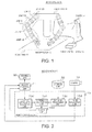
- Fig. 1 shows an example of an external appearance of a robot system in an embodiment of the invention.
- Fig. 2 is a block diagram showing an example of a functional configuration of the robot system.
- Fig. 3 shows an example of a shape model stored in a storage unit.
- Fig. 4 shows an example of a camera image created by a camera.
- Fig. 5 shows examples of two-dimensional images created from the shape model.
- Fig. 6 is a conceptual view for describing matching processing.
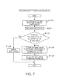
- Fig. 7 is a flowchart showing an example of operation of a robot control device.
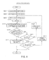
- Fig. 8 is a flowchart showing an example of the matching processing (Step S200).
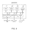
- Fig. 9 shows an example of a computer that realizes functions of the robot control device.
- Fig. 1 shows an example of an external appearance of a robot system 10 in the embodiment of the invention.
- the robot system 10 includes a robot body 11, a camera 14, and a robot control device 15.
- two arms 12 are attached to the robot body 11.
- An end effector 13 such as a hand is attached to the tip end of each of the arms 12.
- Each of the arms 12 has a plurality of joints 120 and a plurality of links 121.
- Each of the joints 120 rotatably (but rotatably within a given movable range) couples the robot body 11 with the link 121, the links 121 together, or the link 121 with the end effector 13.
- Each of the joints 120 is, for example, a rotary joint, which is disposed so as to be able to change an angle between the links 121 or to axially rotate the link 121.
- the robot body 11 can drive the joints 120 in conjunction with each other to thereby freely (but within a given movable range) move the end effector 13 and direct the end effector 13 in a desired direction.
- each of the arms 12 is a six-axis arm with six joints 120.
- the robot body 11 sends to the robot control device 15, with regard to a predetermined one of the end effectors 13, information regarding the position and orientation of the end effector 13 in a robot coordinate system recognized by the robot body 11.
- the position and orientation of the end effector 13 can also be referred to as a posture in a relative positional relation between the end effector 13 and the other parts of the robot. It is safe to say that a change in the position and orientation of the end effector 13 is a change in the posture of the end effector 13.
- the robot body 11 controls the end effector 13 so as to have a predetermined shape (for example, an opened state), and sends information of the position and orientation of the end effector 13 at that time to the robot control device 15.
- a predetermined shape for example, an opened state
- the camera 14 captures an image of the end effector 13 to create a camera image and sends the created camera image to the robot control device 15.
- a user adjusts the orientation of the camera 14 so that the predetermined one of the end effectors 13 is shown in the camera image captured by the camera 14.
- the robot control device 15 acquires, in calibration, the information of the position and orientation of the end effector 13 from the robot body 11, and acquires a camera image at that time from the camera 14. Then, the robot control device 15 specifies the position and orientation of the end effector 13 in a camera coordinate system projected onto the camera image.
- the robot control device 15 reconciles the two coordinate systems and outputs, as a calibration parameter, information that indicates the correspondence to the robot body 11.
- the robot body 11 acquires the camera image captured by the camera 14 and recognizes a predetermined target point in the image. Then, the robot body 11 calculates the control amount of the arm 12 by which the position and orientation of the predetermined end effector 13 are achieved with respect to the recognized target point, using the calibration parameter received from the robot control device 15. Then, the robot body 11 controls the arm 12 in accordance with the calculated control amount to thereby execute given work.
- Fig. 2 is a block diagram showing an example of a functional configuration of the robot system 10.
- a movable unit 20 is a part of the robot, the part being changeable in position and orientation, and functionally represents the arm 12, the link 121, the end effector 13, or the like.
- a motion control unit 21 represents a function in the robot body 11.
- a storage unit 22 as shown in Fig. 3 for example, data of a three-dimensional shape model 30 of the movable unit 20 is stored.
- the shape model 30 of the end effector 13 is stored in the storage unit 22.
- the shape model 30 is, for example, three-dimensional CAD data. Since the CAD data of the end effector 13 is data that has been already created in designing the robot system 10, there is no need to re-create data for calibration. Therefore, the cost and effort for performing calibration can be reduced.
- the shape model 30 is data including information of a three-dimensional external appearance shape and the dimensions thereof.
- CAD data including information of an internal shape and the like does not necessarily have to be used.
- the storage unit 22 is disposed outside the robot control device 15 and connected to the robot control device 15 via a communication cable.
- the robot control device 15 has a control information acquisition unit 150, a coordinate system calibration unit 151, a matching processing unit 152, an image acquisition unit 153, and an output unit 154.
- the control information acquisition unit 150 acquires, from the motion control unit 21, information of the position and orientation of the end effector 13 in the robot coordinate system recognized by the motion control unit 21, and sends the information to the coordinate system calibration unit 151.
- the image acquisition unit 153 acquires a camera image from the camera 14 and sends the image to the matching processing unit 152.
- a camera image 40 received from the camera 14 the end effector 13 is shown as shown in Fig. 4 for example.
- the matching processing unit 152 When the matching processing unit 152 receives the camera image from the image acquisition unit 153, the matching processing unit 152 acquires, from the storage unit 22, the data of the shape model 30 of the end effector 13 and the camera parameter.
- the matching processing unit 152 creates, as shown in Fig. 5 for example, two-dimensional images 31 of the three-dimensional shape model 30 as viewed from various directions.
- the two-dimensional images 31 shown in Fig. 5 are illustrative only. Actually, a two-dimensional image of the shape model 30 as viewed from a different direction than those may be created.
- the matching processing unit 152 scans, over the camera image 40, each of the created two-dimensional images 31 while changing the orientation or size thereof on the camera image 40 as shown in Fig. 6 for example, to search for the orientation and size of the two-dimensional image 31 whose degree of similarity to the camera image 40 is a given value or more.
- the matching processing unit 152 excludes a portion not seen from the camera 14, such as the connecting portion, in the two-dimensional image 31 from a calculation object of the degree of similarity.
- the matching processing unit 152 calculates, based on the size and orientation of the two-dimensional image 31 on the camera image 40, the position and orientation of the end effector 13 in the camera coordinate system, and sends information of the calculated position and orientation to the coordinate system calibration unit 151.
- the distance from the camera 14 to the end effector 13 is proportional to the size of the end effector 13 on the camera image 40 and the focal length of the camera 14.
- the matching processing unit 152 previously has the dimensions of the three-dimensional shape model 30 of the end effector 13 and the focal length of the camera 14, and therefore can calculate the distance from the camera 14 to the end effector 13 in the camera coordinate system.
- the shape model stored in the storage unit 22 is the three-dimensional CAD data of the end effector 13. Therefore, with the use of the CAD data, the matching processing unit 152 can calculate with high accuracy the distance from the camera 14 to the end effector 13 in the camera coordinate system.
- the coordinate system calibration unit 151 reconciles the camera coordinate system and the robot coordinate system based on the information of the position and orientation of the end effector 13 in the robot coordinate system received from the control information acquisition unit 150 and the information of the position and orientation of the end effector 13 in the camera coordinate system received from the matching processing unit 152. Then, the coordinate system calibration unit 151 sends a calibration parameter including information that indicates the correspondence to the output unit 154.
- the coordinate system calibration unit 151 obtains a rotation matrix and a translation vector between the camera coordinate system and the robot coordinate system using coordinates of a given number of points corresponding to those on the end effector 13 in each of the camera coordinate system and the robot coordinate system, to thereby reconcile the camera coordinate system and the robot coordinate system. Then, the coordinate system calibration unit 151 sends a calibration parameter including information of the obtained rotation matrix and translation vector to the output unit 154.
- the output unit 154 outputs the calibration parameter received from the coordinate system calibration unit 151 to the motion control unit 21.
- Fig. 7 shows a flowchart showing an example of operation of the robot control device 15.
- the robot control device 15 accepts an instruction of calibration from a user, whereby the robot system 10 starts the operation shown in the flowchart.
- the image acquisition unit 153 instructs the camera 14 to capture an image of the end effector 13.
- the camera 14 captures an image of the end effector 13 to create a camera image, and sends the created camera image to the robot control device 15 (Step S100).
- the image acquisition unit 153 receives the camera image from the camera 14 and sends the image to the matching processing unit 152.
- Fig. 8 is a flowchart showing an example of the matching processing (Step S200).
- the matching processing unit 152 acquires, from the storage unit 22, data of the shape model of the end effector 13 and a camera parameter (Step S201). Then, the matching processing unit 152 sets, as an initial value, the orientation of the shape model of the end effector 13 as viewed from the camera 14 (Step S202).
- the matching processing unit 152 creates a two-dimensional image of the end effector 13 viewed from the camera 14 in the set orientation (Step S203). Then, the matching processing unit 152 sets, as an initial value, the size of the created two-dimensional image on the camera image received from the image acquisition unit 153 (Step S204).
- the matching processing unit 152 scans, over the camera image, the two-dimensional image of the set size while changing the position or orientation thereof on the camera image, and calculates the degree of similarity between the two-dimensional image of the end effector 13 and the camera image (Step S205). Then, the matching processing unit 152 determines whether or not the position and orientation having a degree of similarity of a given value or more are present (Step S206).
- the matching processing unit 152 calculates the degree of similarity first by roughly changing the position and orientation every several pixels with regard to the position and every several degrees with regard to the orientation. It is preferable that if the position and orientation having a degree of similarity of a given value or more are not present, the matching processing unit 152 calculates, for the combination of position and orientation having the highest degree of similarity, the degree of similarity by finely changing the position and orientation pixel by pixel and degree by degree.
- the matching processing unit 152 specifies, based on the two-dimensional image and the size thereof at that time and the position and orientation thereof at that time, the position and orientation of the end effector 13 in the camera coordinate system (Step S211). Then, the matching processing unit 152 sends information of the specified position and orientation to the coordinate system calibration unit 151, and ends the matching processing (Step S200) shown in the flowchart.
- Step S206 determines whether or not all of size patterns are determined. If all of the size patterns are not determined (Step S207: No), the matching processing unit 152 changes the size of the two-dimensional image (Step S208), and again executes the processing shown in Step S205.
- the matching processing unit 152 executes Step S205 and Step S206 first by roughly changing the size for some different size patterns having a large difference in size. Then, it is preferable that if the combination of position and orientation having a degree of similarity of a given value or more cannot be detected, the matching processing unit 152 executes Step S205 and Step S206 by finely changing the size for some different size patterns having a small difference in size in the vicinity of the size where the highest degree of similarity is detected.
- Step S207 If all of the size patterns are determined (Step S207: Yes), the matching processing unit 152 determines whether or not all of orientation patterns are determined (Step S209). If all of the orientation patterns are not determined (Step S209: No), the matching processing unit 152 changes the orientation of the shape model of the end effector 13 as viewed from the camera 14 (Step S210), and again executes the processing shown in Step S203.
- the matching processing unit 152 executes Step S205 to Step S208 first by roughly changing the angle for some different angle patterns having a large difference in angle. Then, it is preferable that if the combination of position and orientation having a degree of similarity of a given value or more cannot be detected, the matching processing unit 152 executes Step S203 to Step S208 by finely changing the angle of the shape model for some different angle patterns having a small difference in angle in the vicinity of the angle where the highest degree of similarity is detected.
- Step S209 If all of the orientation patters are determined (Step S209: Yes), the matching processing unit 152 notifies the coordinate system calibration unit 151 that the position and orientation of the end effector 13 cannot be specified, and ends the matching processing (Step S200) shown in the flowchart.
- the coordinate system calibration unit 151 determines whether or not the position and orientation of the end effector 13 in the camera coordinate system can be specified in Step S200 (Step S101). If the position and orientation of the end effector 13 cannot be specified (Step S101: No), the coordinate system calibration unit 151 notifies an error of the user via a display device or the like, and the robot control device 15 ends the operation shown in the flowchart.
- Step S101 if the position and orientation of the end effector 13 can be specified (Step S101: Yes), the control information acquisition unit 150 acquires, from the motion control unit 21, information of the position and orientation of the end effector 13 in the robot coordinate system recognized by the motion control unit 21, and sends the information to the coordinate system calibration unit 151 (Step S102).
- the coordinate system calibration unit 151 reconciles the camera coordinate system and the robot coordinate system based on the information of the position and orientation of the end effector 13 in the robot coordinate system received from the control information acquisition unit 150 and the information of the position and orientation of the end effector 13 in the camera coordinate system received from the matching processing unit 152.
- the coordinate system calibration unit 151 sends to the output unit 154 a calibration parameter including information that indicates the correspondence.
- the output unit 154 outputs the calibration parameter received from the coordinate system calibration unit 151 to the motion control unit 21 (Step S103), and the robot control device 15 ends the operation shown in the flowchart.
- Fig. 9 shows an example of a hardware configuration of a computer 50 that realizes the functions of the robot control device 15.
- the computer 50 includes a CPU (Central Processing Unit) 51, a RAM (Random Access Memory) 52, a ROM (Read Only Memory) 53, an HDD (Hard Disk Drive) 54, a communication interface (I/F) 55, an input/output interface (I/F) 56, and a media interface (I/F) 57.
- a CPU Central Processing Unit
- RAM Random Access Memory
- ROM Read Only Memory
- HDD Hard Disk Drive
- I/F input/output interface
- I/F media interface
- the CPU 51 operates based on programs stored in the ROM 53 or the HDD 54 and controls the portions.
- the ROM 53 stores a boot program executed by the CPU 51 at the startup of the computer 50, a program dependent on hardware of the computer 50, and the like.
- the HDD 54 stores programs executed by the CPU 51 and data or the like used by the programs.
- the communication interface 55 receives data from another device via a communication line, sends the data to the CPU 51, and transmits data created by the CPU 51 to the device via the communication line.
- the CPU 51 acquires data from an input/output device such as a keyboard or a mouse via the input/output interface 56. Moreover, the CPU 51 outputs created data to an input/output device such as a display device or a printing device via the input/output interface 56.
- the media interface 57 reads programs or data stored in a storage medium 58 and provides the programs or data to the CPU 51 via the RAM 52.
- the CPU 51 loads the programs or data from the storage medium 58 onto the RAM 52 via the media interface 57, and executes the loaded programs.
- the storage medium 58 is, for example, an optical recording medium such as a DVD (Digital Versatile Disc) or a PD (Phase change rewritable Disk), a magneto-optical recording medium such as an MO (Magneto-Optical disk), a tape medium, a magnetic recording medium, a semiconductor memory, or the like.
- the CPU 51 of the computer 50 executes the programs loaded onto the RAM 52 to thereby realize the functions of the control information acquisition unit 150, the coordinate system calibration unit 151, the matching processing unit 152, the image acquisition unit 153, and the output unit 154.
- the CPU 51 of the computer 50 reads these programs from the storage medium 58 and executes them.
- the CPU 51 may acquire these programs from another device via a communication line.
- the invention is not limited to the embodiment described above and includes various modified examples.
- the robot control device 15 performs calibration based on the position and orientation of the end effector 13.
- the robot control device 15 may perform calibration based on the position and orientation of the link or joint in the arm, the entire arm, or the like as long as it is a portion that is movable in the robot.
- the shape model of the link or joint, the entire arm, or the like is stored in the storage unit 22.
- the movable unit to be an object of calibration is preferably a part having a large displacement.
- the shape of the entire arm is changed by a rotation angle at the joint, and therefore, for performing calibration, it is preferable to perform calibration after making the shape of the entire arm into a predetermined shape by, for example, setting the angles of all of the joints to a predetermined angle (for example, 0 degree).
- a predetermined angle for example, 0 degree.
- the matching processing unit 152 scans, over the enter camera image captured by the camera 14, the two-dimensional image created from the shape model of the end effector 13 in the storage unit 22 to calculate the degree of similarity.
- the invention is not limited thereto.
- identification information such as a mark may be provided on a surface of an real end effector 13, and the matching processing unit 152 may detect through image recognition the identification information in the camera image captured by the camera 14 and scan preferentially the vicinity of the detected identification information in the camera image to calculate the degree of similarity.
- the position and orientation of the movable unit in the camera coordinate system can be specified more rapidly.
- Identification information may also be provided on a surface of the shape model of the movable unit. In that case, based on an appearance of the identification information on the camera image, a direction in which the identification information provides such an appearance is specified, and a two-dimensional image viewed from the specified direction is created from the shape model, whereby the position and orientation of the movable unit in the camera coordinate system can be specified more rapidly.
- calibration is performed based on the position and orientation only of the end effector as the movable unit.
- the invention is not limited thereto.
- Some shape models of a plurality of different movable units (20) for example, different links, different joints, or the like, in addition to the end effector
- calibration may be performed using, among them, the shape model whose position and orientation can be specified in a camera image.
- identification information may be reconciled with the respective shape models
- identification information may also be provided on surfaces of the corresponding real movable units (20), and the matching processing unit 152 may detect through image recognition the identification information in the camera image captured by the camera 14 and specify the position and orientation of the movable unit on the camera image using the shape model corresponding to the detected identification information.
- a device having the functions of the movable unit 20, the motion control unit 21, and the robot control device 15, or a device further having the storage unit 22 may be configured as a robot.
- the motion control unit 21 may be included in the robot control device.
Landscapes
- Engineering & Computer Science (AREA)
- Robotics (AREA)
- Mechanical Engineering (AREA)
- Human Computer Interaction (AREA)
- Manipulator (AREA)
- Numerical Control (AREA)
Applications Claiming Priority (1)
| Application Number | Priority Date | Filing Date | Title |
|---|---|---|---|
| JP2012155252A JP5949242B2 (ja) | 2012-07-11 | 2012-07-11 | ロボットシステム、ロボット、ロボット制御装置、ロボット制御方法、およびロボット制御プログラム |
Publications (2)
| Publication Number | Publication Date |
|---|---|
| EP2684651A2 true EP2684651A2 (de) | 2014-01-15 |
| EP2684651A3 EP2684651A3 (de) | 2015-05-06 |
Family
ID=48790214
Family Applications (1)
| Application Number | Title | Priority Date | Filing Date |
|---|---|---|---|
| EP20130175706 Withdrawn EP2684651A3 (de) | 2012-07-11 | 2013-07-09 | Robotersystem, Roboter, Robotersteuervorrichtung, Robotersteuerverfahren und Robotersteuerprogramm |
Country Status (6)
| Country | Link |
|---|---|
| US (1) | US20140018957A1 (de) |
| EP (1) | EP2684651A3 (de) |
| JP (1) | JP5949242B2 (de) |
| KR (1) | KR20140008262A (de) |
| CN (1) | CN103538061A (de) |
| TW (1) | TW201403277A (de) |
Cited By (10)
| Publication number | Priority date | Publication date | Assignee | Title |
|---|---|---|---|---|
| CN104647377A (zh) * | 2014-12-30 | 2015-05-27 | 杭州新松机器人自动化有限公司 | 一种基于认知系统的工业机器人及其控制方法 |
| DE102015000589B4 (de) * | 2014-01-23 | 2016-07-14 | Fanuc Corporation | Datenerzeugungsvorrichtung für einen visuellen Sensor und ein Erfassungssimulationssystem |
| CN106003023A (zh) * | 2016-05-25 | 2016-10-12 | 珠海格力智能装备有限公司 | 机器人运动控制系统和方法 |
| US20180003488A1 (en) * | 2016-06-30 | 2018-01-04 | Rolls-Royce Plc | Methods, apparatus, computer programs and non-transitory computer readable storage mediums for controlling a robot within a volume |
| CN108568829A (zh) * | 2017-03-08 | 2018-09-25 | 发那科株式会社 | 机械系统 |
| WO2018197079A1 (de) * | 2017-04-27 | 2018-11-01 | Robert Bosch Gmbh | Steuereinrichtung für eine prüfvorrichtung, prüfanordnung mit der steuereinrichtung, verfahren zur ansteuerung der prüfanordnung und computerprogramm |
| WO2018197078A1 (de) * | 2017-04-27 | 2018-11-01 | Robert Bosch Gmbh | Prüfvorrichtung zur optischen prüfung eines objektes, produktionsanlage mit der prüfvorrichtung und verfahren zur optischen prüfung des objektes mit der prüfvorrichtung |
| CN110722548A (zh) * | 2018-07-17 | 2020-01-24 | 富士施乐株式会社 | 机器人控制系统、机器人装置以及存储介质 |
| CN111136654A (zh) * | 2019-12-03 | 2020-05-12 | 秒针信息技术有限公司 | 送餐机器人位置提示方法和系统及送餐机器人 |
| CN112077841A (zh) * | 2020-08-10 | 2020-12-15 | 北京大学 | 一种提升机器人手臂操纵精度的多关节联动方法及系统 |
Families Citing this family (33)
| Publication number | Priority date | Publication date | Assignee | Title |
|---|---|---|---|---|
| JP2015089575A (ja) * | 2013-11-05 | 2015-05-11 | セイコーエプソン株式会社 | ロボット、制御装置、ロボットシステム及び制御方法 |
| WO2015197100A1 (en) | 2014-06-23 | 2015-12-30 | Abb Technology Ltd | Method for calibrating a robot and a robot system |
| JP6372198B2 (ja) * | 2014-07-01 | 2018-08-15 | セイコーエプソン株式会社 | ロボットシステム及び処理装置 |
| JP6415190B2 (ja) | 2014-09-03 | 2018-10-31 | キヤノン株式会社 | ロボット装置、ロボット制御プログラム、記録媒体、およびロボット装置の制御方法 |
| CN104476549B (zh) * | 2014-11-20 | 2016-04-27 | 北京卫星环境工程研究所 | 基于视觉测量的机械臂运动路径补偿方法 |
| JP2016107379A (ja) * | 2014-12-08 | 2016-06-20 | ファナック株式会社 | 拡張現実対応ディスプレイを備えたロボットシステム |
| EP3277468A4 (de) | 2015-04-02 | 2019-10-16 | ABB Schweiz AG | Verfahren zur inbetriebnahme eines industrieroboters, industrierobotersystem und steuerungssystem damit |
| US9964941B2 (en) * | 2015-05-06 | 2018-05-08 | Aleader Vision Technology Co., Ltd. | Method, device and system for improving system accuracy of X-Y motion platform |
| DE102015209899B4 (de) * | 2015-05-29 | 2019-06-19 | Kuka Roboter Gmbh | Auswahl eines Gerätes oder eines Objektes mit Hilfe einer Kamera |
| JP6174654B2 (ja) * | 2015-10-15 | 2017-08-02 | ファナック株式会社 | センサの位置と向きを算出する機能を備えたロボットシステム |
| US10363667B2 (en) * | 2015-11-30 | 2019-07-30 | Autodesk, Inc. | Optical measurement of object location in three dimensions |
| EP3411194A1 (de) * | 2016-02-02 | 2018-12-12 | ABB Schweiz AG | Kalibrierung eines robotersystems |
| US10105847B1 (en) * | 2016-06-08 | 2018-10-23 | X Development Llc | Detecting and responding to geometric changes to robots |
| US10661442B2 (en) * | 2017-02-03 | 2020-05-26 | Abb Schweiz Ag | Calibration article for a 3D vision robotic system |
| JP6877191B2 (ja) * | 2017-03-03 | 2021-05-26 | 株式会社キーエンス | 画像処理装置、画像処理方法、画像処理プログラム及びコンピュータで読み取り可能な記録媒体 |
| WO2018199947A1 (en) * | 2017-04-26 | 2018-11-01 | Hewlett-Packard Development Company, L.P. | Robotic structure calibrations |
| CN110621447B (zh) * | 2017-05-22 | 2022-11-11 | Abb瑞士股份有限公司 | 机器人传送器校准方法、机器人系统以及控制系统 |
| US10853539B2 (en) * | 2017-05-26 | 2020-12-01 | Autodesk, Inc. | Robotic assembly of a mesh surface |
| JP6633584B2 (ja) * | 2017-10-02 | 2020-01-22 | ファナック株式会社 | ロボットシステム |
| US11504853B2 (en) * | 2017-11-16 | 2022-11-22 | General Electric Company | Robotic system architecture and control processes |
| DE102018101162B4 (de) * | 2018-01-19 | 2023-09-21 | Hochschule Reutlingen | Messsystem und Verfahren zur extrinsischen Kalibrierung |
| JP7017469B2 (ja) * | 2018-05-16 | 2022-02-08 | 株式会社安川電機 | 操作用デバイス、制御システム、制御方法及びプログラム |
| JP2020066066A (ja) * | 2018-10-22 | 2020-04-30 | セイコーエプソン株式会社 | ロボットシステム、ロボットの校正治具、ロボットの校正方法 |
| JP6829236B2 (ja) * | 2018-11-15 | 2021-02-10 | ファナック株式会社 | ロボット制御装置及びロボットシステム |
| TWI696529B (zh) * | 2018-11-30 | 2020-06-21 | 財團法人金屬工業研究發展中心 | 自動定位方法以及自動控制裝置 |
| CN111890371B (zh) * | 2019-03-29 | 2021-05-04 | 牧今科技 | 验证和更新机器人控制用校准信息的方法和控制系统 |
| US10906184B2 (en) | 2019-03-29 | 2021-02-02 | Mujin, Inc. | Method and control system for verifying and updating camera calibration for robot control |
| CN112677146A (zh) * | 2019-10-18 | 2021-04-20 | 牧今科技 | 验证和更新机器人控制用校准信息的方法和控制系统 |
| US10399227B1 (en) | 2019-03-29 | 2019-09-03 | Mujin, Inc. | Method and control system for verifying and updating camera calibration for robot control |
| JP7326911B2 (ja) * | 2019-06-20 | 2023-08-16 | オムロン株式会社 | 制御システムおよび制御方法 |
| JP7264763B2 (ja) * | 2019-08-07 | 2023-04-25 | 株式会社日立製作所 | キャリブレーション装置 |
| US11182178B1 (en) | 2020-02-21 | 2021-11-23 | Automation Anywhere, Inc. | Detection of user interface controls via invariance guided sub-control learning |
| WO2021199305A1 (ja) * | 2020-03-31 | 2021-10-07 | 日本電気株式会社 | 制御装置、制御システム、制御方法、および、制御プログラムが記録された記録媒体 |
Citations (1)
| Publication number | Priority date | Publication date | Assignee | Title |
|---|---|---|---|---|
| JPH10340112A (ja) | 1997-06-06 | 1998-12-22 | Matsushita Electric Ind Co Ltd | 自動キャリブレーション機能付きロボット |
Family Cites Families (13)
| Publication number | Priority date | Publication date | Assignee | Title |
|---|---|---|---|---|
| JPS63104105A (ja) * | 1986-10-22 | 1988-05-09 | Aisin Seiki Co Ltd | ロボツト視覚座標系の換算方法 |
| JPH06134691A (ja) * | 1992-10-23 | 1994-05-17 | Hitachi Ltd | 位置検出方法およびこれを用いたフレキシブル生産システム |
| JP3402021B2 (ja) * | 1995-11-07 | 2003-04-28 | 株式会社明電舎 | ロボット装置の相対位置姿勢検出方法 |
| JP3415427B2 (ja) * | 1998-02-25 | 2003-06-09 | 富士通株式会社 | ロボットシミュレーションにおけるキャリブレーション装置 |
| JP3985677B2 (ja) * | 2002-12-25 | 2007-10-03 | 株式会社安川電機 | 水平多関節ロボットの干渉チェック装置および方法 |
| JP2004318823A (ja) * | 2003-03-28 | 2004-11-11 | Seiko Epson Corp | 情報表示システム、情報処理装置、ポインティング装置および情報表示システムにおけるポインタマーク表示方法 |
| JP3946711B2 (ja) * | 2004-06-02 | 2007-07-18 | ファナック株式会社 | ロボットシステム |
| US8073528B2 (en) * | 2007-09-30 | 2011-12-06 | Intuitive Surgical Operations, Inc. | Tool tracking systems, methods and computer products for image guided surgery |
| DE102006049956A1 (de) * | 2006-10-19 | 2008-04-24 | Abb Ag | System und Verfahren zur automatisierten Ver- und/oder Bearbeitung von Werkstücken |
| US9393694B2 (en) * | 2010-05-14 | 2016-07-19 | Cognex Corporation | System and method for robust calibration between a machine vision system and a robot |
| CN102294695A (zh) * | 2010-06-25 | 2011-12-28 | 鸿富锦精密工业(深圳)有限公司 | 机器人标定方法及标定系统 |
| JP5449112B2 (ja) * | 2010-11-18 | 2014-03-19 | 株式会社神戸製鋼所 | 溶接状況監視方法及び溶接状況監視装置 |
| US9188973B2 (en) * | 2011-07-08 | 2015-11-17 | Restoration Robotics, Inc. | Calibration and transformation of a camera system's coordinate system |
-
2012
- 2012-07-11 JP JP2012155252A patent/JP5949242B2/ja not_active Expired - Fee Related
-
2013
- 2013-07-08 TW TW102124403A patent/TW201403277A/zh unknown
- 2013-07-09 EP EP20130175706 patent/EP2684651A3/de not_active Withdrawn
- 2013-07-10 KR KR1020130080910A patent/KR20140008262A/ko not_active Application Discontinuation
- 2013-07-10 CN CN201310289275.7A patent/CN103538061A/zh active Pending
- 2013-07-10 US US13/938,587 patent/US20140018957A1/en not_active Abandoned
Patent Citations (1)
| Publication number | Priority date | Publication date | Assignee | Title |
|---|---|---|---|---|
| JPH10340112A (ja) | 1997-06-06 | 1998-12-22 | Matsushita Electric Ind Co Ltd | 自動キャリブレーション機能付きロボット |
Cited By (18)
| Publication number | Priority date | Publication date | Assignee | Title |
|---|---|---|---|---|
| DE102015000589B4 (de) * | 2014-01-23 | 2016-07-14 | Fanuc Corporation | Datenerzeugungsvorrichtung für einen visuellen Sensor und ein Erfassungssimulationssystem |
| US9519736B2 (en) | 2014-01-23 | 2016-12-13 | Fanuc Corporation | Data generation device for vision sensor and detection simulation system |
| CN104647377A (zh) * | 2014-12-30 | 2015-05-27 | 杭州新松机器人自动化有限公司 | 一种基于认知系统的工业机器人及其控制方法 |
| CN104647377B (zh) * | 2014-12-30 | 2016-08-24 | 杭州新松机器人自动化有限公司 | 一种基于认知系统的工业机器人及其控制方法 |
| CN106003023A (zh) * | 2016-05-25 | 2016-10-12 | 珠海格力智能装备有限公司 | 机器人运动控制系统和方法 |
| US10563979B2 (en) * | 2016-06-30 | 2020-02-18 | Rolls-Royce Plc | Methods, apparatus, computer programs and non-transitory computer readable storage mediums for controlling a robot within a volume |
| EP3266572A3 (de) * | 2016-06-30 | 2018-01-24 | Rolls-Royce plc | Verfahren, vorrichtung, computerprogramme und nichttransitorische computerlesbare speichermedien zur steuerung eines roboters in einem volumen |
| US20180003488A1 (en) * | 2016-06-30 | 2018-01-04 | Rolls-Royce Plc | Methods, apparatus, computer programs and non-transitory computer readable storage mediums for controlling a robot within a volume |
| CN108568829A (zh) * | 2017-03-08 | 2018-09-25 | 发那科株式会社 | 机械系统 |
| CN108568829B (zh) * | 2017-03-08 | 2019-07-16 | 发那科株式会社 | 机械系统 |
| US10589429B2 (en) | 2017-03-08 | 2020-03-17 | Fanuc Corporation | Machine system |
| WO2018197079A1 (de) * | 2017-04-27 | 2018-11-01 | Robert Bosch Gmbh | Steuereinrichtung für eine prüfvorrichtung, prüfanordnung mit der steuereinrichtung, verfahren zur ansteuerung der prüfanordnung und computerprogramm |
| WO2018197078A1 (de) * | 2017-04-27 | 2018-11-01 | Robert Bosch Gmbh | Prüfvorrichtung zur optischen prüfung eines objektes, produktionsanlage mit der prüfvorrichtung und verfahren zur optischen prüfung des objektes mit der prüfvorrichtung |
| US11090812B2 (en) | 2017-04-27 | 2021-08-17 | Robert Bosch Gmbh | Inspection apparatus for optically inspecting an object, production facility equipped with the inspection apparatus, and method for optically inspecting the object using the inspection apparatus |
| EP3615908B1 (de) * | 2017-04-27 | 2023-08-30 | Robert Bosch GmbH | Steuereinrichtung für eine prüfvorrichtung, prüfanordnung mit der steuereinrichtung, verfahren zur ansteuerung der prüfanordnung und computerprogramm |
| CN110722548A (zh) * | 2018-07-17 | 2020-01-24 | 富士施乐株式会社 | 机器人控制系统、机器人装置以及存储介质 |
| CN111136654A (zh) * | 2019-12-03 | 2020-05-12 | 秒针信息技术有限公司 | 送餐机器人位置提示方法和系统及送餐机器人 |
| CN112077841A (zh) * | 2020-08-10 | 2020-12-15 | 北京大学 | 一种提升机器人手臂操纵精度的多关节联动方法及系统 |
Also Published As
| Publication number | Publication date |
|---|---|
| EP2684651A3 (de) | 2015-05-06 |
| TW201403277A (zh) | 2014-01-16 |
| KR20140008262A (ko) | 2014-01-21 |
| US20140018957A1 (en) | 2014-01-16 |
| JP2014014912A (ja) | 2014-01-30 |
| CN103538061A (zh) | 2014-01-29 |
| JP5949242B2 (ja) | 2016-07-06 |
Similar Documents
| Publication | Publication Date | Title |
|---|---|---|
| EP2684651A2 (de) | Robotersystem, Roboter, Robotersteuervorrichtung, Robotersteuerverfahren und Robotersteuerprogramm | |
| JP6527178B2 (ja) | 視覚センサのキャリブレーション装置、方法及びプログラム | |
| CN109153125B (zh) | 用于定向工业机器人的方法和工业机器人 | |
| JP6573354B2 (ja) | 画像処理装置、画像処理方法、及びプログラム | |
| US20200284573A1 (en) | Position and orientation measuring apparatus, information processing apparatus and information processing method | |
| JP6711591B2 (ja) | ロボット制御装置およびロボット制御方法 | |
| EP3753685B1 (de) | Steuerungssystem und steuerungsverfahren | |
| JP6271953B2 (ja) | 画像処理装置、画像処理方法 | |
| US9135519B2 (en) | Pattern matching method and pattern matching apparatus | |
| JP2018111166A (ja) | 視覚センサのキャリブレーション装置、方法及びプログラム | |
| KR101964332B1 (ko) | 핸드-아이 캘리브레이션 방법, 이를 실행하기 위한 컴퓨터 프로그램 및 로봇 시스템 | |
| US20180338090A1 (en) | Image processing system, image processing device, and image processing program | |
| JP6973444B2 (ja) | 制御システム、情報処理装置および制御方法 | |
| JP6075888B2 (ja) | 画像処理方法、ロボットの制御方法 | |
| JP2020047049A (ja) | 画像処理装置及び画像処理方法 | |
| JP6922348B2 (ja) | 情報処理装置、方法、及びプログラム | |
| JP4694624B2 (ja) | 画像補正装置及び方法、並びにコンピュータプログラム | |
| JP7372076B2 (ja) | 画像処理システム | |
| JP6337530B2 (ja) | 画像処理装置、画像処理方法、および画像処理プログラム | |
| CN115082550A (zh) | 从对象的相机图像中定位对象的位置的设备和方法 | |
| CN111742349B (zh) | 信息处理装置、信息处理方法以及信息处理存储介质 | |
| CN111971529A (zh) | 用于管理机器人系统的方法和装置 | |
| JP2012236266A (ja) | ロボット制御システム、ロボットシステム及びプログラム | |
| WO2022172471A1 (ja) | 支援システム、画像処理装置、支援方法およびプログラム | |
| JP2023011319A (ja) | 調整支援システムおよび調整支援方法 |
Legal Events
| Date | Code | Title | Description |
|---|---|---|---|
| PUAI | Public reference made under article 153(3) epc to a published international application that has entered the european phase |
Free format text: ORIGINAL CODE: 0009012 |
|
| AK | Designated contracting states |
Kind code of ref document: A2 Designated state(s): AL AT BE BG CH CY CZ DE DK EE ES FI FR GB GR HR HU IE IS IT LI LT LU LV MC MK MT NL NO PL PT RO RS SE SI SK SM TR |
|
| AX | Request for extension of the european patent |
Extension state: BA ME |
|
| PUAL | Search report despatched |
Free format text: ORIGINAL CODE: 0009013 |
|
| AK | Designated contracting states |
Kind code of ref document: A3 Designated state(s): AL AT BE BG CH CY CZ DE DK EE ES FI FR GB GR HR HU IE IS IT LI LT LU LV MC MK MT NL NO PL PT RO RS SE SI SK SM TR |
|
| AX | Request for extension of the european patent |
Extension state: BA ME |
|
| RIC1 | Information provided on ipc code assigned before grant |
Ipc: B25J 9/16 20060101AFI20150330BHEP |
|
| 17P | Request for examination filed |
Effective date: 20151012 |
|
| RBV | Designated contracting states (corrected) |
Designated state(s): AL AT BE BG CH CY CZ DE DK EE ES FI FR GB GR HR HU IE IS IT LI LT LU LV MC MK MT NL NO PL PT RO RS SE SI SK SM TR |
|
| STAA | Information on the status of an ep patent application or granted ep patent |
Free format text: STATUS: THE APPLICATION HAS BEEN WITHDRAWN |
|
| 18W | Application withdrawn |
Effective date: 20190304 |