EP2684241B1 - Elektrischer energiespeicher mit integrierter flexibler kühl-heizkombination - Google Patents
Elektrischer energiespeicher mit integrierter flexibler kühl-heizkombination Download PDFInfo
- Publication number
- EP2684241B1 EP2684241B1 EP12708309.5A EP12708309A EP2684241B1 EP 2684241 B1 EP2684241 B1 EP 2684241B1 EP 12708309 A EP12708309 A EP 12708309A EP 2684241 B1 EP2684241 B1 EP 2684241B1
- Authority
- EP
- European Patent Office
- Prior art keywords
- energy storage
- storage device
- cooling
- heating element
- individual
- Prior art date
- Legal status (The legal status is an assumption and is not a legal conclusion. Google has not performed a legal analysis and makes no representation as to the accuracy of the status listed.)
- Not-in-force
Links
Images


Classifications
-
- H—ELECTRICITY
- H01—ELECTRIC ELEMENTS
- H01M—PROCESSES OR MEANS, e.g. BATTERIES, FOR THE DIRECT CONVERSION OF CHEMICAL ENERGY INTO ELECTRICAL ENERGY
- H01M8/00—Fuel cells; Manufacture thereof
- H01M8/02—Details
-
- H—ELECTRICITY
- H01—ELECTRIC ELEMENTS
- H01M—PROCESSES OR MEANS, e.g. BATTERIES, FOR THE DIRECT CONVERSION OF CHEMICAL ENERGY INTO ELECTRICAL ENERGY
- H01M8/00—Fuel cells; Manufacture thereof
- H01M8/04—Auxiliary arrangements, e.g. for control of pressure or for circulation of fluids
- H01M8/04007—Auxiliary arrangements, e.g. for control of pressure or for circulation of fluids related to heat exchange
- H01M8/04037—Electrical heating
-
- H—ELECTRICITY
- H01—ELECTRIC ELEMENTS
- H01M—PROCESSES OR MEANS, e.g. BATTERIES, FOR THE DIRECT CONVERSION OF CHEMICAL ENERGY INTO ELECTRICAL ENERGY
- H01M10/00—Secondary cells; Manufacture thereof
- H01M10/60—Heating or cooling; Temperature control
- H01M10/62—Heating or cooling; Temperature control specially adapted for specific applications
- H01M10/625—Vehicles
-
- B—PERFORMING OPERATIONS; TRANSPORTING
- B60—VEHICLES IN GENERAL
- B60L—PROPULSION OF ELECTRICALLY-PROPELLED VEHICLES; SUPPLYING ELECTRIC POWER FOR AUXILIARY EQUIPMENT OF ELECTRICALLY-PROPELLED VEHICLES; ELECTRODYNAMIC BRAKE SYSTEMS FOR VEHICLES IN GENERAL; MAGNETIC SUSPENSION OR LEVITATION FOR VEHICLES; MONITORING OPERATING VARIABLES OF ELECTRICALLY-PROPELLED VEHICLES; ELECTRIC SAFETY DEVICES FOR ELECTRICALLY-PROPELLED VEHICLES
- B60L1/00—Supplying electric power to auxiliary equipment of vehicles
- B60L1/02—Supplying electric power to auxiliary equipment of vehicles to electric heating circuits
- B60L1/04—Supplying electric power to auxiliary equipment of vehicles to electric heating circuits fed by the power supply line
- B60L1/06—Supplying electric power to auxiliary equipment of vehicles to electric heating circuits fed by the power supply line using only one supply
- B60L1/08—Methods and devices for control or regulation
-
- B—PERFORMING OPERATIONS; TRANSPORTING
- B60—VEHICLES IN GENERAL
- B60L—PROPULSION OF ELECTRICALLY-PROPELLED VEHICLES; SUPPLYING ELECTRIC POWER FOR AUXILIARY EQUIPMENT OF ELECTRICALLY-PROPELLED VEHICLES; ELECTRODYNAMIC BRAKE SYSTEMS FOR VEHICLES IN GENERAL; MAGNETIC SUSPENSION OR LEVITATION FOR VEHICLES; MONITORING OPERATING VARIABLES OF ELECTRICALLY-PROPELLED VEHICLES; ELECTRIC SAFETY DEVICES FOR ELECTRICALLY-PROPELLED VEHICLES
- B60L50/00—Electric propulsion with power supplied within the vehicle
- B60L50/50—Electric propulsion with power supplied within the vehicle using propulsion power supplied by batteries or fuel cells
- B60L50/60—Electric propulsion with power supplied within the vehicle using propulsion power supplied by batteries or fuel cells using power supplied by batteries
- B60L50/64—Constructional details of batteries specially adapted for electric vehicles
-
- B—PERFORMING OPERATIONS; TRANSPORTING
- B60—VEHICLES IN GENERAL
- B60L—PROPULSION OF ELECTRICALLY-PROPELLED VEHICLES; SUPPLYING ELECTRIC POWER FOR AUXILIARY EQUIPMENT OF ELECTRICALLY-PROPELLED VEHICLES; ELECTRODYNAMIC BRAKE SYSTEMS FOR VEHICLES IN GENERAL; MAGNETIC SUSPENSION OR LEVITATION FOR VEHICLES; MONITORING OPERATING VARIABLES OF ELECTRICALLY-PROPELLED VEHICLES; ELECTRIC SAFETY DEVICES FOR ELECTRICALLY-PROPELLED VEHICLES
- B60L58/00—Methods or circuit arrangements for monitoring or controlling batteries or fuel cells, specially adapted for electric vehicles
- B60L58/10—Methods or circuit arrangements for monitoring or controlling batteries or fuel cells, specially adapted for electric vehicles for monitoring or controlling batteries
- B60L58/24—Methods or circuit arrangements for monitoring or controlling batteries or fuel cells, specially adapted for electric vehicles for monitoring or controlling batteries for controlling the temperature of batteries
- B60L58/27—Methods or circuit arrangements for monitoring or controlling batteries or fuel cells, specially adapted for electric vehicles for monitoring or controlling batteries for controlling the temperature of batteries by heating
-
- H—ELECTRICITY
- H01—ELECTRIC ELEMENTS
- H01M—PROCESSES OR MEANS, e.g. BATTERIES, FOR THE DIRECT CONVERSION OF CHEMICAL ENERGY INTO ELECTRICAL ENERGY
- H01M10/00—Secondary cells; Manufacture thereof
- H01M10/60—Heating or cooling; Temperature control
- H01M10/64—Heating or cooling; Temperature control characterised by the shape of the cells
- H01M10/647—Prismatic or flat cells, e.g. pouch cells
-
- H—ELECTRICITY
- H01—ELECTRIC ELEMENTS
- H01M—PROCESSES OR MEANS, e.g. BATTERIES, FOR THE DIRECT CONVERSION OF CHEMICAL ENERGY INTO ELECTRICAL ENERGY
- H01M10/00—Secondary cells; Manufacture thereof
- H01M10/60—Heating or cooling; Temperature control
- H01M10/65—Means for temperature control structurally associated with the cells
- H01M10/655—Solid structures for heat exchange or heat conduction
-
- H—ELECTRICITY
- H01—ELECTRIC ELEMENTS
- H01M—PROCESSES OR MEANS, e.g. BATTERIES, FOR THE DIRECT CONVERSION OF CHEMICAL ENERGY INTO ELECTRICAL ENERGY
- H01M10/00—Secondary cells; Manufacture thereof
- H01M10/60—Heating or cooling; Temperature control
- H01M10/65—Means for temperature control structurally associated with the cells
- H01M10/657—Means for temperature control structurally associated with the cells by electric or electromagnetic means
-
- H—ELECTRICITY
- H01—ELECTRIC ELEMENTS
- H01M—PROCESSES OR MEANS, e.g. BATTERIES, FOR THE DIRECT CONVERSION OF CHEMICAL ENERGY INTO ELECTRICAL ENERGY
- H01M8/00—Fuel cells; Manufacture thereof
- H01M8/04—Auxiliary arrangements, e.g. for control of pressure or for circulation of fluids
-
- H—ELECTRICITY
- H01—ELECTRIC ELEMENTS
- H01M—PROCESSES OR MEANS, e.g. BATTERIES, FOR THE DIRECT CONVERSION OF CHEMICAL ENERGY INTO ELECTRICAL ENERGY
- H01M8/00—Fuel cells; Manufacture thereof
- H01M8/04—Auxiliary arrangements, e.g. for control of pressure or for circulation of fluids
- H01M8/04007—Auxiliary arrangements, e.g. for control of pressure or for circulation of fluids related to heat exchange
- H01M8/04067—Heat exchange or temperature measuring elements, thermal insulation, e.g. heat pipes, heat pumps, fins
- H01M8/04074—Heat exchange unit structures specially adapted for fuel cell
-
- H—ELECTRICITY
- H01—ELECTRIC ELEMENTS
- H01M—PROCESSES OR MEANS, e.g. BATTERIES, FOR THE DIRECT CONVERSION OF CHEMICAL ENERGY INTO ELECTRICAL ENERGY
- H01M8/00—Fuel cells; Manufacture thereof
- H01M8/04—Auxiliary arrangements, e.g. for control of pressure or for circulation of fluids
- H01M8/04223—Auxiliary arrangements, e.g. for control of pressure or for circulation of fluids during start-up or shut-down; Depolarisation or activation, e.g. purging; Means for short-circuiting defective fuel cells
- H01M8/04253—Means for solving freezing problems
-
- H—ELECTRICITY
- H01—ELECTRIC ELEMENTS
- H01M—PROCESSES OR MEANS, e.g. BATTERIES, FOR THE DIRECT CONVERSION OF CHEMICAL ENERGY INTO ELECTRICAL ENERGY
- H01M8/00—Fuel cells; Manufacture thereof
- H01M8/04—Auxiliary arrangements, e.g. for control of pressure or for circulation of fluids
- H01M8/04298—Processes for controlling fuel cells or fuel cell systems
- H01M8/04313—Processes for controlling fuel cells or fuel cell systems characterised by the detection or assessment of variables; characterised by the detection or assessment of failure or abnormal function
- H01M8/0432—Temperature; Ambient temperature
- H01M8/04365—Temperature; Ambient temperature of other components of a fuel cell or fuel cell stacks
-
- H—ELECTRICITY
- H05—ELECTRIC TECHNIQUES NOT OTHERWISE PROVIDED FOR
- H05B—ELECTRIC HEATING; ELECTRIC LIGHT SOURCES NOT OTHERWISE PROVIDED FOR; CIRCUIT ARRANGEMENTS FOR ELECTRIC LIGHT SOURCES, IN GENERAL
- H05B3/00—Ohmic-resistance heating
- H05B3/20—Heating elements having extended surface area substantially in a two-dimensional [2D] plane, e.g. plate-heater
- H05B3/34—Heating elements having extended surface area substantially in a two-dimensional [2D] plane, e.g. plate-heater flexible, e.g. heating nets or webs
-
- H—ELECTRICITY
- H01—ELECTRIC ELEMENTS
- H01M—PROCESSES OR MEANS, e.g. BATTERIES, FOR THE DIRECT CONVERSION OF CHEMICAL ENERGY INTO ELECTRICAL ENERGY
- H01M2220/00—Batteries for particular applications
- H01M2220/20—Batteries in motive systems, e.g. vehicle, ship, plane
-
- Y—GENERAL TAGGING OF NEW TECHNOLOGICAL DEVELOPMENTS; GENERAL TAGGING OF CROSS-SECTIONAL TECHNOLOGIES SPANNING OVER SEVERAL SECTIONS OF THE IPC; TECHNICAL SUBJECTS COVERED BY FORMER USPC CROSS-REFERENCE ART COLLECTIONS [XRACs] AND DIGESTS
- Y02—TECHNOLOGIES OR APPLICATIONS FOR MITIGATION OR ADAPTATION AGAINST CLIMATE CHANGE
- Y02E—REDUCTION OF GREENHOUSE GAS [GHG] EMISSIONS, RELATED TO ENERGY GENERATION, TRANSMISSION OR DISTRIBUTION
- Y02E60/00—Enabling technologies; Technologies with a potential or indirect contribution to GHG emissions mitigation
- Y02E60/10—Energy storage using batteries
-
- Y—GENERAL TAGGING OF NEW TECHNOLOGICAL DEVELOPMENTS; GENERAL TAGGING OF CROSS-SECTIONAL TECHNOLOGIES SPANNING OVER SEVERAL SECTIONS OF THE IPC; TECHNICAL SUBJECTS COVERED BY FORMER USPC CROSS-REFERENCE ART COLLECTIONS [XRACs] AND DIGESTS
- Y02—TECHNOLOGIES OR APPLICATIONS FOR MITIGATION OR ADAPTATION AGAINST CLIMATE CHANGE
- Y02E—REDUCTION OF GREENHOUSE GAS [GHG] EMISSIONS, RELATED TO ENERGY GENERATION, TRANSMISSION OR DISTRIBUTION
- Y02E60/00—Enabling technologies; Technologies with a potential or indirect contribution to GHG emissions mitigation
- Y02E60/30—Hydrogen technology
- Y02E60/50—Fuel cells
-
- Y—GENERAL TAGGING OF NEW TECHNOLOGICAL DEVELOPMENTS; GENERAL TAGGING OF CROSS-SECTIONAL TECHNOLOGIES SPANNING OVER SEVERAL SECTIONS OF THE IPC; TECHNICAL SUBJECTS COVERED BY FORMER USPC CROSS-REFERENCE ART COLLECTIONS [XRACs] AND DIGESTS
- Y02—TECHNOLOGIES OR APPLICATIONS FOR MITIGATION OR ADAPTATION AGAINST CLIMATE CHANGE
- Y02T—CLIMATE CHANGE MITIGATION TECHNOLOGIES RELATED TO TRANSPORTATION
- Y02T10/00—Road transport of goods or passengers
- Y02T10/60—Other road transportation technologies with climate change mitigation effect
- Y02T10/70—Energy storage systems for electromobility, e.g. batteries
Definitions
- the invention relates to an electrical energy store, in particular for motor vehicles, having at least one battery module with a plurality of arranged between two outer end plates in a stack of individual cells.
- the WO 2008/082399 A1 discloses a fuel cell having a plurality of single cells forming a stack.
- a heating element is arranged in the region of the outer individual cells - but not between two individual cells.
- a fuel cell stack having a resistance heater for heating the outer end cells is known.
- the DE 10 2007 055 252 A1 describes an intelligent membrane electrode assembly for a fuel cell wherein a flexible printed circuit is mounted on a surface of an ion exchange membrane carrier film.
- the flexible printed circuit has an electrical heating element.
- fuel cells are not electrical energy stores, but converters.
- fuel cells differ significantly from electrical energy storage devices and are only able to extract electrical energy from chemical reactions, but they can not be stored.
- the object of the invention is to avoid the disadvantages mentioned and to enable optimal conditioning of the battery module with little effort.
- this is achieved in that between at least two individual cells, a preferably flexible electrical heating element is arranged, wherein preferably the heating element is formed by a preferably flexible heating foil. Due to the flexible design, a contour adjustment is possible.
- the electrical heating element is arranged between two individual modules.
- the heating element may be a resistance heating element with heating wires.
- the heating element is at least partially surrounded by a cooling element and laser welded.
- the cooling element may be formed by a preferably made of sheet metal cooling plate. But it is also possible that the cooling plate is made of plastic.
- a particularly good cooling effect can be achieved if the cooling element is folded over a large area around the heating element and thus encloses both sides of the heating element. Equally, however, a one-sided contacting of the cooling element with the heating element is possible.
- the cooling element may be glued to the heating element.
- the connection between the heating element and the cooling element can also take place by positive locking.
- the electrical energy storage device 1 contains at least one battery module 2 with a stack 3 of individual modules 5 having individual cells 4a, 4b, an end plate 6 being arranged at each end of the stack.
- Each individual module 5 has a single cell frame 7, wherein in the exemplary embodiment each individual cell frame accommodates a cell pair 4 with a first and a second single cell 4a, 4b.
- a combined heating and cooling unit 8 with a heating element 9 and a cooling element 10 is arranged.
- the heating element is formed by a thin flexible heating foil 9a, which may comprise resistance wires 9b.
- the flexible shape makes it possible to adapt to different surfaces.
- the heating element 9a is enclosed by a cooling element 10 made of, for example, folded sheet metal and is laser-welded.
- the cooling element forms on both sides of the heating element, a cooling plate 10a, 10b, which rests flat against the Einzellzellen the battery module 2.
- the heating and cooling unit 8 can be clamped between two individual cell frames 7 and thus have maximum possible surface contact with the adjacent individual cells 4b.
- the heat removal from the cooling plates 10a, 10b can be done by air or liquid cooling.
- Peltier elements can also be used for cooling.
- connection between the cooling element 10 and heating element 9 can be done by gluing or by positive locking.
- the heating and cooling unit 8 requires only little space.
- the full-surface edition ensures a particularly good heat transfer.
Landscapes
- Engineering & Computer Science (AREA)
- Sustainable Energy (AREA)
- Sustainable Development (AREA)
- Life Sciences & Earth Sciences (AREA)
- Electrochemistry (AREA)
- General Chemical & Material Sciences (AREA)
- Chemical Kinetics & Catalysis (AREA)
- Chemical & Material Sciences (AREA)
- Manufacturing & Machinery (AREA)
- Power Engineering (AREA)
- Transportation (AREA)
- Mechanical Engineering (AREA)
- Physics & Mathematics (AREA)
- Electromagnetism (AREA)
- Secondary Cells (AREA)
- Battery Mounting, Suspending (AREA)
Description
- Die Erfindung betrifft einen elektrischen Energiespeicher, insbesondere für Kraftfahrzeuge, mit zumindest einem Batteriemodul mit einer Mehrzahl an zwischen zwei äußeren Endplatten in einem Stapel angeordneten Einzelzellen.
- Es ist bekannt, die Kühlung und/oder Heizung eines Batteriemoduls mit einem Kühlmedium durchzuführen. Nachteilig ist, dass dafür Kühlmittelanschlüsse erforderlich sind du dass die Kühlkanäle im Batteriemodul relativ viel Bauraum in Anspruch nehmen. Die relativ große Anzahl an Bauteilen wirkt sich außerdem nachteilig auf die Herstellungskosten aus.
- Die
WO 2008/082399 A1 offenbart eine Brennstoffzelle, welche eine Mehrzahl an Einzelzellen aufweist, die einen Stapel bilden. Um die Einzelzellen aus dem kalten Zustand auf die gewünschte Betriebstemperatur zu bringen, ist im Bereich der äußeren Einzelzellen - nicht aber zwischen zwei Einzelzellen - jeweils ein Heizelement angeordnet. Auch aus derUS 2004/0137295 A1 ist ein Brennstoffzellenstapel mit einer Widerstandsheizeinrichtung zum Erwärmen der äußeren Endzellen bekannt. - Die
DE 10 2007 055 252 A1 beschreibt eine intelligente Membran-Elektrodenanordnung für eine Brennstoffzelle, wobei eine flexible gedruckte Schaltung auf einer Oberfläche eines Ionenaustauschmembran-Trägerfilms angebracht ist. Die flexible gedruckte Schaltung weist ein elektrisches Heizelement auf. - Bei Brennstoffzellen handelt es sich allerdings nicht um elektrische Energiespeicher, sondern um Wandler. Brennstoffzellen unterscheiden sich konzeptionell wesentlich von elektrischen Energiespeichern und sind nur in der Lage elektrische Energie aus chemischen Reaktionen zu gewinnen, aber nicht zu speichern.
- Aufgabe der Erfindung ist es, die genannten Nachteile zu vermeiden und mit geringem Aufwand eine optimale Konditionierung des Batteriemoduls zu ermöglichen.
- Erfindungsgemäß wird dies dadurch erreicht, dass zwischen zumindest zwei Einzelzellen ein vorzugsweise flexibles elektrisches Heizelement angeordnet ist, wobei vorzugsweise das Heizelement durch eine vorzugsweise flexible Heizfolie gebildet ist. Durch die flexible Gestaltung wird eine Konturanpassung möglich.
- Bei einer Ausführungsvariante, bei der mindestens eine Einzelle in einem Einzelmodul angeordnet ist, kann vorgesehen sein, dass das elektrische Heizelement zwischen zwei Einzelmodulen angeordnet ist.
- Das Heizelement kann ein Widerstandheizelement mit Heizdrähten sein.
- Besonders vorteilhaft ist es, dass das Heizelement zumindest teilweise von einem Kühlelement umgeben und laserverschweißt ist. Das Kühlelement kann dabei durch eine vorzugsweise aus Blech gefertigte Kühlplatte gebildet sein. Es ist aber auch möglich, dass die Kühlplatte aus Kunststoff besteht.
- Eine besonders gute Kühlwirkung lässt sich erzielen, wenn das Kühlelement großflächig um das Heizelement gefaltet ist und somit beide Seiten des Heizelementes umschließt. Genauso ist aber auch eine einseitige Kontaktierung des Kühlelementes mit dem Heizelement möglich.
- Das Kühlelement kann mit dem Heizelement verklebt sein. Alternativ oder zusätzlich kann die Verbindung zwischen Heizelement und Kühlelement auch durch Formschluss erfolgen.
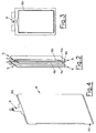
- Die Erfindung wird im Folgenden anhand der Figuren näher erläutert. Es zeigen:
- Fig. 1
- einen erfindungsgemäßen Energiespeicher in einer Schrägansicht;
- Fig. 2
- einen Stapel von Einzelzellen dieses Energiespeichers in einer Schrägansicht;
- Fig. 3
- den Stapel in einer Seitenansicht;
- Fig. 4
- ein Heiz- und Kühlelement in einer Schrägansicht;
- Fig. 5
- das Heiz- und Kühlelement in einer teilweise geschnittenen Schrägansicht; und
- Fig. 6
- das Heiz- und Kühlelement in einer weiteren Schrägansicht.
- Der elektrische Energiespeicher 1 beinhaltet zumindest einen Batteriemodul 2 mit einem Stapel 3 an Einzelzellen 4a, 4b aufweisenden Einzelmodulen 5, wobei an jedem Ende des Stapels jeweils eine Endplatte 6 angeordnet ist. Jeder Einzelmodul 5 weist einen Einzelzellrahmen 7 auf, wobei im Ausführungsbeispiel jeder Einzelzellenrahmen ein Zellenpaar 4 mit einer ersten und einer zweiten Einzelzelle 4a, 4b aufnimmt.
- Zwischen zwei benachbarten Zellen 4b und/oder zwischen zwei benachbarten Einzelmodulen 5 ist eine kombiniertes Heiz- und Kühleinheit 8 mit einem Heizelement 9 und einem Kühlelement 10 angeordnet.
- Das Heizelement wird durch eine dünne flexible Heizfolie 9a gebildet, welche Widerstandsdrähte 9b aufweisen kann. Durch die flexible Form ist eine Anpassung an verschiedene Oberflächen möglich. Das Heizelement 9a ist durch ein Kühlelement 10 aus beispielsweise gefaltetem Blech umschlossen und ist laserverschweißt. Somit bildet das Kühlelement an beiden Seiten des Heizelementes eine Kühlplatte 10a, 10b aus, welche an den Einzellzellen des Batteriemoduls 2 flächig anliegt. Die Heiz- und Kühleinheit 8 kann zwischen zwei Einzelzellenrahmen 7 eingeklemmt sein und somit maximal möglichen Oberflächenkontakt zu den anliegenden Einzelzellen 4b aufweisen. Die Wärmeabfuhr von den Kühlplatten 10a, 10b kann durch Luft- oder Flüssigkeitskühlung erfolgen. Gegebenenfalls können auch Peltierelemente zur Kühlung eingesetzt werden.
- Die Verbindung zwischen Kühlelement 10 und Heizelement 9 kann durch Kleben oder durch Formschluss erfolgen.
- Durch die extrem dünne und flache Ausführung benötigt die Heiz- und Kühleinheit 8 nur geringen Bauraum. Die vollflächige Auflage gewährleistet einen besonders guten Wärmeübergang.
Claims (12)
- Elektrischer Energiespeicher (1), insbesondere für Kraftfahrzeuge, mit zumindest einem Batteriemodul (2) mit einer Mehrzahl an zwischen zwei äuβeren Endplatten (6) in einem Stapel (3) angeordneten Einzelzellen (4a, 4b), dadurch gekennzeichnet, dass zwischen zumindest zwei Einzelzellen (4a, 4b) ein elektrisches Heizelement (9) angeordnet ist.
- Energiespeicher (1) nach Anspruch 1, wobei mindestens eine Einzelzelle (4a, 4b) in einem Einzelmodul (5) angeordnet ist, dadurch gekennzeichnet, dass das elektrische Heizelement (9) zwischen zwei Einzelmodulen (5) angeordnet ist.
- Energiespeicher (1) nach Anspruch 1 oder 2, dadurch gekennzeichnet, dass das Heizelement (9) durch eine Heizfolie (9a) gebildet ist.
- Energiespeicher (1) nach einem der Ansprüche 1 bis 3, dadurch gekennzeichnet, dass das Heizelement (9) zumindest teilweise von einem Kühlelement (10) umgeben ist.
- Energiespeicher (1) nach Anspruch 4, dadurch gekennzeichnet, dass das Kühlelement (10) durch zumindest eine Kühlplatte (10a, 10b) gebildet ist.
- Energiespeicher (1) nach Anspruch 5, dadurch gekennzeichnet, dass die Kühlplatte (10a, 10b) aus Blech gefertigt ist.
- Energiespeicher (1) nach einem der Ansprüche 4 bis 6, dadurch gekennzeichnet, dass das Kühlelement (10) um das Heizelement (9) gefaltet ist.
- Energiespeicher (1) nach einem der Ansprüche 4 bis 7, wobei jeder Einzelmodul (5) einen Einzelzellenrahmen (7) aufweist, dadurch gekennzeichnet, dass das Heiz- und Kühlelement (9, 10) zwischen den Einzelzellenrahmen (7) zweier benachbarter Einzelmodule (5) eingeklemmt ist und an den Einzelzellen (4a, 4b) anliegt.
- Energiespeicher (1) nach einem der Ansprüche 1 bis 8, dadurch gekennzeichnet, dass Kühl- und Heizelement (9, 10) miteinander verklebt sind.
- Energiespeicher (1) nach einem der Ansprüche 1 bis 9, dadurch gekennzeichnet, dass Kühl- und Heizelement (9, 10) miteinander formschlüssig verbunden sind.
- Energiespeicher (1) nach einem der Ansprüche 1 bis 10, dadurch gekennzeichnet, Heizelement (9) und Kühlelement (10) eine kombinierte Heiz- und Kühleinheit (8) ausbilden.
- Energiespeicher (1) nach einem der Ansprüche 1 bis 11, dadurch gekennzeichnet, dass das elektrische Heizelement (9) flexibel ausgebildet ist.
Applications Claiming Priority (2)
| Application Number | Priority Date | Filing Date | Title |
|---|---|---|---|
| ATA320/2011A AT511117B1 (de) | 2011-03-09 | 2011-03-09 | Elektrischer energiespeicher |
| PCT/EP2012/054030 WO2012120090A1 (de) | 2011-03-09 | 2012-03-08 | Elektrischer energiespeicher |
Publications (2)
| Publication Number | Publication Date |
|---|---|
| EP2684241A1 EP2684241A1 (de) | 2014-01-15 |
| EP2684241B1 true EP2684241B1 (de) | 2016-02-24 |
Family
ID=45815544
Family Applications (1)
| Application Number | Title | Priority Date | Filing Date |
|---|---|---|---|
| EP12708309.5A Not-in-force EP2684241B1 (de) | 2011-03-09 | 2012-03-08 | Elektrischer energiespeicher mit integrierter flexibler kühl-heizkombination |
Country Status (7)
| Country | Link |
|---|---|
| US (1) | US20140050964A1 (de) |
| EP (1) | EP2684241B1 (de) |
| JP (1) | JP6114201B2 (de) |
| KR (1) | KR101964779B1 (de) |
| CN (1) | CN103563145A (de) |
| AT (1) | AT511117B1 (de) |
| WO (1) | WO2012120090A1 (de) |
Families Citing this family (11)
| Publication number | Priority date | Publication date | Assignee | Title |
|---|---|---|---|---|
| DE102012111817B4 (de) | 2012-12-05 | 2024-02-01 | Dr. Ing. H.C. F. Porsche Aktiengesellschaft | Kraftfahrzeug |
| DE102013102867A1 (de) * | 2013-03-20 | 2014-10-09 | Dr. Ing. H.C. F. Porsche Aktiengesellschaft | Temperiervorrichtung |
| DE102014219812A1 (de) * | 2014-09-30 | 2016-03-31 | Robert Bosch Gmbh | Kühlplatte für einen elektrischen Energiespeicher |
| FR3047612B1 (fr) * | 2016-02-05 | 2018-03-16 | Safran Aircraft Engines | Pile a combustible et systeme de chauffage associe |
| DE102016121838A1 (de) | 2016-11-15 | 2018-05-17 | Dr. Ing. H.C. F. Porsche Aktiengesellschaft | Temperierelement für eine Batterie |
| DE102018211005B3 (de) | 2018-07-04 | 2019-04-18 | Bayerische Motoren Werke Aktiengesellschaft | Heizeinrichtung für eine prismatische Batteriezelle einer Hochvoltbatterie eines Kraftfahrzeugs, Batteriezelle, Batteriemodul, Hochvoltbatterie sowie Kraftfahrzeug |
| KR102479967B1 (ko) * | 2019-05-10 | 2022-12-20 | 주식회사 엘지에너지솔루션 | 전지 모듈 |
| DE102019133400A1 (de) * | 2019-12-06 | 2021-06-10 | Bayerische Motoren Werke Aktiengesellschaft | Elektrischer Energiespeicher für ein Kraftfahrzeug |
| JP7446187B2 (ja) * | 2020-09-07 | 2024-03-08 | ローム株式会社 | 加熱装置及び蓄電装置 |
| DE102021207402A1 (de) | 2021-07-13 | 2023-01-19 | Volkswagen Aktiengesellschaft | Hochvoltbatteriesystem |
| DE102023121520A1 (de) | 2023-08-11 | 2025-02-13 | Audi Aktiengesellschaft | Zwischenzellkühleinrichtung mit integrierter Heizeinrichtung, Batteriemodul und Kühleinrichtung für ein Batteriemodul |
Family Cites Families (19)
| Publication number | Priority date | Publication date | Assignee | Title |
|---|---|---|---|---|
| US6653002B1 (en) * | 1997-05-09 | 2003-11-25 | Ronald J. Parise | Quick charge battery with thermal management |
| CA2225585A1 (en) * | 1997-12-12 | 1999-06-12 | Hydro-Quebec | Battery control system |
| US7179554B2 (en) * | 2001-06-29 | 2007-02-20 | Plug Power Inc. | Fuel cell systems |
| DE60213474T2 (de) * | 2002-02-19 | 2007-03-15 | 3M Innovative Properties Co., St. Paul | Vorrichtung und verfahren zur temperaturkontrolle bei elektrochemischen zellen mit hoher energiedichte |
| JP2004171897A (ja) * | 2002-11-19 | 2004-06-17 | Sony Corp | 電源装置、及び電池の加温方法 |
| US7160640B2 (en) * | 2003-01-15 | 2007-01-09 | Ballard Power Systems Inc. | Fuel cell stack with passive end cell heater |
| US7531270B2 (en) * | 2006-10-13 | 2009-05-12 | Enerdel, Inc. | Battery pack with integral cooling and bussing devices |
| WO2008082399A1 (en) * | 2006-12-29 | 2008-07-10 | Utc Power Corporation | Heating element for a fuel cell |
| CN101675543B (zh) * | 2007-03-05 | 2013-05-01 | Temic汽车电机有限公司 | 带导热板的蓄能电池 |
| KR100980995B1 (ko) * | 2007-06-19 | 2010-09-07 | 현대자동차주식회사 | 연료전지용 지능형 전극막 |
| DE102008028400A1 (de) * | 2008-06-17 | 2009-12-24 | Behr Gmbh & Co. Kg | Vorrichtung zur Kühlung einer Fahrzeugbatterie |
| JP5077163B2 (ja) * | 2008-09-12 | 2012-11-21 | トヨタ自動車株式会社 | 蓄電装置 |
| JP4807595B2 (ja) * | 2008-12-12 | 2011-11-02 | 本田技研工業株式会社 | 電池保持装置 |
| JP5270326B2 (ja) * | 2008-12-17 | 2013-08-21 | プライムアースEvエナジー株式会社 | 組電池 |
| DE102009005853A1 (de) * | 2009-01-23 | 2010-07-29 | Li-Tec Battery Gmbh | Temperiertes Batteriesystem II |
| US9337456B2 (en) * | 2009-04-20 | 2016-05-10 | Lg Chem, Ltd. | Frame member, frame assembly and battery cell assembly made therefrom and methods of making the same |
| DE102010029872A1 (de) * | 2009-07-03 | 2011-01-05 | Visteon Global Technologies, Inc., Van Buren Township | Batteriebaugruppe für Hybrid- oder Elektrofahrzeuge |
| DE102010000267A1 (de) * | 2010-02-01 | 2011-08-04 | Clean Mobile AG, 82008 | Intelligente Temperaturregelung für eine Batterieheizung zum Aufheizen einer Fahrzeugbatterie auf eine Ladetemperatur |
| US20110206967A1 (en) * | 2010-02-25 | 2011-08-25 | Sanyo Electric Co., Ltd. | Battery cooling/heating structure and battery module |
-
2011
- 2011-03-09 AT ATA320/2011A patent/AT511117B1/de not_active IP Right Cessation
-
2012
- 2012-03-08 CN CN201280012034.1A patent/CN103563145A/zh active Pending
- 2012-03-08 WO PCT/EP2012/054030 patent/WO2012120090A1/de not_active Ceased
- 2012-03-08 JP JP2013557104A patent/JP6114201B2/ja active Active
- 2012-03-08 US US14/003,815 patent/US20140050964A1/en not_active Abandoned
- 2012-03-08 KR KR1020137024752A patent/KR101964779B1/ko not_active Expired - Fee Related
- 2012-03-08 EP EP12708309.5A patent/EP2684241B1/de not_active Not-in-force
Also Published As
| Publication number | Publication date |
|---|---|
| KR101964779B1 (ko) | 2019-04-02 |
| AT511117B1 (de) | 2014-11-15 |
| AT511117A1 (de) | 2012-09-15 |
| KR20140018904A (ko) | 2014-02-13 |
| CN103563145A (zh) | 2014-02-05 |
| JP6114201B2 (ja) | 2017-04-12 |
| EP2684241A1 (de) | 2014-01-15 |
| JP2014511553A (ja) | 2014-05-15 |
| WO2012120090A1 (de) | 2012-09-13 |
| US20140050964A1 (en) | 2014-02-20 |
Similar Documents
| Publication | Publication Date | Title |
|---|---|---|
| WO2012120090A1 (de) | Elektrischer energiespeicher | |
| EP2769426B1 (de) | Vorrichtung zur spannungsversorgung | |
| DE102006000885B3 (de) | Verfahren zur Herstellung eines Wärmetauscher-Rohrbündels für Wärmetauscher von elektrochemischen Energiespeichern | |
| EP2766941B1 (de) | Elektrischer energiespeicher | |
| EP2541669B1 (de) | Kühlvorrichtung für eine Fahrzeugbatterie, Fahrzeugbatterie sowie Verfahren zur Herstellung einer Kühlvorrichtung | |
| EP1944824B1 (de) | Elektrischer Energiespeicher | |
| EP2026387B1 (de) | Elektrochemische Energiespeichereinheit | |
| DE112007003042B4 (de) | Piezoelektrisches Ventil | |
| DE102010054070B4 (de) | Thermoelektrische Vorrichtung und thermoelektrisches Modul | |
| DE202012102349U1 (de) | Batteriekühler | |
| DE102008061755A1 (de) | Halte- und Kühlungsvorrichtung und Verfahren zur Herstellung einer Halte- und Kühlungsvorrichtung | |
| DE102016202375A1 (de) | Batteriezellenmodul mit kühlelement | |
| DE102008034875A1 (de) | Batterie, insbesondere Fahrzeugbatterie | |
| EP3167498B1 (de) | Trägeranordnung zum tragen und halten von komponenten für batteriezellen eines batteriemoduls, insbesondere für ein elektrisches fahrzeug | |
| EP2280422A2 (de) | Kühlelement für Solarzellenmodule | |
| EP2338189B1 (de) | Halte- und kühlungsvorrichtung und verfahren zur herstellung einer halte- und kühlungsvorrichtung | |
| DE102021116605A1 (de) | Elektrischer Energiespeicher für ein Kraftfahrzeug | |
| DE102015217790B4 (de) | Anordnung zur Kühlung von Batteriezellen eines Antriebsenergiespeichers eines Kraftfahrzeuges | |
| DE102016218140B4 (de) | Brennstoffzellenstapel mit Wärmerohren | |
| DE102012211653A1 (de) | Energiespeichermodul aus mehreren prismatischen Speicherzellen | |
| EP3942239A1 (de) | Kühlvorrichtung zum kühlen einer energiespeicher- und/oder elektronikbaugruppe sowie verfahren zu deren herstellung | |
| DE102009016573B4 (de) | Verfahren zum zusammenbauen einer batterie | |
| DE102013222130A1 (de) | Wärmeübertrager | |
| EP1926346B1 (de) | Elektrische Heizungsvorrichtung, insbesondere für ein Kraftfahrzeug | |
| WO2018215112A1 (de) | Temperierplatte |
Legal Events
| Date | Code | Title | Description |
|---|---|---|---|
| PUAI | Public reference made under article 153(3) epc to a published international application that has entered the european phase |
Free format text: ORIGINAL CODE: 0009012 |
|
| 17P | Request for examination filed |
Effective date: 20130823 |
|
| AK | Designated contracting states |
Kind code of ref document: A1 Designated state(s): AL AT BE BG CH CY CZ DE DK EE ES FI FR GB GR HR HU IE IS IT LI LT LU LV MC MK MT NL NO PL PT RO RS SE SI SK SM TR |
|
| 17Q | First examination report despatched |
Effective date: 20140116 |
|
| DAX | Request for extension of the european patent (deleted) | ||
| REG | Reference to a national code |
Ref country code: DE Ref legal event code: R079 Ref document number: 502012006049 Country of ref document: DE Free format text: PREVIOUS MAIN CLASS: H01M0008020000 Ipc: B60L0001080000 |
|
| GRAP | Despatch of communication of intention to grant a patent |
Free format text: ORIGINAL CODE: EPIDOSNIGR1 |
|
| RIC1 | Information provided on ipc code assigned before grant |
Ipc: H01M 8/04 20060101ALI20150904BHEP Ipc: H05B 3/34 20060101ALI20150904BHEP Ipc: B60L 11/18 20060101ALI20150904BHEP Ipc: H01M 10/655 20140101ALI20150904BHEP Ipc: B60L 1/08 20060101AFI20150904BHEP |
|
| INTG | Intention to grant announced |
Effective date: 20151014 |
|
| GRAS | Grant fee paid |
Free format text: ORIGINAL CODE: EPIDOSNIGR3 |
|
| GRAA | (expected) grant |
Free format text: ORIGINAL CODE: 0009210 |
|
| AK | Designated contracting states |
Kind code of ref document: B1 Designated state(s): AL AT BE BG CH CY CZ DE DK EE ES FI FR GB GR HR HU IE IS IT LI LT LU LV MC MK MT NL NO PL PT RO RS SE SI SK SM TR |
|
| REG | Reference to a national code |
Ref country code: GB Ref legal event code: FG4D Free format text: NOT ENGLISH |
|
| REG | Reference to a national code |
Ref country code: CH Ref legal event code: EP |
|
| REG | Reference to a national code |
Ref country code: AT Ref legal event code: REF Ref document number: 776497 Country of ref document: AT Kind code of ref document: T Effective date: 20160315 |
|
| REG | Reference to a national code |
Ref country code: IE Ref legal event code: FG4D Free format text: LANGUAGE OF EP DOCUMENT: GERMAN |
|
| REG | Reference to a national code |
Ref country code: DE Ref legal event code: R096 Ref document number: 502012006049 Country of ref document: DE |
|
| REG | Reference to a national code |
Ref country code: FR Ref legal event code: PLFP Year of fee payment: 5 |
|
| REG | Reference to a national code |
Ref country code: LT Ref legal event code: MG4D |
|
| REG | Reference to a national code |
Ref country code: NL Ref legal event code: MP Effective date: 20160224 |
|
| PG25 | Lapsed in a contracting state [announced via postgrant information from national office to epo] |
Ref country code: ES Free format text: LAPSE BECAUSE OF FAILURE TO SUBMIT A TRANSLATION OF THE DESCRIPTION OR TO PAY THE FEE WITHIN THE PRESCRIBED TIME-LIMIT Effective date: 20160224 Ref country code: HR Free format text: LAPSE BECAUSE OF FAILURE TO SUBMIT A TRANSLATION OF THE DESCRIPTION OR TO PAY THE FEE WITHIN THE PRESCRIBED TIME-LIMIT Effective date: 20160224 Ref country code: FI Free format text: LAPSE BECAUSE OF FAILURE TO SUBMIT A TRANSLATION OF THE DESCRIPTION OR TO PAY THE FEE WITHIN THE PRESCRIBED TIME-LIMIT Effective date: 20160224 Ref country code: GR Free format text: LAPSE BECAUSE OF FAILURE TO SUBMIT A TRANSLATION OF THE DESCRIPTION OR TO PAY THE FEE WITHIN THE PRESCRIBED TIME-LIMIT Effective date: 20160525 Ref country code: NO Free format text: LAPSE BECAUSE OF FAILURE TO SUBMIT A TRANSLATION OF THE DESCRIPTION OR TO PAY THE FEE WITHIN THE PRESCRIBED TIME-LIMIT Effective date: 20160524 |
|
| PG25 | Lapsed in a contracting state [announced via postgrant information from national office to epo] |
Ref country code: PT Free format text: LAPSE BECAUSE OF FAILURE TO SUBMIT A TRANSLATION OF THE DESCRIPTION OR TO PAY THE FEE WITHIN THE PRESCRIBED TIME-LIMIT Effective date: 20160624 Ref country code: LV Free format text: LAPSE BECAUSE OF FAILURE TO SUBMIT A TRANSLATION OF THE DESCRIPTION OR TO PAY THE FEE WITHIN THE PRESCRIBED TIME-LIMIT Effective date: 20160224 Ref country code: RS Free format text: LAPSE BECAUSE OF FAILURE TO SUBMIT A TRANSLATION OF THE DESCRIPTION OR TO PAY THE FEE WITHIN THE PRESCRIBED TIME-LIMIT Effective date: 20160224 Ref country code: PL Free format text: LAPSE BECAUSE OF FAILURE TO SUBMIT A TRANSLATION OF THE DESCRIPTION OR TO PAY THE FEE WITHIN THE PRESCRIBED TIME-LIMIT Effective date: 20160224 Ref country code: LT Free format text: LAPSE BECAUSE OF FAILURE TO SUBMIT A TRANSLATION OF THE DESCRIPTION OR TO PAY THE FEE WITHIN THE PRESCRIBED TIME-LIMIT Effective date: 20160224 Ref country code: SE Free format text: LAPSE BECAUSE OF FAILURE TO SUBMIT A TRANSLATION OF THE DESCRIPTION OR TO PAY THE FEE WITHIN THE PRESCRIBED TIME-LIMIT Effective date: 20160224 Ref country code: BE Free format text: LAPSE BECAUSE OF NON-PAYMENT OF DUE FEES Effective date: 20160331 Ref country code: NL Free format text: LAPSE BECAUSE OF FAILURE TO SUBMIT A TRANSLATION OF THE DESCRIPTION OR TO PAY THE FEE WITHIN THE PRESCRIBED TIME-LIMIT Effective date: 20160224 |
|
| PG25 | Lapsed in a contracting state [announced via postgrant information from national office to epo] |
Ref country code: DK Free format text: LAPSE BECAUSE OF FAILURE TO SUBMIT A TRANSLATION OF THE DESCRIPTION OR TO PAY THE FEE WITHIN THE PRESCRIBED TIME-LIMIT Effective date: 20160224 Ref country code: EE Free format text: LAPSE BECAUSE OF FAILURE TO SUBMIT A TRANSLATION OF THE DESCRIPTION OR TO PAY THE FEE WITHIN THE PRESCRIBED TIME-LIMIT Effective date: 20160224 |
|
| REG | Reference to a national code |
Ref country code: CH Ref legal event code: PL |
|
| REG | Reference to a national code |
Ref country code: DE Ref legal event code: R097 Ref document number: 502012006049 Country of ref document: DE |
|
| PG25 | Lapsed in a contracting state [announced via postgrant information from national office to epo] |
Ref country code: RO Free format text: LAPSE BECAUSE OF FAILURE TO SUBMIT A TRANSLATION OF THE DESCRIPTION OR TO PAY THE FEE WITHIN THE PRESCRIBED TIME-LIMIT Effective date: 20160224 Ref country code: SM Free format text: LAPSE BECAUSE OF FAILURE TO SUBMIT A TRANSLATION OF THE DESCRIPTION OR TO PAY THE FEE WITHIN THE PRESCRIBED TIME-LIMIT Effective date: 20160224 Ref country code: SK Free format text: LAPSE BECAUSE OF FAILURE TO SUBMIT A TRANSLATION OF THE DESCRIPTION OR TO PAY THE FEE WITHIN THE PRESCRIBED TIME-LIMIT Effective date: 20160224 Ref country code: CZ Free format text: LAPSE BECAUSE OF FAILURE TO SUBMIT A TRANSLATION OF THE DESCRIPTION OR TO PAY THE FEE WITHIN THE PRESCRIBED TIME-LIMIT Effective date: 20160224 |
|
| REG | Reference to a national code |
Ref country code: IE Ref legal event code: MM4A |
|
| PLBE | No opposition filed within time limit |
Free format text: ORIGINAL CODE: 0009261 |
|
| STAA | Information on the status of an ep patent application or granted ep patent |
Free format text: STATUS: NO OPPOSITION FILED WITHIN TIME LIMIT |
|
| PG25 | Lapsed in a contracting state [announced via postgrant information from national office to epo] |
Ref country code: IE Free format text: LAPSE BECAUSE OF NON-PAYMENT OF DUE FEES Effective date: 20160308 Ref country code: LI Free format text: LAPSE BECAUSE OF NON-PAYMENT OF DUE FEES Effective date: 20160331 Ref country code: CH Free format text: LAPSE BECAUSE OF NON-PAYMENT OF DUE FEES Effective date: 20160331 |
|
| 26N | No opposition filed |
Effective date: 20161125 |
|
| PG25 | Lapsed in a contracting state [announced via postgrant information from national office to epo] |
Ref country code: BG Free format text: LAPSE BECAUSE OF FAILURE TO SUBMIT A TRANSLATION OF THE DESCRIPTION OR TO PAY THE FEE WITHIN THE PRESCRIBED TIME-LIMIT Effective date: 20160524 Ref country code: SI Free format text: LAPSE BECAUSE OF FAILURE TO SUBMIT A TRANSLATION OF THE DESCRIPTION OR TO PAY THE FEE WITHIN THE PRESCRIBED TIME-LIMIT Effective date: 20160224 |
|
| REG | Reference to a national code |
Ref country code: FR Ref legal event code: PLFP Year of fee payment: 6 |
|
| PG25 | Lapsed in a contracting state [announced via postgrant information from national office to epo] |
Ref country code: MT Free format text: LAPSE BECAUSE OF FAILURE TO SUBMIT A TRANSLATION OF THE DESCRIPTION OR TO PAY THE FEE WITHIN THE PRESCRIBED TIME-LIMIT Effective date: 20160224 |
|
| REG | Reference to a national code |
Ref country code: FR Ref legal event code: PLFP Year of fee payment: 7 |
|
| REG | Reference to a national code |
Ref country code: AT Ref legal event code: MM01 Ref document number: 776497 Country of ref document: AT Kind code of ref document: T Effective date: 20170308 |
|
| PG25 | Lapsed in a contracting state [announced via postgrant information from national office to epo] |
Ref country code: HU Free format text: LAPSE BECAUSE OF FAILURE TO SUBMIT A TRANSLATION OF THE DESCRIPTION OR TO PAY THE FEE WITHIN THE PRESCRIBED TIME-LIMIT; INVALID AB INITIO Effective date: 20120308 Ref country code: CY Free format text: LAPSE BECAUSE OF FAILURE TO SUBMIT A TRANSLATION OF THE DESCRIPTION OR TO PAY THE FEE WITHIN THE PRESCRIBED TIME-LIMIT Effective date: 20160224 |
|
| PG25 | Lapsed in a contracting state [announced via postgrant information from national office to epo] |
Ref country code: IS Free format text: LAPSE BECAUSE OF FAILURE TO SUBMIT A TRANSLATION OF THE DESCRIPTION OR TO PAY THE FEE WITHIN THE PRESCRIBED TIME-LIMIT Effective date: 20160224 Ref country code: MK Free format text: LAPSE BECAUSE OF FAILURE TO SUBMIT A TRANSLATION OF THE DESCRIPTION OR TO PAY THE FEE WITHIN THE PRESCRIBED TIME-LIMIT Effective date: 20160224 Ref country code: LU Free format text: LAPSE BECAUSE OF NON-PAYMENT OF DUE FEES Effective date: 20160308 Ref country code: TR Free format text: LAPSE BECAUSE OF FAILURE TO SUBMIT A TRANSLATION OF THE DESCRIPTION OR TO PAY THE FEE WITHIN THE PRESCRIBED TIME-LIMIT Effective date: 20160224 Ref country code: MC Free format text: LAPSE BECAUSE OF FAILURE TO SUBMIT A TRANSLATION OF THE DESCRIPTION OR TO PAY THE FEE WITHIN THE PRESCRIBED TIME-LIMIT Effective date: 20160224 |
|
| PG25 | Lapsed in a contracting state [announced via postgrant information from national office to epo] |
Ref country code: AT Free format text: LAPSE BECAUSE OF NON-PAYMENT OF DUE FEES Effective date: 20170308 |
|
| PG25 | Lapsed in a contracting state [announced via postgrant information from national office to epo] |
Ref country code: AL Free format text: LAPSE BECAUSE OF FAILURE TO SUBMIT A TRANSLATION OF THE DESCRIPTION OR TO PAY THE FEE WITHIN THE PRESCRIBED TIME-LIMIT Effective date: 20160224 |
|
| PGFP | Annual fee paid to national office [announced via postgrant information from national office to epo] |
Ref country code: GB Payment date: 20200326 Year of fee payment: 9 Ref country code: IT Payment date: 20200330 Year of fee payment: 9 |
|
| PGFP | Annual fee paid to national office [announced via postgrant information from national office to epo] |
Ref country code: FR Payment date: 20200326 Year of fee payment: 9 |
|
| PGFP | Annual fee paid to national office [announced via postgrant information from national office to epo] |
Ref country code: DE Payment date: 20200528 Year of fee payment: 9 |
|
| REG | Reference to a national code |
Ref country code: DE Ref legal event code: R119 Ref document number: 502012006049 Country of ref document: DE |
|
| GBPC | Gb: european patent ceased through non-payment of renewal fee |
Effective date: 20210308 |
|
| PG25 | Lapsed in a contracting state [announced via postgrant information from national office to epo] |
Ref country code: GB Free format text: LAPSE BECAUSE OF NON-PAYMENT OF DUE FEES Effective date: 20210308 Ref country code: FR Free format text: LAPSE BECAUSE OF NON-PAYMENT OF DUE FEES Effective date: 20210331 Ref country code: DE Free format text: LAPSE BECAUSE OF NON-PAYMENT OF DUE FEES Effective date: 20211001 |
|
| PG25 | Lapsed in a contracting state [announced via postgrant information from national office to epo] |
Ref country code: IT Free format text: LAPSE BECAUSE OF NON-PAYMENT OF DUE FEES Effective date: 20210308 |