EP2682754B1 - Position adjustment method for movable unit in specimen analysis device, and specimen analysis device - Google Patents
Position adjustment method for movable unit in specimen analysis device, and specimen analysis device Download PDFInfo
- Publication number
- EP2682754B1 EP2682754B1 EP12753007.9A EP12753007A EP2682754B1 EP 2682754 B1 EP2682754 B1 EP 2682754B1 EP 12753007 A EP12753007 A EP 12753007A EP 2682754 B1 EP2682754 B1 EP 2682754B1
- Authority
- EP
- European Patent Office
- Prior art keywords
- position adjustment
- terminal device
- screen
- set value
- section
- Prior art date
- Legal status (The legal status is an assumption and is not a legal conclusion. Google has not performed a legal analysis and makes no representation as to the accuracy of the status listed.)
- Active
Links
- 238000000034 method Methods 0.000 title claims description 81
- 238000004458 analytical method Methods 0.000 title description 5
- 238000004891 communication Methods 0.000 claims description 62
- 238000005259 measurement Methods 0.000 claims description 44
- 230000008859 change Effects 0.000 claims description 14
- 238000012790 confirmation Methods 0.000 claims description 14
- 230000004044 response Effects 0.000 claims description 7
- 239000000523 sample Substances 0.000 description 96
- 239000003153 chemical reaction reagent Substances 0.000 description 55
- 230000007246 mechanism Effects 0.000 description 51
- 230000008569 process Effects 0.000 description 49
- 238000006243 chemical reaction Methods 0.000 description 18
- 230000005540 biological transmission Effects 0.000 description 14
- 238000012545 processing Methods 0.000 description 12
- 238000004590 computer program Methods 0.000 description 11
- 238000001514 detection method Methods 0.000 description 9
- 239000007788 liquid Substances 0.000 description 7
- 230000001360 synchronised effect Effects 0.000 description 7
- 238000012360 testing method Methods 0.000 description 7
- 239000000427 antigen Substances 0.000 description 6
- 102000036639 antigens Human genes 0.000 description 6
- 108091007433 antigens Proteins 0.000 description 6
- 238000005070 sampling Methods 0.000 description 5
- 230000000694 effects Effects 0.000 description 4
- 238000002347 injection Methods 0.000 description 4
- 239000007924 injection Substances 0.000 description 4
- 239000000758 substrate Substances 0.000 description 4
- 230000032258 transport Effects 0.000 description 4
- 239000008280 blood Substances 0.000 description 3
- 210000004369 blood Anatomy 0.000 description 3
- 230000003247 decreasing effect Effects 0.000 description 3
- 238000007599 discharging Methods 0.000 description 3
- 239000006249 magnetic particle Substances 0.000 description 3
- 238000003825 pressing Methods 0.000 description 3
- 230000006835 compression Effects 0.000 description 2
- 238000007906 compression Methods 0.000 description 2
- 239000012530 fluid Substances 0.000 description 2
- 238000012544 monitoring process Methods 0.000 description 2
- 239000000243 solution Substances 0.000 description 2
- 210000002700 urine Anatomy 0.000 description 2
- 208000005176 Hepatitis C Diseases 0.000 description 1
- AUYYCJSJGJYCDS-LBPRGKRZSA-N Thyrolar Chemical class IC1=CC(C[C@H](N)C(O)=O)=CC(I)=C1OC1=CC=C(O)C(I)=C1 AUYYCJSJGJYCDS-LBPRGKRZSA-N 0.000 description 1
- 238000007792 addition Methods 0.000 description 1
- 230000009118 appropriate response Effects 0.000 description 1
- 238000003556 assay Methods 0.000 description 1
- 239000007853 buffer solution Substances 0.000 description 1
- 238000005251 capillar electrophoresis Methods 0.000 description 1
- 238000012937 correction Methods 0.000 description 1
- 230000001419 dependent effect Effects 0.000 description 1
- 239000006185 dispersion Substances 0.000 description 1
- 238000006073 displacement reaction Methods 0.000 description 1
- 208000002672 hepatitis B Diseases 0.000 description 1
- 230000002452 interceptive effect Effects 0.000 description 1
- 238000002156 mixing Methods 0.000 description 1
- 239000000203 mixture Substances 0.000 description 1
- 238000012986 modification Methods 0.000 description 1
- 230000004048 modification Effects 0.000 description 1
- 230000003287 optical effect Effects 0.000 description 1
- 230000008439 repair process Effects 0.000 description 1
- 238000013207 serial dilution Methods 0.000 description 1
- 230000011664 signaling Effects 0.000 description 1
- 238000002798 spectrophotometry method Methods 0.000 description 1
- 239000005495 thyroid hormone Substances 0.000 description 1
- 229940036555 thyroid hormone Drugs 0.000 description 1
- 238000012546 transfer Methods 0.000 description 1
- 239000000439 tumor marker Substances 0.000 description 1
Images


Classifications
-
- G—PHYSICS
- G01—MEASURING; TESTING
- G01N—INVESTIGATING OR ANALYSING MATERIALS BY DETERMINING THEIR CHEMICAL OR PHYSICAL PROPERTIES
- G01N33/00—Investigating or analysing materials by specific methods not covered by groups G01N1/00 - G01N31/00
- G01N33/48—Biological material, e.g. blood, urine; Haemocytometers
- G01N33/50—Chemical analysis of biological material, e.g. blood, urine; Testing involving biospecific ligand binding methods; Immunological testing
- G01N33/53—Immunoassay; Biospecific binding assay; Materials therefor
-
- G—PHYSICS
- G01—MEASURING; TESTING
- G01N—INVESTIGATING OR ANALYSING MATERIALS BY DETERMINING THEIR CHEMICAL OR PHYSICAL PROPERTIES
- G01N35/00—Automatic analysis not limited to methods or materials provided for in any single one of groups G01N1/00 - G01N33/00; Handling materials therefor
- G01N35/10—Devices for transferring samples or any liquids to, in, or from, the analysis apparatus, e.g. suction devices, injection devices
- G01N35/1009—Characterised by arrangements for controlling the aspiration or dispense of liquids
- G01N35/1011—Control of the position or alignment of the transfer device
-
- G—PHYSICS
- G01—MEASURING; TESTING
- G01N—INVESTIGATING OR ANALYSING MATERIALS BY DETERMINING THEIR CHEMICAL OR PHYSICAL PROPERTIES
- G01N35/00—Automatic analysis not limited to methods or materials provided for in any single one of groups G01N1/00 - G01N33/00; Handling materials therefor
- G01N35/00584—Control arrangements for automatic analysers
- G01N35/00722—Communications; Identification
- G01N2035/00891—Displaying information to the operator
- G01N2035/0091—GUI [graphical user interfaces]
-
- G—PHYSICS
- G01—MEASURING; TESTING
- G01N—INVESTIGATING OR ANALYSING MATERIALS BY DETERMINING THEIR CHEMICAL OR PHYSICAL PROPERTIES
- G01N35/00—Automatic analysis not limited to methods or materials provided for in any single one of groups G01N1/00 - G01N33/00; Handling materials therefor
- G01N35/02—Automatic analysis not limited to methods or materials provided for in any single one of groups G01N1/00 - G01N33/00; Handling materials therefor using a plurality of sample containers moved by a conveyor system past one or more treatment or analysis stations
- G01N35/04—Details of the conveyor system
- G01N2035/0474—Details of actuating means for conveyors or pipettes
- G01N2035/0491—Position sensing, encoding; closed-loop control
-
- G—PHYSICS
- G01—MEASURING; TESTING
- G01N—INVESTIGATING OR ANALYSING MATERIALS BY DETERMINING THEIR CHEMICAL OR PHYSICAL PROPERTIES
- G01N35/00—Automatic analysis not limited to methods or materials provided for in any single one of groups G01N1/00 - G01N33/00; Handling materials therefor
- G01N35/00584—Control arrangements for automatic analysers
- G01N35/00722—Communications; Identification
- G01N35/00871—Communications between instruments or with remote terminals
Definitions
- the present invention relates to a position adjustment method for movable units in a sample analyzer which causes movable units to operate in order to perform measurement, and to the sample analyzer.
- Patent Literature 1 describes an analyzer including a sampling needle which aspirates a specimen from a specimen container at a predetermined position, an injection part into which a specimen aspirated by the sampling needle is discharged, and a control section which controls the sampling needle.
- the sampling needle according to Patent Literature 1 aspirates a specimen from a specimen container, moves to the position of the injection part, and discharges the aspirated specimen into the injection part. Since a visible mark is provided at a center portion of the injection part, the position of the sampling needle can be adjusted by performing a key operation with reference to this mark.
- Document EP 2 098 871 A2 describes a sample analyzer which enables to confirm the position of a pipette of dispensing section not depend on instruction directed a start of a position confirmation operation from the operator, and to prevent a pipette from being damaged or credibility of analysis results from declining.
- the sample analyzer comprises a pipette, a pipette moving mechanism and a position confirming member disposed at a position where the pipette can be moved by the pipette moving mechanism.
- the position confirming member comprises a space into which a tip end of the pipette can be inserted.
- the tip end of the pipette is moved by the pipette moving mechanism so as to be inserted into the space of the position confirming member.
- the sample analyzer stops the movement of the pipette and notifies that the pipette of the pipette moving mechanism has a problem.
- Document US 5 104 621 A describes an automated multi-purpose analytical chemistry processing center and laboratory work station having a movable table for supporting microtiter plates and other fluid receptacles, a movable arm, and a modular mobile pod affixed for reciprocal movement along the arm.
- the workstation combines into a single programmable system the capabilities for automation of a wide range of bioanalytical procedures including, not only sample pipetting, serial dilution, reagent additions, mixing, reaction timing and similar known manual procedures, but also programmable spectrophotometric measurements and other physical parameters, further processing based on these measurements and automatic data recording.
- the work station is adapted to transfer, dispense, and aspirate liquid from one location to another automatically in accordance with user programmed instructions.
- the work station is capable of measuring physical characteristics of selected samples and performing experimental assays in a closed loop manner in accordance with those measurements.
- Fluid is dispensed and aspirated using interchangeable modules having one or a selected plurality of nozzles. Affixed to the modules nozzles are disposable pipettor tips, which are automatically picked up by the pod and ejected by a tip edjector mechanism at the control of the user. Additional modules may be used to perform Measurement Functions.
- the work station is designed for interactive connection with a remote computer.
- Document US 6 584 430 B1 describes a system for monitoring the state and performance of an analysis device, such as a capillary electrophoresis instrument.
- the system includes software for operating the analysis device and system management software for monitoring the device, generating a report on the state of the device and selecting an appropriate response based on this report.
- the response can include altering the function of one or more parts of the device, or signaling the need for a repair to be performed, for example.
- the remote control method which is a remote control method for remote-controlling the clinical specimen processing device that processes a clinical specimen, is designed so that an image of the clinical specimen processing device is picked up by an image pickup device, and the image picked up by the image pickup device is supplied to a control apparatus located at a remote place from the clinical specimen processing device through a communication network so that the picked-up image is displayed on the control apparatus.
- Document JP 2001 091522 A describes a protrusion whose distance from the stop position of a probe on a track drawn by the probe is formed at a unit which is used as the stop position of the probe.
- the liquid dispensing device is provided with a rotation and movement mechanism which is moved from a reference position to a component in the horizontal direction.
- the liquid dispensing device is provided with an up-and-down movement mechanism which is moved to the vertical direction from the reference position and which has an abnormal-fall detection part used to detect the collision of a foreign body in a fall operation.
- the liquid dispensing device is provided with a control means by which a value obtained by subtracting the default value Pd(i) of a movement amount in the horizontal direction from the reference position from an adjustment set value Pset(i) is used as a temporary movement amount Pt(i), which repeats a rotation movement and the fall operation, which repeats the operation while the temporary movement amount is being increased by an adjustment amount, which detects the protrusion by using the abnormal-fall detection part due to the collision of the foreign body and which decides an operating amount up to every stop position.
- Document JP 7 114439 A describes a terminal equipment having such a structure that a band is provided to a small sized case main body and an operator A fits the main body to one arm B and the main body is carried, and the case main body is provided with an input mechanism having plural keys used to send various command signals to a controller controlling the operation of a mechanism section of a processing unit through a radio channel by the operation by the operator A, a display device and an alarm device.
- An object of the present invention is to provide a sample analyzer and a position adjustment method for a movable unit in a sample analyzer that allow easy position adjustment of a movable unit even when the place at which to perform a key operation and the movable unit on which to perform position adjustment are away from each other.
- a first aspect of the present invention relates to a position adjustment method for a movable unit in a sample analyzer which includes: a measurement section which causes a movable unit to operate in order to measure a sample; and a communication section for performing communication with outside.
- the position adjustment method for the movable unit in the sample analyzer includes: a terminal screen displaying step of causing a portable terminal device to display a position adjustment screen for accepting an input for changing a position of the movable unit, the portable terminal device configured to be able to perform communication with the communication section; an inputting step of performing the input for changing the position onto the position adjustment screen; a transmitting step of transmitting the input for changing the position performed onto the position adjustment screen, from the terminal device to the communication section; and a movement executing step of causing the measurement section to execute a movement of the corresponding movable unit in accordance with the input for changing the position received by the communication section.
- the position adjustment method for the movable unit in the sample analyzer according to this aspect, even when the movable unit is away from the position at which to operate the sample analyzer, by bringing the terminal device near the movable unit, it is possible to give instruction to change the position of the movable unit via the position adjustment screen displayed in the terminal device, while viewing the position of the movable unit. Therefore, when performing position adjustment of the movable unit, an operator need not come and go between the position at which to operate the sample analyzer and the movable unit, and can perform position adjustment of the movable unit very simply.
- the sample analyzer may include a storage section in which a set value regarding the position of the movable unit is stored
- the terminal screen displaying step may include: a step of generating image data for the position adjustment screen based on the set value stored in the storage section; and a step of transmitting the generated image data from the communication section to the terminal device. Accordingly, it is sufficient that the terminal device has a function for reproducing and displaying the received screen data. Thus, the terminal device need not have a special application for position adjustment installed therein. Thus, it is possible to perform position adjustment for a movable unit by using a general-purpose computer and a terminal device that uses a general-purpose application.
- the position adjustment method may further include a body screen displaying step of displaying the position adjustment screen based on the set value stored in the storage section, in a display section provided in the sample analyzer.
- the movement executing step may include a step of causing the measurement section to execute a movement of the corresponding movable unit, in accordance with an input for changing the set value onto the position adjustment screen displayed in the display section or the terminal device
- the body screen displaying step may include a step of updating the position adjustment screen displayed in the display section, based on the movement of the movable unit
- the terminal screen displaying step may include a step of updating the position adjustment screen displayed in the terminal device such that, in synchronization with the update of the position adjustment screen displayed in the display section, the updated position adjustment screen is also displayed in the terminal device.
- the terminal screen displaying step may include a step of, upon accepting a change of the set value, generating image data of a region in which the changed set value is displayed, the region being a part of the position adjustment screen, and of transmitting to the terminal device the generated image data along with data designating a region to be changed. Accordingly, it is sufficient that only the image data of the region regarding the change of the set value and the data designating the region may be transmitted to the terminal device. Thus, compared with a case where all of the image data of the position adjustment screen is transmitted to the terminal device when the set value is changed, the amount of the data to be transmitted to the terminal device can be significantly reduced.
- the position adjustment screen may include a movement key for moving the movable unit by a predetermined movement amount
- the movement executing step may include a step of moving the movable unit by the predetermined movement amount, every time the movement key in the position adjustment screen displayed in the terminal device is pressed. Accordingly, position adjustment for the movable unit can be performed through a simple operation.
- the measurement section includes a plurality of the movable units
- the terminal screen displaying step includes a step of causing the terminal device to display a selection accepting screen for accepting a selection of a movable unit targeted by position adjustment from among the plurality of the movable units, and of causing the terminal device to display the position adjustment screen for accepting a position adjustment instruction to the movable unit selected via the selection accepting screen.
- selection of a movable unit is performed on the terminal device side.
- the terminal screen displaying step causes an image showing the selected movable unit to be displayed on the selection accepting screen. Accordingly, it is possible to confirm at a glance where the adjustment target movable unit is located.
- the terminal screen displaying step may include a step of causing the terminal device to display an operation confirmation button for accepting an instruction for confirming an operation of the movable unit adjusted based on the input onto the position adjustment screen
- the movement executing step may include a step of causing, upon accepting an input onto the operation confirmation button, the movable unit to execute a movement from a predetermined origin position to an adjusted position. Accordingly, it is possible to confirm the adjusted state of the adjustment target movable unit.
- the terminal device may be configured to be able to perform wireless communication with the communication section.
- a second aspect of the present invention relates to a sample analyzer according to claim 9.
- the sample analyzer may further include a storage section in which a set value regarding the position of the movable unit is stored.
- the controller may generate image data for the position adjustment screen based on the set value stored in the storage section, and transmit the generated image data from the communication section to the terminal device.
- the sample analyzer may further include a display section.
- the controller may cause the display section to display the position adjustment screen based on the set value stored in the storage section.
- a sample analyzer and a position adjustment method for a movable unit in a sample analyzer that allow easy position adjustment of a movable unit even when the place at which to perform a key operation and a movable unit on which to perform position adjustment are away from each other.
- the present embodiment is realized by applying the present invention to an immunoanalyzer for performing tests for various items such as hepatitis B, hepatitis C, tumor marker, and thyroid hormone, using a sample such as blood.
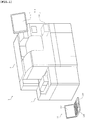
- FIG. 1 is a perspective view showing an overall configuration of an immunoanalyzer 1.
- the immunoanalyzer 1 includes a measurement mechanism section 2, a sample transporting section (sampler) 3, and a control device 4.
- the measurement mechanism section 2 is communicably connected to the sample transporting section 3 and the control device 4.
- the sample transporting section 3 is configured to be able to transport a rack in which a plurality of test tubes each containing a sample are placed.
- the control device 4 includes a body 400, and a display input section 410 implemented by a touch panel, and is capable of performing wireless communication with a terminal device 100.
- the terminal device 100 is used when performing position adjustment of various types of units in the measurement mechanism section 2, and includes a body 110, an input section 120, and a display section 130. Position adjustment performed in the measurement mechanism section 2 will be described later with reference to FIG. 6 and 7 .
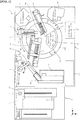
- FIG. 2 is a plan view showing a configuration of the inside of the immunoanalyzer 1, viewed from above.
- the measurement mechanism section 2 includes a sample dispensing arm 5, an R1 reagent dispensing arm 6, an R2 reagent dispensing arm 7, an R3 reagent dispensing arm 8, a reaction part 9, a cuvette supplying part 10, a primary BF separator 11, a secondary BF separator 12, a pipette tip supplying part 13, a detection part 14, an R4/R5 reagent supplying part 15, and a reagent setting part 16.
- the sample transporting section 3 is configured to be able to transport a rack in which a plurality of test tubes each containing an unprocessed sample are placed.
- a sample such as blood to be measured and a buffer solution (R1 reagent) are mixed together, and to the obtained mixture solution, a reagent (R2 reagent) is added which contains magnetic particles carrying a capture antibody to be bound to an antigen contained in the sample.
- a reagent R2 reagent
- a labeled antibody (R3 reagent) is further added thereto, and magnetic particles carrying the capture antibody bound to the labeled antibody and the antigen are attracted to a magnet (not shown) of the secondary BF separator 12, whereby the R3 reagent containing the labeled antibody that is unreacted is removed. Further, a dispersion liquid (R4 reagent) and a luminescent substrate (R5 reagent) which emits light in a reaction process with the labeled antibody are added. Then, the amount of light generated in the reaction between the labeled antibody and the luminescent substrate is measured. Through this process, the antigen contained in the sample bound to the labeled antibody is quantitatively measured.
- the cuvette supplying part 10 is configured to be able to accommodate a plurality of cuvettes, and sequentially supplies cuvettes one by one to a discharge position 1b for the sample dispensing arm 5.
- the R1 reagent dispensing arm 6 has a pipette 6a attached thereto for aspirating and discharging the R1 reagent.
- the R1 reagent dispensing arm 6 aspirates the R1 reagent set in the reagent setting part 16 by use of the pipette 6a, and dispenses (discharges) the aspirated R1 reagent into a cuvette placed at the discharge position 1b.
- the pipette tip supplying part 13 transports one by one a plurality of pipette tips (not shown) that have been fed thereinto, to a tip attaching position (not shown) for the sample dispensing arm 5. Thereafter, the pipette tip is attached to the tip of the pipette of the sample dispensing arm 5 at the tip attaching position.
- the sample dispensing arm 5 aspirates, by use of the attached pipette tip, the sample in a test tube transported to a sample aspiration position 1a by the sample transporting section 3. This aspiration is performed through a hole 31a formed in a top plate 31 which covers the transport path of the sample transporting section 3.
- the sample dispensing arm 5 dispenses (discharges) the aspirated sample into the cuvette at the discharge position 1b.
- the R1 reagent has been dispensed in advance by the R1 reagent dispensing arm 6.
- the cuvette is transferred to the reaction part 9 by means of a catcher not shown of the R1 reagent dispensing arm 6.
- the R2 reagent dispensing arm 7 has a pipette 7a attached thereto for aspirating and discharging the R2 reagent.
- the R2 reagent dispensing arm 7 aspirates the R2 reagent set in the reagent setting part 16 by use of the pipette 7a, and dispenses (discharges) the aspirated R2 reagent into the cuvette containing the R1 reagent and the sample.
- the reaction part 9 is formed in an annular shape so as to surround the reagent setting part 16 having a round shape. Further, the reaction part 9 includes a plurality of cuvette setting parts 9a arranged along the outline of the reaction part 9 at predetermined intervals. The cuvettes set in the cuvette setting part 9a are heated to about 42°C. Accordingly, the reaction between the sample and the various reagents in each cuvette is promoted. Further, the reaction part 9 is configured to be able to rotate in the clockwise direction (arrow A1 direction), and moves the respective cuvettes set in the cuvette setting parts 9a to their corresponding processing positions at which various types of processes (e.g., dispensing of a reagent) are performed.
- various types of processes e.g., dispensing of a reagent
- Each cuvette containing a sample, the R1 reagent, and the R2 reagent is transferred from the reaction part 9 to the primary BF separator 11 by means of a catcher not shown.
- the primary BF separator 11 removes components in the sample that are not bound to the capture antibody, from the specimen in the cuvette.
- the R3 reagent dispensing arm 8 has a pipette 8a attached thereto for aspirating and discharging the R3 reagent.
- the R3 reagent dispensing arm 8 aspirates the R3 reagent set in the reagent setting part 16 by use of the pipette 8a. Further, the R3 reagent dispensing arm 8 dispenses (discharges), by use of the pipette 8a, the aspirated R3 reagent into the cuvette which has been transferred to the reaction part 9 from the primary BF separator 11.
- the cuvette which contains the R3 reagent and the specimen after the removal process performed by the primary BF separator 11 is transferred from the reaction part 9 to the secondary BF separator 12 by means of a catcher not shown.
- the secondary BF separator 12 removes the R3 reagent containing the labeled antibody that is unreacted.
- the R4/R5 reagent supplying part 15 sequentially dispenses, by means of a tube not shown, the R4 reagent and the R5 reagent into the cuvette containing the specimen after the removal process performed by the secondary BF separator 12.
- the detection part 14 obtains, by means of a photo multiplier tube, light generated in the reaction process between the luminescent substrate and the labeled antibody bound to the antigen in the sample which has been subjected to predetermined processes, thereby measuring the amount of antigen contained in the sample.
- a cover 161 having a round shape is arranged so as to cover both the reagent setting part 16 and the reaction part 9. At predetermined positions of the cover 161, openings through which the R1 to R3 reagent dispensing arms aspirate reagents, and openings through which the R1 to R3 reagent dispensing arms perform movement of cuvettes and dispensing processes are formed.
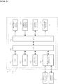
- FIG. 3 shows a circuit configuration of the measurement mechanism section 2.
- the measurement mechanism section 2 includes a control section 200, a stepping motor section 211, a rotary encoder section 212, a sensor section 213, and a mechanism section 214.
- the control section 200 includes a CPU 201, a ROM 202, a RAM 203, a battery backup RAM 204, a communication interface 205, and an 1/0 interface 206.
- the CPU 201 executes computer programs stored in the ROM 202 and computer programs loaded onto the RAM 203.
- the RAM 203 is used for reading out computer programs stored in the ROM 202, and is also used as a work area for the CPU 201 when the CPU 201 executes these computer programs.
- the battery backup RAM 204 is configured such that stored contents are not deleted even when the power source of the measurement mechanism section 2 is turned off. In the battery backup RAM 204, set values of each unit in the measurement mechanism section 2 are stored. The set values will be described later with reference to FIG. 6 .
- the communication interface 205 is connected to the sample transporting section 3 and the control device 4.
- the CPU 201 transmits to the control device 4 optical information (data of the amount of light generated in the reaction between the labeled antibody and the luminescent substrate) of the sample, and receives signals from the control device 4, via the communication interface 205. Further, the CPU 201 transmits a drive instruction signal to the sample transporting section 3 via the communication interface 205.
- the CPU 201 is connected to the stepping motor section 211, the rotary encoder section 212, the sensor section 213, and the mechanism section 214, via the I/O interface 206.
- the stepping motor section 211 includes stepping motors for respectively driving the units for performing processes in the measurement mechanism section 2. Each stepping motor is controlled by the CPU 201 via the I/O interface 206.
- the rotary encoder section 212 includes rotary encoders which respectively correspond to the stepping motors. Each rotary encoder outputs pulses by the number that corresponds to the amount of rotational displacement of its corresponding stepping motor. By counting the number of pulses outputted by each rotary encoder, the amount of rotation of its corresponding stepping motor can be detected. A detection signal of each rotary encoder is outputted to the CPU 201 via the I/O interface 206.
- the sensor section 213 includes a plurality of sensors which detect that the respective units in the measurement mechanism section 2 are at predetermined positions. By means of detection signals from these sensors, it is possible to know at which positions the units in the measurement mechanism section 2 are positioned.
- Each sensor is controlled by the CPU 201 via the I/O interface 206. Further, a detection signal of each sensor is outputted to the CPU 201 via the I/O interface 206.
- the mechanism section 214 includes other mechanisms included in the measurement mechanism section 2, and these mechanisms are controlled by the CPU 201 via the I/O interface 206.
- FIG. 4 shows a circuit configuration of the control device 4.
- the control device 4 is implemented by a personal computer, and includes the body 400 and the display input section 410.
- the body 400 includes a CPU 401, a ROM 402, a RAM 403, a hard disk 404, a readout device 405, an input/output interface 406, an image output interface 407, and a communication interface 408.
- the CPU 401 executes computer programs stored in the ROM 402 and computer programs loaded onto the RAM 403.
- the RAM 403 is used for reading out computer programs stored in the ROM 402 and the hard disk 404.
- the RAM 403 is also used as a work area for the CPU 401 when the CPU 401 executes these computer programs.
- various computer programs such as an operating system and application programs, to be executed by the CPU 401, and data used for execution of such computer programs are installed. That is, a program for displaying a position adjustment main screen 500 (see FIG. 6 ) and a fine adjustment screen 600 (see FIG. 7 ) for accepting a change of a set value of each unit in the measurement mechanism section 2 is installed. Moreover, a program for generating image data based on these screens, transmitting the generated image data to the terminal device 100, and rewriting a set value in accordance with a change of the set value received from the terminal device 100 is installed.
- the readout device 405 is implemented by a CD drive, a DVD drive, or the like, and can read out computer programs and data stored in a storage medium.
- the input/output interface 406 receives a signal outputted from the display input section 410.
- the image output interface 407 outputs a video signal corresponding to image data, to the display input section 410.
- the display input section 410 displays an image based on the video signal outputted from the image output interface 407, and outputs an instruction accepted from a user via the screen of the display input section 410, to the input/output interface 406.
- a key board image for accepting a numerical value input is displayed in the display input section 410. By pressing digits displayed on this image, the user can input a numerical value.
- the communication interface 408 transmits signals on the body 400 side to the measurement mechanism section 2 and the terminal device 100, and receives signals transmitted from the measurement mechanism section 2 and the terminal device 100.
- the terminal device 100 and the communication interface 408 are connected to each other so as to be able to perform wireless communication with each other.
- the communication interface 408 includes a wireless LAN card as a communication module.
- the wireless LAN card is configured to be able to perform wireless communication with a communication interface 118 of the terminal device 100 via a wireless LAN router not shown.
- This wireless LAN communication environment physical layers in the wireless communication between the terminal device 100 and the control device 4 are constructed. Establishment of an upper layer communication channel is realized by transmitting and receiving IP packets using a TCP/IP protocol via the wireless LAN router as described later.
- FIG. 5 shows a circuit configuration of the terminal device 100.
- the terminal device 100 is implemented by a notebook personal computer, and includes the body 110, the input section 120, and the display section 130.
- the body 110 includes a CPU 111, a ROM 112, a RAM 113, a hard disk 114, a readout device 115, an input/output interface 116, an image output interface 117, and the communication interface 118. Since the circuit configuration of the body 110 is substantially the same as the circuit configuration of the body 400 of the control device 4, description thereof is omitted here.
- the input section 120 is implemented by a touch pad and a key board. By the user operating the input section 120, an input signal is sent from the input section 120 to the input/output interface 116.
- the display section 130 is implemented by a display, and displays an image in accordance with image data outputted from the image output interface 117.
- the communication interface 118 transmits signals on the body 110 side to the control device 4 and receives signals transmitted from the control device 4.
- the control device 4 and the communication interface 118 are connected to each other so as to be able to perform wireless communication with each other.
- the communication interface 118 includes a wireless LAN card as a communication module for performing wireless communication.
- a program for displaying image data transmitted from the control device 4 and for transmitting a content inputted via the input section 120, to the control device 4 is installed.
- This program is not a dedicated program that controls position adjustments of the respective units in the measurement mechanism section 2 described later, but a general-purpose program for displaying received image and transmitting an inputted content.
- AIR of Adobe Systems Incorporated is installed as an execution environment, and applications executed in this execution environment can be installed.
- Programs executable in AIR are executable irrespective of the operating system as long as AIR is installed. Therefore, even if the operating system of the terminal device 100 is changed, it is not necessary to newly prepare programs to be executed in the terminal device 100.
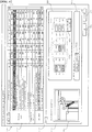
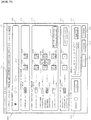
- FIG. 6 shows the position adjustment main screen 500 for performing position adjustment of each unit in the measurement mechanism section 2.
- the position adjustment main screen 500 is displayed in a synchronized manner in the display input section 410 of the control device 4 and the display section 130 of the terminal device 100 as described later. Accordingly, the user can perform an operation onto the position adjustment main screen 500, via either the display input section 410 or the input section 120. It should be noted that when the position adjustment main screen 500 is displayed, the respective units in the measurement mechanism section 2 are all positioned at their origin positions.
- the position adjustment main screen 500 includes a set value display region 510, a detail display region 520, an OK button 531, and a cancel button 532.
- the set value display region 510 is a region in which operation positions of the respective units in the measurement mechanism section 2 are displayed. As shown in FIG. 6 , the set value display region 510 includes a unit name item, an operation location item, and set value items ( ⁇ , ⁇ , r, x, y, z, x+, y+, and z+).
- the unit name item indicates a unit name of each unit arranged in the measurement mechanism section 2
- the operation location item indicates an operation position of each unit.
- Each set value item defines a moved position of the unit relative to its operation position as a specific numerical value (the number of pulses). That is, an origin position has been set for each unit, and each set value is the number of pulses to be outputted to a corresponding stepping motor in order to drive the unit from its origin position to its moved position.
- x, y, and z represent the numbers of pulses for driving a unit in the coordinate axes X, Y, and Z directions (see FIG. 2 ), respectively, which are set in the measurement mechanism section 2.
- ⁇ represents the number of pulses for rotating a unit about the Z axis.
- ⁇ represents, in a case where an operation location of a unit corresponds to a part of another mechanism that is rotatable about the Z axis, the number of pulses for rotating said another mechanism (hereinafter referred to as "receiving-side mechanism") about the Z axis.
- r represents, in a unit that expands and contracts, the number of pulses for driving the unit in the expanding/contracting direction.
- x+, y+, and z+ represent offset amounts of the set values x, y, and z, respectively. It should be noted that, among the set values of each operation location, the value of a set value item not used in defining a moved position of the corresponding unit is set to be 0.
- FIG. 6 shows a state where the operation location "2: sampler aspiration position" of "sample arm” is displayed in a reversed manner. It should be noted that “2: sampler aspiration position” corresponds to the sample aspiration position 1a in FIG. 2 .
- each set value item is stored in the battery backup RAM 204 of the measurement mechanism section 2, associated with its corresponding unit name item and operation location item.
- these pieces of information are read from the battery backup RAM 204, and the set value display region 510 is displayed as shown in FIG. 6 .
- the detail display region 520 includes an adjustment location display region 521, a coarse adjustment display region 522, and a fine adjustment display region 523.
- an image of the vicinity of the operation location displayed in the reversed manner in the set value display region 510, and an arrow pointing at the operation location are displayed.
- an image of the vicinity of the sample aspiration position 1a in FIG. 2 is displayed in the adjustment location display region 521. Accordingly, the user can confirm the operation location targeted by position adjustment with reference to the image.
- the coarse adjustment display region 522 includes a current value display region 522a, a preceding value display region 522b, and a preceding value button 522c.
- the current value display region 522a includes nine text boxes. In each text box, a corresponding set value displayed in the reversed manner in the set value display region 510 is displayed. The value displayed in a text box can be directly changed by the user. When the set value in a text box is changed, its corresponding set value in the set value display region 510 is also changed. It should be noted that the text box corresponding to a set value that does not define a moved position of the target unit is displayed in gray, and no input is allowed for the text box.
- the text boxes in the current value display region 522a corresponding to ⁇ , r, and y are displayed in gray as shown in FIG. 6 .
- preceding value display region 522b values (preceding values) at the preceding adjustment of the respective set value items displayed in the reversed manner in the set value display region 510 are displayed.
- Such preceding values are read from the battery backup RAM 204 when display of the position adjustment main screen 500 is started, and are displayed in the preceding value display region 522b.
- each set value is written in the battery backup RAM 204, its current value and its preceding value are written. It should be noted that, at the shipment, default values are written as the current value and the preceding value.
- the preceding value button 522c is pressed, the preceding values displayed in the preceding value display region 522b are written in the text boxes in the current value display region 522a, respectively.
- the fine adjustment display region 523 includes a fine adjustment button 523a.
- the fine adjustment button 523a When the fine adjustment button 523a is pressed, the fine adjustment screen 600 (see FIG. 7 ) described later is displayed. That is, the user performs coarse adjustment of an operation position by inputting a specific numerical value in the coarse adjustment display region 522, and when the user wishes to perform fine adjustment, the user presses the fine adjustment button 523a.
- a check box 524 is checked by the user when adjustment for the operation location displayed in the reversed manner in the set value display region 510 is completed. Accordingly, the color of the corresponding operation location item and set value items is changed. In FIG. 6 , the color of the operation location "11: R1 reagent dispensing position" has been changed. Even when another operation location item is selected after the check box 524 is checked, the operation location item and set value items whose color has been changed will maintain the same color. Accordingly, the user can confirm the operation location on which position adjustment has been completed.
- FIG. 7 shows the fine adjustment screen 600.
- the fine adjustment screen 600 is also displayed in a synchronized manner in the display input section 410 of the control device 4 and the display section 130 of the terminal device 100. Accordingly, the user can perform an operation onto the fine adjustment screen 600, via either the display input section 410 or the input section 120.
- the fine adjustment screen 600 includes an adjustment location display region 601, a pulse movement value display region 610, a reaction cooler position adjustment display region 620, a unit position adjustment display region 630, a catcher position adjustment display region 640, a tip-of-pipette display region 650, a sensor display region 660, a state display region 671, a confirmation button 672, an OK button 673, and a cancel button 674.
- the adjustment location display region 601 a unit targeted by fine adjustment and an operation location of the unit are displayed. That is, the operation location displayed in the reversed manner in the set value display region 510 when the fine adjustment button 523a shown in FIG. 6 is pressed and the unit that includes the operation location are displayed in the adjustment location display region 601.
- the pulse movement value display region 610 includes three selectable radio buttons.
- the number assigned to each radio button represents the number of pulses that drive the unit when one of movement buttons 621b 621c, 631b to 634b, 631c to 634c, 641b, and 641c described later is pressed once.
- the user can set a unit of movement to be used during fine adjustment, by selecting any one of the radio buttons.
- positions in the up/down direction and the expanding/contracting direction of the unit are not moved to the positions defined by the values of z and r.
- Positions in the up/down direction and the expanding/contracting direction are moved to the positions defined by the values of z and r, by pressing movement auxiliary buttons 634d and 641d described later. Accordingly, unintentional collision of the unit against another mechanism in the apparatus can be prevented.
- the receiving-side mechanism corresponding to the unit displayed in the adjustment location display region 601 is rotated clockwise or counterclockwise, respectively, by the amount corresponding to the pulse movement value set in the pulse movement value display region 610. Associated with this, the value in the text label 621a is increased or decreased.
- the receiving-side mechanism the sample transporting section 3
- the text label 621a is displayed in gray. In this case, even if the movement button 621b or 621c is pressed, no change is made in the receiving-side mechanism (the sample transporting section 3).
- the movement buttons 631b or 631c, the movement buttons 632b or 632c, the movement buttons 633b or 633c, or the movement buttons 634b or 634c in the unit position adjustment display region 630 is pressed once, the unit is moved clockwise, counterclockwise, rightward, leftward, forward, backward, downward, or upward, respectively, and associated with this, the corresponding value of the text labels 631a to 634a is increased or decreased.
- the movement buttons 634b and 634c become active when the movement auxiliary button 634d is pressed. In the example shown in FIG. 7 , since the sample arm (the sample dispensing arm 5 in FIG.
- the text label 633a is displayed in gray. In this case, even if the movement button 633b or 633c is pressed, no change is made in the sample arm.
- the unit When the movement auxiliary button 634d is pressed by the user, the unit is positioned at the position in the up/down direction indicated in the text label 634a. When the movement auxiliary button 634d is pressed again, the unit is positioned at its origin position.
- the movement button 641b or 641c in the catcher position adjustment display region 640 When the movement button 641b or 641c in the catcher position adjustment display region 640 is pressed, the unit is moved in the expanding/contracting direction, and associated with this, the value of the text label 641a is increased or decreased. It should be noted that the movement buttons 641b and 641c become active when the movement auxiliary button 641d is pressed. In the example shown in FIG. 7 , since the sample arm (the sample dispensing arm 5 in FIG. 2 ) being the adjustment target unit does not expand or contract at the sampler aspiration position (the sample aspiration position 1a in FIG. 2 ) being the adjustment location, the text label 641a is displayed in gray. In this case, even if the movement button 641b or 641c is pressed, no change is made in the sample arm.
- the unit When the movement auxiliary button 641d is pressed by the user, the unit is expanded or contracted to the position shown in the text label 641a. When the movement auxiliary button 641d is pressed again, the unit is positioned at its origin position.
- the tip-of-pipette display region 650 includes a circular region for indicating a detection signal of a sensor which detects that the tip of the pipette has been brought into contact with a liquid surface, and a button for resetting the indication of this region.
- the sensor display region 660 includes six regions for respectively indicating detection signals of sensors relating to the unit displayed in the adjustment location display region 601, a button for causing execution of reading a bar code when these sensors include a bar code reader, and a text label for displaying the value of the read bar code.
- the unit displayed in the adjustment location display region 601 is returned to its origin position once, and then, the unit is moved to the adjustment location defined by ⁇ , ⁇ , x, y, z, and r. Accordingly, by viewing the unit being actually driven, the user can confirm whether the position adjustment performed via the fine adjustment screen 600 is appropriate.
- the fine adjustment screen 600 is closed, and the position adjustment main screen 500 in FIG. 6 is displayed.
- the set values that have been displayed in the text labels 621a, 631a to 634a, and 641a are reflected in the set value display region 510 of the position adjustment main screen 500 and in the current value display region 522a.
- the cancel button 674 is pressed, the contents set on the fine adjustment screen 600 are discarded, and the fine adjustment screen 600 is closed.
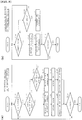
- FIG. 8 shows a flow chart of processes performed by the terminal device 100 and the control device 4, respectively.
- the CPU 111 of the terminal device 100 transmits a connection request to the control device 4 via the communication interface 118, first (S11). Specifically, the user designates an IP address of the control device 4 via the input section 120 of the terminal device 100, and inputs an instruction to try to establish communication with the control device 4. When the instruction is inputted, the communication interface 118 transmits an IP packet via the wireless LAN router (not shown) to the designated IP address. When a response to this is received from the control device 4, a wireless communication channel is established between the terminal device 100 and the control device 4. The communication between the terminal device 100 and the control device 4 thereafter is performed through transmission and reception of IP packets therebetween using a TCP/IP protocol.
- the CPU 111 starts a reception process and a transmission process (S12, S13).
- the CPU 111 causes the display section 130 to display a screen based on data received from the control device 4.
- the CPU 111 transmits the inputted information to the control device 4 in the transmission process.
- the processes started at S12 and S13 are repeated until a shutdown instruction is issued (S14).
- the reception process and the transmission process of the terminal device 100 will be described later with reference to FIG. 9(a) and (b) .
- the CPU 401 of the control device 4 prepares for accepting connection from the terminal device 100, first (S21), and causes the processing to wait until receiving a connection request from the terminal device 100 (S22). Upon receiving the connection request from the terminal device 100 via the communication interface 408 (S22: YES), the CPU 401 transmits a response to this to the terminal device 100. As a result, a wireless communication channel is established between the terminal device 100 and the control device 4.
- the CPU 401 starts a transmission process and a reception process (S23, S24).
- the CPU 401 transmits data to the terminal device 100 in the transmission process and receives, in the reception process, data transmitted from the terminal device 100.
- the processes stared at S23 and S24 are repeated until a shutdown instruction is issued (S25).
- the transmission process and the reception process of the control device 4 will be described later with reference to FIG. 10(a) and (b) .
- reception process and the transmission process of the terminal device 100 and the reception process and the transmission process of the control device 4 are respectively performed in parallel with each other.
- image data information indicating a position (a coordinate position on the screen) and a region (the size of a region originating at the coordinate position) for displaying an image
- discernment information indicating whether the image data is for displaying an image of the entire screen or for displaying a part of the screen are transmitted from the control device 4 to the terminal device 100.
- the terminal device 100 displays an image based on the image data so as to fit in the designated region (size), at the designated position (coordinates). Further, information indicating an input position (a coordinate position on the screen) on the screen displayed on the terminal device 100 or an inputted content (key information) is transmitted from the terminal device 100 to the control device 4.
- the terminal device 100 has a function of reproducing received image data as an image at the designated position and region, and a function of transmitting an input position (coordinate position) on the screen and an inputted content (key information).
- Such functions can be realized, for example, by installing a general-purpose program in the terminal device 100 as described above.
- FIG. 9(a) is a flow chart showing the reception process performed by the terminal device 100.
- the CPU 111 of the terminal device 100 determines whether the received data includes image data of the entire screen or image data of a part of the screen (S102, S106). Such determination is performed based on the above-described discernment information included in the received data.
- the processing is returned to S101.
- the CPU 111 obtains information of the entire screen (image data and information regarding a display size of this image) from the received data (S103).
- image data transmitted from the control device 4 to the terminal device 100 is in a compressed format (e.g., PNG format) in order to reduce the file size.
- the CPU 111 expands the obtained screen data into a format used before the compression (S104), and displays the expanded image on the display section 130 in the designated size. Accordingly, the entire screen of the display section 130 is updated (S105).
- the CPU 111 obtains update information (image data of the part of the screen, and the size of a region for displaying this image, and a coordinate position on the screen of this region) from the received data (S107). Subsequently, the CPU 111 expands the obtained image data into a format used before the compression (S108), and displays an image based on this image data in the region having the designated size at the designated coordinate position. Accordingly, the part of the screen of the display section 130 is updated (S109). For example, only the region corresponding to the text label 632a in FIG. 7 is updated. In this manner, the processes of S101 to 109 are repeated until a shutdown instruction is issued (S110).
- FIG. 9(b) is a flow chart showing the transmission process performed by the terminal device 100.
- the CPU 111 of the terminal device 100 obtains coordinates of the clicked position (S112) and transmits click information including these coordinates to the control device 4 (S113).
- the CPU 111 transmits to the control device 4 key information corresponding to the key on which the input has been performed (S115). In this manner, the processes of S111 to 115 are repeated until a shutdown instruction is issued (S116).
- FIG. 10(a) is a flow chart showing the transmission process performed by the control device 4.
- the CPU 401 of the control device 4 determines whether it is necessary to transmit image data of the entire screen (S201), and further determines whether it is necessary to transmit image data of a part of the screen (S204).
- the CPU 401 determines that it is necessary to transmit image data of the entire screen (S201: YES).
- the CPU 401 determines that it is necessary to transmit image data of a part of the screen (S204: YES).
- the CPU 401 Upon determining that it is necessary to transmit an image of the entire screen (S201: YES), the CPU 401 obtains image data of the entire screen and a display size of this image (S202), and compresses the image data, among these, into a predetermined format (S203). On the other hand, upon determining that it is necessary to transmit image data of a part of the screen (S201: NO, S204: YES), the CPU 401 obtains image data of a region (hereinafter referred to as a "change region”) corresponding to the changed portion in the screen, the size of the change region, and the coordinate position on the screen of the change region (S205), and compresses the image data, among these, into a predetermined format (S206).
- a region hereinafter referred to as a "change region”
- the CPU 401 transmits, to the terminal device 100, information of the entire screen including the image data compressed in S203 and the display size of the image, or update information including the image data compressed in S206 and the size and the coordinate position of the change region (S207).
- each of the information of the entire screen and the update information further includes discernment information indicating whether the image data is data regarding an image of the entire screen or regarding an image of a part of the screen.
- FIG. 10(b) is a flow chart showing the reception process performed by the control device 4.
- the CPU 401 of the control device 4 determines whether the received data is data regarding a screen click or a key input (S212, S215). When the received data is data regarding neither a screen click nor a key input (S212: NO, S215: NO), the processing is returned to S211.
- the CPU 401 obtains coordinates included in this data (S213). Subsequently, based on the obtained coordinates, the CPU 401 performs a "control process" (S214). The control process will be described later with reference to FIGS. 11 and 12 .
- the CPU 401 obtains key information included in this data (S216). Subsequently, based on this key information, the CPU 401 updates the text displayed in the display input section 410 (S217). Typically, at the timing when key information is received, a region into which text can be inputted, such as a text box on the screen, has been focused as a result of a click made onto the screen therebefore. In S217, based on the obtained information, the CPU 401 updates the display in such a focused region. When a region into which text can be inputted has not been focused at the timing of the process of S217, the CPU 401 invalidates the obtained text information.
- the CPU 401 updates the screen (the position adjustment main screen 500 or the fine adjustment screen 600) on the display input section 410, accordingly (S218).
- the determination in S201 or S204 in FIG. 10(a) becomes YES, and information for updating the screen is transmitted to the terminal device 100. Accordingly, the screen on the display input section 410 and the screen on the display section 130 on the terminal device 100 side are updated in a synchronized manner. In this manner, the processes of S211 to S218 are repeated until a shutdown instruction is issued (S219).
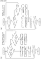
- FIG. 11 is a flow chart showing major processes of S214 (the control process) in FIG. 10 .
- the CPU 401 of the control device 4 determines whether the screen determined as having been clicked in S212 in FIG. 10(b) is the position adjustment main screen 500 (S301). When this screen is not the position adjustment main screen 500 (S301: NO), that is, this screen is the fine adjustment screen 600, the processing is advanced to a terminal A. When the clicked screen is the position adjustment main screen 500 (S301: YES), the CPU 401 performs the following processes based on the coordinates (place clicked by the user) obtained in S213 in FIG. 10(b) .
- the CPU 401 causes the items of the set values of this operation location to be displayed in a reversed manner (S309), and causes the set values of the clicked operation location to be displayed in the coarse adjustment display region 522 (S310). That is, in the current value display region 522a, the set values in the set value display region 510 are displayed, and in the preceding value display region 522b, the set values of this operation location at the time when the position adjustment main screen 500 was displayed are displayed.
- the CPU 401 changes the color of the items of the operation location and the set values, in the set value display region 510, which correspond to the display in the detail display region 520 (S311). It should be noted that, when nothing is displayed in the detail display region 520 as in the case where the position adjustment main screen 500 is opened for the first time, the determination in S303 is NO even if the check box 524 is clicked.
- the CPU 401 displays a cursor in the text box at the clicked place (S312).
- the CPU 401 replaces the values in the text boxes in the current value display region 522a with the corresponding values in the preceding value display region 522b (S313).
- the CPU 401 When the clicked place is the OK button 531 (S302 to S306: NO, S307: YES), the CPU 401 writes the set values displayed in the set value display region 510 into the battery backup RAM 204 (S315). Subsequently, the CPU 401 closes the position adjustment main screen 500 (S316).
- the clicked place is none of the above regions (S302 to S308: NO), the processes are not performed and the control process ends.
- the CPU 401 updates, in the process step of S218 in FIG. 10(b) , the screen (the position adjustment main screen 500 or the fine adjustment screen 600) on the display input section 410, in accordance with the update content of the corresponding one of S309 to S314 and S316.
- the determination in S201 or S204 in FIG. 10(a) becomes YES, and information for updating the screen is transmitted from the control device 4 to the terminal device 100. Accordingly, the screen on the display input section 410 of the control device 4 and the screen on the display section 130 on the terminal device 100 side are updated in a synchronized manner.
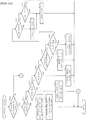
- FIG. 12 is a flow chart showing major processes after the terminal A in FIG. 11 .
- the CPU 401 of the control device 4 performs the following processes, based on the coordinates (the place clicked by the user) obtained in S213 in FIG. 10(b) .
- the CPU 401 updates the radio button at the clicked place to a selected state (S408). Simultaneously, the CPU 401 sets the unit of movement used when a movement button is pressed, to the number of pulses corresponding to the selected radio button.
- the CPU 401 moves the unit displayed in the adjustment location display region 601 (S409).
- drive pulses are outputted by the number of pulses selected in the pulse movement value display region 610, to a corresponding stepping motor in the stepping motor section 211.
- the CPU 401 updates the one of the text labels 621a, 631a to 634a, and 641a that corresponds to the drive, in accordance with the drive amount (S410).
- the clicked place is a movement button that corresponds to a text label displayed in gray, the determination in S402 is NO.
- the CPU 401 When the clicked place is a button other than the above (the button in the tip-of-pipette display region 650 or the button in the sensor display region 660) (S401 to S404: NO, S405: YES), the CPU 401 performs the corresponding operation and updates the corresponding information (S413).
- the CPU 401 maintains the set values displayed in the fine adjustment screen 600 (S414). Subsequently, the CPU 401 returns the unit displayed in the adjustment location display region 601 to its origin position (S415), and closes the fine adjustment screen 600 (S416).
- the CPU 401 discards the set values displayed in the fine adjustment screen 600 (S417). Subsequently, the CPU 401 returns the unit displayed in the adjustment location display region 601 to its origin position (S415), and closes the fine adjustment screen 600 (S416).
- the CPU 401 updates, in the process step of S218 in FIG. 10(b) , the screen (the position adjustment main screen 500 or the fine adjustment screen 600) on the display input section 410, in accordance with the update content of the corresponding one of S408, S410, S413, and S416.
- the screen is updated in this manner, the determination in S201 or S204 in FIG. 10(a) becomes YES, and information for updating the screen is transmitted from the control device 4 to the terminal device 100. Accordingly, the screen on the display input section 410 of the control device 4 and the screen on the display section 130 on the terminal device 100 side are updated in a synchronized manner.
- S211 is omitted from the flow chart in FIG. 10(b)
- S212 and S215 it is determined whether a click and a key input have been performed on the screen displayed in the display input section 410, respectively.
- S213 and S216 based on the input onto the display input section 410, coordinates of the clicked position and key information are obtained.
- the other processes are the same as those in the above embodiment.
- the determination in S201 or S204 in FIG. 10(a) becomes YES, and information for updating the screen is transmitted from the control device 4 to the terminal device 100. Accordingly, the screen on the display input section 410 of the control device 4 and the screen on the display section 130 on the terminal device 100 side are updated in a synchronized manner.
- the present embodiment even when the unit on which to perform position adjustment is away from the control device 4, by bringing the terminal device 100 near the unit, it is possible to give instruction to change set values of the unit via the position adjustment main screen 500 and the fine adjustment screen 600 displayed on the terminal device 100, while viewing the position of the unit. Therefore, when performing position adjustment of the unit, the user need not come and go between the position at which to operate the control device 4 and the unit, and can perform position adjustment of the unit very simply.
- the screen on the display section 130 is displayed based on the data regarding the screen transmitted from the control device 4, and the information inputted via the input section 120 is transmitted to the control device 4.
- a program for realizing such functions is installed in the terminal device 100. Therefore, the terminal device 100 need not have a special application for position adjustment installed therein, and thus, the terminal device 100 can be configured using a general-purpose computer and a general-purpose application. Accordingly, the terminal device 100 can be configured at a low cost and in a simple manner.
- the user by pressing an operation location item in the set value display region 510, the user can select a unit on which to perform position adjustment.
- the adjustment location display region 521 an image of the vicinity of the operation location of the selected unit, and an arrow indicating the operation location are shown. Accordingly, the user can confirm at a glance where the unit on which to perform position adjustment is located.
- an adjustment position of the unit can be set to a predetermined position via the coarse adjustment display region 522 of the position adjustment main screen 500 in a simple manner. Further, when a movement button is pressed on the fine adjustment screen 600, the adjustment position of the unit can be finely set. In addition, when performing setting using a movement button, the unit actually moves in accordance with the movement button. Therefore, the user can perform an appropriate position adjustment while confirming the moved position of the unit.
- the adjustment target unit when the confirmation button 672 is pressed, the adjustment target unit is moved from its origin position to the position defined by set values. Accordingly, the user can confirm whether the set values that have been set are appropriate, while viewing the unit being driven.
- a subject to be measured is exemplified by blood, but a subject to be measured may be urine. That is, the present invention can be applied to a specimen analyzer which tests urine, and further, the present invention can be applied to a clinical sample testing apparatus which tests other clinical samples.
- the set values of each unit in the measurement mechanism section 2 are stored in the battery backup RAM 204.
- the set values may be stored in the hard disk 404 of the control device 4 or the hard disk 114 of the terminal device 100.
- screen data generated in the control device 4 is transmitted to the terminal device 100.
- the terminal device 100 may generate screen data, and the screen data generated in the terminal device 100 may be transmitted to the control device 4.
- the same application program as that installed in the control device 4 is installed in the terminal device 100, and an instruction of position adjustment may be issued from the terminal device 100 to the measurement mechanism section 2, not via the control device 4.
- two screens i.e., the position adjustment main screen 500 and the fine adjustment screen 600
- the present invention is not limited thereto. Only one screen may be used, or three or more screens may be used.
- components of the position adjustment main screen 500 and the fine adjustment screen 600 may be arranged on one screen. Further, another screen on which only the coarse adjustment display region 522 of the position adjustment main screen 500 is displayed may be separately prepared.
- a notebook personal computer is used as the terminal device 100 of a portable type.
- the present invention is not limited thereto. Any terminal device that can be carried by a person may be used as the terminal device 100.
- a personal digital assistance (PDA) or a smart phone may be used.
- the terminal device 100 and the control device 4 are communicably connected to each other through wireless connection.
- the terminal device 100 and the control device 4 may be communicably connected to each other through wired connection. Wired communication may be realized, for example, by connecting the control device 4 and the terminal device 100 to each other with a LAN cable and using a TCP/IP protocol.
- a straight cable may be used to connect the control device 4 and the terminal device 100 via a hub, or a cross cable may be used to directly connect them.
- an application executed on AIR of Adobe Systems Incorporated is installed in the hard disk 114 of the terminal device 100.
- the present invention is not limited thereto. It is sufficient that a program that allows the control device 4 and the terminal device 100 to display the same screen in a synchronized manner is installed. For example, "pcAnywhere" of Symantec Corporation or "Remote Desktop” of Microsoft Corporation may be used.
Landscapes
- Health & Medical Sciences (AREA)
- Life Sciences & Earth Sciences (AREA)
- Immunology (AREA)
- Chemical & Material Sciences (AREA)
- Engineering & Computer Science (AREA)
- Pathology (AREA)
- General Physics & Mathematics (AREA)
- General Health & Medical Sciences (AREA)
- Biochemistry (AREA)
- Analytical Chemistry (AREA)
- Physics & Mathematics (AREA)
- Urology & Nephrology (AREA)
- Molecular Biology (AREA)
- Hematology (AREA)
- Biomedical Technology (AREA)
- Food Science & Technology (AREA)
- Medicinal Chemistry (AREA)
- Microbiology (AREA)
- Cell Biology (AREA)
- Biotechnology (AREA)
- Automatic Analysis And Handling Materials Therefor (AREA)
Applications Claiming Priority (2)
| Application Number | Priority Date | Filing Date | Title |
|---|---|---|---|
| JP2011042571A JP5745893B2 (ja) | 2011-02-28 | 2011-02-28 | 検体分析装置における処理ユニットの位置調整方法および検体分析装置 |
| PCT/JP2012/054716 WO2012117993A1 (ja) | 2011-02-28 | 2012-02-27 | 検体分析装置における可動ユニットの位置調整方法および検体分析装置 |
Publications (3)
| Publication Number | Publication Date |
|---|---|
| EP2682754A1 EP2682754A1 (en) | 2014-01-08 |
| EP2682754A4 EP2682754A4 (en) | 2018-01-17 |
| EP2682754B1 true EP2682754B1 (en) | 2019-08-07 |
Family
ID=46757927
Family Applications (1)
| Application Number | Title | Priority Date | Filing Date |
|---|---|---|---|
| EP12753007.9A Active EP2682754B1 (en) | 2011-02-28 | 2012-02-27 | Position adjustment method for movable unit in specimen analysis device, and specimen analysis device |
Country Status (5)
| Country | Link |
|---|---|
| US (1) | US10514376B2 (cg-RX-API-DMAC7.html) |
| EP (1) | EP2682754B1 (cg-RX-API-DMAC7.html) |
| JP (1) | JP5745893B2 (cg-RX-API-DMAC7.html) |
| CN (1) | CN103415773B (cg-RX-API-DMAC7.html) |
| WO (1) | WO2012117993A1 (cg-RX-API-DMAC7.html) |
Families Citing this family (6)
| Publication number | Priority date | Publication date | Assignee | Title |
|---|---|---|---|---|
| KR102377785B1 (ko) | 2014-02-10 | 2022-03-23 | 삼성전자주식회사 | 사용자 단말 장치 및 이의 디스플레이 방법 |
| KR102119843B1 (ko) | 2014-02-10 | 2020-06-05 | 삼성전자주식회사 | 사용자 단말 장치 및 이의 디스플레이 방법 |
| US10788466B2 (en) * | 2014-05-20 | 2020-09-29 | Shimadzu Corporation | Sample introduction system |
| EP3435090B1 (en) * | 2016-03-25 | 2020-09-23 | Hitachi High-Tech Corporation | Automated analyzer |
| CN112997081B (zh) * | 2018-12-11 | 2024-02-20 | 株式会社日立高新技术 | 自动分析装置 |
| EP4016167B1 (en) * | 2020-12-17 | 2024-07-03 | Roche Diagnostics GmbH | A laboratory analyzer |
Family Cites Families (17)
| Publication number | Priority date | Publication date | Assignee | Title |
|---|---|---|---|---|
| US5104621A (en) * | 1986-03-26 | 1992-04-14 | Beckman Instruments, Inc. | Automated multi-purpose analytical chemistry processing center and laboratory work station |
| JPH07114439A (ja) * | 1993-10-18 | 1995-05-02 | Tokyo Electron Ltd | 調整端末機 |
| IL121348A0 (en) * | 1997-07-21 | 1998-04-05 | Bio Rad Lab Israel Inc | System and method for device monitoring |
| JP3584799B2 (ja) * | 1999-09-20 | 2004-11-04 | 株式会社日立製作所 | 液体分注装置 |
| JP2002171780A (ja) * | 2000-09-20 | 2002-06-14 | Keyence Corp | 電動機駆動装置の制御パラメータ設定方法及び設定支援装置 |
| US6474181B2 (en) * | 2001-01-24 | 2002-11-05 | Gilson, Inc. | Probe tip alignment for precision liquid handler |
| JP4085954B2 (ja) | 2003-10-29 | 2008-05-14 | 株式会社島津製作所 | 液体クロマトグラフ用のオートサンプラ |
| JP4030509B2 (ja) * | 2004-02-13 | 2008-01-09 | 株式会社日立製作所 | 真空処理方法及び真空処理装置 |
| JP2006071359A (ja) * | 2004-08-31 | 2006-03-16 | Sysmex Corp | 遠隔管理方法、遠隔管理システム、状態報告装置、および管理装置 |
| US7618589B2 (en) * | 2004-09-07 | 2009-11-17 | Hitachi Koki Co., Ltd. | Automatic dispenser |
| JP4659483B2 (ja) * | 2005-02-25 | 2011-03-30 | シスメックス株式会社 | 測定装置の制御方法及び測定装置 |
| JP2008102644A (ja) * | 2006-10-18 | 2008-05-01 | Fuji Xerox Co Ltd | 遠隔保守制御プログラムおよび遠隔管理装置 |
| JP5377866B2 (ja) * | 2008-03-04 | 2013-12-25 | シスメックス株式会社 | 検体分析装置 |
| EP2269077B1 (en) * | 2008-04-24 | 2013-09-04 | Tecan Trading AG | Direct pipetting in computer-controlled liquid handling workstations |
| JP5509773B2 (ja) * | 2009-01-21 | 2014-06-04 | オムロン株式会社 | パラメータ決定支援装置およびパラメータ決定支援プログラム |
| JP5451296B2 (ja) * | 2009-09-30 | 2014-03-26 | シスメックス株式会社 | 検体検査装置 |
| WO2013122013A1 (ja) * | 2012-02-16 | 2013-08-22 | 株式会社日立ハイテクノロジーズ | 自動分析装置の調整システム、及び自動分析装置の調整方法 |
-
2011
- 2011-02-28 JP JP2011042571A patent/JP5745893B2/ja active Active
-
2012
- 2012-02-27 CN CN201280010695.0A patent/CN103415773B/zh not_active Expired - Fee Related
- 2012-02-27 EP EP12753007.9A patent/EP2682754B1/en active Active
- 2012-02-27 WO PCT/JP2012/054716 patent/WO2012117993A1/ja not_active Ceased
-
2013
- 2013-08-27 US US14/011,422 patent/US10514376B2/en active Active
Non-Patent Citations (1)
| Title |
|---|
| None * |
Also Published As
| Publication number | Publication date |
|---|---|
| US20130344622A1 (en) | 2013-12-26 |
| US10514376B2 (en) | 2019-12-24 |
| JP2012181039A (ja) | 2012-09-20 |
| CN103415773A (zh) | 2013-11-27 |
| JP5745893B2 (ja) | 2015-07-08 |
| CN103415773B (zh) | 2014-12-17 |
| EP2682754A1 (en) | 2014-01-08 |
| EP2682754A4 (en) | 2018-01-17 |
| WO2012117993A1 (ja) | 2012-09-07 |
Similar Documents
| Publication | Publication Date | Title |
|---|---|---|
| EP2040081B1 (en) | Sample analyzer and error information displaying method | |
| EP2682754B1 (en) | Position adjustment method for movable unit in specimen analysis device, and specimen analysis device | |
| US10302666B2 (en) | Specimen analyzer and specimen analyzing method | |
| JP5377866B2 (ja) | 検体分析装置 | |
| JP4969292B2 (ja) | 試料分析装置 | |
| JP5170737B2 (ja) | 検体分析装置 | |
| JP5924950B2 (ja) | 試料分析装置 | |
| JP5179890B2 (ja) | 試料分析装置 | |
| US8425839B2 (en) | Sample analyzer | |
| EP2251697B1 (en) | Analysis apparatus | |
| JP4960144B2 (ja) | 検体測定装置 | |
| EP2400306A2 (en) | Sample analyzer and liquid aspirating method | |
| US20110223682A1 (en) | Sample analyzer and reagent management method | |
| EP1986013A2 (en) | Sample analyzing apparatus | |
| JP2019027954A (ja) | 自動分析装置 | |
| JP5108366B2 (ja) | 検体分析装置 | |
| JPWO2008050396A1 (ja) | 分析装置 | |
| US20200141960A1 (en) | Automated Analyzer and Image Processing Method | |
| JP5722406B2 (ja) | 検体分析装置 |
Legal Events
| Date | Code | Title | Description |
|---|---|---|---|
| PUAI | Public reference made under article 153(3) epc to a published international application that has entered the european phase |
Free format text: ORIGINAL CODE: 0009012 |
|
| 17P | Request for examination filed |
Effective date: 20130905 |
|
| AK | Designated contracting states |
Kind code of ref document: A1 Designated state(s): AL AT BE BG CH CY CZ DE DK EE ES FI FR GB GR HR HU IE IS IT LI LT LU LV MC MK MT NL NO PL PT RO RS SE SI SK SM TR |
|
| DAX | Request for extension of the european patent (deleted) | ||
| REG | Reference to a national code |
Ref country code: DE Ref legal event code: R079 Ref document number: 602012062693 Country of ref document: DE Free format text: PREVIOUS MAIN CLASS: G01N0035000000 Ipc: G01N0035100000 |
|
| RA4 | Supplementary search report drawn up and despatched (corrected) |
Effective date: 20171219 |
|
| RIC1 | Information provided on ipc code assigned before grant |
Ipc: G01N 33/53 20060101ALI20171213BHEP Ipc: G01N 35/10 20060101AFI20171213BHEP |
|
| GRAP | Despatch of communication of intention to grant a patent |
Free format text: ORIGINAL CODE: EPIDOSNIGR1 |
|
| STAA | Information on the status of an ep patent application or granted ep patent |
Free format text: STATUS: GRANT OF PATENT IS INTENDED |
|
| INTG | Intention to grant announced |
Effective date: 20190402 |
|
| GRAS | Grant fee paid |
Free format text: ORIGINAL CODE: EPIDOSNIGR3 |
|
| GRAA | (expected) grant |
Free format text: ORIGINAL CODE: 0009210 |
|
| STAA | Information on the status of an ep patent application or granted ep patent |
Free format text: STATUS: THE PATENT HAS BEEN GRANTED |
|
| AK | Designated contracting states |
Kind code of ref document: B1 Designated state(s): AL AT BE BG CH CY CZ DE DK EE ES FI FR GB GR HR HU IE IS IT LI LT LU LV MC MK MT NL NO PL PT RO RS SE SI SK SM TR |
|
| REG | Reference to a national code |
Ref country code: GB Ref legal event code: FG4D |
|
| REG | Reference to a national code |
Ref country code: CH Ref legal event code: EP Ref country code: AT Ref legal event code: REF Ref document number: 1164661 Country of ref document: AT Kind code of ref document: T Effective date: 20190815 |
|
| REG | Reference to a national code |
Ref country code: DE Ref legal event code: R096 Ref document number: 602012062693 Country of ref document: DE |
|
| REG | Reference to a national code |
Ref country code: IE Ref legal event code: FG4D |
|
| REG | Reference to a national code |
Ref country code: NL Ref legal event code: MP Effective date: 20190807 |
|
| REG | Reference to a national code |
Ref country code: LT Ref legal event code: MG4D |
|
| PG25 | Lapsed in a contracting state [announced via postgrant information from national office to epo] |
Ref country code: PT Free format text: LAPSE BECAUSE OF FAILURE TO SUBMIT A TRANSLATION OF THE DESCRIPTION OR TO PAY THE FEE WITHIN THE PRESCRIBED TIME-LIMIT Effective date: 20191209 Ref country code: LT Free format text: LAPSE BECAUSE OF FAILURE TO SUBMIT A TRANSLATION OF THE DESCRIPTION OR TO PAY THE FEE WITHIN THE PRESCRIBED TIME-LIMIT Effective date: 20190807 Ref country code: HR Free format text: LAPSE BECAUSE OF FAILURE TO SUBMIT A TRANSLATION OF THE DESCRIPTION OR TO PAY THE FEE WITHIN THE PRESCRIBED TIME-LIMIT Effective date: 20190807 Ref country code: NL Free format text: LAPSE BECAUSE OF FAILURE TO SUBMIT A TRANSLATION OF THE DESCRIPTION OR TO PAY THE FEE WITHIN THE PRESCRIBED TIME-LIMIT Effective date: 20190807 Ref country code: BG Free format text: LAPSE BECAUSE OF FAILURE TO SUBMIT A TRANSLATION OF THE DESCRIPTION OR TO PAY THE FEE WITHIN THE PRESCRIBED TIME-LIMIT Effective date: 20191107 Ref country code: SE Free format text: LAPSE BECAUSE OF FAILURE TO SUBMIT A TRANSLATION OF THE DESCRIPTION OR TO PAY THE FEE WITHIN THE PRESCRIBED TIME-LIMIT Effective date: 20190807 Ref country code: FI Free format text: LAPSE BECAUSE OF FAILURE TO SUBMIT A TRANSLATION OF THE DESCRIPTION OR TO PAY THE FEE WITHIN THE PRESCRIBED TIME-LIMIT Effective date: 20190807 Ref country code: NO Free format text: LAPSE BECAUSE OF FAILURE TO SUBMIT A TRANSLATION OF THE DESCRIPTION OR TO PAY THE FEE WITHIN THE PRESCRIBED TIME-LIMIT Effective date: 20191107 |
|
| REG | Reference to a national code |
Ref country code: AT Ref legal event code: MK05 Ref document number: 1164661 Country of ref document: AT Kind code of ref document: T Effective date: 20190807 |
|
| PG25 | Lapsed in a contracting state [announced via postgrant information from national office to epo] |
Ref country code: ES Free format text: LAPSE BECAUSE OF FAILURE TO SUBMIT A TRANSLATION OF THE DESCRIPTION OR TO PAY THE FEE WITHIN THE PRESCRIBED TIME-LIMIT Effective date: 20190807 Ref country code: RS Free format text: LAPSE BECAUSE OF FAILURE TO SUBMIT A TRANSLATION OF THE DESCRIPTION OR TO PAY THE FEE WITHIN THE PRESCRIBED TIME-LIMIT Effective date: 20190807 Ref country code: GR Free format text: LAPSE BECAUSE OF FAILURE TO SUBMIT A TRANSLATION OF THE DESCRIPTION OR TO PAY THE FEE WITHIN THE PRESCRIBED TIME-LIMIT Effective date: 20191108 Ref country code: IS Free format text: LAPSE BECAUSE OF FAILURE TO SUBMIT A TRANSLATION OF THE DESCRIPTION OR TO PAY THE FEE WITHIN THE PRESCRIBED TIME-LIMIT Effective date: 20191207 Ref country code: AL Free format text: LAPSE BECAUSE OF FAILURE TO SUBMIT A TRANSLATION OF THE DESCRIPTION OR TO PAY THE FEE WITHIN THE PRESCRIBED TIME-LIMIT Effective date: 20190807 Ref country code: LV Free format text: LAPSE BECAUSE OF FAILURE TO SUBMIT A TRANSLATION OF THE DESCRIPTION OR TO PAY THE FEE WITHIN THE PRESCRIBED TIME-LIMIT Effective date: 20190807 |
|
| PG25 | Lapsed in a contracting state [announced via postgrant information from national office to epo] |
Ref country code: TR Free format text: LAPSE BECAUSE OF FAILURE TO SUBMIT A TRANSLATION OF THE DESCRIPTION OR TO PAY THE FEE WITHIN THE PRESCRIBED TIME-LIMIT Effective date: 20190807 |
|
| PG25 | Lapsed in a contracting state [announced via postgrant information from national office to epo] |
Ref country code: IT Free format text: LAPSE BECAUSE OF FAILURE TO SUBMIT A TRANSLATION OF THE DESCRIPTION OR TO PAY THE FEE WITHIN THE PRESCRIBED TIME-LIMIT Effective date: 20190807 Ref country code: RO Free format text: LAPSE BECAUSE OF FAILURE TO SUBMIT A TRANSLATION OF THE DESCRIPTION OR TO PAY THE FEE WITHIN THE PRESCRIBED TIME-LIMIT Effective date: 20190807 Ref country code: EE Free format text: LAPSE BECAUSE OF FAILURE TO SUBMIT A TRANSLATION OF THE DESCRIPTION OR TO PAY THE FEE WITHIN THE PRESCRIBED TIME-LIMIT Effective date: 20190807 Ref country code: AT Free format text: LAPSE BECAUSE OF FAILURE TO SUBMIT A TRANSLATION OF THE DESCRIPTION OR TO PAY THE FEE WITHIN THE PRESCRIBED TIME-LIMIT Effective date: 20190807 Ref country code: DK Free format text: LAPSE BECAUSE OF FAILURE TO SUBMIT A TRANSLATION OF THE DESCRIPTION OR TO PAY THE FEE WITHIN THE PRESCRIBED TIME-LIMIT Effective date: 20190807 Ref country code: PL Free format text: LAPSE BECAUSE OF FAILURE TO SUBMIT A TRANSLATION OF THE DESCRIPTION OR TO PAY THE FEE WITHIN THE PRESCRIBED TIME-LIMIT Effective date: 20190807 |
|
| PG25 | Lapsed in a contracting state [announced via postgrant information from national office to epo] |
Ref country code: CZ Free format text: LAPSE BECAUSE OF FAILURE TO SUBMIT A TRANSLATION OF THE DESCRIPTION OR TO PAY THE FEE WITHIN THE PRESCRIBED TIME-LIMIT Effective date: 20190807 Ref country code: SK Free format text: LAPSE BECAUSE OF FAILURE TO SUBMIT A TRANSLATION OF THE DESCRIPTION OR TO PAY THE FEE WITHIN THE PRESCRIBED TIME-LIMIT Effective date: 20190807 Ref country code: SM Free format text: LAPSE BECAUSE OF FAILURE TO SUBMIT A TRANSLATION OF THE DESCRIPTION OR TO PAY THE FEE WITHIN THE PRESCRIBED TIME-LIMIT Effective date: 20190807 Ref country code: IS Free format text: LAPSE BECAUSE OF FAILURE TO SUBMIT A TRANSLATION OF THE DESCRIPTION OR TO PAY THE FEE WITHIN THE PRESCRIBED TIME-LIMIT Effective date: 20200224 |
|
| REG | Reference to a national code |
Ref country code: DE Ref legal event code: R097 Ref document number: 602012062693 Country of ref document: DE |
|
| PLBE | No opposition filed within time limit |
Free format text: ORIGINAL CODE: 0009261 |
|
| STAA | Information on the status of an ep patent application or granted ep patent |
Free format text: STATUS: NO OPPOSITION FILED WITHIN TIME LIMIT |
|
| PG2D | Information on lapse in contracting state deleted |
Ref country code: IS |
|
| 26N | No opposition filed |
Effective date: 20200603 |
|
| PG25 | Lapsed in a contracting state [announced via postgrant information from national office to epo] |
Ref country code: SI Free format text: LAPSE BECAUSE OF FAILURE TO SUBMIT A TRANSLATION OF THE DESCRIPTION OR TO PAY THE FEE WITHIN THE PRESCRIBED TIME-LIMIT Effective date: 20190807 |
|
| REG | Reference to a national code |
Ref country code: CH Ref legal event code: PL |
|
| GBPC | Gb: european patent ceased through non-payment of renewal fee |
Effective date: 20200227 |
|
| REG | Reference to a national code |
Ref country code: BE Ref legal event code: MM Effective date: 20200229 |
|
| PG25 | Lapsed in a contracting state [announced via postgrant information from national office to epo] |
Ref country code: MC Free format text: LAPSE BECAUSE OF FAILURE TO SUBMIT A TRANSLATION OF THE DESCRIPTION OR TO PAY THE FEE WITHIN THE PRESCRIBED TIME-LIMIT Effective date: 20190807 Ref country code: LU Free format text: LAPSE BECAUSE OF NON-PAYMENT OF DUE FEES Effective date: 20200227 |
|
| PG25 | Lapsed in a contracting state [announced via postgrant information from national office to epo] |
Ref country code: CH Free format text: LAPSE BECAUSE OF NON-PAYMENT OF DUE FEES Effective date: 20200229 Ref country code: LI Free format text: LAPSE BECAUSE OF NON-PAYMENT OF DUE FEES Effective date: 20200229 |
|
| PG25 | Lapsed in a contracting state [announced via postgrant information from national office to epo] |
Ref country code: GB Free format text: LAPSE BECAUSE OF NON-PAYMENT OF DUE FEES Effective date: 20200227 Ref country code: FR Free format text: LAPSE BECAUSE OF NON-PAYMENT OF DUE FEES Effective date: 20200229 Ref country code: IE Free format text: LAPSE BECAUSE OF NON-PAYMENT OF DUE FEES Effective date: 20200227 |
|
| PG25 | Lapsed in a contracting state [announced via postgrant information from national office to epo] |
Ref country code: BE Free format text: LAPSE BECAUSE OF NON-PAYMENT OF DUE FEES Effective date: 20200229 |
|
| PG25 | Lapsed in a contracting state [announced via postgrant information from national office to epo] |
Ref country code: MT Free format text: LAPSE BECAUSE OF FAILURE TO SUBMIT A TRANSLATION OF THE DESCRIPTION OR TO PAY THE FEE WITHIN THE PRESCRIBED TIME-LIMIT Effective date: 20190807 Ref country code: CY Free format text: LAPSE BECAUSE OF FAILURE TO SUBMIT A TRANSLATION OF THE DESCRIPTION OR TO PAY THE FEE WITHIN THE PRESCRIBED TIME-LIMIT Effective date: 20190807 |
|
| PG25 | Lapsed in a contracting state [announced via postgrant information from national office to epo] |
Ref country code: MK Free format text: LAPSE BECAUSE OF FAILURE TO SUBMIT A TRANSLATION OF THE DESCRIPTION OR TO PAY THE FEE WITHIN THE PRESCRIBED TIME-LIMIT Effective date: 20190807 |
|
| PGFP | Annual fee paid to national office [announced via postgrant information from national office to epo] |
Ref country code: DE Payment date: 20221230 Year of fee payment: 12 |
|
| REG | Reference to a national code |
Ref country code: DE Ref legal event code: R119 Ref document number: 602012062693 Country of ref document: DE |
|
| PG25 | Lapsed in a contracting state [announced via postgrant information from national office to epo] |
Ref country code: DE Free format text: LAPSE BECAUSE OF NON-PAYMENT OF DUE FEES Effective date: 20240903 |
|
| PG25 | Lapsed in a contracting state [announced via postgrant information from national office to epo] |
Ref country code: DE Free format text: LAPSE BECAUSE OF NON-PAYMENT OF DUE FEES Effective date: 20240903 |