EP2682133A1 - Dispensing device for volatile materials - Google Patents
Dispensing device for volatile materials Download PDFInfo
- Publication number
- EP2682133A1 EP2682133A1 EP13186797.0A EP13186797A EP2682133A1 EP 2682133 A1 EP2682133 A1 EP 2682133A1 EP 13186797 A EP13186797 A EP 13186797A EP 2682133 A1 EP2682133 A1 EP 2682133A1
- Authority
- EP
- European Patent Office
- Prior art keywords
- volatile material
- frame
- magnetic element
- disposed
- container
- Prior art date
- Legal status (The legal status is an assumption and is not a legal conclusion. Google has not performed a legal analysis and makes no representation as to the accuracy of the status listed.)
- Granted
Links
- 239000000463 material Substances 0.000 title claims abstract description 95
- 230000005291 magnetic effect Effects 0.000 claims abstract description 116
- 238000010438 heat treatment Methods 0.000 claims description 35
- 239000012528 membrane Substances 0.000 claims description 30
- 238000004891 communication Methods 0.000 claims description 10
- 238000009792 diffusion process Methods 0.000 description 9
- 239000004743 Polypropylene Substances 0.000 description 8
- 229920001155 polypropylene Polymers 0.000 description 8
- 230000002093 peripheral effect Effects 0.000 description 7
- 230000004913 activation Effects 0.000 description 6
- 239000011888 foil Substances 0.000 description 6
- 230000007246 mechanism Effects 0.000 description 6
- 229920001684 low density polyethylene Polymers 0.000 description 5
- 239000004702 low-density polyethylene Substances 0.000 description 5
- 239000000203 mixture Substances 0.000 description 5
- 239000000853 adhesive Substances 0.000 description 4
- 230000001070 adhesive effect Effects 0.000 description 4
- XAGFODPZIPBFFR-UHFFFAOYSA-N aluminium Chemical compound [Al] XAGFODPZIPBFFR-UHFFFAOYSA-N 0.000 description 4
- 229910052782 aluminium Inorganic materials 0.000 description 4
- -1 polypropylene Polymers 0.000 description 4
- 239000003039 volatile agent Substances 0.000 description 4
- 239000000696 magnetic material Substances 0.000 description 3
- 230000014759 maintenance of location Effects 0.000 description 3
- 238000012986 modification Methods 0.000 description 3
- 230000004048 modification Effects 0.000 description 3
- 230000000717 retained effect Effects 0.000 description 3
- 229920001862 ultra low molecular weight polyethylene Polymers 0.000 description 3
- 230000008901 benefit Effects 0.000 description 2
- 239000003205 fragrance Substances 0.000 description 2
- 229920000728 polyester Polymers 0.000 description 2
- 229920000139 polyethylene terephthalate Polymers 0.000 description 2
- 239000005020 polyethylene terephthalate Substances 0.000 description 2
- 229920001634 Copolyester Polymers 0.000 description 1
- 239000004480 active ingredient Substances 0.000 description 1
- 239000003570 air Substances 0.000 description 1
- 239000002386 air freshener Substances 0.000 description 1
- 239000012080 ambient air Substances 0.000 description 1
- 230000003466 anti-cipated effect Effects 0.000 description 1
- 239000011324 bead Substances 0.000 description 1
- 230000015572 biosynthetic process Effects 0.000 description 1
- 239000000919 ceramic Substances 0.000 description 1
- 238000006243 chemical reaction Methods 0.000 description 1
- 230000000295 complement effect Effects 0.000 description 1
- 230000008878 coupling Effects 0.000 description 1
- 238000010168 coupling process Methods 0.000 description 1
- 238000005859 coupling reaction Methods 0.000 description 1
- 238000011161 development Methods 0.000 description 1
- 230000008020 evaporation Effects 0.000 description 1
- 238000001704 evaporation Methods 0.000 description 1
- 238000001125 extrusion Methods 0.000 description 1
- 230000005294 ferromagnetic effect Effects 0.000 description 1
- 239000003302 ferromagnetic material Substances 0.000 description 1
- 239000011521 glass Substances 0.000 description 1
- 239000000077 insect repellent Substances 0.000 description 1
- 239000002917 insecticide Substances 0.000 description 1
- 239000007788 liquid Substances 0.000 description 1
- 238000004519 manufacturing process Methods 0.000 description 1
- 239000011159 matrix material Substances 0.000 description 1
- 239000002991 molded plastic Substances 0.000 description 1
- 239000000575 pesticide Substances 0.000 description 1
- 238000011160 research Methods 0.000 description 1
- 229920005989 resin Polymers 0.000 description 1
- 239000011347 resin Substances 0.000 description 1
- 230000004044 response Effects 0.000 description 1
- 239000007787 solid Substances 0.000 description 1
- 230000007480 spreading Effects 0.000 description 1
- 230000007704 transition Effects 0.000 description 1
Images








Classifications
-
- A—HUMAN NECESSITIES
- A61—MEDICAL OR VETERINARY SCIENCE; HYGIENE
- A61L—METHODS OR APPARATUS FOR STERILISING MATERIALS OR OBJECTS IN GENERAL; DISINFECTION, STERILISATION OR DEODORISATION OF AIR; CHEMICAL ASPECTS OF BANDAGES, DRESSINGS, ABSORBENT PADS OR SURGICAL ARTICLES; MATERIALS FOR BANDAGES, DRESSINGS, ABSORBENT PADS OR SURGICAL ARTICLES
- A61L9/00—Disinfection, sterilisation or deodorisation of air
- A61L9/015—Disinfection, sterilisation or deodorisation of air using gaseous or vaporous substances, e.g. ozone
- A61L9/04—Disinfection, sterilisation or deodorisation of air using gaseous or vaporous substances, e.g. ozone using substances evaporated in the air without heating
- A61L9/12—Apparatus, e.g. holders, therefor
-
- B—PERFORMING OPERATIONS; TRANSPORTING
- B65—CONVEYING; PACKING; STORING; HANDLING THIN OR FILAMENTARY MATERIAL
- B65D—CONTAINERS FOR STORAGE OR TRANSPORT OF ARTICLES OR MATERIALS, e.g. BAGS, BARRELS, BOTTLES, BOXES, CANS, CARTONS, CRATES, DRUMS, JARS, TANKS, HOPPERS, FORWARDING CONTAINERS; ACCESSORIES, CLOSURES, OR FITTINGS THEREFOR; PACKAGING ELEMENTS; PACKAGES
- B65D75/00—Packages comprising articles or materials partially or wholly enclosed in strips, sheets, blanks, tubes or webs of flexible sheet material, e.g. in folded wrappers
- B65D75/28—Articles or materials wholly enclosed in composite wrappers, i.e. wrappers formed by associating or interconnecting two or more sheets or blanks
- B65D75/30—Articles or materials enclosed between two opposed sheets or blanks having their margins united, e.g. by pressure-sensitive adhesive, crimping, heat-sealing, or welding
- B65D75/32—Articles or materials enclosed between two opposed sheets or blanks having their margins united, e.g. by pressure-sensitive adhesive, crimping, heat-sealing, or welding one or both sheets or blanks being recessed to accommodate contents
- B65D75/325—Articles or materials enclosed between two opposed sheets or blanks having their margins united, e.g. by pressure-sensitive adhesive, crimping, heat-sealing, or welding one or both sheets or blanks being recessed to accommodate contents one sheet being recessed, and the other being a flat not- rigid sheet, e.g. puncturable or peelable foil
- B65D75/326—Articles or materials enclosed between two opposed sheets or blanks having their margins united, e.g. by pressure-sensitive adhesive, crimping, heat-sealing, or welding one or both sheets or blanks being recessed to accommodate contents one sheet being recessed, and the other being a flat not- rigid sheet, e.g. puncturable or peelable foil and forming one compartment
-
- A—HUMAN NECESSITIES
- A61—MEDICAL OR VETERINARY SCIENCE; HYGIENE
- A61L—METHODS OR APPARATUS FOR STERILISING MATERIALS OR OBJECTS IN GENERAL; DISINFECTION, STERILISATION OR DEODORISATION OF AIR; CHEMICAL ASPECTS OF BANDAGES, DRESSINGS, ABSORBENT PADS OR SURGICAL ARTICLES; MATERIALS FOR BANDAGES, DRESSINGS, ABSORBENT PADS OR SURGICAL ARTICLES
- A61L2209/00—Aspects relating to disinfection, sterilisation or deodorisation of air
- A61L2209/10—Apparatus features
- A61L2209/13—Dispensing or storing means for active compounds
- A61L2209/131—Semi-permeable membranes
-
- A—HUMAN NECESSITIES
- A61—MEDICAL OR VETERINARY SCIENCE; HYGIENE
- A61L—METHODS OR APPARATUS FOR STERILISING MATERIALS OR OBJECTS IN GENERAL; DISINFECTION, STERILISATION OR DEODORISATION OF AIR; CHEMICAL ASPECTS OF BANDAGES, DRESSINGS, ABSORBENT PADS OR SURGICAL ARTICLES; MATERIALS FOR BANDAGES, DRESSINGS, ABSORBENT PADS OR SURGICAL ARTICLES
- A61L2209/00—Aspects relating to disinfection, sterilisation or deodorisation of air
- A61L2209/10—Apparatus features
- A61L2209/13—Dispensing or storing means for active compounds
- A61L2209/133—Replaceable cartridges, refills
-
- A—HUMAN NECESSITIES
- A61—MEDICAL OR VETERINARY SCIENCE; HYGIENE
- A61L—METHODS OR APPARATUS FOR STERILISING MATERIALS OR OBJECTS IN GENERAL; DISINFECTION, STERILISATION OR DEODORISATION OF AIR; CHEMICAL ASPECTS OF BANDAGES, DRESSINGS, ABSORBENT PADS OR SURGICAL ARTICLES; MATERIALS FOR BANDAGES, DRESSINGS, ABSORBENT PADS OR SURGICAL ARTICLES
- A61L2209/00—Aspects relating to disinfection, sterilisation or deodorisation of air
- A61L2209/10—Apparatus features
- A61L2209/13—Dispensing or storing means for active compounds
- A61L2209/134—Distributing means, e.g. baffles, valves, manifolds, nozzles
-
- A—HUMAN NECESSITIES
- A61—MEDICAL OR VETERINARY SCIENCE; HYGIENE
- A61L—METHODS OR APPARATUS FOR STERILISING MATERIALS OR OBJECTS IN GENERAL; DISINFECTION, STERILISATION OR DEODORISATION OF AIR; CHEMICAL ASPECTS OF BANDAGES, DRESSINGS, ABSORBENT PADS OR SURGICAL ARTICLES; MATERIALS FOR BANDAGES, DRESSINGS, ABSORBENT PADS OR SURGICAL ARTICLES
- A61L2209/00—Aspects relating to disinfection, sterilisation or deodorisation of air
- A61L2209/10—Apparatus features
- A61L2209/15—Supporting means, e.g. stands, hooks, holes for hanging
-
- A—HUMAN NECESSITIES
- A61—MEDICAL OR VETERINARY SCIENCE; HYGIENE
- A61L—METHODS OR APPARATUS FOR STERILISING MATERIALS OR OBJECTS IN GENERAL; DISINFECTION, STERILISATION OR DEODORISATION OF AIR; CHEMICAL ASPECTS OF BANDAGES, DRESSINGS, ABSORBENT PADS OR SURGICAL ARTICLES; MATERIALS FOR BANDAGES, DRESSINGS, ABSORBENT PADS OR SURGICAL ARTICLES
- A61L9/00—Disinfection, sterilisation or deodorisation of air
- A61L9/015—Disinfection, sterilisation or deodorisation of air using gaseous or vaporous substances, e.g. ozone
- A61L9/02—Disinfection, sterilisation or deodorisation of air using gaseous or vaporous substances, e.g. ozone using substances evaporated in the air by heating or combustion
- A61L9/03—Apparatus therefor
-
- B—PERFORMING OPERATIONS; TRANSPORTING
- B65—CONVEYING; PACKING; STORING; HANDLING THIN OR FILAMENTARY MATERIAL
- B65D—CONTAINERS FOR STORAGE OR TRANSPORT OF ARTICLES OR MATERIALS, e.g. BAGS, BARRELS, BOTTLES, BOXES, CANS, CARTONS, CRATES, DRUMS, JARS, TANKS, HOPPERS, FORWARDING CONTAINERS; ACCESSORIES, CLOSURES, OR FITTINGS THEREFOR; PACKAGING ELEMENTS; PACKAGES
- B65D2313/00—Connecting or fastening means
- B65D2313/04—Connecting or fastening means of magnetic type
Definitions
- the present invention generally relates to a device for a volatile material, and more particularly, to a device having a retention structure for securing a removable cartridge with a volatile material.
- Dispensing devices are generally known. Some dispensing devices release volatiles into the atmosphere from pressurized systems using activation, mechanisms. Other prior art dispensing devices use pump mechanisms to dispense volatiles into the atmosphere. Still other dispensing devices use heating mechanisms to assist in the volatilization of a product. Further, some dispensing devices rely on porous wicks and/or ambient air to dispense volatiles into the atmosphere via evaporation.
- dispensing devices dispense product from refillable or replaceable product containers.
- product containers must be secured to the dispensing device in order to ensure proper operation.
- Common retention mechanisms traditionally include housing enclosures, fitted seats, slides, flanges, and the like. Additionally, a product container must be properly configured to work with the dispensing device to ensure effective operation.
- Some prior art systems use sensors to determine whether a product container is properly configured to work with the dispensing device.
- Other systems use electronic circuitry or electromagnetic locks.
- the present disclosure contemplates various means of securing a refillable or replaceable product container to a dispensing device.
- the disclosed embodiments allow for the proper configuration and easy retention of a product container. Further, the embodiments provide for the effective diffusion of volatiles into the atmosphere.
- Several of the embodiments disclosed herein further utilize convenient frames and/or other structures to allow for easy conversion from active to passive emission or vice versa.
- a volatile material dispensing system includes a frame having a front face and a rear Face. A first magnetic element is disposed on the frame. A reservoir containing a volatile material is provided. A second magnetic element is disposed on the reservoir.
- a volatile material container includes a blister having a bottom wall, a peripheral flange, and a sidewall extending therebetween.
- a vapor permeable membrane is attached to the peripheral flange and extends across the blister.
- the vapor permeable membrane in conjunction with the bottom wall and the sidewall contains a volatile material within the blister.
- a magnetic element is disposed within the blister.
- a volatile material dispenser includes a frame having a front face, a rear face, and a sidewall therebetween.
- a recess is disposed within the rear face.
- a heating element is disposed within the recess of the rear face.
- An electrical outlet is in electrical communication with the heating element.
- a magnetic element is disposed on the frame.
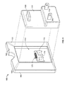
- FIG. 1 is a front isometric view of a first embodiment of a dispensing device
- FIG. 2 is a rear isometric view of a volatile material container for use with the dispensing device of FIG. 1 ;
- FIG. 3 is an exploded front isometric view of the dispensing device of FIG. 1 ;
- FIG. 4 is an exploded rear isometric view of the dispensing device of FIG. 1 ;
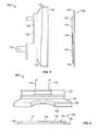
- FIG. 5 is a side elevational view of the dispensing device of FIG. 1 and the volatile material container of FIG. 2 ;
- FIG. 6 is a top plan view of the dispensing device and volatile material container of FIG. 5 ;
- FIGS. 7, 7A, and 7B are partial sectional views of the volatile material container of FIG. 2 taken generally along the lines 7-7, 7A-7A, and 7B-7B, respectively, depicting various positions of second magnetic elements;
- FIG. 8 is an exploded rear isometric view of a dispensing device similar to the one depicted in FIG. 4 , wherein a first magnetic element is provided within a rear recess of a frame of the device;
- FIGS. 9-12 are front elevational views of the dispensing device of FIG. 1 depicting several different embodiments of first magnetic elements disposed within a frame off the device;
- FIG. 13 is a front isometric view of an alternative embodiment of a dispensing device with a frame having a substantially planar front wall;
- FIG. 14 is a front isometric view of another embodiment of a dispensing device, which does not include a first magnetic element on a frame thereof;
- FIGS. 15-18 are front elevational views of different embodiments of volatile material containers similar to the one depicted in FIG. 2 , depicting various positions of second magnetic elements;
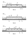
- FIGS 19-21 are partial sectional views of the volatile material container of FIGS 15-17 , respectively, wherein second magnetic elements are depicted attached to a bottom wall of the container,
- FIGS 22-24 are partial sectional views of the volatile material container of FIGS. 15-17 , respectively, wherein second magnetic elements are depicted attached to a permeable membrane of the container;
- FIG. 25 is a partial sectional view of the volatile material container of FIG. 18 , wherein second magnetic elements are depicted suspended within the container;
- FIG 26 is yet another embodiment of a dispensing device, which includes a cover plate with a bulbous protrusion;
- FIG. 27 is a still different embodiment of a dispensing device similar to the one shown in FIG 1 , further including a sensor for activation of the device.
- the dispensing device 100 includes a frame 102 having a front face 104, a rear face 106, and four sidewalls 108.
- the four sidewalls 108 are preferably equidistant in length and width and are substantially perpendicularly disposed in relation to the front and rear faces 104, 106.
- the frame 102 is generally square in cross-section, the frame 102 may be designed to comprise any number of shapes including, but not limited to, rectangular, oval, or pyramidal shapes
- the frame 102 is preferably constructed from an injection-molded plastic, but may alternatively be constructed from a variety of compositions, including glass or copolyester resins
- the front face 104 and the rear face 106 include a front recess 112 and a rear recess 114, respectively.
- electrical leads 116 are disposed within the rear recess 114, The electrical leads 116 are configured to connect to electrical prongs 118 of an electrical plate 120.
- the electrical plate 120 is attached to the rear face 106 by an adhesive, one or more fasteners, a friction fit between portions of the electrical plate 120 and the portions of the frame 102 defining the rear recess 114, or by any other mechanism known to those of skill in the art.
- the electrical plate 120 may be integral with the rear face 106 of the frame 102.
- the electrical plate 120 is generally rectangular in shape and includes a front surface 122 and a rear surface 124.
- the electrical prongs 118 extend substantially perpendicularly from the rear surface 124 of the electrical plate 120 to the front surface 122 thereof.
- the electrioal prongs 118 are adapted to be inserted into a traditional wall outlet (not shown) to provide power to the dispensing device 100. It will be apparent to one of skill in the art that the electrical prongs 118 may be modified to service varying types of outlets.
- the electrical leads 116 provided within the rear recess 114 are in electrical communication with a heating element 125.
- the heating element 125 is preferably a ceramic covered resistor. However, it is envisioned that any other type of heating element may be used in conjunction with the present embodiments.
- the heating element 125 is substantially centrally disposed within the rear recess 114, In other embodiments, the heating element 125 is off-centered from the position shown in FIG. 4 . Further, the heating element 125 may extend fully or partially a width and/or height of the rear recess 114 in other embodiments. Still further, a plurality of heating elements 125 may be provided in electrical communication with the electrical leads 116. It is also contemplated that one or more of the heating element 125 and the electrical leads 116 may be positioned within the frame 102 or fully or partially within or on the front or rear faces 104, 106 of the frame 102.
- the electrical plate 120 may include a battery housing (not shown) in lieu of the electrical prongs 118. In a further embodiment, the electrical plate 120 may include both a battery housing and the electrical prongs 118. In yet another alternative embodiment, the electrical plate 120 may include electrical prongs 118 and a rechargeable battery (not shown). In a further alternative embodiment, the electrical prongs 118 may be hingedly attached to the electrical plate 120 so that they may be folded into the dispensing device 100.
- a first magnetic element 126 is disposed within an interior of the frame 102 between the front and rear recesses 112, 114.
- the first magnetic element 126 of the present embodiment is depicted as being provided above the heating element 125 and substantially centrally disposed about a width of the frame 102.
- the first magnetic element 126 may extend fully or partially a width and/or height of the frame 102.
- the first magnetic element 126 is provided within the frame 102 in alignment with the heating clement 125.
- the first magnetic element 126 is circular shape.
- the first magnetic element 126 may also comprise any other geometric shape including, but not limited to, rectangular, spherical, oval, elliptical, or pyramidal shapes.
- the first magnetic element 126 of the present embodiment is shown within a wall comprising the frame 102 between the front and rear recesses 112, 114.
- the first magnetic element 126 may be formed within the frame 102 during the manufacturing process, provided within a bore or recess in one of the front or rear faces 104, 106 (not shown), placed between two separable portions of the frame 102 (not shown), or provided within the frame 102 in any manner known to one of skill in the art. It is also intended that the first magnetic element may be disposed on a surface of the frame 102 defining a portion of the front or rear recesses 112, 114. For example, the first magnetic element 126 depicted in FIGS.
- FIG. 8 depicts an alternative embodiment of a frame 202, wherein the first magnetic element 126 is disposed within the rear recess 114 of the frame 202.
- the front recess 112 is configured to receive a volatile material container 128.
- the front recess 112 is preferably shaped in a complementary fashion to that of the container 128 so that same may be nested within the front recess 112.
- the container 128 is presented with greater particularity.
- the container 128 contains a volatile material 130 within a blister 132, which is preferably a thermoformed structure.
- the container 128 includes a bottom wall 134 and sidewalls 136 that extend therefrom and terminate at a surrounding flange 138.
- the four sidewalls 136 are preferably the same length and width.
- a vapor permeable membrane 140 is adhered to the surrounding flange 138 and extends across the blister 132 (see FIG. 7 ).
- the permeable membrane 140 in conjunction with the bottom wall 134 and the sidewalls 136., act to contain the volatile material 130 within the sealed reservoir of the blister 132.
- An impermeable laminate 142 is releasably adhered to the container 128 over the permeable membrane 140. While the impermeable laminate 142 is in place, the volatile material 130 is prevented (or substantially prevented) from diffasing into the atmosphere.
- the volatile material, 130 may comprise an active ingredient for diffusion into the surrounding atmosphere, such as a fragrance, air freshener, odor eliminator, or insect repellant or insecticide.
- the volatile material may be a liquid, a gel, a solid, a gas, a mix of the aforementioned forms, or any other form known to those of skill in the art. It is contemplated that any type of volatile material suited for dispersal through a permeably membrane may be used with the present embodiments described herein.
- the permeable membrane 140 has a thickness of about 0.05 mm to about 0.15 mm and has a density within a range of about 0.88 to 0.95 grams/cubic centimeter.
- the permeable membrane 140 may also be formed integrally with the impermeable laminate 142 and is heat fused to the flange 138 such that the permeable membrane 140 extends across the entire blister 132.
- the permeable membrane 140 is a 5 layer co-extrusion, which includes first and second layers of a blend of low density polyethylene (LDPE) and ultra low density polyethylene (ULDPE) bonded to opposing sides of a first LDPE layer.
- LDPE low density polyethylene
- ULDPE ultra low density polyethylene
- a second LDPE layer is also bonded to the second LDPE/ULDPE layer and a polypropylene (PP) layer is bonded to the opposite side of the second LOPE layer.
- the permeable membrane 140 is preferably clear and translucent, allowing for visibility of the volatile material 130 therethrough.
- the size of the permeable membrane 140 is a key factor in the diffusion rate of the volatile material 130 therethrough. The smaller the surface area of the permeable membrane 140, the less volatile material 130 that is released, which may result in lower fragrance intensity being detected by the consumer. Other factors that may influence the diffusion rate of the volatile material include the specific composition of the volatile material, the thickness and composition of the permeable membrane, and the amount of volatile material contained within the container 128.
- the impermeable laminate 142 may include a layer of polypropylene, aluminum foil, and/or polyester.
- the impermeable laminate includes a layer of aluminum foil, a layer of polypropylene (PP) adhered to one face of the aluminum foil by a PP adhesive, and a layer of polyethylene terephthalate (PET) bonded to another face of the aluminum foil.
- the PP layer of the foil cover is in contact with the PP layer of the vapor-permeable membrane when the foil cover is sealed thereto.
- the impermeable laminate 142 has a thickness of between about 0.1 mm and about 0.2 mm.
- the polyester layer is generally suitable for printing and may be the outer surface of the impermeable laminate 142.
- the container 128 includes a second magnetic element 144.
- the second magnetic element 144 is attached to the bottom wall 134 of the blister 132.
- the second magnetic element could instead be attached to one or more of the sidewalls 136, the permeable membrane 140, or be provided unattached within the container 128 between the blister 132 and the permeable membrane 140 (see FIGS. 7A and 7B ).
- the second magnetic element 144 is formed in the shape of a square. In other embodiments, the second magnetic element 144 may be designed to comprise any number of shapes including, but not limited to, rectangular, ova, or pyramidal shapes.
- the second magnetic element 144 within the container 134 is magnetically attracted to the first magnetic element 126 in the frame 102. In this way, the container 128 is magnetically retained by the frame 102.
- the magnetic elements described herein generally refer to materials or objects that produce and/or are attracted to a magnetic field.
- the first and second magnetic elements are both permanently magnetized, such that both the first and second magnetic elements maintain their own magnetic fields indefinitely or for substantially long periods of time.
- at least one of the first and second magnetic elements is a permanent magnet and the other of the first and second magnetic elements comprises a ferroinagnetic material, such that the material may be magnetized by a magnetic field and/or attracted to materials that are magnetized
- at least one of the first and second magnetic elements is an electromagnetic material, which produces a magnetic field or takes on the properties of a femomagnetic material when an electric current passes through it.
- the electrical leads 116 may be in electrical communication with the first magnetic element 126.
- the magnetic elements may consist of combinations of permanently magnetized materials, ferromagnetic materials, and/or electromagnetic materials.
- the container will not be retained by the dispensing device 100.
- the dispensing device 100 prevents inadvertent use of containers, which may be incompatible with the device, e.g., the container may not be suited for withstanding heat from the heating element 125 or the container may include a volatile material incompatible with the environment the device is in, such as a pesticide in a bathroom. Indeed, it is also contemplated that varying refills with second magnetic elements 144 will only work with dispensing devices having compatible first magnetic elements.
- one embodiment utilizes a frame 102 having an electromagnetic first element 140 that produces a magnetic field with a strength insufficient to retain a container with a second ferromagnetic element, but that is sufficient to retain a different container with a second permanent magnetic element.
- both of the previously noted ferromagnetie and permanent second magnetic elements may also be adapted to be retained by a frame 102 having a first permanent magnetic element. It is contemplated that one of skill in the art reading the present disclosure will understand how different magnetic elements with varying magnetic field strengths may be used to preclude inadvertent container usage with the various dispensing devices disclosed herein.
- the impermeable laminate 142 is removed from the blister 132.
- a user removes the impermeable laminate 142 by grasping an end thereof and peeling it off the blister 132.
- a tab, extension, or other means for grasping may be included as an extension of the impermeable laminate 142 to aid in removal of same.
- the extension (not shown) is preferably provided at a corner of the impermeable laminate 142, but may extend from any portion thereof.
- the dispensing device 100 of the present embodiment may dispense volatile material into the atmosphere actively or passively.
- a user removes the impermeable laminate 142 from the blister 132, but does not activate the heating device. This allows the dispensing device to passively emit the volatile material 130 from the blister 132 through the permeable membrane 140 and into the atmosphere unassisted.
- the dispensing device 100 may be electrically connected to an outlet with an activation switch, sensor, or other activation means (not shown) turned to an off position to allow for passive diffusion of the volatile material 130.
- the dispensing device 100 could be rested upon a support surface (not shown), such as a desk or table, to allow the passive diffusion of the volatile material 130.
- the dispensing device 100 may also include an activation switch, sensor, or other activation means (not shown) turned to an on position to activate the heating element 125 when plugged into a wall outlet.
- an activation switch, sensor, or other activation means turned to an on position to activate the heating element 125 when plugged into a wall outlet.
- electrical energy is transferred from the wall outlet through the electrical prongs 118 and to the heating element 125.
- the heating element 125 converts the electrical energy into thermal energy. Thermal energy is conducted through a wall of the frame 102 between the heating element 125 and the container 128, and is thereafter conducted through the blister 132 and into the volatile material 130.
- the conduction of thermal energy throughout the dispensing device 100 acts to increase the volatilization of the volatile material 130 through the permeable membrane 140 and the active diffusion of the volatile material 130 into the atmosphere.
- the increased diffusion rate allows for a stronger concentration of the volatile material 130 in a given area and/or the ability to effectively disperse the volatile material 130 to a larger area.
- conduction of thermal energy through the first and/or second magnetic elements 126, 144 produces the surprising result of a further increased rate of volatilization of the volatile material 130.
- the first and second magnetic elements 126, 144 act as heat sinks to assist in spreading the thermal energy delivered by the heating element 125 to the container 128.
- FIGS. 9-12 illustrate several views of the front face 104 of alternative embodiments of the frame 102 of the dispensing device 100, wherein the depicted first magnetic element(s) may be disposed within the frame or on the front or rear 104, 106 faces thereof.
- FIG. 9 depicts the frame 102 having multiple first magnetic elements 226 instead of a single first magnetic element 126.
- the first magnetic elements 226 are depicted as flat rectangular strips of magnetic material.
- the first magnetic elements 226 may includes any geometric shape, size, or positional pattern as previously noted herein and as may be provided for in the following embodiments.
- FIG. 9 illustrate several views of the front face 104 of alternative embodiments of the frame 102 of the dispensing device 100, wherein the depicted first magnetic element(s) may be disposed within the frame or on the front or rear 104, 106 faces thereof.
- FIG. 9 depicts the frame 102 having multiple first magnetic elements 226 instead of a single first magnetic element 126.
- the first magnetic elements 226 are depicte
- FIG. 10 illustrates another embodiment of the frame 102, wherein first magnetic elements 228 are embodied in small circular portions of magnetic material positioned in a matrix formation.
- FIG. 11 illustrates a further alternative embodiment of the frame 102 that includes a single first magnetic element 230 that spans the majority of the front recess 112.
- FIG. 12 depicts another alternative embodiment of the frame 102, which includes a plurality of first magnetic elements 232 in the shape of angled rectangular strips.
- FIG. 13 illustrates a different embodiment of a dispensing device 300 similar to the dispensing device 100 except tor the following differences.
- a frame 302 is provided that does not include a recess. Rather, the front face 104 of the frame 302 comprises a substantially planar front wall 304. Similar to the previous embodiments noted herein, the first magnetic element 126 is positioned within the frame 302 or on the front or rear 104, 106 faces thereof.
- first magnetic element 126 is depicted as a circular element centered about a width of the flame 302, the first magnetic element 126 of the present embodiment may comprise any geometric shape, size, or positional pattern as previously noted herein and as may be provided for in the following embodiments.
- FIG. 14 illustrates yet another embodiment of a dispensing device 400 similar to the dispensing device 100 except for the below noted differences.
- the first magnetic element 126 is not provided.
- a heating element 425 provides heat in a similar manner as the heating element 125 with the additional functional advantage of operating as an electromagnet. When supplied with current, the heating element 425 produces a magnetic field to assist in coupling the dispensing device 400 with the second magnetic element 144 of the container 128.
- the heating element 425 is depicted as extending through the front face 104 of the frame 102 within the front recess 112.
- the heating element 425 may be attached to the frame 102 in any manner as noted herein, e.g., one or more of the heating element 425 and the electrical leads 116 may be positioned within the frame 102 or fully or partially within or on the front or rear faces 104, 106 of the frame 102. In other embodiments there may be several heating elements 425 that operate as one of several first magnetic elements. Additionally, the heating element 425 may produce a magnetic field even in the absence of electric current, or may be combined with other first magnetic elements that do not rely on electric current for their magnetic properties, Further, in other embodiments the dispensing device 300 depicted in FIG. 13 may be similarly modified.
- FIGS 15-18 illustrate alternative embodiments of the volatile material container 128, wherein the containers are similar except for the following differences Refemng to FIG. 19 , a container 528 includes a plurality of second magnetic elements 544 as opposed to the single second magnetic element 144.
- the second magnetic elements 544 are formed into rectangular magnetic strips
- FIG. 16 depicts a plurality of magnetic beads 546.
- FIG. 17 illustrates several magnetic threads 548.
- FIG. 18 provides for a plurality of magnetic flakes 550. It is anticipated that other forms of magnetic material may be similarly disposed within the container 528 as known to those of skill in the art
- FIGS 15-17 the second magnetic elements 544 546, 548 are depicted in FIGS 19-21 , respectively, as being attached to the bottom wall 134 of the blister 132.
- FIGS. 22-24 depict the second magnetic elements 544, 546, 548 of FIGS. 15-17 , respectively, attached to the permeable membrane 140 of the container 128.
- any of the second magnetic elements 544-550 could instead be attached to one or more of the sidewalls 136, the bottom wall 134, or the permeable membrane 140, be provided unattached within the container 128 between the blister 132 and the permeable membrane 140, or any combination thereof.
- the second magnetic elements 544-550 may be designed to comprise any number of shapes or sizes.
- the second magnetic elements 544-550 serve to retain the volatile material container 528 within any of the above described frames Further, in some embodiments the second magnetic elements 544-550 assist in the conduction of thermal energy from the heating element 125 to assist in the volatilization of the material 130 in the blister 132
- FIG. 26 depicts an alternative embodiment of a dispensing device 600, which includes a generally square-shaped cover plate 602
- the cover plate 602 includes a bulbous protrusion 604 having orifices 606 extending therethrough.
- a raised peripheral flange 608 extends around a rear side 610 of the cover plate 602.
- the frame 102 is releasably attached to the cover plate 602 by an interference fit between peripheral portions of the frame 102 and the raised peripheral flange 608 of the cover plate 602.
- the cover plate 602 and the frame 102 are attached by a snap fit connection, an adhesive, screws, or in any other manner known to one of skill in the art.
- Attachment of the cover plate 602 to the frame 102 defines a compartment therebetween.
- the compartment comprises the space between the front face 104 of the frame 102 and the rear side 610 of the cover plate 602.
- the volatile material container 128 is positioned in the compartment.
- the cover plate 602 is attached to the frame 102 such that the compartment defined therebetween accommodates the volatile material container 128.
- the compartment or other portions of the cover plate 602 or the frame 102 may accommodate a fan (not shown) or other similar air circulation apparatus,
- the dispensing device 700 includes a frame 702 with a sensor 704 disposed within an orifice 706. While the sensor 704 and the orifice 706 of the present embodiment are disposed within a lower corner of the front face 104 of the frame 702, the sensor 704 and the orifice 706 may be located on any portion of the front face 104. In other embodiments, the sensor 704 and the orifice 706 are provided within the rear face 106, the sidewalls 108, or within the front or rear recesses 112, 114 of the frame 702.
- the sensor 704 is preferably adapted to activate the heating element 125 in response to a sensed condition.
Landscapes
- Health & Medical Sciences (AREA)
- Veterinary Medicine (AREA)
- Composite Materials (AREA)
- Animal Behavior & Ethology (AREA)
- General Health & Medical Sciences (AREA)
- Public Health (AREA)
- Epidemiology (AREA)
- Chemical & Material Sciences (AREA)
- Life Sciences & Earth Sciences (AREA)
- Engineering & Computer Science (AREA)
- Mechanical Engineering (AREA)
- Catching Or Destruction (AREA)
- Disinfection, Sterilisation Or Deodorisation Of Air (AREA)
- Mixers With Rotating Receptacles And Mixers With Vibration Mechanisms (AREA)
- Separation Using Semi-Permeable Membranes (AREA)
Abstract
Description
- Not Applicable
- Not Applicable
- Not Applicable
- The present invention generally relates to a device for a volatile material, and more particularly, to a device having a retention structure for securing a removable cartridge with a volatile material.
- Dispensing devices are generally known. Some dispensing devices release volatiles into the atmosphere from pressurized systems using activation, mechanisms. Other prior art dispensing devices use pump mechanisms to dispense volatiles into the atmosphere. Still other dispensing devices use heating mechanisms to assist in the volatilization of a product. Further, some dispensing devices rely on porous wicks and/or ambient air to dispense volatiles into the atmosphere via evaporation.
- Many dispensing devices dispense product from refillable or replaceable product containers. Topically, product containers must be secured to the dispensing device in order to ensure proper operation. Common retention mechanisms traditionally include housing enclosures, fitted seats, slides, flanges, and the like. Additionally, a product container must be properly configured to work with the dispensing device to ensure effective operation. Some prior art systems use sensors to determine whether a product container is properly configured to work with the dispensing device. Other systems use electronic circuitry or electromagnetic locks.
- The present disclosure contemplates various means of securing a refillable or replaceable product container to a dispensing device. The disclosed embodiments allow for the proper configuration and easy retention of a product container. Further, the embodiments provide for the effective diffusion of volatiles into the atmosphere. Several of the embodiments disclosed herein further utilize convenient frames and/or other structures to allow for easy conversion from active to passive emission or vice versa.
- According to one embodiment, a volatile material dispensing system includes a frame having a front face and a rear Face. A first magnetic element is disposed on the frame. A reservoir containing a volatile material is provided. A second magnetic element is disposed on the reservoir.
- According to another embodiment, a volatile material container includes a blister having a bottom wall, a peripheral flange, and a sidewall extending therebetween. A vapor permeable membrane is attached to the peripheral flange and extends across the blister. The vapor permeable membrane in conjunction with the bottom wall and the sidewall contains a volatile material within the blister. A magnetic element is disposed within the blister.
- According to a different embodiment, a volatile material dispenser includes a frame having a front face, a rear face, and a sidewall therebetween. A recess is disposed within the rear face. A heating element is disposed within the recess of the rear face. An electrical outlet is in electrical communication with the heating element. A magnetic element is disposed on the frame.
-
FIG. 1 is a front isometric view of a first embodiment of a dispensing device; -
FIG. 2 is a rear isometric view of a volatile material container for use with the dispensing device ofFIG. 1 ; -
FIG. 3 is an exploded front isometric view of the dispensing device ofFIG. 1 ; -
FIG. 4 is an exploded rear isometric view of the dispensing device ofFIG. 1 ; -
FIG. 5 is a side elevational view of the dispensing device ofFIG. 1 and the volatile material container ofFIG. 2 ; -
FIG. 6 is a top plan view of the dispensing device and volatile material container ofFIG. 5 ; -
FIGS. 7, 7A, and 7B are partial sectional views of the volatile material container ofFIG. 2 taken generally along the lines 7-7, 7A-7A, and 7B-7B, respectively, depicting various positions of second magnetic elements; -
FIG. 8 is an exploded rear isometric view of a dispensing device similar to the one depicted inFIG. 4 , wherein a first magnetic element is provided within a rear recess of a frame of the device; -
FIGS. 9-12 are front elevational views of the dispensing device ofFIG. 1 depicting several different embodiments of first magnetic elements disposed within a frame off the device; -
FIG. 13 is a front isometric view of an alternative embodiment of a dispensing device with a frame having a substantially planar front wall; -
FIG. 14 is a front isometric view of another embodiment of a dispensing device, which does not include a first magnetic element on a frame thereof; -
FIGS. 15-18 are front elevational views of different embodiments of volatile material containers similar to the one depicted inFIG. 2 , depicting various positions of second magnetic elements; -
FIGS 19-21 are partial sectional views of the volatile material container ofFIGS 15-17 , respectively, wherein second magnetic elements are depicted attached to a bottom wall of the container, -
FIGS 22-24 are partial sectional views of the volatile material container ofFIGS. 15-17 , respectively, wherein second magnetic elements are depicted attached to a permeable membrane of the container; -
FIG. 25 is a partial sectional view of the volatile material container ofFIG. 18 , wherein second magnetic elements are depicted suspended within the container; -
FIG 26 is yet another embodiment of a dispensing device, which includes a cover plate with a bulbous protrusion; and -
FIG. 27 is a still different embodiment of a dispensing device similar to the one shown inFIG 1 , further including a sensor for activation of the device. - Other aspects and advantages of the present invention will become apparent upon consideration of the following detailed description, wherein similar structures have similar reference numerals
- As illustrated In
FIGS 1-7 , adispensing device 100 is presented Thedispensing device 100 includes aframe 102 having afront face 104, arear face 106, and foursidewalls 108. The foursidewalls 108 are preferably equidistant in length and width and are substantially perpendicularly disposed in relation to the front andrear faces frame 102 is generally square in cross-section, theframe 102 may be designed to comprise any number of shapes including, but not limited to, rectangular, oval, or pyramidal shapes Theframe 102 is preferably constructed from an injection-molded plastic, but may alternatively be constructed from a variety of compositions, including glass or copolyester resins - The
front face 104 and therear face 106 include afront recess 112 and arear recess 114, respectively. As seen inFIGS 3 and4 ,electrical leads 116 are disposed within therear recess 114, Theelectrical leads 116 are configured to connect toelectrical prongs 118 of anelectrical plate 120. Theelectrical plate 120 is attached to therear face 106 by an adhesive, one or more fasteners, a friction fit between portions of theelectrical plate 120 and the portions of theframe 102 defining therear recess 114, or by any other mechanism known to those of skill in the art. Alternatively, theelectrical plate 120 may be integral with therear face 106 of theframe 102. Theelectrical plate 120 is generally rectangular in shape and includes afront surface 122 and arear surface 124. Theelectrical prongs 118 extend substantially perpendicularly from therear surface 124 of theelectrical plate 120 to thefront surface 122 thereof. The electrioal prongs 118 are adapted to be inserted into a traditional wall outlet (not shown) to provide power to thedispensing device 100. It will be apparent to one of skill in the art that theelectrical prongs 118 may be modified to service varying types of outlets. - The electrical leads 116 provided within the
rear recess 114 are in electrical communication with aheating element 125. Theheating element 125 is preferably a ceramic covered resistor. However, it is envisioned that any other type of heating element may be used in conjunction with the present embodiments. Theheating element 125 is substantially centrally disposed within therear recess 114, In other embodiments, theheating element 125 is off-centered from the position shown inFIG. 4 . Further, theheating element 125 may extend fully or partially a width and/or height of therear recess 114 in other embodiments. Still further, a plurality ofheating elements 125 may be provided in electrical communication with the electrical leads 116. It is also contemplated that one or more of theheating element 125 and theelectrical leads 116 may be positioned within theframe 102 or fully or partially within or on the front or rear faces 104, 106 of theframe 102. - In another embodiment, the
electrical plate 120 may include a battery housing (not shown) in lieu of theelectrical prongs 118. In a further embodiment, theelectrical plate 120 may include both a battery housing and theelectrical prongs 118. In yet another alternative embodiment, theelectrical plate 120 may includeelectrical prongs 118 and a rechargeable battery (not shown). In a further alternative embodiment, theelectrical prongs 118 may be hingedly attached to theelectrical plate 120 so that they may be folded into thedispensing device 100. - With reference to
FIGS. 1 and3 , a firstmagnetic element 126 is disposed within an interior of theframe 102 between the front andrear recesses magnetic element 126 of the present embodiment is depicted as being provided above theheating element 125 and substantially centrally disposed about a width of theframe 102. However, in a different embodiment, the firstmagnetic element 126 may extend fully or partially a width and/or height of theframe 102. Further, in a different embodiment, the firstmagnetic element 126 is provided within theframe 102 in alignment with theheating clement 125. In the present embodiment, the firstmagnetic element 126 is circular shape. However, the firstmagnetic element 126 may also comprise any other geometric shape including, but not limited to, rectangular, spherical, oval, elliptical, or pyramidal shapes. - The first
magnetic element 126 of the present embodiment is shown within a wall comprising theframe 102 between the front andrear recesses magnetic element 126 may be formed within theframe 102 during the manufacturing process, provided within a bore or recess in one of the front or rear faces 104, 106 (not shown), placed between two separable portions of the frame 102 (not shown), or provided within theframe 102 in any manner known to one of skill in the art. It is also intended that the first magnetic element may be disposed on a surface of theframe 102 defining a portion of the front orrear recesses magnetic element 126 depicted inFIGS. 1 and3 may instead represent a magnetic element attached to a wall defining a portion of thefront recess 112, The firstmagnetic element 126 of this embodiment may be placed directly on the wall or within a bore or recess and held in place by an adhesive, a friction fit between portions of the firstmagnetic element 128 and portions of theframe 102, or by any other mechanism of securement known to those of skill in the art, Similarly,FIG, 8 depicts an alternative embodiment of aframe 202, wherein the firstmagnetic element 126 is disposed within therear recess 114 of theframe 202. - Turning to
FIGS. 1 and 2 , thefront recess 112 is configured to receive avolatile material container 128. Thefront recess 112 is preferably shaped in a complementary fashion to that of thecontainer 128 so that same may be nested within thefront recess 112. Now turning toFIGS. 2 and5-7 , thecontainer 128 is presented with greater particularity. Thecontainer 128 contains avolatile material 130 within ablister 132, which is preferably a thermoformed structure. Thecontainer 128 includes abottom wall 134 andsidewalls 136 that extend therefrom and terminate at a surroundingflange 138. The foursidewalls 136 are preferably the same length and width. Additionally, while thecontainer 128 is depicted as having a square shape, thecontainer 128 may be designed to comprise any number of shapes including, but not limited to, rectangular, oval, or pyramidal shapes. A vaporpermeable membrane 140 is adhered to the surroundingflange 138 and extends across the blister 132 (seeFIG. 7 ). Thepermeable membrane 140, in conjunction with thebottom wall 134 and the sidewalls 136., act to contain thevolatile material 130 within the sealed reservoir of theblister 132. Animpermeable laminate 142 is releasably adhered to thecontainer 128 over thepermeable membrane 140. While theimpermeable laminate 142 is in place, thevolatile material 130 is prevented (or substantially prevented) from diffasing into the atmosphere. - The volatile material, 130 may comprise an active ingredient for diffusion into the surrounding atmosphere, such as a fragrance, air freshener, odor eliminator, or insect repellant or insecticide. The volatile material may be a liquid, a gel, a solid, a gas, a mix of the aforementioned forms, or any other form known to those of skill in the art. It is contemplated that any type of volatile material suited for dispersal through a permeably membrane may be used with the present embodiments described herein.
- Illustratively, the
permeable membrane 140 has a thickness of about 0.05 mm to about 0.15 mm and has a density within a range of about 0.88 to 0.95 grams/cubic centimeter. Thepermeable membrane 140 may also be formed integrally with theimpermeable laminate 142 and is heat fused to theflange 138 such that thepermeable membrane 140 extends across theentire blister 132. Thepermeable membrane 140 is a 5 layer co-extrusion, which includes first and second layers of a blend of low density polyethylene (LDPE) and ultra low density polyethylene (ULDPE) bonded to opposing sides of a first LDPE layer. A second LDPE layer is also bonded to the second LDPE/ULDPE layer and a polypropylene (PP) layer is bonded to the opposite side of the second LOPE layer. Thepermeable membrane 140 is preferably clear and translucent, allowing for visibility of thevolatile material 130 therethrough. - The size of the
permeable membrane 140 is a key factor in the diffusion rate of thevolatile material 130 therethrough. The smaller the surface area of thepermeable membrane 140, the lessvolatile material 130 that is released, which may result in lower fragrance intensity being detected by the consumer. Other factors that may influence the diffusion rate of the volatile material include the specific composition of the volatile material, the thickness and composition of the permeable membrane, and the amount of volatile material contained within thecontainer 128. - The
impermeable laminate 142 may include a layer of polypropylene, aluminum foil, and/or polyester. In one embodiment, the impermeable laminate includes a layer of aluminum foil, a layer of polypropylene (PP) adhered to one face of the aluminum foil by a PP adhesive, and a layer of polyethylene terephthalate (PET) bonded to another face of the aluminum foil. The PP layer of the foil cover is in contact with the PP layer of the vapor-permeable membrane when the foil cover is sealed thereto. Illustratively, theimpermeable laminate 142 has a thickness of between about 0.1 mm and about 0.2 mm. The polyester layer is generally suitable for printing and may be the outer surface of theimpermeable laminate 142. - Turning again to
FIGS. 2 and5-7 , it may be seen that thecontainer 128 includes a secondmagnetic element 144. In the present embodiment, the secondmagnetic element 144 is attached to thebottom wall 134 of theblister 132. However, the second magnetic element could instead be attached to one or more of thesidewalls 136, thepermeable membrane 140, or be provided unattached within thecontainer 128 between theblister 132 and the permeable membrane 140 (seeFIGS. 7A and 7B ). In the present embodiment, the secondmagnetic element 144 is formed in the shape of a square. In other embodiments, the secondmagnetic element 144 may be designed to comprise any number of shapes including, but not limited to, rectangular, ova, or pyramidal shapes. When thecontainer 128 is placed within or adjacent thefront recess 112 of theframe 102, the secondmagnetic element 144 within thecontainer 134 is magnetically attracted to the firstmagnetic element 126 in theframe 102. In this way, thecontainer 128 is magnetically retained by theframe 102. - The magnetic elements described herein generally refer to materials or objects that produce and/or are attracted to a magnetic field. In a preferred embodiment, the first and second magnetic elements are both permanently magnetized, such that both the first and second magnetic elements maintain their own magnetic fields indefinitely or for substantially long periods of time. In another preferred embodiment, at least one of the first and second magnetic elements is a permanent magnet and the other of the first and second magnetic elements comprises a ferroinagnetic material, such that the material may be magnetized by a magnetic field and/or attracted to materials that are magnetized, In yet another preferred embodiment, at least one of the first and second magnetic elements is an electromagnetic material, which produces a magnetic field or takes on the properties of a femomagnetic material when an electric current passes through it. With respect to embodiments utilizing electromagnetic elements, it is contemplated that the
electrical leads 116 may be in electrical communication with the firstmagnetic element 126. Further, the magnetic elements may consist of combinations of permanently magnetized materials, ferromagnetic materials, and/or electromagnetic materials. - If a container is placed within or adjacent the
front recess 112 of theframe 102 that does not include a secondmagnetic element 144, the container will not be retained by thedispensing device 100. In this manner thedispensing device 100 prevents inadvertent use of containers, which may be incompatible with the device, e.g., the container may not be suited for withstanding heat from theheating element 125 or the container may include a volatile material incompatible with the environment the device is in, such as a pesticide in a bathroom. Indeed, it is also contemplated that varying refills with secondmagnetic elements 144 will only work with dispensing devices having compatible first magnetic elements. For example, one embodiment utilizes aframe 102 having an electromagneticfirst element 140 that produces a magnetic field with a strength insufficient to retain a container with a second ferromagnetic element, but that is sufficient to retain a different container with a second permanent magnetic element. However, both of the previously noted ferromagnetie and permanent second magnetic elements may also be adapted to be retained by aframe 102 having a first permanent magnetic element. It is contemplated that one of skill in the art reading the present disclosure will understand how different magnetic elements with varying magnetic field strengths may be used to preclude inadvertent container usage with the various dispensing devices disclosed herein. - During a non-use state of the
dispensing device 100, diffusion of thevolatile material 130 from thecontainer 128 through theimpermeable laminate 142 is prevented (or substantially prevented) by theimpermeable laminate 142. During an in use state, theimpermeable laminate 142 is removed from theblister 132. A user removes theimpermeable laminate 142 by grasping an end thereof and peeling it off theblister 132. A tab, extension, or other means for grasping (not shown) may be included as an extension of theimpermeable laminate 142 to aid in removal of same. The extension (not shown) is preferably provided at a corner of theimpermeable laminate 142, but may extend from any portion thereof. Following removal of theimpermeable laminate 142 thecontainer 128 transitions from a full or first condition toward an empty or second condition, which allows for thevolatile material 130 to be dispersed into the atmosphere. - The
dispensing device 100 of the present embodiment may dispense volatile material into the atmosphere actively or passively. In the passive state, a user removes theimpermeable laminate 142 from theblister 132, but does not activate the heating device. This allows the dispensing device to passively emit thevolatile material 130 from theblister 132 through thepermeable membrane 140 and into the atmosphere unassisted. Thedispensing device 100 may be electrically connected to an outlet with an activation switch, sensor, or other activation means (not shown) turned to an off position to allow for passive diffusion of thevolatile material 130. Alternatively, thedispensing device 100 could be rested upon a support surface (not shown), such as a desk or table, to allow the passive diffusion of thevolatile material 130. - In an active state, a user removes the
impermeable laminate 142 from theblister 132 and activates theheating element 125 by plugging theelectrical prongs 118 into a conventional wall outlet. In alternative embodiments, thedispensing device 100 may also include an activation switch, sensor, or other activation means (not shown) turned to an on position to activate theheating element 125 when plugged into a wall outlet. When in an active state, electrical energy is transferred from the wall outlet through theelectrical prongs 118 and to theheating element 125. Theheating element 125 converts the electrical energy into thermal energy. Thermal energy is conducted through a wall of theframe 102 between theheating element 125 and thecontainer 128, and is thereafter conducted through theblister 132 and into thevolatile material 130. The conduction of thermal energy throughout thedispensing device 100 acts to increase the volatilization of thevolatile material 130 through thepermeable membrane 140 and the active diffusion of thevolatile material 130 into the atmosphere. The increased diffusion rate allows for a stronger concentration of thevolatile material 130 in a given area and/or the ability to effectively disperse thevolatile material 130 to a larger area. It has also been found that conduction of thermal energy through the first and/or secondmagnetic elements volatile material 130. The first and secondmagnetic elements heating element 125 to thecontainer 128. - Various other embodiments or modifications to the previously described dispensing
device 100 are also contemplated, which may include any of the structures or alternative structures as noted hereinabove.FIGS. 9-12 illustrate several views of thefront face 104 of alternative embodiments of theframe 102 of thedispensing device 100, wherein the depicted first magnetic element(s) may be disposed within the frame or on the front or rear 104, 106 faces thereof.FIG. 9 depicts theframe 102 having multiple firstmagnetic elements 226 instead of a single firstmagnetic element 126. In the illustrated embodiment, the firstmagnetic elements 226 are depicted as flat rectangular strips of magnetic material. However, the firstmagnetic elements 226 may includes any geometric shape, size, or positional pattern as previously noted herein and as may be provided for in the following embodiments.FIG. 10 illustrates another embodiment of theframe 102, wherein firstmagnetic elements 228 are embodied in small circular portions of magnetic material positioned in a matrix formation.FIG. 11 illustrates a further alternative embodiment of theframe 102 that includes a single firstmagnetic element 230 that spans the majority of thefront recess 112.FIG. 12 depicts another alternative embodiment of theframe 102, which includes a plurality of firstmagnetic elements 232 in the shape of angled rectangular strips. -
FIG. 13 illustrates a different embodiment of adispensing device 300 similar to thedispensing device 100 except tor the following differences. In lieu of theframe 102 with thefront recess 112, aframe 302 is provided that does not include a recess. Rather, thefront face 104 of theframe 302 comprises a substantially planarfront wall 304. Similar to the previous embodiments noted herein, the firstmagnetic element 126 is positioned within theframe 302 or on the front or rear 104, 106 faces thereof. Further, while the firstmagnetic element 126 is depicted as a circular element centered about a width of theflame 302, the firstmagnetic element 126 of the present embodiment may comprise any geometric shape, size, or positional pattern as previously noted herein and as may be provided for in the following embodiments. -
FIG. 14 illustrates yet another embodiment of adispensing device 400 similar to thedispensing device 100 except for the below noted differences. In the present embodiment, the firstmagnetic element 126 is not provided. Instead, aheating element 425 provides heat in a similar manner as theheating element 125 with the additional functional advantage of operating as an electromagnet. When supplied with current, theheating element 425 produces a magnetic field to assist in coupling thedispensing device 400 with the secondmagnetic element 144 of thecontainer 128. Theheating element 425 is depicted as extending through thefront face 104 of theframe 102 within thefront recess 112. However, theheating element 425 may be attached to theframe 102 in any manner as noted herein, e.g., one or more of theheating element 425 and theelectrical leads 116 may be positioned within theframe 102 or fully or partially within or on the front or rear faces 104, 106 of theframe 102. In other embodiments there may beseveral heating elements 425 that operate as one of several first magnetic elements. Additionally, theheating element 425 may produce a magnetic field even in the absence of electric current, or may be combined with other first magnetic elements that do not rely on electric current for their magnetic properties, Further, in other embodiments thedispensing device 300 depicted inFIG. 13 may be similarly modified. -
FIGS 15-18 illustrate alternative embodiments of thevolatile material container 128, wherein the containers are similar except for the following differences Refemng toFIG. 19 , acontainer 528 includes a plurality of secondmagnetic elements 544 as opposed to the single secondmagnetic element 144. In the present embodiment, the secondmagnetic elements 544 are formed into rectangular magnetic stripsFIG. 16 depicts a plurality ofmagnetic beads 546.FIG. 17 illustrates severalmagnetic threads 548.FIG. 18 provides for a plurality ofmagnetic flakes 550. It is anticipated that other forms of magnetic material may be similarly disposed within thecontainer 528 as known to those of skill in the art - Turning to
FIGS 15-17 , the secondmagnetic elements 544 546, 548 are depicted inFIGS 19-21 , respectively, as being attached to thebottom wall 134 of theblister 132. Alternatively,FIGS. 22-24 depict the secondmagnetic elements FIGS. 15-17 , respectively, attached to thepermeable membrane 140 of thecontainer 128. It is also contemplated that any of the second magnetic elements 544-550 could instead be attached to one or more of thesidewalls 136, thebottom wall 134, or thepermeable membrane 140, be provided unattached within thecontainer 128 between theblister 132 and thepermeable membrane 140, or any combination thereof. For example, the secondmagnetic elements 550 depicted inFIG. 25 are preferably suspended within thevolatile material 130 of theblister 132 In other embodiments, the second magnetic elements 544-550 may be designed to comprise any number of shapes or sizes. Advantageously, the second magnetic elements 544-550 serve to retain thevolatile material container 528 within any of the above described frames Further, in some embodiments the second magnetic elements 544-550 assist in the conduction of thermal energy from theheating element 125 to assist in the volatilization of the material 130 in theblister 132 -
FIG. 26 depicts an alternative embodiment of adispensing device 600, which includes a generally square-shapedcover plate 602 Thecover plate 602 includes abulbous protrusion 604 havingorifices 606 extending therethrough. A raisedperipheral flange 608 extends around arear side 610 of thecover plate 602. Theframe 102 is releasably attached to thecover plate 602 by an interference fit between peripheral portions of theframe 102 and the raisedperipheral flange 608 of thecover plate 602. In alternative embodiments, thecover plate 602 and theframe 102 are attached by a snap fit connection, an adhesive, screws, or in any other manner known to one of skill in the art. - Attachment of the
cover plate 602 to theframe 102 defines a compartment therebetween. Specifically, the compartment comprises the space between thefront face 104 of theframe 102 and therear side 610 of thecover plate 602. During use, thevolatile material container 128 is positioned in the compartment. Thecover plate 602 is attached to theframe 102 such that the compartment defined therebetween accommodates thevolatile material container 128. In other embodiments, the compartment or other portions of thecover plate 602 or theframe 102 may accommodate a fan (not shown) or other similar air circulation apparatus, - Now referring to
FIG. 27 , an alternative embodiment of adispensing device 700 is provided that is similar to thedispensing device 100 except for the below noted differences. Thedispensing device 700 includes aframe 702 with asensor 704 disposed within anorifice 706. While thesensor 704 and theorifice 706 of the present embodiment are disposed within a lower corner of thefront face 104 of theframe 702, thesensor 704 and theorifice 706 may be located on any portion of thefront face 104. In other embodiments, thesensor 704 and theorifice 706 are provided within therear face 106, thesidewalls 108, or within the front orrear recesses frame 702. Different types of sensors may be used independently or in combination, including motion, light, and/or odor sensors. Other sensors may also be included as would be known to those of the skill in the art. Thesensor 704 is preferably adapted to activate theheating element 125 in response to a sensed condition. - Numerous modifications to the present invention will be apparent to those skilled in the art in view of the foregoing description. Accordingly, this description is to be construed as illustrative only and is presented for the purpose of enabling those skilled in the art to make and use the invention and to teach the best mode of carrying out same. The exclusive rights to all modifications which come within the scope of the appended claims are reserved.
The paragraphs that follow define further embodiments that form part of the present disclosure. - Paragraph 1. A volatile material dispensing system, comprising:
- a frame having a front face and a rear face;
- a first magnetic element disposed on the frame;
- a reservoir containing a volatile material; and
- a second magnetic element disposed on the reservoir.
- Paragraph 2. The volatile material dispensing system of paragraph 1, wherein the first magnetic element is disposed within a wall of the frame.
- Paragraph 3. The volatile material dispensing system of paragraph 1, wherein the first magnetic element is disposed on at least one of the front and rear faces of the frame.
-
Paragraph 4. The volatile material dispensing system of paragraph 1, wherein the first magnetic element is disposed within a recess in at least one of the front and rear faces of the frame. - Paragraph 5. The volatile material dispensing system of paragraph 1, wherein a heater is provided within the frame.
- Paragraph 6. The volatile material dispensing system of paragraph 5, wherein an electrical plate is attached to the frame.
- Paragraph 7. The volatile material dispensing system of paragraph 6, wherein the electrical plate includes electrical prongs in electrical communication with the heater.
- Paragraph 8. The volatile material dispensing system of paragraph 6, wherein the electrical plate includes a battery in electrical communication with the heater.
- Paragraph 9. The volatile material dispensing system of paragraph 1, wherein the reservoir includes a vapor permeable membrane.
- Paragraph 10. The volatile material dispensing system of paragraph 9, wherein the reservoir includes a removable impermeable laminate disposed over the vapor permeable membrane.
-
Paragraph 11. A volatile material container, comprising:- a blister having a bottom wall, a peripheral flange, and a sidewall extending therebetween;
- a vapor permeable membrane attached to the peripheral flange and extending across the blister, wherein the vapor permeable membrane in conjunction with the bottom wall and the sidewall contain a volatile material within the blister; and
- a magnetic element disposed within the blister.
- Paragraph 12. The volatile material container of
paragraph 11, wherein the magnetic element is attached to the vapor permeable membrane. - Paragraph 13. The volatile material container of
paragraph 11, wherein the magnetic element is attached to the bottom wall of the blister. - Paragraph 14. The volatile material container of
paragraph 11, wherein the magnetic element is suspended within the volatile material. - Paragraph 15. The volatile material container of
paragraph 11, wherein the magnetic element is attached to the sidewall. - Paragraph 16. The volatile material container of
paragraph 11, wherein a plurality of magnetic elements are disposed within the blister. - Paragraph 17. The volatile material container of
paragraph 11, wherein the magnetic element is adapted to be attracted to a corresponding magnetic element in a dispensing device. - Paragraph 18. A volatile material dispenser, comprising:
- a frame having a front face, a rear face, and a sidewall therebetween, wherein a recess is disposed within the rear face;
- a heating element disposed within the recess of the rear face, wherein electrical prongs are in electrical communication with the heating element; and
- a magnetic element disposed on the frame.
- Paragraph 19. The volatile material dispenser of paragraph 18, wherein the magnetic element is electromagnetic.
- Paragraph 20. The volatile material dispenser of paragraph 18, wherein the magnetic clement is adapted to attract a corresponding magnetic element in a container.
Claims (13)
- A volatile material dispensing system, comprising:a frame having a front face and a rear face;a first magnetic element disposed on the frame;a reservoir containing a volatile material; anda second magnetic element disposed on the reservoir.
- The volatile material dispensing system of claim 1, wherein the first magnetic element is disposed within a wall of the frame.
- The volatile material dispensing system of claim 1, wherein the first magnetic element is disposed on at least one of the front and rear faces of the frame,
- The volatile material dispensing system of claim 1, wherein the first magnetic element is disposed within a recess in at least one of the front and rear faces of the frame.
- The volatile material dispensing system of claim 1, wherein a heater is provided within the frame.
- The volatile material dispensing system of claim 5, wherein an electrical plate is attached to the frame.
- The volatile material dispensing system of claim 6, wherein the electrical plate includes electrical prongs in electrical communication with the heater.
- The volatile material dispensing system of claim 6, wherein the electrical plate includes a battery in electrical communication with the heater.
- The volatile material dispensing system of claim 1, wherein the reservoir includes a vapor permeable membrane.
- The volatile material dispensing system of claim 9, wherein the reservoir includes a removable impermeable laminate disposed over the vapor permeable membrane.
- A volatile material dispenser, comprising:a frame having a front face, a rear face, and a. sidewall therebetween, wherein a recess is disposed within the rear face;a heating element disposed within the recess of the rear face, wherein electrical prongs are in electrical communication with the heating element; anda magnetic element disposed on the frame.
- The volatile material dispenser of claim 11, wherein the magnetic element is electromagnetic.
- The volatile material dispenser of claim 11, wherein the magnetic element is adapted to attract a corresponding magnetic element in a container.
Applications Claiming Priority (2)
| Application Number | Priority Date | Filing Date | Title |
|---|---|---|---|
| US12/896,583 US9717814B2 (en) | 2010-10-01 | 2010-10-01 | Dispensing device |
| EP11770255.5A EP2621546B1 (en) | 2010-10-01 | 2011-09-28 | Dispensing device |
Related Parent Applications (3)
| Application Number | Title | Priority Date | Filing Date |
|---|---|---|---|
| EP11770255.5A Division EP2621546B1 (en) | 2010-10-01 | 2011-09-28 | Dispensing device |
| EP11770255.5A Division-Into EP2621546B1 (en) | 2010-10-01 | 2011-09-28 | Dispensing device |
| EP11770255.5 Division | 2011-09-28 |
Publications (2)
| Publication Number | Publication Date |
|---|---|
| EP2682133A1 true EP2682133A1 (en) | 2014-01-08 |
| EP2682133B1 EP2682133B1 (en) | 2017-03-01 |
Family
ID=44801175
Family Applications (2)
| Application Number | Title | Priority Date | Filing Date |
|---|---|---|---|
| EP11770255.5A Not-in-force EP2621546B1 (en) | 2010-10-01 | 2011-09-28 | Dispensing device |
| EP13186797.0A Not-in-force EP2682133B1 (en) | 2010-10-01 | 2011-09-28 | Dispensing device for volatile materials |
Family Applications Before (1)
| Application Number | Title | Priority Date | Filing Date |
|---|---|---|---|
| EP11770255.5A Not-in-force EP2621546B1 (en) | 2010-10-01 | 2011-09-28 | Dispensing device |
Country Status (11)
| Country | Link |
|---|---|
| US (1) | US9717814B2 (en) |
| EP (2) | EP2621546B1 (en) |
| JP (1) | JP6017428B2 (en) |
| KR (2) | KR101821443B1 (en) |
| CN (1) | CN103298492B (en) |
| AR (1) | AR083283A1 (en) |
| AU (1) | AU2011308881B2 (en) |
| BR (1) | BR112013007846A2 (en) |
| ES (2) | ES2626377T3 (en) |
| MX (1) | MX346329B (en) |
| WO (1) | WO2012044659A1 (en) |
Cited By (1)
| Publication number | Priority date | Publication date | Assignee | Title |
|---|---|---|---|---|
| US11944096B2 (en) | 2019-12-06 | 2024-04-02 | S.C. Johnson & Son, Inc. | Dispenser and method of use thereof |
Families Citing this family (15)
| Publication number | Priority date | Publication date | Assignee | Title |
|---|---|---|---|---|
| EP2429844B1 (en) * | 2009-05-12 | 2020-03-25 | The Procter and Gamble Company | Dispenser for volatile compositions |
| CA2771809A1 (en) * | 2009-09-28 | 2011-03-31 | Fmc Corporation | Ampoule for the storage and dispersion of volatile liquids |
| BR122019014181B1 (en) | 2011-07-01 | 2021-03-09 | Samsung Electronics Co., Ltd | video decoding method |
| US9278151B2 (en) | 2012-11-27 | 2016-03-08 | S.C. Johnson & Son, Inc. | Volatile material dispenser |
| WO2015056252A2 (en) * | 2013-10-18 | 2015-04-23 | Oglesby & Butler Research & Development Limited | An evaporator |
| WO2015106070A1 (en) * | 2014-01-10 | 2015-07-16 | Agilex Flavors & Fragrances, Inc. | Air freshener composition and methods thereof |
| ES2556162B1 (en) * | 2014-07-11 | 2016-11-14 | Zobele España, S.A. | Evaporator of volatile substances |
| US20190307912A1 (en) * | 2015-10-20 | 2019-10-10 | Takasago International Corporation | Fragrance delivery device, system, and method |
| EP3370782A4 (en) | 2015-11-02 | 2019-07-24 | Pura Scents, Inc. | DISTRIBUTION OF FRAGRANCE |
| US12290060B2 (en) * | 2019-10-15 | 2025-05-06 | S. C. Johnson & Son, Inc. | Insect trap device |
| JP6750079B1 (en) * | 2019-10-30 | 2020-09-02 | 株式会社アロマジョイン | Fragrance cartridge and method of attaching/detaching fragrance cartridge to/from fragrance display |
| KR102853280B1 (en) * | 2020-10-08 | 2025-09-01 | 주식회사 엘지화학 | Thermoplastic resin composition, and plated molding product produced therefrom |
| US12514946B2 (en) | 2020-11-17 | 2026-01-06 | Takasago International Corporation (Usa) | Fragrance releasing device |
| USD1024306S1 (en) * | 2022-06-20 | 2024-04-23 | Energizer Auto, Inc. | Air freshener |
| USD1023278S1 (en) * | 2022-06-20 | 2024-04-16 | Energizer Auto, Inc. | Air freshener |
Citations (4)
| Publication number | Priority date | Publication date | Assignee | Title |
|---|---|---|---|---|
| US4067692A (en) * | 1976-06-10 | 1978-01-10 | Farris Richard W | Odor control device |
| JPH1057464A (en) * | 1996-08-26 | 1998-03-03 | Chihiro Asakura | Electric aromatization device for popli |
| US7661929B1 (en) * | 2005-03-17 | 2010-02-16 | Mcvay Angela Jean | Ceiling fan scent holder and placement handle |
| EP2308340A1 (en) * | 2009-10-07 | 2011-04-13 | Errebi S.r.l. | Device for the treatment of environments |
Family Cites Families (133)
| Publication number | Priority date | Publication date | Assignee | Title |
|---|---|---|---|---|
| US2742090A (en) | 1952-07-25 | 1956-04-17 | Texaco Development Corp | Setting well casings |
| US2931880A (en) | 1958-10-13 | 1960-04-05 | Cory Corp | Electrical deodorizing device |
| US2942090A (en) | 1958-11-28 | 1960-06-21 | Charles C Diehl | Deodorizer with electrical heating element |
| GB936027A (en) | 1959-10-13 | 1963-09-04 | Amf Ltd | Improvements in or relating to the dispensing of liquids containing dissolved gas under pressure |
| FR1596401A (en) | 1968-12-26 | 1970-06-15 | ||
| US3581266A (en) | 1968-12-30 | 1971-05-25 | Lionel E Weyenberg | Housed resistor |
| US4037082A (en) | 1976-04-30 | 1977-07-19 | Murata Manufacturing Co., Ltd. | Positive temperature coefficient semiconductor heating device |
| US4629604A (en) | 1983-03-21 | 1986-12-16 | Donald Spector | Multi-aroma cartridge player |
| US4549250A (en) | 1984-10-30 | 1985-10-22 | Donald Spector | Night light assembly |
| JPS621632U (en) * | 1985-06-18 | 1987-01-08 | ||
| US4804821A (en) | 1986-06-24 | 1989-02-14 | Environmental Fragrance Technologies, Ltd. | Aroma diffuser assembly |
| US4714984A (en) | 1986-09-03 | 1987-12-22 | Donald Spector | Night light assembly |
| US4785642A (en) | 1987-01-13 | 1988-11-22 | Eric Chiao Shih | Decorative clip with perfume dispenser |
| JPS6470063A (en) * | 1987-09-11 | 1989-03-15 | Sanki Kk | Fragrance volatilizing method, and containing bin and volatilizing apparatus used therein |
| JPH0174778U (en) * | 1987-11-07 | 1989-05-22 | ||
| US4849606A (en) | 1987-12-23 | 1989-07-18 | S. C. Johnson & Son, Inc. | Tamper-resistant container utilizing a flexible seal |
| US4853517A (en) | 1988-03-28 | 1989-08-01 | John G. Bowen | Vaporizing unit |
| GB2228681A (en) | 1989-03-04 | 1990-09-05 | Secto Co Ltd | Apparatus for dispensing, in vapour form, a volatile liquid |
| US5014913A (en) | 1990-02-12 | 1991-05-14 | Reckitt & Colman Inc. | Air-freshening device |
| US5111477A (en) | 1990-05-07 | 1992-05-05 | Technical Concepts, L.P. | Fragrance diffuser |
| US5175791A (en) | 1990-05-07 | 1992-12-29 | Technical Concepts, L.P. | Fragrance diffuser having stepped power levels |
| GB9109442D0 (en) | 1991-05-01 | 1991-06-26 | Volex Group Plc | Apparatus for emitting a chemical agent |
| US5136684A (en) | 1991-10-02 | 1992-08-04 | Certified Chemicals, Inc. | Heating device for volatilization of fragrant gel |
| US5213523A (en) | 1992-10-21 | 1993-05-25 | Heaters Engineering, Inc. | Apparatus and method of making an electrical connection to a current carrying device |
| US5521357A (en) | 1992-11-17 | 1996-05-28 | Heaters Engineering, Inc. | Heating device for a volatile material with resistive film formed on a substrate and overmolded body |
| GB2275609B (en) | 1993-03-02 | 1997-04-02 | Johnson & Son Inc S C | A tamper resistant electrically heated vapour dispensing apparatus |
| JP3342095B2 (en) | 1993-05-07 | 2002-11-05 | 株式会社ミクニ | Ultrasonic spray device |
| JP2602915Y2 (en) * | 1993-08-31 | 2000-02-07 | 株式会社吉野工業所 | Air freshener container with pedestal |
| US5574821A (en) | 1993-11-24 | 1996-11-12 | Babasade; Wolfgang | Plug in volatile substance dispenser and method for dispensing volatiles |
| US5522008A (en) | 1994-03-16 | 1996-05-28 | Bernard; Costello J. | Device for heating and vaporizing a vaporizable module |
| US6141496A (en) | 1994-06-06 | 2000-10-31 | The Erie Ceramic Arts Company | Electrically heated air fresheners |
| GB9413754D0 (en) | 1994-07-07 | 1994-08-24 | Boc Group Plc | Liquid dispensing apparatus |
| US6205999B1 (en) | 1995-04-05 | 2001-03-27 | Aerogen, Inc. | Methods and apparatus for storing chemical compounds in a portable inhaler |
| US5603433A (en) | 1995-04-26 | 1997-02-18 | Rene; Albert | Anti-graffiti security device for aerosol dispenser cans |
| US5647052A (en) | 1995-04-28 | 1997-07-08 | Reckitt & Colman Inc. | Volatile substance dispenser and method of dispensing a volatile substance with dissipation indication |
| GB9512708D0 (en) | 1995-06-22 | 1995-08-23 | Reckitt & Colman Inc | Improvements in or relating to organic compounds |
| US5556192A (en) | 1995-07-18 | 1996-09-17 | Yeti Shine Co., Ltd. | Perfumer structure with an optically controlled night lamp |
| US5735460A (en) | 1995-09-05 | 1998-04-07 | United Industrial Trading Corp. | Air freshener housing cover |
| US5845847A (en) | 1996-05-14 | 1998-12-08 | S. C. Johnson & Son, Inc. | Air freshener dispenser device |
| US5788155A (en) | 1996-06-28 | 1998-08-04 | S. C. Johnson & Son, Inc. | Air freshener dispenser device with dual cartridge capacity |
| US5909845A (en) | 1996-06-28 | 1999-06-08 | S. C. Johnson & Son, Inc. | Wick-based liquid emanation system with child-resistant overcap |
| JPH1075997A (en) * | 1996-09-05 | 1998-03-24 | Sekisui Plastics Co Ltd | Fragrance generator |
| US5937140A (en) | 1996-09-23 | 1999-08-10 | S. C. Johnson & Son, Inc. | Thermal-fuse plug-through, plug-in diffuser |
| US6123935A (en) | 1997-04-14 | 2000-09-26 | S. C. Johnson & Son, Inc. | Air freshener dispenser device with disposable heat-activated cartridge |
| US5945094A (en) | 1997-04-14 | 1999-08-31 | S. C. Johnson & Son, Inc. | Disposable plug-in dispenser for use with air freshener and the like |
| US5976503A (en) | 1997-04-14 | 1999-11-02 | S. C. Johnson & Son, Inc. | Disposable plug-in air freshener with heat activated cartridge |
| US5882256A (en) | 1997-06-09 | 1999-03-16 | Shropshire; Maurice C. | Fragrance dispenser |
| US6097881A (en) | 1998-07-30 | 2000-08-01 | Dekko Heating Technologies, Inc. | Electrically heated chemical delivery system and method of manufacturing same |
| EP1304126A1 (en) | 1998-10-22 | 2003-04-23 | Reckitt Benckiser (UK) LIMITED | Vapour dispensing device |
| DE19951632A1 (en) | 1998-10-26 | 2000-05-25 | Saia Burgess Electronics Gmbh | Arrangement for monitoring container closure, especially for fuel tank, has magnet that holds reed contact in one switching state, annular component that produces the other state |
| US6378780B1 (en) | 1999-02-09 | 2002-04-30 | S. C. Johnson & Son, Inc. | Delivery system for dispensing volatiles |
| CN1153630C (en) | 1999-03-05 | 2004-06-16 | 约翰逊父子公司 | Vibrating liquid atomizer and method of operation |
| US6293474B1 (en) | 1999-03-08 | 2001-09-25 | S. C. Johnson & Son, Inc. | Delivery system for dispensing volatiles |
| US6382522B2 (en) | 1999-03-08 | 2002-05-07 | S. C. Johnson & Son, Inc. | Attachment method for piezoelectric elements |
| US6361752B1 (en) * | 1999-05-19 | 2002-03-26 | S. C. Johnson & Son, Inc. | Apparatus for volatilizing and dispensing a chemical into a room environment |
| MXPA01013091A (en) | 1999-06-16 | 2002-08-20 | Dial Corp | Method and apparatus for liquid vaporization with improved housing stability. |
| US6072165A (en) | 1999-07-01 | 2000-06-06 | Thermo-Stone Usa, Llc | Thin film metal/metal oxide thermocouple |
| GB9916755D0 (en) | 1999-07-17 | 1999-09-15 | Reckitt & Colmann Prod Ltd | Improvements in or relating to organic compositions |
| US6569387B1 (en) | 1999-08-10 | 2003-05-27 | S.C. Johnson & Son, Inc. | Dual function dispenser |
| US6302559B1 (en) | 1999-11-23 | 2001-10-16 | General Electric Company | Electroluminescent night light and air freshener unit |
| US6478440B1 (en) | 2000-03-10 | 2002-11-12 | S.C. Johnson & Son, Inc. | Night light air freshener |
| US6431400B1 (en) | 2000-03-21 | 2002-08-13 | Ultraclenz Engineering Group | Dispenser apparatus that controls the type and brand of the product dispensed therefrom |
| US7007861B2 (en) * | 2000-06-08 | 2006-03-07 | S.C. Johnson & Son, Inc. | Methods and personal protection devices for repelling insects |
| US6341732B1 (en) | 2000-06-19 | 2002-01-29 | S. C. Johnson & Son, Inc. | Method and apparatus for maintaining control of liquid flow in a vibratory atomizing device |
| US20040033171A1 (en) | 2000-07-27 | 2004-02-19 | The Procter & Gamble Company | Systems and devices for emitting volatile compositions |
| US6386462B1 (en) | 2000-07-31 | 2002-05-14 | S. C. Johnson & Son, Inc. | Method and apparatus for dispensing liquids in aerosolized form with minimum spillage |
| US6446880B1 (en) | 2000-08-02 | 2002-09-10 | S.C. Johnson & Son, Inc. | Replaceable reservoir for an atomizing apparatus |
| US6769631B2 (en) | 2000-09-08 | 2004-08-03 | Fresh Products, Inc. | Combination air freshener and hand lotion dispenser |
| US6853801B2 (en) | 2000-09-26 | 2005-02-08 | S. C. Johnson & Son, Inc. | Modular electrical device for delivery of volatile compounds |
| US6450419B1 (en) | 2000-10-27 | 2002-09-17 | S.C. Johnson & Son, Inc. | Self contained liquid atomizer assembly |
| US6482863B2 (en) | 2000-12-15 | 2002-11-19 | S. C. Johnson & Son, Inc. | Insect repellant formulation deliverable by piezoelectric device |
| DE10105277A1 (en) | 2001-02-02 | 2002-08-14 | Basf Ag | Process for the hydrogenation of liquid organic compounds |
| US6630110B2 (en) | 2001-03-14 | 2003-10-07 | Global Aromatics, Inc. | Method and apparatus for specialized candle |
| GB0107861D0 (en) | 2001-03-29 | 2001-05-23 | Reckitt Benckiser Uk Ltd | Improvements in or relating to containers |
| USD464416S1 (en) | 2001-06-25 | 2002-10-15 | S. C. Johnson & Son, Inc. | Plug-in aerosol dispenser |
| ATE324914T1 (en) | 2001-08-07 | 2006-06-15 | Johnson & Son Inc S C | ELECTRIC POLYFUNCTIONAL WALL SOCKET VAPORIZER |
| USD463737S1 (en) | 2001-09-17 | 2002-10-01 | S. C. Johnson & Son, Inc. | Aerosol dispenser |
| USD463736S1 (en) | 2001-09-17 | 2002-10-01 | S. C. Johnson & Son, Inc. | Aerosol dispenser |
| GB0123851D0 (en) | 2001-10-04 | 2001-11-28 | Pankhurst Design & Development | Dispersing fragrances |
| GB0126150D0 (en) | 2001-10-31 | 2002-01-02 | Gw Pharma Ltd | A device method and resistive element for vaporising a substance |
| TW532653U (en) | 2001-11-06 | 2003-05-11 | Yea-Yen Huang | USB powered perfume connector |
| JP2003164512A (en) * | 2001-12-03 | 2003-06-10 | Kao Corp | Transpiration container |
| US6857580B2 (en) | 2001-12-03 | 2005-02-22 | S.C. Johnson & Son, Inc. | Plug-in type liquid atomizer |
| US6793149B2 (en) | 2002-02-04 | 2004-09-21 | S. C. Johnson & Son, Inc. | Method and apparatus for evaporating multi-component liquids |
| JP3087867U (en) * | 2002-02-08 | 2002-08-23 | 株式会社ティーティーエム | Swing type spherical fragrance container |
| US6885811B2 (en) | 2002-08-16 | 2005-04-26 | The Dial Corporation | Methods and apparatus for dual-outlet vapor dispenser |
| US6714725B2 (en) | 2002-02-12 | 2004-03-30 | The Dial Corporation | Vapor-dispensing device |
| AU2003211089A1 (en) | 2002-02-18 | 2003-09-09 | The Dial Corporation | Vapor-dispensing device |
| US6789741B2 (en) | 2002-03-27 | 2004-09-14 | S. C. Johnson & Son, Inc. | Method and apparatus for atomizing liquids having minimal droplet size |
| WO2003086486A1 (en) | 2002-04-18 | 2003-10-23 | Matsushita Electric Industrial Co., Ltd. | Aroma diffuser |
| US6627857B1 (en) | 2002-05-09 | 2003-09-30 | Park Cities Capital, L.L.C. | Illuminating candle warming apparatus |
| US6843430B2 (en) | 2002-05-24 | 2005-01-18 | S. C. Johnson & Son, Inc. | Low leakage liquid atomization device |
| USD471087S1 (en) | 2002-06-19 | 2003-03-04 | S. C. Johnson & Son, Inc. | Aerosol dispenser |
| US7542664B2 (en) * | 2002-08-30 | 2009-06-02 | The Dial Corporation | Vaporizer with night light |
| US6752327B2 (en) | 2002-10-16 | 2004-06-22 | S. C. Johnson & Son, Inc. | Atomizer with tilted orifice plate and replacement reservoir for same |
| US6706988B1 (en) | 2002-11-08 | 2004-03-16 | S. C. Johnson & Son, Inc. | Switch actuating mechanism and electrically controlled device using same |
| US7009519B2 (en) | 2002-11-21 | 2006-03-07 | S.C. Johnson & Sons, Inc. | Product dispensing controlled by RFID tags |
| US6786427B2 (en) | 2002-12-19 | 2004-09-07 | S. C. Johnson & Son, Inc. | Liquid sealing arrangements for replaceable liquid reservoirs |
| US6969008B2 (en) | 2003-01-29 | 2005-11-29 | S. C. Johnson & Son, Inc. | Point of purchase fragrance sampling |
| US7452503B2 (en) * | 2003-01-29 | 2008-11-18 | Susan Hart, legal representative | Kinetic air dispenser |
| CN1820543B (en) | 2003-02-07 | 2010-11-17 | 约翰逊父子公司 | Diffuser with led nightlight |
| US7017829B2 (en) | 2003-04-14 | 2006-03-28 | S. C. Johnson & Son, Inc. | Atomizer wicking system |
| US6859615B2 (en) | 2003-05-01 | 2005-02-22 | Hometek International Ltd. | Multi-fragrance scent dispenser |
| GB2401548B (en) | 2003-05-13 | 2005-07-13 | Boots Healthcare Int Ltd | Improvements relating to vaporisers |
| US7277626B2 (en) | 2003-09-04 | 2007-10-02 | Bath & Body Works Brand Management, Inc. | Illuminated air freshener |
| US7028861B2 (en) | 2003-12-16 | 2006-04-18 | Joseph S. Kanfer | Electronically keyed dispensing systems and related methods of installation and use |
| US6996335B2 (en) | 2004-02-12 | 2006-02-07 | S.C. Johnson & Son, Inc. | Electrical evaporator with ratcheting wick adjuster |
| NL1025602C2 (en) | 2004-02-27 | 2005-08-30 | Sara Lee De Nv | Dispensing device. |
| US8664292B2 (en) * | 2004-05-27 | 2014-03-04 | Croda International Plc | Compositions and articles containing a cross-linked polymer matrix and an immobilized active liquid, as well as methods of making and using the same |
| US7252244B2 (en) | 2004-06-29 | 2007-08-07 | S.C. Johnson & Son, Inc. | Volatile dispenser with oriented fibrous emanator |
| US7607250B2 (en) | 2004-06-30 | 2009-10-27 | S.C. Johnson & Son, Inc. | Air freshener with picture frame |
| US7441360B2 (en) * | 2004-06-30 | 2008-10-28 | S.C. Johnson & Son, Inc. | Air freshener with picture frame |
| US7389943B2 (en) | 2004-06-30 | 2008-06-24 | S.C. Johnson & Son, Inc. | Electromechanical apparatus for dispensing volatile substances with single dispensing mechanism and cartridge for holding multiple receptacles |
| CN1596988A (en) * | 2004-09-18 | 2005-03-23 | 葛光明 | Art modeling perfume seat |
| US7621426B2 (en) | 2004-12-15 | 2009-11-24 | Joseph Kanfer | Electronically keyed dispensing systems and related methods utilizing near field frequency response |
| GB0427646D0 (en) | 2004-12-17 | 2005-01-19 | Reckitt Benckiser Uk Ltd | Device |
| USD534640S1 (en) | 2004-12-20 | 2007-01-02 | S.C. Johnson & Son, Inc. | Volatile actives dispenser |
| USD532093S1 (en) | 2004-12-20 | 2006-11-14 | S.C. Johnson & Son, Inc. | Volatile actives dispenser |
| ES2324045T3 (en) | 2005-04-27 | 2009-07-29 | THE PROCTER & GAMBLE COMPANY | CONTAINER FOR WET TOWELS AND SPARE CONTAINER WITH COMPATIBILITY INSURANCE AND COMPATIBILITY ACTUATOR. |
| US7607916B2 (en) | 2005-08-25 | 2009-10-27 | Ramon Almodovar | Self-extinguishing candle system |
| JP4548282B2 (en) * | 2005-09-05 | 2010-09-22 | パナソニック電工株式会社 | Shelf board structure |
| US20070058955A1 (en) * | 2005-09-13 | 2007-03-15 | The Dial Corporation | Vapor-emitting device with a solar-powered, active end of use indicator |
| CN101262893A (en) * | 2005-09-13 | 2008-09-10 | 日晷公司 | Vapor releasing device with active use-up indicator |
| US20070075159A1 (en) | 2005-10-03 | 2007-04-05 | Jeng-Hsi Lin | Air freshener |
| US20090218413A1 (en) | 2005-10-24 | 2009-09-03 | Intellectual Property Development Corporation Pty | Dispensing Devices |
| CN101405036A (en) | 2006-03-24 | 2009-04-08 | 索韦莱股份有限公司 | Adjustable volatile substance diffusion apparatus with container having membrane |
| US20070237498A1 (en) * | 2006-03-31 | 2007-10-11 | S.C. Johnson & Son, Inc. | Volatile material dispenser |
| US7651666B2 (en) | 2006-04-20 | 2010-01-26 | S.C. Johnson & Son, Inc. | Air treatment device with reservoir refill |
| US7771665B2 (en) | 2007-01-12 | 2010-08-10 | Group Dekko, Inc | Chemical delivery assembly |
| TWM320394U (en) * | 2007-04-23 | 2007-10-11 | Beauty Touch Company Ltd | Aromatic utensil structure |
| JP4532530B2 (en) | 2007-08-02 | 2010-08-25 | 株式会社健康医科学研究所 | Air conditioning equipment |
| US20090108094A1 (en) * | 2007-10-23 | 2009-04-30 | Yehuda Ivri | Synthetic jet air freshener |
| EP2067491A1 (en) * | 2007-12-04 | 2009-06-10 | Givaudan SA | USB-powered air-freshener |
-
2010
- 2010-10-01 US US12/896,583 patent/US9717814B2/en not_active Expired - Fee Related
-
2011
- 2011-09-28 KR KR1020137009117A patent/KR101821443B1/en not_active Expired - Fee Related
- 2011-09-28 KR KR1020177019372A patent/KR20170086670A/en not_active Abandoned
- 2011-09-28 JP JP2013531757A patent/JP6017428B2/en not_active Expired - Fee Related
- 2011-09-28 EP EP11770255.5A patent/EP2621546B1/en not_active Not-in-force
- 2011-09-28 ES ES13186797.0T patent/ES2626377T3/en active Active
- 2011-09-28 ES ES11770255.5T patent/ES2621382T3/en active Active
- 2011-09-28 CN CN201180056897.4A patent/CN103298492B/en not_active Expired - Fee Related
- 2011-09-28 EP EP13186797.0A patent/EP2682133B1/en not_active Not-in-force
- 2011-09-28 AU AU2011308881A patent/AU2011308881B2/en not_active Ceased
- 2011-09-28 MX MX2013003676A patent/MX346329B/en active IP Right Grant
- 2011-09-28 BR BR112013007846A patent/BR112013007846A2/en not_active IP Right Cessation
- 2011-09-28 WO PCT/US2011/053616 patent/WO2012044659A1/en not_active Ceased
- 2011-10-03 AR ARP110103652A patent/AR083283A1/en not_active Application Discontinuation
Patent Citations (4)
| Publication number | Priority date | Publication date | Assignee | Title |
|---|---|---|---|---|
| US4067692A (en) * | 1976-06-10 | 1978-01-10 | Farris Richard W | Odor control device |
| JPH1057464A (en) * | 1996-08-26 | 1998-03-03 | Chihiro Asakura | Electric aromatization device for popli |
| US7661929B1 (en) * | 2005-03-17 | 2010-02-16 | Mcvay Angela Jean | Ceiling fan scent holder and placement handle |
| EP2308340A1 (en) * | 2009-10-07 | 2011-04-13 | Errebi S.r.l. | Device for the treatment of environments |
Cited By (2)
| Publication number | Priority date | Publication date | Assignee | Title |
|---|---|---|---|---|
| US11944096B2 (en) | 2019-12-06 | 2024-04-02 | S.C. Johnson & Son, Inc. | Dispenser and method of use thereof |
| US12274262B2 (en) | 2019-12-06 | 2025-04-15 | S. C. Johnson & Son, Inc. | Dispenser and method of use thereof |
Also Published As
| Publication number | Publication date |
|---|---|
| JP2013543400A (en) | 2013-12-05 |
| AR083283A1 (en) | 2013-02-13 |
| JP6017428B2 (en) | 2016-11-02 |
| KR101821443B1 (en) | 2018-01-23 |
| US9717814B2 (en) | 2017-08-01 |
| EP2621546A1 (en) | 2013-08-07 |
| WO2012044659A1 (en) | 2012-04-05 |
| KR20140001862A (en) | 2014-01-07 |
| EP2682133B1 (en) | 2017-03-01 |
| CN103298492A (en) | 2013-09-11 |
| MX346329B (en) | 2017-03-15 |
| EP2621546B1 (en) | 2017-01-04 |
| KR20170086670A (en) | 2017-07-26 |
| US20120080537A1 (en) | 2012-04-05 |
| AU2011308881A1 (en) | 2013-04-18 |
| CN103298492B (en) | 2015-05-20 |
| ES2621382T3 (en) | 2017-07-03 |
| ES2626377T3 (en) | 2017-07-24 |
| BR112013007846A2 (en) | 2016-06-07 |
| MX2013003676A (en) | 2013-10-17 |
| AU2011308881B2 (en) | 2014-06-12 |
Similar Documents
| Publication | Publication Date | Title |
|---|---|---|
| EP2682133B1 (en) | Dispensing device for volatile materials | |
| US8090244B2 (en) | Volatile material dispenser | |
| CN101925368B (en) | Volatile material dispensing system | |
| US9205165B2 (en) | Volatile material dispensing system having an adjustable diffusion apparatus | |
| EP2858686B1 (en) | Fan-based volatile material dispensing system | |
| EP2067491A1 (en) | USB-powered air-freshener | |
| JP2007525380A (en) | Volatile materials | |
| MX2011007375A (en) | Fragrance dispenser. | |
| CN109475113A (en) | Heated type aromatic | |
| JP4308771B2 (en) | Disposable active substance release electrical device | |
| WO2017070344A2 (en) | Fragrance delivery device, system, and method | |
| JP2006527992A (en) | A device that allows the dissipation of steam | |
| US7106956B2 (en) | Electrical device for the release of active substances | |
| HK1081466B (en) | Electrical device for the release of active substances | |
| RO129067A2 (en) | Deodorizer |
Legal Events
| Date | Code | Title | Description |
|---|---|---|---|
| PUAI | Public reference made under article 153(3) epc to a published international application that has entered the european phase |
Free format text: ORIGINAL CODE: 0009012 |
|
| AC | Divisional application: reference to earlier application |
Ref document number: 2621546 Country of ref document: EP Kind code of ref document: P |
|
| AK | Designated contracting states |
Kind code of ref document: A1 Designated state(s): AL AT BE BG CH CY CZ DE DK EE ES FI FR GB GR HR HU IE IS IT LI LT LU LV MC MK MT NL NO PL PT RO RS SE SI SK SM TR |
|
| AX | Request for extension of the european patent |
Extension state: BA ME |
|
| 17P | Request for examination filed |
Effective date: 20140321 |
|
| RBV | Designated contracting states (corrected) |
Designated state(s): AL AT BE BG CH CY CZ DE DK EE ES FI FR GB GR HR HU IE IS IT LI LT LU LV MC MK MT NL NO PL PT RO RS SE SI SK SM TR |
|
| 17Q | First examination report despatched |
Effective date: 20160506 |
|
| GRAP | Despatch of communication of intention to grant a patent |
Free format text: ORIGINAL CODE: EPIDOSNIGR1 |
|
| INTG | Intention to grant announced |
Effective date: 20161014 |
|
| GRAS | Grant fee paid |
Free format text: ORIGINAL CODE: EPIDOSNIGR3 |
|
| GRAA | (expected) grant |
Free format text: ORIGINAL CODE: 0009210 |
|
| AC | Divisional application: reference to earlier application |
Ref document number: 2621546 Country of ref document: EP Kind code of ref document: P |
|
| AK | Designated contracting states |
Kind code of ref document: B1 Designated state(s): AL AT BE BG CH CY CZ DE DK EE ES FI FR GB GR HR HU IE IS IT LI LT LU LV MC MK MT NL NO PL PT RO RS SE SI SK SM TR |
|
| REG | Reference to a national code |
Ref country code: GB Ref legal event code: FG4D |
|
| REG | Reference to a national code |
Ref country code: CH Ref legal event code: EP Ref country code: AT Ref legal event code: REF Ref document number: 870532 Country of ref document: AT Kind code of ref document: T Effective date: 20170315 |
|
| REG | Reference to a national code |
Ref country code: IE Ref legal event code: FG4D |
|
| REG | Reference to a national code |
Ref country code: DE Ref legal event code: R096 Ref document number: 602011035600 Country of ref document: DE |
|
| REG | Reference to a national code |
Ref country code: NL Ref legal event code: MP Effective date: 20170301 |
|
| REG | Reference to a national code |
Ref country code: LT Ref legal event code: MG4D |
|
| REG | Reference to a national code |
Ref country code: AT Ref legal event code: MK05 Ref document number: 870532 Country of ref document: AT Kind code of ref document: T Effective date: 20170301 |
|
| REG | Reference to a national code |
Ref country code: ES Ref legal event code: FG2A Ref document number: 2626377 Country of ref document: ES Kind code of ref document: T3 Effective date: 20170724 |
|
| PG25 | Lapsed in a contracting state [announced via postgrant information from national office to epo] |
Ref country code: HR Free format text: LAPSE BECAUSE OF FAILURE TO SUBMIT A TRANSLATION OF THE DESCRIPTION OR TO PAY THE FEE WITHIN THE PRESCRIBED TIME-LIMIT Effective date: 20170301 Ref country code: FI Free format text: LAPSE BECAUSE OF FAILURE TO SUBMIT A TRANSLATION OF THE DESCRIPTION OR TO PAY THE FEE WITHIN THE PRESCRIBED TIME-LIMIT Effective date: 20170301 Ref country code: NO Free format text: LAPSE BECAUSE OF FAILURE TO SUBMIT A TRANSLATION OF THE DESCRIPTION OR TO PAY THE FEE WITHIN THE PRESCRIBED TIME-LIMIT Effective date: 20170601 Ref country code: GR Free format text: LAPSE BECAUSE OF FAILURE TO SUBMIT A TRANSLATION OF THE DESCRIPTION OR TO PAY THE FEE WITHIN THE PRESCRIBED TIME-LIMIT Effective date: 20170602 Ref country code: LT Free format text: LAPSE BECAUSE OF FAILURE TO SUBMIT A TRANSLATION OF THE DESCRIPTION OR TO PAY THE FEE WITHIN THE PRESCRIBED TIME-LIMIT Effective date: 20170301 |
|
| REG | Reference to a national code |
Ref country code: FR Ref legal event code: PLFP Year of fee payment: 7 |
|
| PG25 | Lapsed in a contracting state [announced via postgrant information from national office to epo] |
Ref country code: BG Free format text: LAPSE BECAUSE OF FAILURE TO SUBMIT A TRANSLATION OF THE DESCRIPTION OR TO PAY THE FEE WITHIN THE PRESCRIBED TIME-LIMIT Effective date: 20170601 Ref country code: RS Free format text: LAPSE BECAUSE OF FAILURE TO SUBMIT A TRANSLATION OF THE DESCRIPTION OR TO PAY THE FEE WITHIN THE PRESCRIBED TIME-LIMIT Effective date: 20170301 Ref country code: SE Free format text: LAPSE BECAUSE OF FAILURE TO SUBMIT A TRANSLATION OF THE DESCRIPTION OR TO PAY THE FEE WITHIN THE PRESCRIBED TIME-LIMIT Effective date: 20170301 Ref country code: LV Free format text: LAPSE BECAUSE OF FAILURE TO SUBMIT A TRANSLATION OF THE DESCRIPTION OR TO PAY THE FEE WITHIN THE PRESCRIBED TIME-LIMIT Effective date: 20170301 Ref country code: AT Free format text: LAPSE BECAUSE OF FAILURE TO SUBMIT A TRANSLATION OF THE DESCRIPTION OR TO PAY THE FEE WITHIN THE PRESCRIBED TIME-LIMIT Effective date: 20170301 |
|
| PG25 | Lapsed in a contracting state [announced via postgrant information from national office to epo] |
Ref country code: NL Free format text: LAPSE BECAUSE OF FAILURE TO SUBMIT A TRANSLATION OF THE DESCRIPTION OR TO PAY THE FEE WITHIN THE PRESCRIBED TIME-LIMIT Effective date: 20170301 |
|
| PG25 | Lapsed in a contracting state [announced via postgrant information from national office to epo] |
Ref country code: RO Free format text: LAPSE BECAUSE OF FAILURE TO SUBMIT A TRANSLATION OF THE DESCRIPTION OR TO PAY THE FEE WITHIN THE PRESCRIBED TIME-LIMIT Effective date: 20170301 Ref country code: CZ Free format text: LAPSE BECAUSE OF FAILURE TO SUBMIT A TRANSLATION OF THE DESCRIPTION OR TO PAY THE FEE WITHIN THE PRESCRIBED TIME-LIMIT Effective date: 20170301 Ref country code: EE Free format text: LAPSE BECAUSE OF FAILURE TO SUBMIT A TRANSLATION OF THE DESCRIPTION OR TO PAY THE FEE WITHIN THE PRESCRIBED TIME-LIMIT Effective date: 20170301 Ref country code: SK Free format text: LAPSE BECAUSE OF FAILURE TO SUBMIT A TRANSLATION OF THE DESCRIPTION OR TO PAY THE FEE WITHIN THE PRESCRIBED TIME-LIMIT Effective date: 20170301 |
|
| PGFP | Annual fee paid to national office [announced via postgrant information from national office to epo] |
Ref country code: DE Payment date: 20170821 Year of fee payment: 7 Ref country code: IT Payment date: 20170828 Year of fee payment: 7 Ref country code: GB Payment date: 20170821 Year of fee payment: 7 Ref country code: FR Payment date: 20170822 Year of fee payment: 7 |
|
| PG25 | Lapsed in a contracting state [announced via postgrant information from national office to epo] |
Ref country code: PL Free format text: LAPSE BECAUSE OF FAILURE TO SUBMIT A TRANSLATION OF THE DESCRIPTION OR TO PAY THE FEE WITHIN THE PRESCRIBED TIME-LIMIT Effective date: 20170301 Ref country code: SM Free format text: LAPSE BECAUSE OF FAILURE TO SUBMIT A TRANSLATION OF THE DESCRIPTION OR TO PAY THE FEE WITHIN THE PRESCRIBED TIME-LIMIT Effective date: 20170301 Ref country code: PT Free format text: LAPSE BECAUSE OF FAILURE TO SUBMIT A TRANSLATION OF THE DESCRIPTION OR TO PAY THE FEE WITHIN THE PRESCRIBED TIME-LIMIT Effective date: 20170703 Ref country code: IS Free format text: LAPSE BECAUSE OF FAILURE TO SUBMIT A TRANSLATION OF THE DESCRIPTION OR TO PAY THE FEE WITHIN THE PRESCRIBED TIME-LIMIT Effective date: 20170701 |
|
| REG | Reference to a national code |
Ref country code: DE Ref legal event code: R097 Ref document number: 602011035600 Country of ref document: DE |
|
| PLBE | No opposition filed within time limit |
Free format text: ORIGINAL CODE: 0009261 |
|
| STAA | Information on the status of an ep patent application or granted ep patent |
Free format text: STATUS: NO OPPOSITION FILED WITHIN TIME LIMIT |
|
| PG25 | Lapsed in a contracting state [announced via postgrant information from national office to epo] |
Ref country code: DK Free format text: LAPSE BECAUSE OF FAILURE TO SUBMIT A TRANSLATION OF THE DESCRIPTION OR TO PAY THE FEE WITHIN THE PRESCRIBED TIME-LIMIT Effective date: 20170301 |
|
| 26N | No opposition filed |
Effective date: 20171204 |
|
| PG25 | Lapsed in a contracting state [announced via postgrant information from national office to epo] |
Ref country code: SI Free format text: LAPSE BECAUSE OF FAILURE TO SUBMIT A TRANSLATION OF THE DESCRIPTION OR TO PAY THE FEE WITHIN THE PRESCRIBED TIME-LIMIT Effective date: 20170301 |
|
| PGFP | Annual fee paid to national office [announced via postgrant information from national office to epo] |
Ref country code: ES Payment date: 20171003 Year of fee payment: 7 |
|
| REG | Reference to a national code |
Ref country code: CH Ref legal event code: PL |
|
| PG25 | Lapsed in a contracting state [announced via postgrant information from national office to epo] |
Ref country code: MC Free format text: LAPSE BECAUSE OF FAILURE TO SUBMIT A TRANSLATION OF THE DESCRIPTION OR TO PAY THE FEE WITHIN THE PRESCRIBED TIME-LIMIT Effective date: 20170301 |
|
| REG | Reference to a national code |
Ref country code: IE Ref legal event code: MM4A |
|
| REG | Reference to a national code |
Ref country code: BE Ref legal event code: MM Effective date: 20170930 |
|
| PG25 | Lapsed in a contracting state [announced via postgrant information from national office to epo] |
Ref country code: LU Free format text: LAPSE BECAUSE OF NON-PAYMENT OF DUE FEES Effective date: 20170928 |
|
| PG25 | Lapsed in a contracting state [announced via postgrant information from national office to epo] |
Ref country code: LI Free format text: LAPSE BECAUSE OF NON-PAYMENT OF DUE FEES Effective date: 20170930 Ref country code: CH Free format text: LAPSE BECAUSE OF NON-PAYMENT OF DUE FEES Effective date: 20170930 Ref country code: IE Free format text: LAPSE BECAUSE OF NON-PAYMENT OF DUE FEES Effective date: 20170928 |
|
| PG25 | Lapsed in a contracting state [announced via postgrant information from national office to epo] |
Ref country code: BE Free format text: LAPSE BECAUSE OF NON-PAYMENT OF DUE FEES Effective date: 20170930 |
|
| PG25 | Lapsed in a contracting state [announced via postgrant information from national office to epo] |
Ref country code: MT Free format text: LAPSE BECAUSE OF NON-PAYMENT OF DUE FEES Effective date: 20170928 |
|
| REG | Reference to a national code |
Ref country code: DE Ref legal event code: R119 Ref document number: 602011035600 Country of ref document: DE |
|
| GBPC | Gb: european patent ceased through non-payment of renewal fee |
Effective date: 20180928 |
|
| PG25 | Lapsed in a contracting state [announced via postgrant information from national office to epo] |
Ref country code: HU Free format text: LAPSE BECAUSE OF FAILURE TO SUBMIT A TRANSLATION OF THE DESCRIPTION OR TO PAY THE FEE WITHIN THE PRESCRIBED TIME-LIMIT; INVALID AB INITIO Effective date: 20110928 |
|
| PG25 | Lapsed in a contracting state [announced via postgrant information from national office to epo] |
Ref country code: DE Free format text: LAPSE BECAUSE OF NON-PAYMENT OF DUE FEES Effective date: 20190402 Ref country code: IT Free format text: LAPSE BECAUSE OF NON-PAYMENT OF DUE FEES Effective date: 20180928 |
|
| PG25 | Lapsed in a contracting state [announced via postgrant information from national office to epo] |
Ref country code: FR Free format text: LAPSE BECAUSE OF NON-PAYMENT OF DUE FEES Effective date: 20180930 |
|
| PG25 | Lapsed in a contracting state [announced via postgrant information from national office to epo] |
Ref country code: CY Free format text: LAPSE BECAUSE OF NON-PAYMENT OF DUE FEES Effective date: 20170301 Ref country code: GB Free format text: LAPSE BECAUSE OF NON-PAYMENT OF DUE FEES Effective date: 20180928 |
|
| REG | Reference to a national code |
Ref country code: ES Ref legal event code: FD2A Effective date: 20191104 |
|
| PG25 | Lapsed in a contracting state [announced via postgrant information from national office to epo] |
Ref country code: MK Free format text: LAPSE BECAUSE OF FAILURE TO SUBMIT A TRANSLATION OF THE DESCRIPTION OR TO PAY THE FEE WITHIN THE PRESCRIBED TIME-LIMIT Effective date: 20170301 |
|
| PG25 | Lapsed in a contracting state [announced via postgrant information from national office to epo] |
Ref country code: ES Free format text: LAPSE BECAUSE OF NON-PAYMENT OF DUE FEES Effective date: 20180929 |
|
| PG25 | Lapsed in a contracting state [announced via postgrant information from national office to epo] |
Ref country code: TR Free format text: LAPSE BECAUSE OF FAILURE TO SUBMIT A TRANSLATION OF THE DESCRIPTION OR TO PAY THE FEE WITHIN THE PRESCRIBED TIME-LIMIT Effective date: 20170301 |
|
| PG25 | Lapsed in a contracting state [announced via postgrant information from national office to epo] |
Ref country code: AL Free format text: LAPSE BECAUSE OF FAILURE TO SUBMIT A TRANSLATION OF THE DESCRIPTION OR TO PAY THE FEE WITHIN THE PRESCRIBED TIME-LIMIT Effective date: 20170301 |