US7277626B2 - Illuminated air freshener - Google Patents
Illuminated air freshener Download PDFInfo
- Publication number
- US7277626B2 US7277626B2 US10/656,752 US65675203A US7277626B2 US 7277626 B2 US7277626 B2 US 7277626B2 US 65675203 A US65675203 A US 65675203A US 7277626 B2 US7277626 B2 US 7277626B2
- Authority
- US
- United States
- Prior art keywords
- container
- housing
- accordance
- light emitting
- emitting diodes
- Prior art date
- Legal status (The legal status is an assumption and is not a legal conclusion. Google has not performed a legal analysis and makes no representation as to the accuracy of the status listed.)
- Expired - Lifetime
Links
- 0 CCC1*2CCC1C2 Chemical compound CCC1*2CCC1C2 0.000 description 1
Images


Classifications
-
- A—HUMAN NECESSITIES
- A61—MEDICAL OR VETERINARY SCIENCE; HYGIENE
- A61L—METHODS OR APPARATUS FOR STERILISING MATERIALS OR OBJECTS IN GENERAL; DISINFECTION, STERILISATION OR DEODORISATION OF AIR; CHEMICAL ASPECTS OF BANDAGES, DRESSINGS, ABSORBENT PADS OR SURGICAL ARTICLES; MATERIALS FOR BANDAGES, DRESSINGS, ABSORBENT PADS OR SURGICAL ARTICLES
- A61L9/00—Disinfection, sterilisation or deodorisation of air
- A61L9/015—Disinfection, sterilisation or deodorisation of air using gaseous or vaporous substances, e.g. ozone
- A61L9/02—Disinfection, sterilisation or deodorisation of air using gaseous or vaporous substances, e.g. ozone using substances evaporated in the air by heating or combustion
- A61L9/03—Apparatus therefor
- A61L9/037—Apparatus therefor comprising a wick
Definitions
- the present invention relates generally to a device that functions as both an air freshener and a nightlight. More specifically, the present invention relates to circuitry and structure that optimally combine nightlight and air freshening components. Thus, the present invention advances upon the ability to combine air fresheners and nightlights into a single device.
- Air fresheners have existed for quite some time. Generally, an air freshener is used to emit a pleasant aroma into a room or enclosed area. Often the aroma is used to mask unpleasant odors. Alternatively, the aroma released by an air freshener may be used to create a mood or invoke a psychological response. In some instances, aromas are used for therapeutic purposes.
- an air freshener is plugged into a standard wall outlet, which provides both power and physical support.
- the wall outlet supplies power in the form of alternating current (“AC”) to the heating element, which in turn heats the fragrant compound.
- AC alternating current
- one known device utilizes scented liquid held by a bottle.
- the bottle contains a wick that is submerged in the scented liquid at one end and protrudes from the bottle at the other end.
- the wick draws up the scented liquid by means of capillary action.
- the end of the wick protrudes from the bottle is located next to a heating element so that the drawn up scented liquid is evaporated by the heat emitted from the heating element.
- the evaporated liquid disperses into the atmosphere, thereby emitting an aroma.
- Air fresheners may utilize a variety of heating elements. For example, some air fresheners utilize positive temperature coefficient (PTC) heating elements. Alternatively, a series of resistors may be used to heat the fragrant compound. It is also known to use resistors to heat a ceramic block, which in turn heats a wick saturated with a scented liquid. Using a power source (such as a standard wall outlet) in conjunction with one or more resistors has proven to be an effective way to emit an aroma.
- PTC positive temperature coefficient
- Nightlights have also existed for some time. They are often used in a room or an enclosed area. Nightlights are used to assist in navigation and vision when it is desirable to forego the use of standard lights. For example, a resident of a house who may wake during the night can navigate a living area more expeditiously by using a nightlight. In doing so, he or she may be able to perform a variety of tasks without disturbing the other residents by turning on brighter lights. Additionally, like air fresheners, nightlights may be used to create a mood or invoke a psychological response. For example, a nightlight may be utilized in a child's room to allay a child's fear of the dark.
- nightlights may be plugged into wall outlets for power and support.
- the wall outlet is used to power the lighting element of the nightlight.
- a nightlight may contain a circuit with a small incandescent bulb wired in series to a resistor and a pair of male terminals configured to be plugged into a standard 120 V, 60 Hz electrical socket. When this nightlight is plugged in, the bulb receives power from the wall outlet and illuminates.
- the present invention improves upon existing devices and includes circuitry that optimally and efficiently combines air freshener and nightlight components. Additionally, the present invention includes configurations for optimal illumination and includes structures that enhance the decorative and illuminative effects of the nightlight components.
- the present invention is a novel, optimized air freshener and nightlight. Specifically, the present invention provides an efficient circuitry design and a light configuration for optimal illumination.
- An apparatus of the present invention is preferably adapted to plug into an AC outlet, most preferably a 120 V, 60 Hz electrical outlet.
- the present invention may include a housing that holds the circuitry of the invention and is further configured to receive a container such as a bottle.
- the bottle and the housing preferably comprise a threaded male and female screw connector.
- the bottle of the present invention holds an aromatic, which is preferably a volatile scented liquid. A wick is inserted into the bottle and exposed to the atmosphere at one end while remaining submerged in the scented liquid at the other end.
- a resistor within the circuitry heats the aromatic, thereby causing the evaporation of the scented liquid into the atmosphere.
- the resistor is disposed in a heating block, such as a ceramic block.
- the resistor heats the heating block, which in turn heats the aromatic.
- the aromatic may be drawn up to the heating block via the capillary action of a wick.
- light emitting diodes (“LEDs”) within the circuitry illuminate.
- the bottle is clear or translucent, so as to enhance the nightlight functionality.
- the LEDs also illuminate a decorative cover that partially surrounds the housing.
- the decorative cover adds to the aesthetic effect of the invention, especially in conjunction with the LEDs.
- the cover may also evoke a particular mood or psychological effect.
- the cover is decorated in a holiday motif.
- the cover may take on a particular shape.
- the decorative cover may be made in the shape of a flower to further add to the aesthetic effect of the device.
- the LEDs can also be used in conjunction with fiber optic cables.
- Fiber optic cables are thin strands of glass used to transmit light. When a light is applied to one end of a fiber optic cable, the whole cable is illuminated.
- the LEDs are used to illuminate fiber optic cables enhancing the nightlight functionality of the device and adding to the decorative effect of the device.
- the AC input (from the wall outlet) is rectified into direct current (“DC”).
- DC direct current
- the rectified current passes through a circuit which includes four LEDs and a resistor, all of which are wired in series.
- the AC input is not rectified. Rather, a shunt diode is wired in parallel to the LEDs (biased in the reverse direction) and in series with a resistor. In this configuration, the shunt diode allows for continuous current flow through the resistor. In this embodiment, current flows through the LEDs during half of the AC cycle and through the shunt diode during the other half of the AC cycle.
- the resistor serves two functions. First, it provides heat to the aromatic.
- the resistor disposed in a heating block, may provide heat to a wick saturated with scented liquid which evaporates and is released into the atmosphere.
- the second function of the resistor is to regulate the current that passes through the LEDs. If too much current passes through the LEDs, the LEDs may malfunction or burn-out. If too little current passes through the LEDs they will not illuminate properly, thereby degrading the utility of the device.
- the resistor is a critical element of the present invention.
- more than one resistor may be used.
- a plurality of resistors may be used to more evenly heat the aromatic.
- the resistors still serve two purposes (i.e., to heat the oil and to regulate the current that passes through the LEDs).
- FIG. 1 is a perspective view showing the housing of the device and a container which holds the aromatic in accordance with the one embodiment of the present invention
- FIG. 2 is a perspective view showing the top portion of the housing in accordance with the one embodiment of the present invention
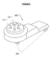
- FIG. 3 is a perspective view showing the bottom portion of the housing in accordance with one embodiment of the present invention.
- FIG. 4 is a perspective view showing the circuitry in accordance with one embodiment of the present invention.
- FIG. 5 is a side view showing a bottle which holds an aromatic and showing a wick which is partially submerged in the scented liquid in accordance with one embodiment of the present invention
- FIG. 6 depicts a decorative cover that is illuminated by the LEDs in accordance with one embodiment of the present invention
- FIG. 7 is an electrical schematic of the circuit according to one embodiment of the present invention.
- FIG. 8 is an electrical schematic of an alternative circuit according to an alternative embodiment of the present invention.
- FIG. 9 is an electrical schematic of another alternative circuit according to another alternative embodiment of the present invention.
- FIG. 10 is an electrical schematic of yet another alternative circuit according to yet another alternative embodiment of the present invention.
- the present invention is a combined air freshener/nightlight apparatus, wherein the components designated for the nightlight operate symbiotically with the components designated for the air freshener.
- the result is a unique and novel design which excels in both arts.
- an appropriate housing may be utilized for containing all of the necessary circuitry and for providing structural support.
- housing 102 of air freshener 100 in FIG. 1 A perspective view of such a housing is depicted as housing 102 of air freshener 100 in FIG. 1 .
- Housing 102 comprises cylindrical portion 104 and plug portion 106 .
- Male electrical connectors 108 protrude from inside housing 102 for plugging into an AC outlet.
- the upper portion of housing 102 comprises dome 110 which includes vents 112 .
- Vents 112 help dissipate the scented liquid. Specifically, vents 112 allow an upward convection current to flow through housing 102 , which efficiently dissipates the volatized scented oil. Further, vents 112 also allow light emitted by the LEDs to escape from housing 102 .
- a container such as bottle 114 contains an aromatic, such as a scented liquid, which is to be vaporized by air freshener 100 and can be screwed into housing 102 .
- the screw connection between bottle 114 and housing 102 may be reverse-threaded to prevent other improper bottles from being used with air freshener 100 .
- Wick 116 extends vertically from the bottom of bottle 114 and protrudes from the top of bottle 114 (not shown in FIG. 1 ).
- a pin (not pictured) may be inserted through wick 116 to secure wick 116 in place. This prevents the removal of wick 116 from bottle 114 so that the contents of bottle 114 are not spilled or tampered with.
- the housing encloses the circuitry of the apparatus.
- the housing can be comprised of two separate pieces which are snapped or glued together to hold the circuitry and to provide structural support.
- FIG. 2 is a perspective view of the top piece of such a housing.
- Top piece 202 includes dome 110 and vents 112 . Also included are snaps 204 which enable top piece 202 to be attached to the bottom half of the housing.
- top piece 202 contains the structure to allow the dispersion of fragrance and light into the atmosphere.
- Top piece 202 also provides structural support (not pictured) for male electrical connectors 108 which plug into a standard wall outlet.
- FIG. 3 is a perspective view of the bottom half of the housing.
- Bottom piece 302 holds the circuitry of the present invention.
- Bottom piece 302 also provides structure for holding the bottle and wick.
- bottom piece 302 includes a screw connection (not pictured) and wick hole 304 .
- Wick 116 protrudes through wick hole 304 so as to be heated by the circuitry of the present invention.
- Bottle 114 screws into the screw connection of bottom piece 302 .
- Bottom piece 302 also contains structure, openings 306 , to allow male electrical connectors 108 to protrude from the housing.
- Bottom piece 302 also contains structure, supports 308 , to hold the circuitry of the present invention.
- bottom piece 302 also includes snap holes 310 which receive snaps 204 .
- FIG. 4 is a perspective view of one embodiment of the circuitry.
- the circuitry of the present invention connects to male connectors 108 .
- circuit board 402 connects four diodes 404 to male connectors 108 and four light emitting diodes, LEDs 406 (only two LEDs 406 are pictured).
- LEDs 406 can be connected to fiber optic cables 408 .
- one LED 406 is connected to fiber optic cables 408 .
- a resistor (not pictured, but shown later as resistor 706 ), contained within a heating block such as ceramic block 410 is also connected to circuit board 402 , as is thermal fuse 412 .
- the circuitry is preferably enclosed by housing 102 .
- the circuitry operates to provide power to the resistor.
- the resistor heats ceramic block 410 , which in turn holds and heats wick 116 .
- ceramic block 410 contains a hole, ceramic hole 414 .
- the resistor When the resistor is powered by the circuitry, the resistor emits heat. Some of this heat is transferred to ceramic block 410 , and in turn, to wick 116 . Scented liquid contained within bottle 114 diffuses into the protruding end of wick 116 via capillary action. This scented liquid is heated by the resistor (through ceramic block 410 ) and dispersed into the surrounding environment. In this manner, the device emits an aroma.
- the resistor regulates the current that passes through LEDs 406 .
- LEDs illuminate when current passes through them.
- the strength of the illumination positively relates to the amount of current.
- too much current can cause the LEDs to malfunction, break-down or burn-out.
- a resistor is necessary to regulate the current that passes through LEDs 406 .
- the present invention optimally uses one resistor to regulate the current through LEDs 406 and to properly heat wick 116 .
- the resistor must be composed of materials that predictably inhibit the flow of current.
- the resistor may comprise a non-conducting rod coated with tin-oxide.
- the resistor may be coated with nickel-chromium.
- thermal fuse 412 The purpose of thermal fuse 412 is to open the circuit before the melting point of the housing is reached. Specifically, as is well known in the art, thermal fuse 412 breaks down and acts as an open circuit if the temperature exceeds a predetermined threshold. For example, in one embodiment, thermal fuse 412 has a threshold temperature of 325 degrees Fahrenheit. Alternatively, in place of thermal fuse 412 , an electrical fuse may be used which is designed to prevent an overload of current from passing through the circuitry of the present invention.
- circuitry depicted in FIG. 4 utilizes circuit board 402 , though the components of the circuitry can be wired together without a circuit board (i.e., with point-to-point connections). Further, this embodiment uses one resistor and four LEDs 406 , however any number of resistors or LEDs 406 may be used in the circuitry of the present invention. Specifics of exemplary circuit designs are depicted in FIGS. 7-10 and are discussed further infra.
- FIG. 5 A closer, more detailed view of bottle 114 is illustrated in FIG. 5 .
- wick 116 can be seen protruding from neck 502 of container 504 .
- the other end of wick 116 is submerged in scented liquid held by bottle 114 .
- Wick 116 absorbs the scented liquid through capillary action and allows the scented liquid to evaporate into the surroundings at the distal end of wick 116 .
- Pin 506 prevents wick 116 from being pulled out from bottle 114 .
- neck 502 is threaded to facilitate the coupling of bottle 114 to housing 102 .
- neck 502 is reverse-threaded.
- the present invention functions equally effectively with standard threading.
- container 504 is preferably clear or translucent. As discussed in greater detail infra, container 504 is clear or translucent so as to be illuminated by LEDs 406 .
- FIG. 6 is a perspective view of decorative cover 600 .
- Decorative cover 600 includes decorative shield 602 and cylinder 604 .
- Cylinder 604 may be attached or glued to housing 102 .
- cylinder 604 may attach around dome 110 of housing 102 .
- Decorative shield 602 is preferably clear or translucent so as to allow the LEDs to emit light through the shield.
- Further decorative shield 602 may include a decorative design to further the aesthetic qualities of the present invention.
- decorative shield 602 includes a holiday motif.
- decorative cover 600 and decorative shield 602 may take on various shapes and designs as desired.
- the decorative shield can be flower-shaped to further the aesthetic effect of air freshener 100 .
- the decorative shield may depict flowers where the depiction is illuminated by LEDs 406 .
- FIGS. 7-10 are electric schematics of the circuitry of the present invention. Each schematic illustrates an alternative embodiment of the present invention. However, such embodiments are merely exemplary and are not meant to limit the present invention.
- FIG. 7 is a schematic circuit diagram more specifically illustrating one of the circuit designs.
- circuit 700 is designed to receive power from AC source 702 .
- the alternating current from AC source 702 is rectified with full-wave bridge rectifier 704 .
- Full-wave bridge rectifier 704 is comprised of four diodes 404 .
- Full-wave bridge rectifier 704 is designed to convert the alternating current to direct current (“DC”).
- the resulting direct current passes through thermal fuse 412 , four LEDs 406 , and resistor 706 and back to bridge rectifier 704 to complete the circuit.
- Resistor 706 is preferably disposed in ceramic block 410 .
- Resistor 706 preferably has a resistance of approximately 7500 ohms. Such a resistance optimally heats the aromatic while providing optimal current to LEDs 406 .
- Resistor 706 may comprise various materials such as tin-oxide or nickel-chromium. The material with which resistor 706 is comprised does not substantially change the present invention so long as resistor 706 is small enough to be disposed in ceramic block 410 and so long as resistor 706 has the necessary resistance to optimally heat the aromatic while providing optimal current to LEDs 406 .
- Full-wave bridge rectifier 704 ensures that LEDs 406 and resistor 706 are powered during the full AC cycle.
- Resistor 706 provides the four LEDs 406 with optimal current such that the LEDs are illuminated but do not break down. Further, resistor 706 produces enough heat to heat wick 116 which holds the scented liquid motivating its release into the atmosphere. Therefore, circuit 700 is optimally designed for air freshener and nightlight functionality.
- FIG. 8 is an electrical schematic of an alternative circuit, circuit 800 , according to the present invention.
- circuit 800 is designed to receive alternating current (AC) from AC source 702 .
- full-wave bridge rectifier 704 converts the alternating current to direct current.
- the resulting direct current passes through thermal fuse 412 , resistor 706 and four LEDs 406 .
- the four LEDs 406 are arranged as two sets of parallel LED pairs connected in series.
- circuit 900 utilizes shunt diode 902 .
- circuit 900 contains four LEDs 406 connected in series with each other, and also utilizes resistor 706 and thermal fuse 412 .
- circuit 900 contains shunt diode 902 wired in parallel to the LEDs (biased in the reverse direction) and in series with resistor 706 .
- shunt diode 902 allows for continuous current flow through resistor 706 . Specifically, current flows through LEDs 406 during half of the AC cycle and through shunt diode 902 during the other half of the AC cycle.
- LEDs 406 only light during one half-cycle of the full AC cycle. However, the frequency with which LEDs 406 switch on and off is fast enough that the switching is not detected by the human eye. Therefore, it is perceived that LEDs 406 are always emitting light.
- circuit board 402 a two-layer printed circuit board, circuit board 402 , is utilized as part of circuit 1000 .
- the design in FIG. 10 incorporates full-wave bridge rectifier 704 , but unlike the previous examples, circuit 1000 employs only two LEDs 406 . Further, circuit 1000 utilizes electrical fuse 1002 in place of thermal fuse 412 . Electrical fuse 1002 is designed to prevent an overload of current from passing through the circuit.
- circuit 1000 is similar to that of circuit 700 (see FIG. 7 ). The differences include: 1) the positions of thermal fuse 412 , LEDs 406 , and resistor 706 relative to each other within the circuit; 2) the number of LEDs 406 ; 3) the use of electrical fuse 1002 in place of thermal fuse 412 ; and 4) the use of circuit board 402 to connect a portion of the circuitry. Specifically, all of the connections of full-wave bridge rectifier 704 and the connections between LEDs 406 are made via circuit board 402 .
Abstract
Description
Claims (54)
Priority Applications (2)
| Application Number | Priority Date | Filing Date | Title |
|---|---|---|---|
| US10/656,752 US7277626B2 (en) | 2003-09-04 | 2003-09-04 | Illuminated air freshener |
| US11/906,418 US8301019B2 (en) | 2003-09-04 | 2007-10-02 | Fragrance emanation system |
Applications Claiming Priority (1)
| Application Number | Priority Date | Filing Date | Title |
|---|---|---|---|
| US10/656,752 US7277626B2 (en) | 2003-09-04 | 2003-09-04 | Illuminated air freshener |
Related Child Applications (1)
| Application Number | Title | Priority Date | Filing Date |
|---|---|---|---|
| US11/906,418 Continuation-In-Part US8301019B2 (en) | 2003-09-04 | 2007-10-02 | Fragrance emanation system |
Publications (2)
| Publication Number | Publication Date |
|---|---|
| US20050053368A1 US20050053368A1 (en) | 2005-03-10 |
| US7277626B2 true US7277626B2 (en) | 2007-10-02 |
Family
ID=34226421
Family Applications (1)
| Application Number | Title | Priority Date | Filing Date |
|---|---|---|---|
| US10/656,752 Expired - Lifetime US7277626B2 (en) | 2003-09-04 | 2003-09-04 | Illuminated air freshener |
Country Status (1)
| Country | Link |
|---|---|
| US (1) | US7277626B2 (en) |
Cited By (22)
| Publication number | Priority date | Publication date | Assignee | Title |
|---|---|---|---|---|
| US20070237498A1 (en) * | 2006-03-31 | 2007-10-11 | S.C. Johnson & Son, Inc. | Volatile material dispenser |
| US20080253755A1 (en) * | 2003-09-04 | 2008-10-16 | Stephen Smith | Fragrance emanation system |
| US20090134239A1 (en) * | 2007-11-26 | 2009-05-28 | Hermann Neumann | Volatile material dispensing system |
| US20100086448A1 (en) * | 2008-10-07 | 2010-04-08 | Access Business Group International Llc | Air freshener powered vase |
| US20100178042A1 (en) * | 2009-01-09 | 2010-07-15 | Hermann Neumann | Fragrance dispenser |
| USD639923S1 (en) | 2010-04-15 | 2011-06-14 | S.C. Johnson & Son, Inc. | Dispensing device |
| USD659818S1 (en) | 2011-04-28 | 2012-05-15 | S.C. Johnson & Son, Inc. | Dispenser |
| USD661790S1 (en) | 2011-07-25 | 2012-06-12 | Majerowski Amelia H | Cover for a dispenser |
| US8320751B2 (en) | 2007-12-20 | 2012-11-27 | S.C. Johnson & Son, Inc. | Volatile material diffuser and method of preventing undesirable mixing of volatile materials |
| US20140028210A1 (en) * | 2012-05-07 | 2014-01-30 | Lighting Science Group Corporation | Wall-mountable luminaire and associated systems and methods |
| US8772675B2 (en) | 2011-06-15 | 2014-07-08 | Scentsy, Inc. | Electrical lighting and heating modules, assemblies and scent warmers comprising such modules, and related methods |
| US8878102B2 (en) | 2011-06-15 | 2014-11-04 | Scentsy, Inc. | Base structures, scent warmers including such base structures, and related methods |
| US9211355B2 (en) | 2010-07-27 | 2015-12-15 | Scentsy, Inc. | Scent warmers having non-incandescent heating and light-emitting devices and related methods |
| US20160213801A1 (en) * | 2015-01-22 | 2016-07-28 | Rimports (Usa) Llc | Electrical plug in fragrance dispenser having a removable decorative sheath |
| USD788899S1 (en) | 2015-08-17 | 2017-06-06 | Bath & Body Works Brand Management, Inc. | Fragrance diffuser bulb |
| USD790051S1 (en) | 2015-08-17 | 2017-06-20 | Bath & Body Works Brand Management, Inc. | Fragrance diffuser bulb |
| US9717814B2 (en) | 2010-10-01 | 2017-08-01 | S. C. Johnson & Son, Inc. | Dispensing device |
| US9801968B2 (en) | 2015-03-16 | 2017-10-31 | Cherie Graves | Lighted air freshener assembly |
| US20210228760A1 (en) * | 2017-01-31 | 2021-07-29 | Rimports Llc | Fragrance dispenser with fragrance conservation features |
| USD940291S1 (en) | 2019-07-17 | 2022-01-04 | Bath & Body Works Brand Management, Inc. | Electric fragrance diffuser |
| USD951420S1 (en) | 2019-07-11 | 2022-05-10 | Bath & Body Works Brand Management, Inc. | Home fragrance dispenser |
| USD969290S1 (en) | 2019-10-18 | 2022-11-08 | Bath & Body Works Brand Management, Inc. | Home fragrance dispenser |
Families Citing this family (18)
| Publication number | Priority date | Publication date | Assignee | Title |
|---|---|---|---|---|
| US6533215B2 (en) * | 2000-06-12 | 2003-03-18 | Thomas M. Crain | Fence spool apparatus |
| EP1541178B1 (en) * | 2002-05-06 | 2006-06-28 | Zobele Espana, S.A. | Device for evaporating active substances, comprising a built-in light |
| EP1512312A4 (en) | 2002-05-13 | 2006-11-22 | Johnson & Son Inc S C | Coordinated emission of fragrance, light, and sound |
| US20060163376A1 (en) * | 2002-10-08 | 2006-07-27 | Lakatos Kara L | Breakable wick for use in a dispenser for a volatile liquid |
| EP1608584A4 (en) | 2003-02-07 | 2006-11-02 | Johnson & Son Inc S C | Diffuser with light emitting diode nightlight |
| US7540473B2 (en) * | 2003-03-21 | 2009-06-02 | S.C. Johnson & Son, Inc. | Dispensing system for a volatile liquid |
| US7824627B2 (en) | 2004-02-03 | 2010-11-02 | S.C. Johnson & Son, Inc. | Active material and light emitting device |
| TW200704283A (en) * | 2005-05-27 | 2007-01-16 | Lamina Ceramics Inc | Solid state LED bridge rectifier light engine |
| US20080006009A1 (en) * | 2006-07-05 | 2008-01-10 | Oreck Holdings, Llc | Air cleaner nightlight |
| US7863825B2 (en) * | 2007-01-30 | 2011-01-04 | Addtek Corp. | LED driver circuit for providing desired luminance with constant current |
| US7740395B2 (en) * | 2007-05-31 | 2010-06-22 | The Procter & Gamble Company | Illuminated air treatment device |
| US7840123B2 (en) * | 2007-06-21 | 2010-11-23 | S.C. Johnson & Son, Inc. | Diffusion device |
| WO2009058868A1 (en) * | 2007-10-29 | 2009-05-07 | S.C. Johnson & Son, Inc. | Illumination devices with volatile active emissions |
| US20090289047A1 (en) * | 2008-05-23 | 2009-11-26 | Hisao Mingjen | Night light assembly |
| US20120171631A1 (en) * | 2011-01-05 | 2012-07-05 | Sherman Patterson | Cologne and Perfume Candle System |
| US10189038B2 (en) | 2013-12-20 | 2019-01-29 | Toaster Labs, Inc. | Inductively heatable fluid reservoir for various fluid types |
| US10433372B2 (en) * | 2013-12-20 | 2019-10-01 | Toaster Labs, Inc. | Portable fluid warming device |
| RU2019121605A (en) * | 2016-12-28 | 2021-01-29 | Цобеле Холдинг Спа | DEVICE FOR EVAPORATING VOLATILE SUBSTANCES CONTAINING A TAMPON AND A HEAT-REFLECTIVE ELEMENT |
Citations (10)
| Publication number | Priority date | Publication date | Assignee | Title |
|---|---|---|---|---|
| US3373341A (en) * | 1964-05-18 | 1968-03-12 | Bendix Corp | Electrical network for preventing excessive load current |
| US3386005A (en) * | 1965-08-06 | 1968-05-28 | Amp Inc | High-speed self-restoring solid state overcurrent protection circuit |
| US4968487A (en) * | 1986-09-02 | 1990-11-06 | Fumakilla Limited | Heat fumigation apparatus |
| US5175791A (en) * | 1990-05-07 | 1992-12-29 | Technical Concepts, L.P. | Fragrance diffuser having stepped power levels |
| US5274215A (en) * | 1992-11-02 | 1993-12-28 | Jackson Emily R | Portable electric food warming apparatus having a removable tray insert |
| US5716119A (en) * | 1996-08-15 | 1998-02-10 | Patel; Vipesh | Roller blade lighting system |
| US6044202A (en) * | 1999-03-25 | 2000-03-28 | Circulair, Inc. | Heated deodorizing device for dispersing a fragrance |
| US6236807B1 (en) * | 2000-01-07 | 2001-05-22 | Bath & Body Works, Inc. | Wick-based liquid emanation system with child-resistant and miniaturization features |
| US6278840B1 (en) * | 1997-06-24 | 2001-08-21 | Dbk Espana, S.A. | Evaporator device of volatile products with variable evaporation intensity |
| US6627857B1 (en) * | 2002-05-09 | 2003-09-30 | Park Cities Capital, L.L.C. | Illuminating candle warming apparatus |
-
2003
- 2003-09-04 US US10/656,752 patent/US7277626B2/en not_active Expired - Lifetime
Patent Citations (10)
| Publication number | Priority date | Publication date | Assignee | Title |
|---|---|---|---|---|
| US3373341A (en) * | 1964-05-18 | 1968-03-12 | Bendix Corp | Electrical network for preventing excessive load current |
| US3386005A (en) * | 1965-08-06 | 1968-05-28 | Amp Inc | High-speed self-restoring solid state overcurrent protection circuit |
| US4968487A (en) * | 1986-09-02 | 1990-11-06 | Fumakilla Limited | Heat fumigation apparatus |
| US5175791A (en) * | 1990-05-07 | 1992-12-29 | Technical Concepts, L.P. | Fragrance diffuser having stepped power levels |
| US5274215A (en) * | 1992-11-02 | 1993-12-28 | Jackson Emily R | Portable electric food warming apparatus having a removable tray insert |
| US5716119A (en) * | 1996-08-15 | 1998-02-10 | Patel; Vipesh | Roller blade lighting system |
| US6278840B1 (en) * | 1997-06-24 | 2001-08-21 | Dbk Espana, S.A. | Evaporator device of volatile products with variable evaporation intensity |
| US6044202A (en) * | 1999-03-25 | 2000-03-28 | Circulair, Inc. | Heated deodorizing device for dispersing a fragrance |
| US6236807B1 (en) * | 2000-01-07 | 2001-05-22 | Bath & Body Works, Inc. | Wick-based liquid emanation system with child-resistant and miniaturization features |
| US6627857B1 (en) * | 2002-05-09 | 2003-09-30 | Park Cities Capital, L.L.C. | Illuminating candle warming apparatus |
Cited By (36)
| Publication number | Priority date | Publication date | Assignee | Title |
|---|---|---|---|---|
| US20080253755A1 (en) * | 2003-09-04 | 2008-10-16 | Stephen Smith | Fragrance emanation system |
| US8301019B2 (en) * | 2003-09-04 | 2012-10-30 | Bath & Body Works Brand Management, Inc. | Fragrance emanation system |
| US20070237498A1 (en) * | 2006-03-31 | 2007-10-11 | S.C. Johnson & Son, Inc. | Volatile material dispenser |
| US8879898B2 (en) | 2007-11-26 | 2014-11-04 | S.C. Johnson & Son, Inc. | Volatile material dispensing system |
| US20090134239A1 (en) * | 2007-11-26 | 2009-05-28 | Hermann Neumann | Volatile material dispensing system |
| US8320751B2 (en) | 2007-12-20 | 2012-11-27 | S.C. Johnson & Son, Inc. | Volatile material diffuser and method of preventing undesirable mixing of volatile materials |
| US20100086448A1 (en) * | 2008-10-07 | 2010-04-08 | Access Business Group International Llc | Air freshener powered vase |
| US8137629B2 (en) | 2008-10-07 | 2012-03-20 | Access Business Group International Llc | Air freshener powered vase |
| US20100178042A1 (en) * | 2009-01-09 | 2010-07-15 | Hermann Neumann | Fragrance dispenser |
| US9453652B2 (en) | 2009-01-09 | 2016-09-27 | S. C. Johnson & Son, Inc. | Fragrance dispenser |
| US8891947B2 (en) | 2009-01-09 | 2014-11-18 | S.C. Johnson & Son, Inc. | Fragrance dispenser |
| USD639923S1 (en) | 2010-04-15 | 2011-06-14 | S.C. Johnson & Son, Inc. | Dispensing device |
| US9211355B2 (en) | 2010-07-27 | 2015-12-15 | Scentsy, Inc. | Scent warmers having non-incandescent heating and light-emitting devices and related methods |
| US9717814B2 (en) | 2010-10-01 | 2017-08-01 | S. C. Johnson & Son, Inc. | Dispensing device |
| USD659818S1 (en) | 2011-04-28 | 2012-05-15 | S.C. Johnson & Son, Inc. | Dispenser |
| US8772675B2 (en) | 2011-06-15 | 2014-07-08 | Scentsy, Inc. | Electrical lighting and heating modules, assemblies and scent warmers comprising such modules, and related methods |
| US8878102B2 (en) | 2011-06-15 | 2014-11-04 | Scentsy, Inc. | Base structures, scent warmers including such base structures, and related methods |
| US9775925B2 (en) | 2011-06-15 | 2017-10-03 | Scentsy, Inc. | Scent warmers and related methods |
| US9775926B2 (en) | 2011-06-15 | 2017-10-03 | Scentsy, Inc. | Scent warmers including lighting and heating modules and related methods |
| US9125956B2 (en) | 2011-06-15 | 2015-09-08 | Scentsy, Inc. | Electrical lighting and heating modules, assemblies and scent warmers comprising such modules, and related methods |
| US9345800B2 (en) | 2011-06-15 | 2016-05-24 | Scentsy, Inc. | Base structures, scent warmers including such base structures, and related methods |
| USD661790S1 (en) | 2011-07-25 | 2012-06-12 | Majerowski Amelia H | Cover for a dispenser |
| US9006987B2 (en) * | 2012-05-07 | 2015-04-14 | Lighting Science Group, Inc. | Wall-mountable luminaire and associated systems and methods |
| US20140028210A1 (en) * | 2012-05-07 | 2014-01-30 | Lighting Science Group Corporation | Wall-mountable luminaire and associated systems and methods |
| US10010639B2 (en) * | 2015-01-22 | 2018-07-03 | Rimports, Llc | Electrical plug in fragrance dispenser having a removable decorative sheath |
| US20160213801A1 (en) * | 2015-01-22 | 2016-07-28 | Rimports (Usa) Llc | Electrical plug in fragrance dispenser having a removable decorative sheath |
| US9801968B2 (en) | 2015-03-16 | 2017-10-31 | Cherie Graves | Lighted air freshener assembly |
| USD790051S1 (en) | 2015-08-17 | 2017-06-20 | Bath & Body Works Brand Management, Inc. | Fragrance diffuser bulb |
| USD816203S1 (en) | 2015-08-17 | 2018-04-24 | Bath & Body Works Brand Management, Inc. | Fragrance diffuser bulb |
| USD788899S1 (en) | 2015-08-17 | 2017-06-06 | Bath & Body Works Brand Management, Inc. | Fragrance diffuser bulb |
| US20210228760A1 (en) * | 2017-01-31 | 2021-07-29 | Rimports Llc | Fragrance dispenser with fragrance conservation features |
| US11766500B2 (en) * | 2017-01-31 | 2023-09-26 | Rimports, Llc | Fragrance dispenser with fragrance conservation features |
| USD951420S1 (en) | 2019-07-11 | 2022-05-10 | Bath & Body Works Brand Management, Inc. | Home fragrance dispenser |
| USD940291S1 (en) | 2019-07-17 | 2022-01-04 | Bath & Body Works Brand Management, Inc. | Electric fragrance diffuser |
| USD969290S1 (en) | 2019-10-18 | 2022-11-08 | Bath & Body Works Brand Management, Inc. | Home fragrance dispenser |
| USD998775S1 (en) | 2019-10-18 | 2023-09-12 | Bath & Body Works Brand Management, Inc. | Home fragrance dispenser |
Also Published As
| Publication number | Publication date |
|---|---|
| US20050053368A1 (en) | 2005-03-10 |
Similar Documents
| Publication | Publication Date | Title |
|---|---|---|
| US7277626B2 (en) | Illuminated air freshener | |
| US7520635B2 (en) | Structures for color changing light devices | |
| US7476002B2 (en) | Color changing light devices with active ingredient and sound emission for mood enhancement | |
| US7318659B2 (en) | Combination white light and colored LED light device with active ingredient emission | |
| CN100491810C (en) | LED light bulb for emitting active ingredient | |
| US6044202A (en) | Heated deodorizing device for dispersing a fragrance | |
| US7604378B2 (en) | Color changing outdoor lights with active ingredient and sound emission | |
| US7484860B2 (en) | Combination white light and colored LED light device with active ingredient emission | |
| US8301019B2 (en) | Fragrance emanation system | |
| US10962219B2 (en) | Repellant string light | |
| US8579453B1 (en) | Decorative lighting assemblies utilizing scent releasing cartridges and related methods | |
| US8465179B2 (en) | LED lighting device | |
| KR20050103492A (en) | Diffuser with light emitting diode nightlight | |
| US20130265743A1 (en) | Lamp Structure | |
| WO2001048420A1 (en) | Candle with internal illumination | |
| CN206669434U (en) | A kind of LED Fragrance Lamps | |
| CN205909070U (en) | Flammable candle device of non - and external member | |
| US9512986B2 (en) | Non-combustible candle apparatus for use in indoor and outdoor settings | |
| JPH10162611A (en) | Lighting system with transpiration function | |
| US20130063928A1 (en) | Multifunctional compound lamp | |
| JPH0553039U (en) | Aroma generating lighting device | |
| JPH0662558U (en) | LED lamp | |
| GB2535333A (en) | Lamp | |
| GB2464523A (en) | Aroma plug-in lamp with fan | |
| ITMC20090030U1 (en) | AROMA LUMINOUS DISPENSER WITH INTERCHANGEABLE FRAGRANCES. |
Legal Events
| Date | Code | Title | Description |
|---|---|---|---|
| AS | Assignment |
Owner name: BATH & BODY WORKS, INC., OHIO Free format text: ASSIGNMENT OF ASSIGNORS INTEREST;ASSIGNORS:PESU, BRADLEY D.;THOMAS, CHERIYAN B.;REEL/FRAME:014488/0611;SIGNING DATES FROM 20030818 TO 20030821 |
|
| STCF | Information on status: patent grant |
Free format text: PATENTED CASE |
|
| AS | Assignment |
Owner name: BATH & BODY WORKS BRAND MANAGEMENT, INC., OHIO Free format text: NUNC PRO TUNC ASSIGNMENT;ASSIGNOR:BATH & BODY WORKS, INC.;REEL/FRAME:020828/0933 Effective date: 20070907 |
|
| FPAY | Fee payment |
Year of fee payment: 4 |
|
| AS | Assignment |
Owner name: BEAUTYAVENUES LLC, OHIO Free format text: ASSIGNMENT OF ASSIGNORS INTEREST;ASSIGNOR:BATH & BODY WORKS BRAND MANAGEMENT INC;REEL/FRAME:030572/0752 Effective date: 20130530 |
|
| FPAY | Fee payment |
Year of fee payment: 8 |
|
| MAFP | Maintenance fee payment |
Free format text: PAYMENT OF MAINTENANCE FEE, 12TH YEAR, LARGE ENTITY (ORIGINAL EVENT CODE: M1553); ENTITY STATUS OF PATENT OWNER: LARGE ENTITY Year of fee payment: 12 |
|
| AS | Assignment |
Owner name: U.S. BANK NATIONAL ASSOCIATION, AS COLLATERAL AGENT, OHIO Free format text: SECURITY INTEREST;ASSIGNORS:VICTORIA'S SECRET STORES BRAND MANAGEMENT, LLC;BATH & BODY WORKS BRAND MANAGEMENT, INC.;BEAUTYAVENUES, LLC;REEL/FRAME:053476/0236 Effective date: 20200618 |
|
| AS | Assignment |
Owner name: VICTORIA'S SECRET STORES BRAND MANAGEMENT, LLC, OHIO Free format text: RELEASE OF SECURITY INTEREST IN PATENTS;ASSIGNOR:U.S. BANK NATIONAL ASSOCIATION, AS COLLATERAL AGENT;REEL/FRAME:056631/0966 Effective date: 20210420 Owner name: BATH & BODY WORKS BRAND MANAGEMENT, INC., OHIO Free format text: RELEASE OF SECURITY INTEREST IN PATENTS;ASSIGNOR:U.S. BANK NATIONAL ASSOCIATION, AS COLLATERAL AGENT;REEL/FRAME:056631/0966 Effective date: 20210420 Owner name: BEAUTYAVENUES, LLC, OHIO Free format text: RELEASE OF SECURITY INTEREST IN PATENTS;ASSIGNOR:U.S. BANK NATIONAL ASSOCIATION, AS COLLATERAL AGENT;REEL/FRAME:056631/0966 Effective date: 20210420 |