EP2682037A2 - Geschirrspülmaschine und Verfahren zum Betreiben einer Geschirrspülmaschine - Google Patents
Geschirrspülmaschine und Verfahren zum Betreiben einer Geschirrspülmaschine Download PDFInfo
- Publication number
- EP2682037A2 EP2682037A2 EP13401067.7A EP13401067A EP2682037A2 EP 2682037 A2 EP2682037 A2 EP 2682037A2 EP 13401067 A EP13401067 A EP 13401067A EP 2682037 A2 EP2682037 A2 EP 2682037A2
- Authority
- EP
- European Patent Office
- Prior art keywords
- condensate
- dishwasher
- evaporator
- amount
- washing
- Prior art date
- Legal status (The legal status is an assumption and is not a legal conclusion. Google has not performed a legal analysis and makes no representation as to the accuracy of the status listed.)
- Granted
Links
- 238000000034 method Methods 0.000 title claims abstract description 25
- 239000003507 refrigerant Substances 0.000 claims abstract description 30
- 238000005406 washing Methods 0.000 claims description 46
- 239000013505 freshwater Substances 0.000 claims description 30
- 238000011010 flushing procedure Methods 0.000 claims description 17
- 239000007788 liquid Substances 0.000 claims description 11
- 239000012530 fluid Substances 0.000 claims description 5
- 238000010438 heat treatment Methods 0.000 claims description 5
- 239000011248 coating agent Substances 0.000 claims description 3
- 238000000576 coating method Methods 0.000 claims description 3
- 230000002209 hydrophobic effect Effects 0.000 claims description 2
- 230000001737 promoting effect Effects 0.000 claims 1
- 239000006200 vaporizer Substances 0.000 abstract 3
- 239000003570 air Substances 0.000 abstract 2
- 239000012080 ambient air Substances 0.000 abstract 1
- 239000008237 rinsing water Substances 0.000 abstract 1
- XLYOFNOQVPJJNP-UHFFFAOYSA-N water Substances O XLYOFNOQVPJJNP-UHFFFAOYSA-N 0.000 description 32
- 238000001816 cooling Methods 0.000 description 21
- 238000004140 cleaning Methods 0.000 description 4
- 238000009833 condensation Methods 0.000 description 4
- 230000005494 condensation Effects 0.000 description 4
- 230000005484 gravity Effects 0.000 description 4
- 241000446313 Lamella Species 0.000 description 3
- 230000015572 biosynthetic process Effects 0.000 description 2
- 238000001704 evaporation Methods 0.000 description 2
- 238000005259 measurement Methods 0.000 description 2
- 238000005086 pumping Methods 0.000 description 2
- 238000011161 development Methods 0.000 description 1
- 230000018109 developmental process Effects 0.000 description 1
- 238000004851 dishwashing Methods 0.000 description 1
- 230000008020 evaporation Effects 0.000 description 1
- 239000007789 gas Substances 0.000 description 1
- 230000000977 initiatory effect Effects 0.000 description 1
- 238000009434 installation Methods 0.000 description 1
- 239000002184 metal Substances 0.000 description 1
- 239000000203 mixture Substances 0.000 description 1
- 238000000926 separation method Methods 0.000 description 1
- 239000010409 thin film Substances 0.000 description 1
- 238000011144 upstream manufacturing Methods 0.000 description 1
Images

Classifications
-
- A—HUMAN NECESSITIES
- A47—FURNITURE; DOMESTIC ARTICLES OR APPLIANCES; COFFEE MILLS; SPICE MILLS; SUCTION CLEANERS IN GENERAL
- A47L—DOMESTIC WASHING OR CLEANING; SUCTION CLEANERS IN GENERAL
- A47L15/00—Washing or rinsing machines for crockery or tableware
- A47L15/42—Details
- A47L15/48—Drying arrangements
- A47L15/483—Drying arrangements by using condensers
-
- A—HUMAN NECESSITIES
- A47—FURNITURE; DOMESTIC ARTICLES OR APPLIANCES; COFFEE MILLS; SPICE MILLS; SUCTION CLEANERS IN GENERAL
- A47L—DOMESTIC WASHING OR CLEANING; SUCTION CLEANERS IN GENERAL
- A47L15/00—Washing or rinsing machines for crockery or tableware
- A47L15/42—Details
- A47L15/4214—Water supply, recirculation or discharge arrangements; Devices therefor
- A47L15/4219—Water recirculation
-
- A—HUMAN NECESSITIES
- A47—FURNITURE; DOMESTIC ARTICLES OR APPLIANCES; COFFEE MILLS; SPICE MILLS; SUCTION CLEANERS IN GENERAL
- A47L—DOMESTIC WASHING OR CLEANING; SUCTION CLEANERS IN GENERAL
- A47L15/00—Washing or rinsing machines for crockery or tableware
- A47L15/0018—Controlling processes, i.e. processes to control the operation of the machine characterised by the purpose or target of the control
- A47L15/0021—Regulation of operational steps within the washing processes, e.g. optimisation or improvement of operational steps depending from the detergent nature or from the condition of the crockery
- A47L15/0023—Water filling
-
- A—HUMAN NECESSITIES
- A47—FURNITURE; DOMESTIC ARTICLES OR APPLIANCES; COFFEE MILLS; SPICE MILLS; SUCTION CLEANERS IN GENERAL
- A47L—DOMESTIC WASHING OR CLEANING; SUCTION CLEANERS IN GENERAL
- A47L2401/00—Automatic detection in controlling methods of washing or rinsing machines for crockery or tableware, e.g. information provided by sensors entered into controlling devices
- A47L2401/08—Drain or recirculation pump parameters, e.g. pump rotational speed or current absorbed by the motor
-
- A—HUMAN NECESSITIES
- A47—FURNITURE; DOMESTIC ARTICLES OR APPLIANCES; COFFEE MILLS; SPICE MILLS; SUCTION CLEANERS IN GENERAL
- A47L—DOMESTIC WASHING OR CLEANING; SUCTION CLEANERS IN GENERAL
- A47L2401/00—Automatic detection in controlling methods of washing or rinsing machines for crockery or tableware, e.g. information provided by sensors entered into controlling devices
- A47L2401/09—Water level
-
- A—HUMAN NECESSITIES
- A47—FURNITURE; DOMESTIC ARTICLES OR APPLIANCES; COFFEE MILLS; SPICE MILLS; SUCTION CLEANERS IN GENERAL
- A47L—DOMESTIC WASHING OR CLEANING; SUCTION CLEANERS IN GENERAL
- A47L2501/00—Output in controlling method of washing or rinsing machines for crockery or tableware, i.e. quantities or components controlled, or actions performed by the controlling device executing the controlling method
- A47L2501/01—Water supply, e.g. opening or closure of the water inlet valve
-
- A—HUMAN NECESSITIES
- A47—FURNITURE; DOMESTIC ARTICLES OR APPLIANCES; COFFEE MILLS; SPICE MILLS; SUCTION CLEANERS IN GENERAL
- A47L—DOMESTIC WASHING OR CLEANING; SUCTION CLEANERS IN GENERAL
- A47L2501/00—Output in controlling method of washing or rinsing machines for crockery or tableware, i.e. quantities or components controlled, or actions performed by the controlling device executing the controlling method
- A47L2501/05—Drain or recirculation pump, e.g. regulation of the pump rotational speed or flow direction
-
- Y—GENERAL TAGGING OF NEW TECHNOLOGICAL DEVELOPMENTS; GENERAL TAGGING OF CROSS-SECTIONAL TECHNOLOGIES SPANNING OVER SEVERAL SECTIONS OF THE IPC; TECHNICAL SUBJECTS COVERED BY FORMER USPC CROSS-REFERENCE ART COLLECTIONS [XRACs] AND DIGESTS
- Y02—TECHNOLOGIES OR APPLICATIONS FOR MITIGATION OR ADAPTATION AGAINST CLIMATE CHANGE
- Y02B—CLIMATE CHANGE MITIGATION TECHNOLOGIES RELATED TO BUILDINGS, e.g. HOUSING, HOUSE APPLIANCES OR RELATED END-USER APPLICATIONS
- Y02B40/00—Technologies aiming at improving the efficiency of home appliances, e.g. induction cooking or efficient technologies for refrigerators, freezers or dish washers
Definitions
- the invention relates to a method for operating a dishwasher, wherein supply air is passed through an evaporator, wherein the supply air within the evaporator emits heat energy to a refrigerant, wherein subsequently the vaporized refrigerant is compressed by means of a compressor, and wherein subsequently the compressed refrigerant within a condenser is condensed and gives off heat energy to rinsing liquor.
- the invention also relates to a dishwasher for carrying out such a method.
- the DE 102011000042.9 describes a method for operating a dishwasher which uses an air-to-water heat pump for heating rinse liquor.
- energy is transferred from a gaseous stream having a low temperature level to a liquid stream having a higher temperature level.
- the heat source is the room air at the site of the dishwasher, ie, for example, the kitchen air.
- the heat sink is the rinsing liquid (rinsing liquor) of the dishwasher.
- a heat pump cycle consists essentially of four components, which are fluidically connected via a pipeline system in which a working medium (refrigerant) flows.
- a working medium working medium
- the components are arranged so that first the evaporator (heat exchanger), then the compressor (turbomachine) and finally the condenser (heat exchanger) are flowed through. Subsequently, the refrigerant passes through a throttle point.
- liquid refrigerant is first injected into the evaporator. Due to the low pressure in the evaporator, the refrigerant can absorb energy and evaporate at low temperatures. The compressor then sucks the gaseous refrigerant at low pressure and compresses it to a high pressure. The refrigerant gets hot. The refrigerant thereby contains approximately the sum of evaporative energy and drive energy of the compressor. This energy is released again within the condenser. This is done by condensing the refrigerant. Finally, the liquid Refrigerant expanded by means of the throttle point to a low pressure, where it can then re-evaporate, to go through the heat pump cycle a second time.
- the evaporator receives the necessary heat energy for evaporating the refrigerant by cooling supply air (i.e., room air), while the condenser releases the heat energy to the dishwashing liquor.
- cooling supply air i.e., room air
- the invention proposes a method and a device according to the independent claims. Further developments emerge from the subclaims.
- an air-water heat pump For heating rinse liquor, which is used in the washing compartment of the dishwasher for cleaning items to be washed, an air-water heat pump is used.
- This comprises a heat pump cycle with in particular an evaporator, a compressor and a condenser.
- supply air is passed through an evaporator, wherein the supply air within the evaporator emits heat energy to a refrigerant.
- the refrigerant evaporated in this case is compressed by means of the compressor and then the compressed refrigerant is condensed within the condenser. It gives off heat energy to the rinse water.
- the rinsing liquor is brought to the temperature required for cleaning the ware and required.
- the transfer of the condensate into the washing compartment can preferably take place when it is needed, in particular it is program-controlled.
- the collected condensate can then be used for a water-bearing program section of a wash program. In this way, the water consumption of the dishwasher can be lowered.
- the dishwasher such as a domestic dishwasher, has a closable with a loading door in a conventional manner washroom.
- a washing program the items to be washed in the washing compartment are first rinsed and then dried.
- Rinsing typically includes several water-bearing program sections, such as the program sections CLEAN and RINSE.
- the flushing chamber is closed by the loading door.
- the supply air is sucked from outside the dishwasher in the dishwasher housing by means of a conveyor and passed to the evaporator of the heat pump. An introduction of the supply air into the washing does not take place.
- the supply air which is the heat source of the heat pump, it is thus room air, ie air from the installation space of the dishwasher, such as the kitchen, which in particular has a usual ambient temperature for such rooms, ie about 15 to 25 ° C.
- the supply air or room air is conveyed during the heating phase of a washing program in which the washing liquor is heated, in particular during a water-conducting program section. The supply of air is thus carried out in particular when the loading door is closed.
- the method according to the invention preferably uses the principle of so-called wet cooling.
- wet cooling refers to a cooling without water separation, which takes place on a cold heat transfer surface, which does not fall below the dew point temperature of the impinging moist air.
- the dew point temperature of the moist air falls below, so that the water vapor from the supply air condenses on the evaporator surfaces. The air is thus deprived of water.
- the condensate produced during wet cooling is used for use in a program section of a dishwashing program of the dishwasher.
- the condensate formed is collected in a condensate tank and then added via a condensate line in the washing of the dishwasher. Since in a domestic dishwasher according to the invention with air-water heat pump, which is operated on the principle of wet cooling, the accumulating condensate amount can be up to 800 ml, the amount of fresh water required is significantly reduced when using this amount of condensate for the rinse. This contributes to further resource savings of the dishwasher.
- a condensate container is arranged in the region of the evaporator, preferably below the evaporator, in which the condensate can pass by gravity, for example, can drain off from the evaporator.
- the condensate collected within the condensate tank can then be forwarded to the washing compartment of the dishwasher.
- a condensate line is available.
- the condensate line can the Connect condensate tank, in particular directly or indirectly, to the washing compartment of the dishwasher.
- the condensate line may be connected directly to the washing container or else to components fluidly connected to the washing container, such as the collecting pot or the water inlet pocket. Overall, the condensate can thus be used the same or in a later program section of a wash program to provide the required amount of water for a program section.
- the invention further provides that the amount of collected condensate is measured.
- the amount of condensate collected within the condensate tank can be measured by means of a level sensor arranged in the condensate tank.
- the amount of condensate collected within the condensate container can also be measured by means of a flow sensor arranged in the condensate line.
- the amount of condensate collected on the one hand can already be measured in the condensate tank and on the other hand, the transferred from the condensate tank in the washing container amount or subset of the collected condensate.
- fill level sensors or flow sensors all known in the prior art sensors can be used.
- the quantity measurement can be used, in particular, to programmatically determine a quantity of fresh water which, in addition to the condensate, is to be introduced into the flushing space in order to provide a total of a flushing flushing quantity predetermined for a program section of a flushing program.
- the invention further provides that the amount of water required for a rinse cycle of the dishwasher from fresh water and condensate is formed.
- the invention takes into account the fact that the amount of water required for a rinse typically exceeds the amount of condensate collected. Thus, to provide a sufficient amount of water, fresh water must also be added. There are two different methods available for the mixture of fresh water and condensate to a sufficient total amount of water.
- a first variant of the method is characterized by the steps of introducing condensate and a predetermined or predefinable amount of fresh water into the washing compartment, operating a circulation pump which pumps the washing liquor at a starting speed, Introduce a supplementary amount of fresh water into the washing compartment and increase the speed of the circulating pump.
- a program section of a washing program such as pre-rinsing, cleaning, intermediate rinsing or rinsing
- fresh water and condensate from the condensate tank are first added to the washing compartment in a predetermined or predefinable quantity.
- the condensate is the entire condensate in the condensate tank or a subset thereof.
- the predetermined or predefinable amount of fresh water introduced into the flushing chamber is in this case selected to be smaller than the flushing liquid quantity provided for the implementation of this program section. It may, for example, correspond to the intended rinsing fluid quantity minus a predetermined maximum amount of condensate.
- This predetermined or predefinable amount of fresh water is sufficient in particular but to operate the circulation pump with a predetermined, in particular low, start-up speed stable, ie without sucking air from the collecting pot.
- the start-up speed is lower than a target speed provided for the program section.
- the stable or unstable pump run can be sensed in a manner known per se via the pump or device electronics by evaluating one or more operating parameters of the circulating pump from the device electronics, as in the patent DE 102007011307B3 described.
- the sequence of introduction of the predetermined or predefinable amount of fresh water on the one hand and the condensate on the other hand in the washing is basically arbitrary. If initially the introduction of the predetermined or predetermined amount of fresh water takes place, however, the circulating pump can already be in operation during the introduction of the condensate, as a result of which a shorter flushing duration can be achieved.
- variable-speed circulating pump With a higher amount of flushing liquid in the washing container, the variable-speed circulating pump can be operated at a higher speed than the starting speed.
- the amount of condensate collected depends strongly on the operating conditions and the running time of the heat pump and is therefore not always the same size. Thus, it is not ensured that the intended Spülillonkeitsmenge for the program section after initiation of the predetermined or predetermined amount of fresh water and the
- a supplementary step is carried out, in which initially introduced a supplementary amount of fresh water in the washing and thereby or subsequently, the speed of the circulating pump is increased.
- the supplementary step in particular the introduction of a supplementary amount of fresh water into the flushing space, thus depends on at least one operating parameter of the circulating pump and / or the amount of flushing liquid present in the flushing space.
- the supplementary step that is, the introduction of a supplementary amount of fresh water in the washing and subsequent and parallel increase in the speed of the circulating pump is repeated several times until the speed of the circulating pump a predetermined or predetermined target speed and / or the Spülillonkeitsmenge located in the washing has reached a predetermined or predetermined target amount ,
- a second variant of the method provides that the amount of collected condensate is measured; in particular, the condensate container can have a fill level sensor for this purpose and / or the condensate line can have a flow sensor. This makes it particularly easy to determine the amount of condensate. Either the amount of condensate can be measured directly as a level within the condensate tank, or the determination of the amount of condensate takes place during the flow of condensate from the condensate tank into the washing compartment.
- the difference to the rinsing fluid quantity required for a program section of a washing program of the dishwasher can then be calculated.
- a wash program is started for hygiene reasons with an empty condensate container.
- a first program section such as cleaning, is heated by the heat pump. This can cause up to 800ml of condensate.
- the collected condensate is removed in a later program section, e.g. Intermediate rinsing or rinsing, used.
- a dishwasher in particular for carrying out the aforementioned method, which comprises a washing compartment for introducing items to be washed, and a heat pump circuit comprising an evaporator, a compressor and a condenser.
- the dishwasher is varied so that a condensate container for collecting condensate formed in the evaporator is arranged in the region of the evaporator, and that a condensate line is present, by means of which the condensate from the condensate container can be fed to the washing compartment ,
- evaporator condensate tank, condensate line and dishwasher compartment of the dishwasher can be a particularly simple removal of the condensate from the evaporator in the washing ensure.
- the condensate tank is arranged so that the condensate passes by gravity into the condensate tank.
- the condensate tank can be arranged approximately below the evaporator, in particular in such a way that the condensate accumulating in the evaporator drips directly into the condensate tank.
- the condensate container can also be spatially separated, i. be arranged spaced from the evaporator.
- the evaporator housing, the air flow through the evaporator and / or additional lines can also be designed so that the condensate can flow into the condensate container by gravity.
- the evaporator preferably has a multiplicity of lamellae, ie thin metal plates, which are arranged parallel or approximately parallel to one another.
- the supply air flows between adjacent slats.
- the fins serve as a condensation surface for the supply air or the water vapor contained therein.
- the lamellae of the evaporator are coated hydrophilic. This ensures that only a thin film of water forms on the slats, which can run off unhindered.
- the slats should be consistently straight and have no ribbing. It is also advantageous if the lamellae are aligned in the direction of gravity, so that the drainage of the condensate is supported, i. E. the condensate flows vertically down the lamellar surfaces.
- the plate-shaped lamellae have at least one corner and are preferably each arranged in the dishwasher so that a corner of the lamella is a lowest point of a lamella, run obliquely on the edges of the lamella. Such an arrangement can be achieved simply by inclining the box-shaped evaporator. In this way, in addition, the flow of the condensate can be improved from the evaporator.
- These special embodiments of the evaporator allow a total of simplified drainage of the condensate from the evaporator in the condensate tank.
- a further advantageous embodiment of the evaporator provides a hydrophobic coating of the evaporator, which can drain the condensate in large drops.
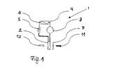
- Fig. 1 shows a schematic structure of a heat pump cycle 1 with an evaporator 2, a compressor 3, a condenser 4, a throttle point 5 and a connecting them flow circuit 6. Furthermore, is located in the flow direction behind the evaporator 2, a fan. 7
- the heat pump cycle 1 functions so that the fan 7 sucks incoming air 10 (ie, room air) through the evaporator 2. As a result, the supply air 10 is cooled in the evaporator 2.
- the surface temperature of the evaporator 2 is below the dew point temperature of the supply air 10. With supply air 10 at a temperature of 20 ° C and 50% RH, the dew point at 1013 hPa in about 9.3 ° C. If the surface temperature of the evaporator 2 is lower than this 9.3 ° C, the water vapor contained in the supply air 10 condenses within the evaporator 2.
- the cooled supply air 10 is led away after the evaporator 2 via the fan 7 as exhaust air 11.
- For a corresponding air channel 9 is provided.
- the condensate 13 of the supply air 10 formed in the evaporator 2 is collected in a condensate tank 12 and placed in a washing compartment of the dishwasher 8.
- the condensate 13 is collected until the dishwasher 8 is just before a new rinse and then in the Rinsing tank let in. In this way, the amount of liquid of the condensate 13 can be used for the following rinse.
- the refrigerant Due to the heat energy transferred from the supply air 10 to the refrigerant, the refrigerant can evaporate.
- the compressor 3 then sucks the gaseous refrigerant at low pressure and compresses it to a high pressure. In this case, the refrigerant is heated, wherein it includes approximately the sum of evaporation energy and drive energy of the compressor 3. This total energy is released again at the condenser 4. This is done via the condensation of the refrigerant within the condenser 4.
- the liquid refrigerant is then expanded via the throttle point 5 to a low pressure, where it can then evaporate again.
- Fig. 2 shows the heat pump cycle 1 according to Fig. 1 , which is installed in a dishwasher 8.
- the air channel 9 is additionally shown, in which the evaporator 2 is arranged.
- Fig. 3 shows the bottom portion of the dishwasher 8 according to Fig. 2 .
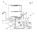
- Fig. 4 schematically shows a cross section through a dishwasher 8.
- the dishwasher 8 has a heat pump circuit 1 with an evaporator 2, a compressor 3, a condenser 4, a throttle point 5, a flow circuit 6 and a fan 7.
- a condensate container 12 is arranged below the evaporator 2.
- a condensate pump 14 the condensate 13 is sucked out of the condensate tank 12 and passed through a condensate line 15 in the washing of the dishwasher 8.
- a fill level sensor 17 is used to measure the amount of condensate 13 within the condensate container 12.
- a flow sensor 16 within the condensate line 15 measures the flow rate from the condensate container 12 into the wash chamber of the dishwasher 8.
- the condensate 13 is collected within the condensate tank 12.
- the condensate pump 14 conveys the condensate 13 via a condensate line 15 from the condensate tank 12 in the washing compartment of the dishwasher 8.
- the condensate pump 14 can be controlled.
- the dishwasher 8 the If necessary, add water inlets with condensate 13, which reduces the overall fresh water consumption of the dishwasher 8.
- a defined amount of fresh water for example two liters, is added to the collecting pot of the dishwasher 8.
- the intended amount of water for this rinse cycle minus the maximum possible amount of condensate is used for this subset.
- the circulation pump 18 is started at a low speed, for example, 2500 rpm, thereby ensuring stable pumping.
- the condensate 13 (or a partial amount of condensate 13) is added to the collecting pot of the dishwasher 8, wherein at the same time the rotational speed of the circulation pump 18 is increased until reaching the target speed with stable pump running.
- the speed in question may be 3750 rpm, for example.
- the speed of the circulation pump 18 can not be set to the setpoint speed for stable pumping. In this case, one or more further partial water inlets with fresh water or condensate 13 must be done to achieve the target speed in addition to a stable pump running at target speed of the circulation pump 18 is reached.
- a second method sequence envisages the use of the flow sensor 16 within the condensate line 15. According to this method, the entire existing in the condensate tank 12 condensate 13 is added to the washing and measured the appropriate amount by means of the flow sensor 16. Subsequently, the difference value between the actual amount of water of the condensate 13 and a desired amount is formed. The missing amount of water is compensated by fresh water and placed in the washing of the dishwasher 8.
- a fill level sensor 17 can be arranged within the condensate container 12, which already measures the amount of condensate available within the condensate container 12.
- Level sensor 17 a threatening overflow of the condensate tank 12 are sensed. This can then be prevented by switching on the condensate pump.
- the condensate line 15, starting from the condensate tank 12, can be guided either directly into the washing compartment of the dishwasher 8 or into other components of the dishwasher 8 fluidly connected to the washing compartment, for example into a collecting pot, which is located upstream of the washing compartment, or into a water inlet pocket ,
- the condensate pump 14 may be a diaphragm, vibratory, centrifugal or reciprocating pump.
Landscapes
- Engineering & Computer Science (AREA)
- Water Supply & Treatment (AREA)
- Washing And Drying Of Tableware (AREA)
Abstract
Description
- Die Erfindung betrifft ein Verfahren zum Betreiben einer Geschirrspülmaschine, wobei Zuluft durch einen Verdampfer geleitet wird, wobei die Zuluft innerhalb des Verdampfers Wärmeenergie an ein Kältemittel abgibt, wobei anschließend das verdampfte Kältemittel mittels eines Verdichters komprimiert wird, und wobei anschließend das komprimierte Kältemittel innerhalb eines Verflüssigers kondensiert wird und Wärmeenergie an Spülflotte abgibt. Die Erfindung betrifft darüber hinaus eine Geschirrspülmaschine zur Durchführung eines solchen Verfahrens.
- Die
DE 102011000042.9 beschreibt ein Verfahren zum Betreiben einer Geschirrspülmaschine, welche eine Luft- Wasser-Wärmepumpe zum Aufheizen von Spülflotte verwendet. In deren Wärmepumpenkreislauf wird Energie von einem gasförmigen Stoffstrom mit einem niedrigen Temperaturniveau auf einen flüssigen Stoffstrom mit einem höheren Temperaturniveau übertragen. Als Wärmequelle dient dabei die Raumluft am Aufstellungsort der Geschirrspülmaschine, d.h. zum Beispiel die Küchenluft. Die Wärmesenke ist die Spülflüssigkeit (Spülflotte) der Geschirrspülmaschine. - Ein Wärmepumpenkreislauf besteht im Wesentlichen aus vier Bauteilen, die strömungstechnisch über ein Rohrleitungssystem verbunden sind, in welchem ein Arbeitsmedium (Kältemittel) strömt. In Strömungsrichtung des Kältemittels sind die Bauteile so angeordnet, dass zuerst der Verdampfer (Wärmeübertrager), anschließend der Verdichter (Strömungsmaschine) und schließlich der Verflüssiger (Wärmeübertrager) durchströmt werden. Anschließend durchläuft das Kältemittel eine Drosselstelle.
- Für den Betrieb des Wärmepumpenkreislaufes wird zuerst flüssiges Kältemittel in den Verdampfer eingespritzt. Aufgrund des niedrigen Druckes im Verdampfer kann das Kältemittel Energie aufnehmen und bei niedrigen Temperaturen verdampfen. Anschließend saugt der Verdichter das gasförmige Kältemittel mit niedrigem Druck an und verdichtet es auf einen hohen Druck. Dabei wird das Kältemittel heiß. Das Kältemittel beinhaltet dadurch ungefähr die Summe aus Verdampfungsenergie und Antriebsenergie des Verdichters. Diese Energie wird innerhalb des Verflüssigers wieder abgegeben. Dies geschieht durch das Kondensieren des Kältemittels. Schließlich wird das flüssige Kältemittel mittels der Drosselstelle auf einen niedrigen Druck expandiert, wo es anschließend wieder verdampfen kann, um den Wärmepumpenkreislauf ein weiteres Mal zu durchlaufen.
- Damit dieser Wärmepumpenkreislauf funktioniert, muss dem Verdampfer Wärmeenergie zur Verfügung gestellt und dem Verflüssiger Wärme entzogen werden. Der Verdampfer erhält dabei wie zuvor beschrieben die notwendige Wärmeenergie zur Verdampfung des Kältemittels durch das Abkühlen von Zuluft (d.h. Raumluft), während der Verflüssiger die Wärmeenergie an Spülflotte der Geschirrspülmaschine abgibt.
- Obwohl sich das im Stand der Technik bekannte Verfahren zum Betreiben einer Geschirrspülmaschine mit einem Wärmepumpenkreislauf bewährt hat, besteht weiterer Verbesserungsbedarf, insbesondere bezüglich der Energieeffizienz der Geschirrspülmaschine und dabei insbesondere in Bezug auf den Wasserverbrauch.
- Es ist daher die Aufgabe der Erfindung, eine Geschirrspülmaschine und ein verbessertes Verfahren zum Betreiben einer Geschirrspülmaschine zur Verfügung zu stellen, wobei der Wasserverbrauch weiter reduziert wird und damit die Energieeffizienz der Geschirrspülmaschine steigt.
- Zur Lösung dieser Aufgabe wird mit der Erfindung ein Verfahren und eine Vorrichtung gemäß den unabhängigen Ansprüchen vorgeschlagen. Weiterbildungen ergeben sich aus den Unteransprüchen.
- Zum Aufheizen von Spülflotte, welche im Spülraum der Geschirrspülmaschine zum Reinigen von Spülgut eingesetzt wird, wird eine Luft-Wasser-Wärmepumpe verwendet. Diese umfasst einen Wärmepumpenkreislauf mit insbesondere einem Verdampfer, einem Verdichter und einem Verflüssiger. Dabei wird Zuluft durch einen Verdampfer geleitet, wobei die Zuluft innerhalb des Verdampfers Wärmeenergie an ein Kältemittel abgibt. Das hierbei verdampfte Kältemittel wird mittels des Verdichters komprimiert und anschließend das komprimierte Kältemittel innerhalb des Verflüssigers kondensiert. Dabei gibt es Wärmeenergie an Spülflotte ab. Durch diese Aufheizung wird die Spülflotte auf die zum Reinigen des Spülgutes vorgesehene und erfoderliche Temperatur gebracht.
- Erfindungsgemäß wird dabei innerhalb des Verdampfers gebildetes Kondensat gesammelt und das gesammelte Kondensat dem Spülraum der Geschirrspülmaschine zugeleitet. Die Überführung des Kondensats in den Spülraum kann vorzugsweise dann erfolgen, wenn es benötigt wird, insbesondere erfolgt sie programmgesteuert. Die gesammelte Kondensatmenge kann dann für einen wasserführenden Programmabschnitt eines Spülprogramms verwendet werden. Auf diese Weise kann der Wasserverbrauch der Geschirrspülmaschine gesenkt werden.
- Die Geschirrspülmaschine, etwa eine Haushaltgeschirrspülmaschine, weist einen mit einer Beschickungstür in an sich bekannter Weise verschließbaren Spülraum auf. Während eines Spülprogramms wird das im Spülraum befindliche Spülgut zunächst gespült und anschließend getrocknet. Das Spülen umfasst typischerweise mehrere wasserführende Programmabschnitte, etwa die Programmabschnitte REINIGEN und KLARSPÜLEN. Im Spülbetrieb, also während wasserführender Programmabschnitte ist der Spülraum durch die Beschickungstür verschlossen.
- Die Zuluft wird von außerhalb der Geschirrspülmaschine in das Geschirrspülmaschinengehäuse mittels einer Fördereinrichtung angesaugt und zum Verdampfer der Wärmepumpe geleitet. Eine Einleitung der Zuluft in den Spülraum findet nicht statt. Bei der Zuluft, welche die Wärmequelle der Wärmepumpe darstellt, handelt es sich somit um Raumluft, also Luft aus dem Aufstellungsraum der Geschirrspülmaschine, etwa der Küche, die insbesondere eine für derartige Räume übliche Umgebungstemperatur aufweist, also ca. 15 bis 25°C. Die Förderung der Zuluft bzw. Raumluft erfolgt während der Heizphase eines Spülprogramms, bei der Spülflotte aufgeheizt wird, insbesondere also während eines wasserführenden Programmabschnittes. Die Förderung der Zuluft erfolgt somit insbesondere bei geschlossener Beschickungstür.
- Das erfindungsgemäße Verfahren nutzt vorzugsweise das Prinzip der sogenannten nassen Kühlung. Bei der Kühlung von Gasen, insbesondere Luft, können im Wesentlichen zwei verschiedene Fälle unterschieden werden, die trockene Kühlung und die nasse Kühlung. Die trockene Kühlung bezeichnet dabei eine Kühlung ohne Wasserausscheidung, welche an einer kalten Wärmeübertragungsfläche erfolgt, die die Taupunkttemperatur der auftreffenden feuchten Luft nicht unterschreitet. Somit erfolgt bei der trockenen Kühlung kein Auskondensieren des Wasserdampfes, wodurch der absolute Wasserdampfgehalt der Luft konstant bleibt. Demgegenüber wird gemäß der Erfindung die Taupunkttemperatur der feuchten Luft unterschritten, so dass der Wasserdampf aus der Zuluft an den Verdampferoberflächen kondensiert. Der Luft wird somit das Wasser entzogen. Durch das Kondensieren der Zuluft, insbesondere des darin enthaltenen Wasserdampfes, ist ein wesentlich besserer Wärmeübergang an das Kältemittel möglich als nur aufgrund der trockenen Kühlung. Bei trockener Kühlung wären zur Erreichung des gleichen Wärmeüberganges wesentlich größere Wärmetauscherflächen notwendig bzw. eine höhere Luftmengenzufuhr. Dadurch ergäbe sich jedoch ein viel zu großer notwendiger Bauraum für den Wärmetauscher. Eine nasse Kühlung vermeidet die vorgenannten Probleme.
- Damit wird bewusst ein Nachteil in Kauf genommen, welcher durch die nasse Kühlung entsteht, nämlich die Bildung von Kondensat im Verdampfer. Bisher wird die Kondensation im Hinblick auf die den Verdampfer naheliegenden elektrischen und elektronischen Komponenten stets vermieden, weil dabei besondere Vorsichtsmaßnahmen getroffen werden müssen. Die Erfindung erkennt jedoch den Vorteil der effizienteren Energieübertragung durch nasse Kühlung, welcher den Nachteil der Flüssigkeitsbildung überwiegt.
- Das bei der nassen Kühlung anfallende Kondensat wird zur Verwendung in einem Programmabschnitt eines Spülprogramms der Geschirrspülmaschine genutzt. Um das Kondensat dabei besonders einfach in den Spülbehälter der Geschirrspülmaschine zu fördern, wird das gebildete Kondensat in einem Kondensatbehälter gesammelt und anschließend über eine Kondensatleitung in den Spülbehälter der Geschirrspülmaschine gegeben. Da bei einer erfindungsgemäßen Haushaltsgeschirrspülmaschine mit Luft-Wasser-Wärmepumpe, welche nach dem Prinzip der nassen Kühlung betrieben wird, die anfallende Kondensatmenge bis zu 800 ml betragen kann, wird bei der Nutzung dieser Kondensatmenge für den Spülgang die benötigte Menge Frischwasser erheblich reduziert. Dies trägt zur weiteren Resourceneinsparung der Geschirrspülmaschine bei.
- Zur Sammlung des im Verdampfer anfallenden Kondensats ist im Bereich des Verdampfers, vorzugsweise unterhalb des Verdampfers ein Kondensatbehälter angeordnet, in welchen das Kondensat durch Schwerkraftwirkung gelangen kann, z.B. vom Verdampfer abtropfen kann. Das innerhalb des Kondensatbehälters gesammelte Kondensat kann anschließend dem Spülraum der Geschirrspülmaschine zugeleitet werden. Hierfür ist eine Kondensatleitung vorhanden. Die Kondensatleitung kann den Kondensatbehälter insbesondere unmittelbar oder mittelbar mit dem Spülbehälter der Geschirrspülmaschine verbinden. So kann die Kondensatleitung etwa direkt an den Spülbehälter angeschlossen sein oder auch an mit dem Spülbehälter fluidtechnisch verbundenen Bauteile, wie etwa den Sammeltopf oder der Wassereinlauftasche. Insgesamt kann das Kondensat somit gleich oder auch in einem späteren Programmabschnitt eines Spülprogramms zur Bereitstellung der für einen Programmabschnitt benötigten Wassermenge genutzt werden.
- Die Erfindung sieht weiterhin vor, dass die Menge des gesammelten Kondensats gemessen wird. So kann die Menge des innerhalb des Kondensatbehälters gesammelten Kondensats etwa mittels eines in dem Kondensatbehälter angeordneten Füllstandssensors gemessen wird. Alternativ oder zusätzlich kann die Menge des innerhalb des Kondensatbehälters gesammelten Kondensats ebenfalls mittels eines in der Kondensatleitung angeordneten Durchflusssensors gemessen werden. Dadurch kann die Menge des gesammelten Kondensats zum einen bereits im Kondensatbehälter gemessen werden und zum anderen die aus dem Kondensatbehälter in den Spülbehälter überführte Menge oder Teilmenge des gesammelten Kondensats. Als Füllstandssensoren bzw. Durchflusssensoren können alle im Stand der Technik bekannten Sensoren verwendet werden. Die Mengenmessung kann insbesondere dazu genutzt werden, programmgesteuert eine Frischwassermenge zu bestimmen, die zusätzlich zum Kondensat in den Spülraum einzubringen ist, um insgesamt eine für einen Programmabschnitt eines Spülprogramms vorgegebene Spülfüssigkeitsmenge bereitzustellen.
- Die Erfindung sieht weiterhin vor, dass die für einen Spülgang der Geschirrspülmaschine benötigte Menge Wasser aus Frischwasser und Kondensat gebildet wird. Dabei trägt die Erfindung dem Umstand Rechnung, dass die für einen Spülgang benötigte Wassermenge die Menge des gesammelten Kondensats typischerweise überschreitet. Somit muss zur Bereitstellung einer ausreichenden Wassermenge gleichfalls Frischwasser zugegeben werden. Dabei stehen für die Mischung von Frischwasser und Kondensat zu einer ausreichenden Wassergesamtmenge zwei unterschiedliche Verfahren zur Verfügung.
- Eine erste Verfahrensvariante ist gekennzeichnet durch die Schritte Einleiten von Kondensat sowie einer vorgegebenen oder vorgebbaren Menge Frischwasser in den Spülraum, Betreiben einer die Spülflotte fördernde Umwälzpumpe mit einer Start-Drehzahl, Einleiten einer Ergänzungsmenge Frischwasser in den Spülraum und Erhöhung der Drehzahl der Umwälzpumpe.
- Gemäß dieser Verfahrensvariante wird für die Durchführung eines Programmabschnitts eines Spülprogramms, wie etwa Vorspülen, Reinigen, Zwischenspülen oder Klarspülen, in einem zunächst eine vorgegebene oder vorgebbare Menge Frischwasser sowie Kondensat aus dem Kondensatbehälter in den Spülraum gegeben. Beim Kondensat handelt es sich um die gesamte im Kondensatbehälter befindliche Kondensatmenge oder um eine Teilmenge davon.
- Die in den Spülraum eingeleitete vorgegebene oder vorgebbare Menge Frischwasser ist dabei insbesondere kleiner als die für die Durchführung dieses Programmabschnitts vorgesehene Spülflüssigkeitsmenge gewählt. Sie kann beispielsweise jener vorgesehenen Spülflüssigkeitsmenge abzüglich einer vorgegebenen maximalen Kondensatmenge entsprechen. Diese vorgegebene oder vorgebbare Menge Frischwasser reicht dabei insbesondere aber aus, um die Umwälzpumpe mit einer vorgegebenen, insbesondere niedrigen, Start-Drehzahl stabil, d.h. ohne Ansaugen von Luft aus dem Sammeltopf, zu betreiben. Die Start-Drehzahl ist dabei niedriger als eine für den Programmabschnitt vorgesehene Solldrehzahl. Der stabile bzw. instabile Pumpenlauf kann im Übrigen in an sich bekannter Weise über die Pumpen- bzw. Geräteelektronik sensiert werden, indem ein oder mehrere Betriebsparameter der Umwälzpumpe von der Geräteelektronik ausgewertet werden, wie in dem Patent
DE 102007011307B3 beschrieben. - Die Reihenfolge der Einleitung der vorgegebenen oder vorgebbaren Menge Frischwasser einerseits und des Kondensats andererseits in den Spülraum ist grundsätzlich beliebig. Wenn zunächst die Einleitung der vorgegebenen oder vorgebbaren Menge Frischwasser erfolgt, kann allerdings schon während der Einleitung des Kondensats die Umwälzpumpe in Betrieb sein, wodurch eine kürzere Spüldauer erreichbar ist.
- Mit höherer Spülflüssigkeitsmenge im Spülbehälter, kann die drehzahlregelbare Umwälzpumpe mit einer höheren Drehzahl als der Start-Drehzahl betrieben werden. Die gesammelte Kondensatmenge hängt jedoch stark von den Betriebsbedingungen und der Laufzeit der Wärmepumpe ab und ist daher nicht immer gleich groß. Somit ist nicht sichergestellt, dass die vorgesehene Spülflüssigkeitsmenge für den Programmabschnitt nach Einleitung der vorgegebene oder vorgebbare Menge Frischwasser und des
- Kondensats aus dem Kondensatbehälter in den Spülraum bereits erreicht ist.
- Falls nach Einleitung der vorgegebene oder vorgebbare Menge Frischwasser und des Kondensats aus dem Kondensatbehälter in den Spülbehälter die Umwälzpumpe noch nicht mit ihrer, insbesondere für den Programmabschnitt des Spülprogramms, vorgegebenen Solldrehzahl stabil betrieben werden kann und/oder eine vorgegebene Spülflüssigkeitsmenge im Spülbehälter noch nicht erreicht ist, wird ein Ergänzungsschritt vorgenommen, bei dem zunächst eine Ergänzungsmenge Frischwasser in den Spülraum eingeleitet und dabei oder anschließend eine die Drehzahl der Umwälzpumpe erhöht wird.
- Vorzugsweise erfolgt der Ergänzungsschritt, insbesondere das Einleiten einer Ergänzungsmenge Frischwasser in den Spülraum somit abhängig von mindestens einem Betriebsparameter der Umwälzpumpe und/oder der Menge der im Spülraum befindlichen Spülflüssigkeit.
- Außerdem wird der Ergänzungsschritt, also das Einleiten einer Ergänzungsmenge Frischwasser in den Spülraum und nachfolgende und parallele Erhöhung der Drehzahl der Umwälzpumpe mehrfach wiederholt bis die Drehzahl der Umwälzpumpe eine vorgegebene oder vorgebbare Solldrehzahl und/oder die im Spülraum befindliche Spülflüssigkeitsmenge eine vorgegebene oder vorgebbare Sollmenge erreicht hat.
- Mit dieser ersten Verfahrensvariante ist keine direkte Messung der Kondensatmenge, insbesondere kein Füllstandssensor im Kondensatbehälter oder Durchflussmesser in der Kondensatleitung notwendig. Man kann ohne zusätzliche Mittel den Frischwasserbedarf um die angefallene Kondensatmenge verringern.
- Eine zweite Verfahrensvariante sieht vor, dass die Menge des gesammelten Kondensats gemessen wird, insbesondere kann der Kondensatbehälter hierfür einen Füllstandssensor und/oder die Kondensatleitung einen Durchflusssensor aufweisen. Dadurch ist besonders einfach eine Bestimmung der Kondensatmenge möglich. Entweder kann die Kondensatmenge dabei direkt als Füllstand innerhalb des Kondensatbehälters gemessen werden, oder die Bestimmung der Kondensatmenge erfolgt während des Durchflusses des Kondensats von dem Kondensatbehälter in den Spülraum. Vorteilhafterweise kann dann die Differenz zu der für einen Programmabschnitt eines Spülprogramms der Geschirrspülmaschine benötigten Spülflüssigkeitsmenge berechnet werden. Diese
- Differenz wird programmgesteuert durch Zugabe von Frischwasser ausgeglichen.
- Vorzugsweise wird ein Spülprogramm aus Hygienegründen mit leerem Kondensatbehälter gestartet. Während eines ersten Programmabschnitts, beispielsweise Reinigen, wird mit der Wärmepumpe aufgeheizt. Hierbei fallen bis zu 800ml Kondensat an. Das gesammelte Kondensat wird in einem späteren Programmabschnitts, z.B. Zwischenspülen oder Klarspülen, verwendet.
- In einem weiteren Aspekt wird eine Geschirrspülmaschine, insbesondere zur Ausführung des vorgenannten Verfahrens, vorgeschlagen, welche einen Spülraum zur Einbringung von zu spülendem Spülgut, und einen Wärmepumpenkreislauf umfasst, welcher einen Verdampfer, einen Verdichter und einen Verflüssiger aufweist. Zur Reduzierung der für einen Spülgang benötigten Frischwassermenge wird die Geschirrspülmaschine so variiert, dass im Bereich des Verdampfers ein Kondensatbehälter zum Sammeln von in dem Verdampfer gebildeten Kondensat angeordnet ist, und dass eine Kondensatleitung vorhanden ist, mittels der das Kondensat aus dem Kondensatbehälter dem Spülraum zuführbar ist.
- Durch die in Reihe angeordneten Bauteile Verdampfer, Kondensatbehälter, Kondensatleitung und Spülraum der Geschirrspülmaschine lässt sich eine besonders einfache Abführung des Kondensats von dem Verdampfer in den Spülraum sicherstellen. Vorteilhaft ist der Kondensatbehälter dabei so angeordnet, dass das Kondensat durch Schwerkraftwirkung in den Kondensatbehälter gelangt. Der Kondensatbehälter kann etwa unter dem Verdampfer angeordnet sein, insbesondere derart dass das im Verdampfer anfallende Kondensat direkt in den Kondensatbehälter abtropft. Der Kondensatbehälter kann auch räumlich getrennt, d.h. beabstandet vom Verdampfer angeordnet sein. Insbesondere kann das Verdampfergehäuse, die Luftführung durch den Verdampfer und/oder zusätzliche Leitungen auch so ausgebildet sein, dass das Kondensat in den Kondensatbehälter durch Schwerkraftwirkung fliessen kann.
- Der Verdampfer weist vorzugsweise eine Vielzahl von Lamellen, d.h. dünne Metallplatten auf, welche parallel oder annähernd parallel zueinander angeordnet ist. Die Zuluft strömt zwischen benachbarten Lamellen hindurch. Die Lamellen dienen als Kondensationsfläche für die Zuluft bzw. dem darin enthaltenen Wasserdampf.
- Um eine besonders große Ausbeute an Kondensat aus den Verdampfer zu erzielen, ist es vorteilhaft, dass die Lamellen des Verdampfers hydrophil beschichtet sind. Dies stellt sicher, dass sich an den Lamellen nur ein dünner Wasserfilm bildet der ungehindert ablaufen kann.
- Weiterhin sollten die Lamellen durchgängig gerade ausgebildet sein und keine Rippung aufweisen. Vorteilhaft ist zudem, wenn die Lamellen in Schwerkraftrichtung ausgerichtet sind, so dass das Ablaufen des Kondensats unterstützt wird, d.h. das Kondensat fließt senkrecht die Lamellenflächen hinab. Die plattenförmigen Lamellen weisen zumindest eine Ecke auf und sind in der Geschirrspülmaschine vorzugsweise jeweils so angeordnet, dass eine Ecke der Lamelle einen tiefstgelegenen Punkt einer Lamelle darstellt, auf den Kanten der Lamelle schräg zulaufen. Eine solche Anordnung kann einfach durch eine Neigung des kastenförmigen Verdampfers erreicht werden. Auf diese Weise kann zusätzlich der Ablauf des Kondensats aus dem Verdampfer verbessert werden. Diese speziellen Ausbildungen des Verdampfers ermöglichen insgesamt ein vereinfachtes Ablaufen des Kondensates aus dem Verdampfer in den Kondensatbehälter.
- Eine weitere vorteilhafte Ausgestaltung des Verdampfers sieht eine hydrophobe Beschichtung des Verdampfers vor, welche das Kondensat in großen Tropfen ablaufen lässt.
- Weitere Merkmale und Vorteile der Erfindung sind im Folgenden anhand der Figuren näher beschrieben. Dabei zeigen:
- Fig. 1
- einen schematischen Aufbau eines Wärmepumpenkreislaufes;
- Fig. 2
- den Wärmepumpenkreislauf gemäß
Fig. 1 , eingebaut in eine Geschirrspülmaschine; - Fig. 3
- eine Seitenansicht der Geschirrspülmaschine gemäß
Fig. 2 ; - Fig. 4
- schematisch einen Querschnitt durch eine Geschirrspülmaschine.
-
Fig. 1 zeigt einen schematischen Aufbau eines Wärmepumpenkreislaufes 1 mit einem Verdampfer 2, einem Verdichter 3, einem Verflüssiger 4, einer Drosselstelle 5 und einem diese verbindenden Strömungskreislauf 6. Des Weiteren befindet sich in Strömungsrichtung hinter dem Verdampfer 2 ein Ventilator 7. - Der Wärmepumpenkreislauf 1 funktioniert so, dass der Ventilator 7 Zuluft 10 (d.h. Raumluft) durch den Verdampfer 2 hindurch saugt. Hierdurch wird die Zuluft 10 im Verdampfer 2 abgekühlt. Um die erfindungsgemäße nasse Kühlung zu gewährleisten, befindet sich die Oberflächentemperatur des Verdampfers 2 unter der Taupunkttemperatur der Zuluft 10. Bei Zuluft 10 mit einer Temperatur von 20°C und 50% r.F. beträgt die Taupunkttemperatur bei 1013 hPa in etwa 9,3°C. Sofern die Oberflächentemperatur des Verdampfers 2 geringer als diese 9,3°C ist, kondensiert der in der Zuluft 10 enthaltene Wasserdampf innerhalb des Verdampfers 2. Damit eine ausreichende Heizleistung des Wärmepumpenkreislaufes 1 sichergestellt ist, muss eine ausreichende Menge Zuluft 10 durch den Verdampfer 2 strömen. Hierzu empfiehlt sich die Verwendung eines Ventilators 7, welcher in Strömungsrichtung hinter dem Verdampfer 2 angeordnet ist. Hierzu ist beispielsweise ein Luftvolumenstrom von 100 m3/h geeignet. Bei einem Luftvolumenstrom von 100m3/h, der um eine Temperaturdifferenz von 10 K durch den Verdampfer 2 abgekühlt wird, werden bereits im Falle einer trockenen Kühlung ca. 330 W Kühlleistung erzeugt. Dies reicht aus, um eine haushaltsübliche Geschirrspülmaschine 8 in akzeptabler Zeitspanne mittels des Wärmepumpenkreislaufes 1 aufzuheizen. Bei nasser Kühlung erhöht sich die Kühlleistung je nach Zuluftfeuchte entsprechend. Die Heizleistung des Wärmepumpenkreislaufes 1 setzt sich dann näherungsweise aus der tatsächlichen Kühlleistung des Verdampfers 2 und der Antriebsleistung des nachfolgenden Verdichters 3 zusammen. Dabei ergeben sich je nach Antriebsleistung des Verdichters und Wirkungsgrad der Anlage Heizleistungen zwischen 130 W und 2000 W.
- Die abgekühlte Zuluft 10 wird nach dem Verdampfer 2 über den Ventilator 7 als Abluft 11 weggeleitet. Dafür ist ein entsprechender Luftkanal 9 vorgesehen.
- Das im Verdampfer 2 gebildete Kondensat 13 der Zuluft 10 wird in einem Kondensatbehälter 12 gesammelt und in einen Spülbehälter der Geschirrspülmaschine 8 gegeben. Das Kondensat 13 wird dabei so lange gesammelt, bis sich die Geschirrspülmaschine 8 kurz vor einem neuen Spülgang befindet und sodann in den Spülbehälter eingelassen. Hierdurch kann die Flüssigkeitsmenge des Kondensats 13 für den folgenden Spülgang genutzt werden.
- Durch die von der Zuluft 10 auf das Kältemittel übergeleitete Wärmeenergie, kann das Kältemittel verdampfen. Der Verdichter 3 saugt anschließend das gasförmige Kältemittel mit niedrigem Druck an und verdichtet es auf einen hohen Druck. Dabei wird das Kältemittel erhitzt, wobei es annähernd die Summe aus Verdampfungsenergie und Antriebsenergie des Verdichters 3 beinhaltet. Diese Gesamtenergie wird am Verflüssiger 4 wieder abgegeben. Dies geschieht über die Kondensation des Kältemittels innerhalb des Verflüssigers 4. Das flüssige Kältemittel wird anschließend über die Drosselstelle 5 auf einen niedrigen Druck expandiert, wo es anschließend wieder verdampfen kann.
-
Fig. 2 zeigt den Wärmepumpenkreislauf 1 gemäßFig. 1 , welcher in einer Geschirrspülmaschine 8 eingebaut ist. Hier ist zusätzlich der Luftkanal 9 dargestellt, in welchem der Verdampfer 2 angeordnet ist. -
Fig. 3 zeigt den Bodenbereich der Geschirrspülmaschine 8 gemäßFig. 2 . -
Fig. 4 zeigt schematisch einen Querschnitt durch eine Geschirrspülmaschine 8. Die Geschirrspülmaschine 8 verfügt über einen Wärmepumpenkreislauf 1 mit einem Verdampfer 2, einem Verdichter 3, einem Verflüssiger 4, einer Drosselstelle 5, einem Strömungskreislauf 6 und einem Ventilator 7. Zum Sammeln des am Verdampfer 2 entstehenden Kondensats 13 ist unterhalb des Verdampfers 2 ein Kondensatbehälter 12 angeordnet. Mittels einer Kondensatpumpe 14 wird das Kondensat 13 aus dem Kondensatbehälter 12 abgesaugt und durch eine Kondensatleitung 15 in den Spülbehälter der Geschirrspülmaschine 8 gegeben. Zur Messung der Menge des Kondensats 13 innerhalb des Kondensatbehälters 12 dient ein Füllstandssensor 17. Ein Durchflusssensor 16 innerhalb der Kondensatleitung 15 misst den Durchfluss von dem Kondensatbehälter 12 in den Spülraum der Geschirrspülmaschine 8. - Bei der vorgeschlagenen Lösung gemäß
Fig. 4 wird das Kondensat 13 innerhalb des Kondensatbehälters 12 gesammelt. Die Kondensatpumpe 14 fördert das Kondensat 13 über eine Kondensatleitung 15 aus dem Kondensatbehälter 12 in den Spülraum der Geschirrspülmaschine 8. Mittels der Geräteelektronik kann die Kondensatpumpe 14 angesteuert werden. Durch diese Ausgestaltung kann die Geschirrspülmaschine 8 die Wassereinläufe bei Bedarf mit Kondensat 13 ergänzen, wodurch sich der Frischwasserverbrauch der Geschirrspülmaschine 8 insgesamt verringert. - Für die Bereitstellung der während eines Spülprogramms benötigten Wassermenge ergeben sich zwei mögliche Verfahrensabläufe.
- In einer ersten erfindungsgemäßen Ausgestaltung wird eine definierte Menge Frischwasser, beispielsweise zwei Liter, in den Sammeltopf der Geschirrspülmaschine 8 gegeben. Vorteilhafterweise wird für diese Teilmenge die für diesen Spülgang vorgesehenen Wassermenge abzüglich der maximal möglichen Kondensatmenge verwendet. Anschließend wird die Umwälzpumpe 18 mit niedriger Drehzahl, beispielsweise 2500 Umdrehung/min gestartet, wodurch ein stabiler Pumpenlauf sichergestellt wird. Anschließend wird das Kondensat 13 (oder eine Teilmenge Kondensat 13) in den Sammeltopf der Geschirrspülmaschine 8 gegeben, wobei gleichzeitig die Drehzahl der Umwälzpumpe 18 bis zum Erreichen der Solldrehzahl bei stabilem Pumpenlauf erhöht wird. Die betreffende Drehzahl kann beispielsweise 3750 Umdrehung/min betragen. Reicht die Kondensatmenge nicht aus, kann die Drehzahl der Umwälzpumpe 18 nicht auf die Solldrehzahl für stabilen Pumpenlauf eingestellt werden. Dabei müssen zur Erreichung der Solldrehzahl zusätzlich ein oder mehrere weitere Teilwassereinläufe mit Frischwasser oder Kondensat 13 erfolgen, bis ein stabiler Pumpenlauf bei Solldrehzahl der Umwälzpumpe 18 erreicht ist.
- Ein zweiter Verfahrensablauf sieht die Verwendung des Durchflusssensors 16 innerhalb der Kondensatleitung 15 vor. Nach diesem Verfahren wird das gesamte im Kondensatbehälter 12 vorhandene Kondensat 13 in den Spülbehälter gegeben und die entsprechende Menge mittels des Durchflusssensors 16 gemessen. Anschließend wird der Differenzwert zwischen der Istwassermenge des Kondensats 13 und einer Sollmenge gebildet. Die fehlende Wassermenge wird durch Frischwasser ausgeglichen und in den Spülbehälter der Geschirrspülmaschine 8 gegeben.
- Weiterhin kann innerhalb des Kondensatbehälters 12 ein Füllstandssensor 17 angeordnet sein, welcher die zur Verfügung stehende Kondensatmenge bereits innerhalb des Kondensatbehälters 12 misst.
- Bei unvorhergesehenen starken Kondensatanfall, kann des Weiteren mittels des
- Füllstandssensor 17 ein drohender Überlauf des Kondensatbehälters 12 sensiert werden. Dieser kann dann durch Einschalten der Kondensatpumpe verhindert werden.
- Weiterhin kann die Kondensatleitung 15 ausgehend vom Kondensatbehälter 12 entweder direkt in den Spülbehälter der Geschirrspülmaschine 8 geführt werden oder in andere mit dem Spülbehälter fluidtechnisch verbundene Bauteile der Geschirrspülmaschine 8, etwa in einen Sammeltopf, welcher sich in Strömungsrichtung vor dem Spülbehälter befindet, oder in eine Wassereinlauftasche.
- Die Kondensatpumpe 14 kann eine Membran-, Vibrations-, Kreisel- oder Hubkolbenpumpe sein.
-
- 1
- Wärmepumpenkreislauf
- 2
- Verdampfer
- 3
- Verdichter
- 4
- Verflüssiger
- 5
- Drosselstelle
- 6
- Strömungskreislauf
- 7
- Ventilator
- 8
- Geschirrspülmaschine
- 9
- Luftkanal
- 10
- Zuluft
- 11
- Abluft
- 12
- Kondensatbehälter
- 13
- Kondensat
- 14
- Kondensatpumpe
- 15
- Kondensatleitung
- 16
- Durchflusssensor
- 17
- Füllstandssensor
- 18
- Umwälzpumpe
Claims (11)
- Verfahren zum Betreiben einer Geschirrspülmaschine (8), wobei Zuluft (10) durch einen Verdampfer (2) geleitet wird, wobei die Zuluft (10) innerhalb des Verdampfers (2) Wärmeenergie an ein Kältemittel abgibt, wobei anschließend das verdampfte Kältemittel mittels eines Verdichters (3) komprimiert wird, und wobei anschließend das komprimierte Kältemittel innerhalb eines Verflüssigers (4) kondensiert wird und Wärmeenergie an Spülflotte abgibt,
dadurch gekennzeichnet,
dass innerhalb des Verdampfers (2) gebildetes Kondensat (13) gesammelt und das gesammelte Kondensat (13) dem Spülraum der Geschirrspülmaschine (8) zugeleitet wird. - Verfahren nach Anspruch 1,
dadurch gekennzeichnet,
dass die Menge des gesammelten Kondensats (13) und/oder die Menge des dem Spülraum der Geschirrspülmaschine (8) zugeleiteten Kondensats gemessen wird. - Verfahren nach einem der Ansprüche 1 bis 2,
dadurch gekennzeichnet,
dass die für einen Programmabschnitt eines Spülprogramms benötigte Spülflüssigkeitsmenge aus Frischwasser und Kondensat (13) gebildet wird. - Verfahren nach einem der Ansprüche 1 bis 3,
gekennzeichnet durch die Schritte,- Einleiten von Kondensat (13) sowie einer vorgegebenen oder vorgebbaren Menge Frischwasser in den Spülraum- Betreiben einer die Spülflotte fördernde Umwälzpumpe (18) mit einer Start-Drehzahl- Einleiten einer Ergänzungsmenge Frischwasser in den Spülraum- Erhöhung der Drehzahl der Umwälzpumpe (18). - Verfahren nach Anspruch 4,
dadurch gekennzeichnet,
dass das Einleiten einer Ergänzungsmenge Frischwasser in den Spülraum abhängig von mindestens einem Betriebsparameter der Umwälzpumpe (18) und/oder der Menge der im Spülraum befindlichen Spülflüssigkeit erfolgt. - Verfahren nach einem der Ansprüche 4 bis 5,
dadurch gekennzeichnet,
dass die Schritte Einleiten einer Ergänzungsmenge Frischwasser in den Spülraum und Erhöhung der Drehzahl der Umwälzpumpe (18) mehrfach wiederholt werden bis die Drehzahl der Umwälzpumpe (18) eine vorgegebene oder vorgebbare Solldrehzahl und/oder die im Spülraum befindliche Spülflüssigkeitsmenge eine vorgegebene oder vorgebbare Sollmenge erreicht hat. - Verfahren nach einem der vorgehenden Ansprüche,
dadurch gekennzeichnet,
dass die innerhalb des Kondensatbehälters (12) gesammelte Menge Kondensat (13) in den Spülraum der Geschirrspülmaschine (8) gegeben wird, dass anschließend die Differenz zu der für einen Programmabschnitt eines Spülprogramms der Geschirrspülmaschine (8) vorgesehene Spülflüssigkeitsmenge berechnet wird, und dass diese Differenz durch Zugabe einer Ergänzungsmenge Frischwasser ausgeglichen wird. - Geschirrspülmaschine (8) mit einem Spülraum zur Einbringung von zu spülendem Spülgut, und mit einem Wärmepumpenkreislauf (1) zum Aufheizen der Spülflotte, welcher einen Verdampfer (2), einen Verdichter (3) und einen Verflüssiger (4) aufweist,
dadurch gekennzeichnet,
dass im Bereich des Verdampfers (2) ein Kondensatbehälter (12) zum Sammeln von in dem Verdampfer (2) gebildeten Kondensat (13) angeordnet ist, und dass eine Kondensatleitung (15) vorhanden ist, mittels der das im Kondensatbehälter (12) gesammelte Kondensat (13) dem Spülraum zuführbar ist. - Geschirrspülmaschine (8) nach Anspruch 8,
dadurch gekennzeichnet,
dass der Kondensatbehälter (12) einen Füllstandssensor (17) aufweist und/oder dass die Kondensatleitung (15) einen Durchflusssensor (16) aufweist. - Geschirrspülmaschine (8) nach einem der Ansprüche 8 bis 9,
dadurch gekennzeichnet,
dass der Verdampfer (2) eine Vielzahl von als Kondensationsfläche wirkende Lamellen aufweist. - Geschirrspülmaschine (8) nach einem der Ansprüche 8 bis 10,
dadurch gekennzeichnet,
dass der Verdampfer (2) eine hydrophile Beschichtung oder eine hydrophobe Beschichtung aufweist.
Applications Claiming Priority (1)
| Application Number | Priority Date | Filing Date | Title |
|---|---|---|---|
| DE102012105906.3A DE102012105906A1 (de) | 2012-07-03 | 2012-07-03 | Geschirrspülmaschine und Verfahren zum Betreiben einer Geschirrspülmaschine |
Publications (3)
| Publication Number | Publication Date |
|---|---|
| EP2682037A2 true EP2682037A2 (de) | 2014-01-08 |
| EP2682037A3 EP2682037A3 (de) | 2014-09-10 |
| EP2682037B1 EP2682037B1 (de) | 2016-03-02 |
Family
ID=48795542
Family Applications (1)
| Application Number | Title | Priority Date | Filing Date |
|---|---|---|---|
| EP13401067.7A Active EP2682037B1 (de) | 2012-07-03 | 2013-07-02 | Geschirrspülmaschine und Verfahren zum Betreiben einer Geschirrspülmaschine |
Country Status (2)
| Country | Link |
|---|---|
| EP (1) | EP2682037B1 (de) |
| DE (1) | DE102012105906A1 (de) |
Cited By (14)
| Publication number | Priority date | Publication date | Assignee | Title |
|---|---|---|---|---|
| WO2016089332A1 (en) | 2014-12-03 | 2016-06-09 | Arcelik Anonim Sirketi | A heat pump dishwasher |
| WO2016089331A1 (en) | 2014-12-03 | 2016-06-09 | Arcelik Anonim Sirketi | A heat pump dishwasher |
| WO2016177718A1 (en) | 2015-05-06 | 2016-11-10 | Arcelik Anonim Sirketi | A dishwasher comprising a heat pump |
| CN108700309A (zh) * | 2016-03-02 | 2018-10-23 | 恩杰公司 | 用于通风的系统、方法和过滤器 |
| WO2019034373A1 (en) * | 2017-08-18 | 2019-02-21 | Arcelik Anonim Sirketi | DISHWASHER COMPRISING A HEAT PUMP |
| WO2019037979A1 (en) | 2017-08-23 | 2019-02-28 | Arcelik Anonim Sirketi | DISHWASHER COMPRISING A HEAT PUMP |
| WO2019129404A1 (en) * | 2017-12-25 | 2019-07-04 | Arcelik Anonim Sirketi | A heat pump dishwasher with decreased water consumption |
| WO2019192882A1 (en) | 2018-04-02 | 2019-10-10 | Arcelik Anonim Sirketi | A washer with heat pump and the control method thereof |
| WO2019233809A1 (en) * | 2018-06-04 | 2019-12-12 | Arcelik Anonim Sirketi | Heat pump dishwasher with enhanced evaporator capacity |
| WO2020057843A1 (en) * | 2018-09-17 | 2020-03-26 | Arcelik Anonim Sirketi | A dishwasher comprising a heat pump |
| WO2020064254A1 (en) | 2018-09-25 | 2020-04-02 | Arcelik Anonim Sirketi | A heat pump dishwasher comprising an evaporator tray |
| US11357384B2 (en) | 2018-11-27 | 2022-06-14 | Lg Electronics Inc. | Control method for dish washer |
| US11412910B2 (en) | 2018-11-27 | 2022-08-16 | Lg Electronics Inc. | Dish washer |
| US11576552B2 (en) | 2018-11-27 | 2023-02-14 | Lg Electronics Inc. | Dish washer |
Families Citing this family (1)
| Publication number | Priority date | Publication date | Assignee | Title |
|---|---|---|---|---|
| EP3718460B1 (de) * | 2019-04-05 | 2023-01-11 | Miele & Cie. KG | Geschirrspülmaschine, insbesondere haushaltsgeschirrspülmaschine |
Citations (2)
| Publication number | Priority date | Publication date | Assignee | Title |
|---|---|---|---|---|
| DE102007011307B3 (de) | 2007-03-06 | 2008-08-21 | Miele & Cie. Kg | Verfahren zur Durchführung eines Wassereinlaufs in den Spülbehälter einer Spülmaschine |
| DE102011000042A1 (de) | 2011-01-05 | 2012-07-05 | Miele & Cie. Kg | Verfahren zum Durchführen eines Spülprogramms |
Family Cites Families (9)
| Publication number | Priority date | Publication date | Assignee | Title |
|---|---|---|---|---|
| FR2325350A1 (fr) * | 1975-08-29 | 1977-04-22 | Bonnet Ets | Systeme de chauffage et de regulation de temperature d'un liquide et machine a laver la vaisselle comportant un tel systeme |
| DE3214216A1 (de) * | 1980-12-20 | 1983-10-27 | Stierlen-Maquet Ag, 7550 Rastatt | Waermerueckgewinnungseinrichtung fuer geschirrspuelmaschinen |
| DE3204396C2 (de) * | 1982-02-09 | 1983-12-08 | Bosch-Siemens Hausgeräte GmbH, 7000 Stuttgart | Haushalt-Wäschetrockner mit einem oben angeordneten Kondensat-Sammelbehälter |
| DE4330456C1 (de) * | 1993-09-08 | 1995-03-16 | Blomberg Werke Gmbh | Wäschetrockner |
| DE10023346A1 (de) * | 2000-05-12 | 2001-11-15 | Diehl Ako Stiftung Gmbh & Co | Vorrichtung zum Trocknen von Geschirr in einer Geschirrspülmaschine |
| DE102007025262A1 (de) * | 2007-05-30 | 2007-10-25 | Meiko Maschinenbau Gmbh & Co. Kg | Reinigungsgerät mit Mikrowellentrocknung |
| WO2009080577A1 (de) * | 2007-12-20 | 2009-07-02 | BSH Bosch und Siemens Hausgeräte GmbH | Wäschetrocknungsgerät mit einem prozessluftkanal |
| DE102010002661A1 (de) * | 2010-03-08 | 2011-09-08 | BSH Bosch und Siemens Hausgeräte GmbH | Vorrichtung zum Zuführen von Spülwasser, Hausgerät mit einer solchen Vorrichtung und Verfahren zum Zuführen von Spülwasser |
| DE102010027739A1 (de) * | 2010-04-14 | 2011-10-20 | BSH Bosch und Siemens Hausgeräte GmbH | Wasserweiche für ein wasserführendes Hausgerät |
-
2012
- 2012-07-03 DE DE102012105906.3A patent/DE102012105906A1/de not_active Withdrawn
-
2013
- 2013-07-02 EP EP13401067.7A patent/EP2682037B1/de active Active
Patent Citations (2)
| Publication number | Priority date | Publication date | Assignee | Title |
|---|---|---|---|---|
| DE102007011307B3 (de) | 2007-03-06 | 2008-08-21 | Miele & Cie. Kg | Verfahren zur Durchführung eines Wassereinlaufs in den Spülbehälter einer Spülmaschine |
| DE102011000042A1 (de) | 2011-01-05 | 2012-07-05 | Miele & Cie. Kg | Verfahren zum Durchführen eines Spülprogramms |
Cited By (16)
| Publication number | Priority date | Publication date | Assignee | Title |
|---|---|---|---|---|
| WO2016089332A1 (en) | 2014-12-03 | 2016-06-09 | Arcelik Anonim Sirketi | A heat pump dishwasher |
| WO2016089331A1 (en) | 2014-12-03 | 2016-06-09 | Arcelik Anonim Sirketi | A heat pump dishwasher |
| US20170325651A1 (en) * | 2014-12-03 | 2017-11-16 | Arcelik Anonim Sirketi | Heat pump dishwasher |
| WO2016177718A1 (en) | 2015-05-06 | 2016-11-10 | Arcelik Anonim Sirketi | A dishwasher comprising a heat pump |
| CN108700309B (zh) * | 2016-03-02 | 2021-03-12 | 恩杰公司 | 用于通风的系统、方法和过滤器 |
| CN108700309A (zh) * | 2016-03-02 | 2018-10-23 | 恩杰公司 | 用于通风的系统、方法和过滤器 |
| WO2019034373A1 (en) * | 2017-08-18 | 2019-02-21 | Arcelik Anonim Sirketi | DISHWASHER COMPRISING A HEAT PUMP |
| WO2019037979A1 (en) | 2017-08-23 | 2019-02-28 | Arcelik Anonim Sirketi | DISHWASHER COMPRISING A HEAT PUMP |
| WO2019129404A1 (en) * | 2017-12-25 | 2019-07-04 | Arcelik Anonim Sirketi | A heat pump dishwasher with decreased water consumption |
| WO2019192882A1 (en) | 2018-04-02 | 2019-10-10 | Arcelik Anonim Sirketi | A washer with heat pump and the control method thereof |
| WO2019233809A1 (en) * | 2018-06-04 | 2019-12-12 | Arcelik Anonim Sirketi | Heat pump dishwasher with enhanced evaporator capacity |
| WO2020057843A1 (en) * | 2018-09-17 | 2020-03-26 | Arcelik Anonim Sirketi | A dishwasher comprising a heat pump |
| WO2020064254A1 (en) | 2018-09-25 | 2020-04-02 | Arcelik Anonim Sirketi | A heat pump dishwasher comprising an evaporator tray |
| US11357384B2 (en) | 2018-11-27 | 2022-06-14 | Lg Electronics Inc. | Control method for dish washer |
| US11412910B2 (en) | 2018-11-27 | 2022-08-16 | Lg Electronics Inc. | Dish washer |
| US11576552B2 (en) | 2018-11-27 | 2023-02-14 | Lg Electronics Inc. | Dish washer |
Also Published As
| Publication number | Publication date |
|---|---|
| EP2682037A3 (de) | 2014-09-10 |
| DE102012105906A1 (de) | 2014-01-09 |
| EP2682037B1 (de) | 2016-03-02 |
Similar Documents
| Publication | Publication Date | Title |
|---|---|---|
| EP2682037B1 (de) | Geschirrspülmaschine und Verfahren zum Betreiben einer Geschirrspülmaschine | |
| EP2682036A2 (de) | Geschirrspülmaschine und Verfahren zum Aufheizen von Spülflotte in einer Geschirrspülmaschine | |
| EP2064982B1 (de) | Geschirrspüler mit Wärmepumpe | |
| EP1284627B1 (de) | Vorrichtung zum trocknen von geschirr in einer geschirrspülmaschine | |
| DE102014001944B4 (de) | Geschirrspülmaschine und Steuerverfahren derselben | |
| EP2777471B1 (de) | Geschirrspülautomat, insbesondere haushaltsgeschirrspülmaschine | |
| EP2777474B1 (de) | Geschirrspülautomat | |
| EP1825800B1 (de) | Geschirrspüler mit Mitteln zum Abziehen von Feuchte aus dem Bottich | |
| EP2682039B1 (de) | Geschirrspülmaschine mit einer Wärmepumpe | |
| EP2057928A2 (de) | Geschirrspülmaschine mit Latentwärmespeicher | |
| DE102016203414B9 (de) | Wärmepumpe mit einem Fremdgassammelraum, Verfahren zum Betreiben einer Wärmepumpe und Verfahren zum Herstellen einer Wärmepumpe | |
| DE102012209826A1 (de) | Kondensationstrockner mit einer Pumpe sowie Verfahren zu seinem Betrieb | |
| WO2009095316A1 (de) | Kondensationstrockner mit kondensatwanne und -behälter sowie verfahren zu seinem betrieb | |
| EP3375345A1 (de) | Geschirrspülmaschine, insbesondere haushaltsgeschirrspülmaschine | |
| EP3410914A1 (de) | Haushaltsgeschirrspülmaschine sowie verfahren zum betreiben einer solchen | |
| EP2697578B1 (de) | Kältegerät mit verdunstungsschale | |
| EP2832241B1 (de) | Vorrichtung und verfahren zur kondensation eines dampfes in einer vakuumkammer | |
| WO2006018216A1 (de) | Absorptionskältemaschine | |
| DE102004012978B4 (de) | Kühlgerät für einen Schaltschrank | |
| WO2014095465A1 (de) | Haushalts-wäschetrocknungsgerät mit reinigungseinrichtung für flusenfilter | |
| EP2682040B1 (de) | Verfahren zum Betreiben einer Geschirrspülmaschine | |
| DE102017115585B4 (de) | Geschirrspülmaschine und Verfahren zum Betreiben einer Geschirrspülmaschine | |
| EP2378227A1 (de) | Kühlschrank | |
| DE102010028441A1 (de) | Waschtrockner mit einer Wärmepumpe und Verfahren zu seinem Betrieb | |
| EP3622876B1 (de) | Geschirrspülmaschine, insbesondere haushaltsgeschirrspülmaschine |
Legal Events
| Date | Code | Title | Description |
|---|---|---|---|
| PUAI | Public reference made under article 153(3) epc to a published international application that has entered the european phase |
Free format text: ORIGINAL CODE: 0009012 |
|
| AK | Designated contracting states |
Kind code of ref document: A2 Designated state(s): AL AT BE BG CH CY CZ DE DK EE ES FI FR GB GR HR HU IE IS IT LI LT LU LV MC MK MT NL NO PL PT RO RS SE SI SK SM TR |
|
| AX | Request for extension of the european patent |
Extension state: BA ME |
|
| PUAL | Search report despatched |
Free format text: ORIGINAL CODE: 0009013 |
|
| AK | Designated contracting states |
Kind code of ref document: A3 Designated state(s): AL AT BE BG CH CY CZ DE DK EE ES FI FR GB GR HR HU IE IS IT LI LT LU LV MC MK MT NL NO PL PT RO RS SE SI SK SM TR |
|
| AX | Request for extension of the european patent |
Extension state: BA ME |
|
| RIC1 | Information provided on ipc code assigned before grant |
Ipc: A47L 15/48 20060101ALI20140805BHEP Ipc: A47L 15/00 20060101AFI20140805BHEP |
|
| 17P | Request for examination filed |
Effective date: 20150310 |
|
| RBV | Designated contracting states (corrected) |
Designated state(s): AL AT BE BG CH CY CZ DE DK EE ES FI FR GB GR HR HU IE IS IT LI LT LU LV MC MK MT NL NO PL PT RO RS SE SI SK SM TR |
|
| REG | Reference to a national code |
Ref country code: DE Ref legal event code: R079 Ref document number: 502013002050 Country of ref document: DE Free format text: PREVIOUS MAIN CLASS: A47L0015000000 Ipc: A47L0015420000 |
|
| GRAP | Despatch of communication of intention to grant a patent |
Free format text: ORIGINAL CODE: EPIDOSNIGR1 |
|
| RIC1 | Information provided on ipc code assigned before grant |
Ipc: A47L 15/42 20060101AFI20150827BHEP |
|
| INTG | Intention to grant announced |
Effective date: 20150925 |
|
| GRAS | Grant fee paid |
Free format text: ORIGINAL CODE: EPIDOSNIGR3 |
|
| GRAA | (expected) grant |
Free format text: ORIGINAL CODE: 0009210 |
|
| AK | Designated contracting states |
Kind code of ref document: B1 Designated state(s): AL AT BE BG CH CY CZ DE DK EE ES FI FR GB GR HR HU IE IS IT LI LT LU LV MC MK MT NL NO PL PT RO RS SE SI SK SM TR |
|
| REG | Reference to a national code |
Ref country code: GB Ref legal event code: FG4D Free format text: NOT ENGLISH |
|
| REG | Reference to a national code |
Ref country code: AT Ref legal event code: REF Ref document number: 777391 Country of ref document: AT Kind code of ref document: T Effective date: 20160315 Ref country code: CH Ref legal event code: EP |
|
| REG | Reference to a national code |
Ref country code: DE Ref legal event code: R084 Ref document number: 502013002050 Country of ref document: DE |
|
| REG | Reference to a national code |
Ref country code: GB Ref legal event code: 746 Effective date: 20160302 Ref country code: IE Ref legal event code: FG4D Free format text: LANGUAGE OF EP DOCUMENT: GERMAN |
|
| REG | Reference to a national code |
Ref country code: DE Ref legal event code: R096 Ref document number: 502013002050 Country of ref document: DE |
|
| REG | Reference to a national code |
Ref country code: NL Ref legal event code: MP Effective date: 20160302 |
|
| REG | Reference to a national code |
Ref country code: LT Ref legal event code: MG4D |
|
| REG | Reference to a national code |
Ref country code: FR Ref legal event code: PLFP Year of fee payment: 4 |
|
| PG25 | Lapsed in a contracting state [announced via postgrant information from national office to epo] |
Ref country code: HR Free format text: LAPSE BECAUSE OF FAILURE TO SUBMIT A TRANSLATION OF THE DESCRIPTION OR TO PAY THE FEE WITHIN THE PRESCRIBED TIME-LIMIT Effective date: 20160302 Ref country code: FI Free format text: LAPSE BECAUSE OF FAILURE TO SUBMIT A TRANSLATION OF THE DESCRIPTION OR TO PAY THE FEE WITHIN THE PRESCRIBED TIME-LIMIT Effective date: 20160302 Ref country code: ES Free format text: LAPSE BECAUSE OF FAILURE TO SUBMIT A TRANSLATION OF THE DESCRIPTION OR TO PAY THE FEE WITHIN THE PRESCRIBED TIME-LIMIT Effective date: 20160302 Ref country code: NO Free format text: LAPSE BECAUSE OF FAILURE TO SUBMIT A TRANSLATION OF THE DESCRIPTION OR TO PAY THE FEE WITHIN THE PRESCRIBED TIME-LIMIT Effective date: 20160602 Ref country code: GR Free format text: LAPSE BECAUSE OF FAILURE TO SUBMIT A TRANSLATION OF THE DESCRIPTION OR TO PAY THE FEE WITHIN THE PRESCRIBED TIME-LIMIT Effective date: 20160603 |
|
| PG25 | Lapsed in a contracting state [announced via postgrant information from national office to epo] |
Ref country code: LT Free format text: LAPSE BECAUSE OF FAILURE TO SUBMIT A TRANSLATION OF THE DESCRIPTION OR TO PAY THE FEE WITHIN THE PRESCRIBED TIME-LIMIT Effective date: 20160302 Ref country code: NL Free format text: LAPSE BECAUSE OF FAILURE TO SUBMIT A TRANSLATION OF THE DESCRIPTION OR TO PAY THE FEE WITHIN THE PRESCRIBED TIME-LIMIT Effective date: 20160302 Ref country code: LV Free format text: LAPSE BECAUSE OF FAILURE TO SUBMIT A TRANSLATION OF THE DESCRIPTION OR TO PAY THE FEE WITHIN THE PRESCRIBED TIME-LIMIT Effective date: 20160302 Ref country code: SE Free format text: LAPSE BECAUSE OF FAILURE TO SUBMIT A TRANSLATION OF THE DESCRIPTION OR TO PAY THE FEE WITHIN THE PRESCRIBED TIME-LIMIT Effective date: 20160302 Ref country code: PL Free format text: LAPSE BECAUSE OF FAILURE TO SUBMIT A TRANSLATION OF THE DESCRIPTION OR TO PAY THE FEE WITHIN THE PRESCRIBED TIME-LIMIT Effective date: 20160302 Ref country code: RS Free format text: LAPSE BECAUSE OF FAILURE TO SUBMIT A TRANSLATION OF THE DESCRIPTION OR TO PAY THE FEE WITHIN THE PRESCRIBED TIME-LIMIT Effective date: 20160302 |
|
| PG25 | Lapsed in a contracting state [announced via postgrant information from national office to epo] |
Ref country code: IS Free format text: LAPSE BECAUSE OF FAILURE TO SUBMIT A TRANSLATION OF THE DESCRIPTION OR TO PAY THE FEE WITHIN THE PRESCRIBED TIME-LIMIT Effective date: 20160702 Ref country code: EE Free format text: LAPSE BECAUSE OF FAILURE TO SUBMIT A TRANSLATION OF THE DESCRIPTION OR TO PAY THE FEE WITHIN THE PRESCRIBED TIME-LIMIT Effective date: 20160302 |
|
| PG25 | Lapsed in a contracting state [announced via postgrant information from national office to epo] |
Ref country code: SK Free format text: LAPSE BECAUSE OF FAILURE TO SUBMIT A TRANSLATION OF THE DESCRIPTION OR TO PAY THE FEE WITHIN THE PRESCRIBED TIME-LIMIT Effective date: 20160302 Ref country code: RO Free format text: LAPSE BECAUSE OF FAILURE TO SUBMIT A TRANSLATION OF THE DESCRIPTION OR TO PAY THE FEE WITHIN THE PRESCRIBED TIME-LIMIT Effective date: 20160302 Ref country code: SM Free format text: LAPSE BECAUSE OF FAILURE TO SUBMIT A TRANSLATION OF THE DESCRIPTION OR TO PAY THE FEE WITHIN THE PRESCRIBED TIME-LIMIT Effective date: 20160302 Ref country code: CZ Free format text: LAPSE BECAUSE OF FAILURE TO SUBMIT A TRANSLATION OF THE DESCRIPTION OR TO PAY THE FEE WITHIN THE PRESCRIBED TIME-LIMIT Effective date: 20160302 Ref country code: PT Free format text: LAPSE BECAUSE OF FAILURE TO SUBMIT A TRANSLATION OF THE DESCRIPTION OR TO PAY THE FEE WITHIN THE PRESCRIBED TIME-LIMIT Effective date: 20160704 |
|
| REG | Reference to a national code |
Ref country code: DE Ref legal event code: R097 Ref document number: 502013002050 Country of ref document: DE |
|
| PG25 | Lapsed in a contracting state [announced via postgrant information from national office to epo] |
Ref country code: IT Free format text: LAPSE BECAUSE OF FAILURE TO SUBMIT A TRANSLATION OF THE DESCRIPTION OR TO PAY THE FEE WITHIN THE PRESCRIBED TIME-LIMIT Effective date: 20160302 Ref country code: BE Free format text: LAPSE BECAUSE OF NON-PAYMENT OF DUE FEES Effective date: 20160731 |
|
| PLBE | No opposition filed within time limit |
Free format text: ORIGINAL CODE: 0009261 |
|
| STAA | Information on the status of an ep patent application or granted ep patent |
Free format text: STATUS: NO OPPOSITION FILED WITHIN TIME LIMIT |
|
| PG25 | Lapsed in a contracting state [announced via postgrant information from national office to epo] |
Ref country code: DK Free format text: LAPSE BECAUSE OF FAILURE TO SUBMIT A TRANSLATION OF THE DESCRIPTION OR TO PAY THE FEE WITHIN THE PRESCRIBED TIME-LIMIT Effective date: 20160302 |
|
| 26N | No opposition filed |
Effective date: 20161205 |
|
| PG25 | Lapsed in a contracting state [announced via postgrant information from national office to epo] |
Ref country code: SI Free format text: LAPSE BECAUSE OF FAILURE TO SUBMIT A TRANSLATION OF THE DESCRIPTION OR TO PAY THE FEE WITHIN THE PRESCRIBED TIME-LIMIT Effective date: 20160302 Ref country code: BG Free format text: LAPSE BECAUSE OF FAILURE TO SUBMIT A TRANSLATION OF THE DESCRIPTION OR TO PAY THE FEE WITHIN THE PRESCRIBED TIME-LIMIT Effective date: 20160602 |
|
| REG | Reference to a national code |
Ref country code: CH Ref legal event code: PL |
|
| PG25 | Lapsed in a contracting state [announced via postgrant information from national office to epo] |
Ref country code: MC Free format text: LAPSE BECAUSE OF FAILURE TO SUBMIT A TRANSLATION OF THE DESCRIPTION OR TO PAY THE FEE WITHIN THE PRESCRIBED TIME-LIMIT Effective date: 20160302 |
|
| PG25 | Lapsed in a contracting state [announced via postgrant information from national office to epo] |
Ref country code: CH Free format text: LAPSE BECAUSE OF NON-PAYMENT OF DUE FEES Effective date: 20160731 Ref country code: LI Free format text: LAPSE BECAUSE OF NON-PAYMENT OF DUE FEES Effective date: 20160731 |
|
| REG | Reference to a national code |
Ref country code: IE Ref legal event code: MM4A |
|
| REG | Reference to a national code |
Ref country code: FR Ref legal event code: PLFP Year of fee payment: 5 |
|
| PG25 | Lapsed in a contracting state [announced via postgrant information from national office to epo] |
Ref country code: IE Free format text: LAPSE BECAUSE OF NON-PAYMENT OF DUE FEES Effective date: 20160702 |
|
| PG25 | Lapsed in a contracting state [announced via postgrant information from national office to epo] |
Ref country code: LU Free format text: LAPSE BECAUSE OF NON-PAYMENT OF DUE FEES Effective date: 20160702 |
|
| PG25 | Lapsed in a contracting state [announced via postgrant information from national office to epo] |
Ref country code: CY Free format text: LAPSE BECAUSE OF FAILURE TO SUBMIT A TRANSLATION OF THE DESCRIPTION OR TO PAY THE FEE WITHIN THE PRESCRIBED TIME-LIMIT Effective date: 20160302 Ref country code: HU Free format text: LAPSE BECAUSE OF FAILURE TO SUBMIT A TRANSLATION OF THE DESCRIPTION OR TO PAY THE FEE WITHIN THE PRESCRIBED TIME-LIMIT; INVALID AB INITIO Effective date: 20130702 |
|
| PG25 | Lapsed in a contracting state [announced via postgrant information from national office to epo] |
Ref country code: MT Free format text: LAPSE BECAUSE OF FAILURE TO SUBMIT A TRANSLATION OF THE DESCRIPTION OR TO PAY THE FEE WITHIN THE PRESCRIBED TIME-LIMIT Effective date: 20160302 Ref country code: TR Free format text: LAPSE BECAUSE OF FAILURE TO SUBMIT A TRANSLATION OF THE DESCRIPTION OR TO PAY THE FEE WITHIN THE PRESCRIBED TIME-LIMIT Effective date: 20160302 Ref country code: MK Free format text: LAPSE BECAUSE OF FAILURE TO SUBMIT A TRANSLATION OF THE DESCRIPTION OR TO PAY THE FEE WITHIN THE PRESCRIBED TIME-LIMIT Effective date: 20160302 |
|
| REG | Reference to a national code |
Ref country code: FR Ref legal event code: PLFP Year of fee payment: 6 |
|
| PG25 | Lapsed in a contracting state [announced via postgrant information from national office to epo] |
Ref country code: AL Free format text: LAPSE BECAUSE OF FAILURE TO SUBMIT A TRANSLATION OF THE DESCRIPTION OR TO PAY THE FEE WITHIN THE PRESCRIBED TIME-LIMIT Effective date: 20160302 |
|
| REG | Reference to a national code |
Ref country code: AT Ref legal event code: MM01 Ref document number: 777391 Country of ref document: AT Kind code of ref document: T Effective date: 20180702 |
|
| PG25 | Lapsed in a contracting state [announced via postgrant information from national office to epo] |
Ref country code: AT Free format text: LAPSE BECAUSE OF NON-PAYMENT OF DUE FEES Effective date: 20180702 |
|
| P01 | Opt-out of the competence of the unified patent court (upc) registered |
Effective date: 20230529 |
|
| PGFP | Annual fee paid to national office [announced via postgrant information from national office to epo] |
Ref country code: GB Payment date: 20230725 Year of fee payment: 11 |
|
| PGFP | Annual fee paid to national office [announced via postgrant information from national office to epo] |
Ref country code: FR Payment date: 20230725 Year of fee payment: 11 Ref country code: DE Payment date: 20230731 Year of fee payment: 11 |