EP2681964B1 - Commutation locale d'appel local lors d'un transfert intercellulaire - Google Patents
Commutation locale d'appel local lors d'un transfert intercellulaire Download PDFInfo
- Publication number
- EP2681964B1 EP2681964B1 EP12714412.9A EP12714412A EP2681964B1 EP 2681964 B1 EP2681964 B1 EP 2681964B1 EP 12714412 A EP12714412 A EP 12714412A EP 2681964 B1 EP2681964 B1 EP 2681964B1
- Authority
- EP
- European Patent Office
- Prior art keywords
- message
- user equipment
- handover
- bss
- core network
- Prior art date
- Legal status (The legal status is an assumption and is not a legal conclusion. Google has not performed a legal analysis and makes no representation as to the accuracy of the status listed.)
- Active
Links
- 238000004891 communication Methods 0.000 claims description 20
- 238000000034 method Methods 0.000 claims description 17
- 238000012508 change request Methods 0.000 claims description 13
- 230000008859 change Effects 0.000 claims description 7
- 230000001960 triggered effect Effects 0.000 claims description 3
- 230000008569 process Effects 0.000 claims description 2
- 210000004271 bone marrow stromal cell Anatomy 0.000 description 20
- 230000011664 signaling Effects 0.000 description 9
- 241000700159 Rattus Species 0.000 description 8
- 238000005516 engineering process Methods 0.000 description 4
- 210000004027 cell Anatomy 0.000 description 3
- 230000005540 biological transmission Effects 0.000 description 2
- VYLDEYYOISNGST-UHFFFAOYSA-N bissulfosuccinimidyl suberate Chemical compound O=C1C(S(=O)(=O)O)CC(=O)N1OC(=O)CCCCCCC(=O)ON1C(=O)C(S(O)(=O)=O)CC1=O VYLDEYYOISNGST-UHFFFAOYSA-N 0.000 description 2
- 230000007774 longterm Effects 0.000 description 2
- 238000010295 mobile communication Methods 0.000 description 2
- 238000001514 detection method Methods 0.000 description 1
- 230000003993 interaction Effects 0.000 description 1
- 238000012986 modification Methods 0.000 description 1
- 230000004048 modification Effects 0.000 description 1
- 230000007704 transition Effects 0.000 description 1
Images

Classifications
-
- H—ELECTRICITY
- H04—ELECTRIC COMMUNICATION TECHNIQUE
- H04W—WIRELESS COMMUNICATION NETWORKS
- H04W36/00—Hand-off or reselection arrangements
- H04W36/0005—Control or signalling for completing the hand-off
- H04W36/0011—Control or signalling for completing the hand-off for data sessions of end-to-end connection
- H04W36/0016—Hand-off preparation specially adapted for end-to-end data sessions
-
- H—ELECTRICITY
- H04—ELECTRIC COMMUNICATION TECHNIQUE
- H04W—WIRELESS COMMUNICATION NETWORKS
- H04W36/00—Hand-off or reselection arrangements
- H04W36/0005—Control or signalling for completing the hand-off
- H04W36/0011—Control or signalling for completing the hand-off for data sessions of end-to-end connection
-
- H—ELECTRICITY
- H04—ELECTRIC COMMUNICATION TECHNIQUE
- H04W—WIRELESS COMMUNICATION NETWORKS
- H04W36/00—Hand-off or reselection arrangements
- H04W36/10—Reselecting an access point controller
Definitions
- the present invention relates generally to telecommunications systems, and in particular, to methods, systems, devices and software associated with local call local switching at handover in radio communication systems.
- Radiocommunication networks were originally developed primarily to provide voice services over circuit-switched networks.
- the introduction of packet-switched bearers in, for example, the so-called 2.5G and 3G networks enabled network operators to provide data services as well as voice services.
- IP Internet Protocol
- network architectures will likely evolve toward all Internet Protocol (IP) networks which provide both voice and data services.
- IP Internet Protocol
- network operators have a substantial investment in existing infrastructures and would, therefore, typically prefer to migrate gradually to all IP network architectures in order to allow them to extract sufficient value from their investment in existing infrastructures.
- next generation radio communication system is overlaid onto an existing circuit-switched or packet-switched network as a first step in the transition to an all IP-based network.
- a radio communication system can evolve from one generation to the next while still providing backward compatibility for legacy equipment.
- LTE Long Term Evolution
- LCLS Local Call Local Switch
- GSM/EDGE Radio Access Network GSM/EDGE Radio Access Network
- CT Corona Network and Terminals
- the LCLS feature provides the capability for the user plane (i.e. the voice data path) to be locally switched within the BSS (e.g. voice data in user plane is not backhauled to the CS Core Network) for calls that are generated and terminated by users that are served by the same BSS.
- the result is saving of transmission resources on the Abis and/or A-interface.
- LCLS may be supported on both TDM based A-interface (AoTDM) and IP based A-interface (AoIP).
- the stage 2 work of the LCLS feature is specified in the 3GPP Technical Specification 23.284 bounded for Release-10 in March 2011.
- Document 3GPP TS 23.284, V1.2.0 (2011-02), 3rd Generation Partnership Project ; Technical Specification Group Core Network and Terminals; Local Call Local Switch; Stage 2 (Release 10), in section 8.4.1.1.7.2 and figure 8.4.1.1.7.2.1 refers to a basic sequence for inter-BSS handover that breaks LCLS.
- UE user equipment
- independent claim 1 refers to a method in a core network node
- independent claim 10 which refers to a core network node
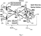
- FIG. 1 depicts various nodes and interfaces which are involved in an LCLS call.
- the "active" User Plane path 100 is for a call between two UEs 102 and 104 wherein local switching is provided between two BTS's, 106 and 108, while the "inactive" User Plane path 109, i.e. the two Abis-links, the two A-links and the links within the Core Network, are not carrying traffic and are therefore marked with dotted lines.
- the Control Plane paths 110 are also illustrated in Figure 1 .
- the radio access network part RAN 117 and the core network part CN 116 are illustrated in figure 1 .
- the radio access network RAN 117 in the embodiment in figure 1 comprises the BCS/BSS 114 and the two BTS's 106 and 108.
- the BSC/BSS 114 has the capability to perform local call switching, however other BSC/BSSs may not have such a capability.
- Various elements in the core network 116 are also shown including the originating MSC (oMSC)118, an intermediate MSC (iMSC) 120 and terminating MSC (tMSC) 122 in the signaling/control plane and various MGWs 124 in the data/control plane.
- LCLS is typically attempted to be instantiated during the call establishment phase in a radiocommunication system.
- negotiation for support of LCLS is performed within the core network (CN) and requests to correlate and connect the originating and terminating terminals (a.k.a. call legs) are made to the BSS when LCLS is successfully negotiated.
- Interaction with existing supplementary services, lawful intercept and handover are supported.
- this may require a break of an existing, locally switched call where the voice data on the user plane is routed via the core network.
- a call is locally switched through the BSS and an inter-system handover occurs to, e.g., an UMTS/LTE RAT, or an inter-BSS handover within the same RAT occurs to a BSS that does not support the LCLS feature
- an inter-system handover occurs to, e.g., an UMTS/LTE RAT, or an inter-BSS handover within the same RAT occurs to a BSS that does not support the LCLS feature
- the locally switched call is broken and normal core network switched user plane is resumed.
- UE-1 which has an ongoing call that is locally switched in the system of Figure 1
- a target BSS not shown in Figure 1
- a target RNS which does not support the LCLS feature.
- the anchor MSC sends a message to the BSS 114 (or BSC) controlling the call leg of the stationary mobile station 104 (UE-2, i.e., the mobile station that is not subject to a handover), requesting the BSS 114 to start sending user plane data UL to the core network in addition to the locally switched user plane data sent between UE-1 102 and UE-2 104.
- the user plane data from UE-2 104 is transmitted to the target BSS (or, respectively, target RNS), where it eventually will be received by UE-1 102 (when UE-1 102 has moved to the target BSS (respectively target RNS) once the handover is successfully completed).
- 3GPP Technical Specification 23.284 specifies that the BSS controlling the call leg of the stationary mobile station (UE-2, the mobile station that is not subject to a handover) at the reception of the above message from the MSC also shall be prepared to receive user plane data DL from the Core Network originating from UE-1 when the mobile station eventually has moved to the target BSS (respectively to the target RNS).
- this BSS has to autonomously, i.e. without any explicit assistance from the CN, switch the incoming user plane data path between the locally switched connection and the Core Network switched path, when user plane data from the Core Network is detected in the BSS.
- The3GPP specification referred to earlier also provides an alternative in case the in-band switch in the BSS based on the detection of the valid user plane, as described above, cannot be implemented in the BSS or will not work due to e.g. interoperability problems.
- a Clear Command message sent from the anchor MSC (triggered by a Handover Complete message received from the target BSS (or by a Relocation Complete message received from the target RNS on the Iu interface) at the successful completion of the handover procedure) to the old serving BSS of the handed over mobile station (UE-1) will break local switching and resume normal user plane switching through the Core Network from both ends.
- the BSS controlling the call leg of the stationary mobile station (UE-2, the mobile station which is not subject to a handover) will no longer use the locally switched user plane path as that path has been broken and thus receive the user plane addressed to UE-2 from the CN.
- the usage of the Clear Command message in the BSS for the purpose of triggering the switch of the user plane data path towards UE-2 104 will cause a longer break in the speech flow between the two parties compared to the same handover scenario in the legacy network (without any impact of the LCLS feature).
- the change of the target MGW user data path from one-way to both-way is triggered already at the reception of the Handover Detect message (respectively the Relocation Detect message received on the Iu interface) in the target MSC, giving the network the possibility to transmit user data from the handed over mobile station to the other end as soon as the mobile station has completed the handover.
- the time lag between the Handover Detect message and the Handover Complete message (or between the Relocation Detect message and the Relocation Complete message) has, in live networks, been measured from 200 ms up to 600 ms.
- the core network can assist in switching the user plane path for a call using LCLS which is being handed over.
- the target BSS or target RNS
- the target BSS will send the Handover Detect message (respectively Relocation Detect message) to its serving MSC.
- This Handover Detect message per se, is a legacy part of the inter-BSS handover and inter-system handover to UMTS procedures, see for example, 3GPP TS 44.018, 3GPP TS 48.008, 3GPP TS 23.205 and 3GPP TS 23.009.
- the reception of the Handover Detect message in the MSC will trigger the sending of a new control message, or an enhanced or modified version of a legacy control message, to the BSS serving the call leg of the other (stationary) mobile station (UE-2).
- the BSS Upon reception of the new control message, or the enhanced or modified version of a legacy control message, the BSS will switch the user plane data path from the locally switched connection to the Core Network switched path. As a result the user plane data is now transmitted from UE-1 102 through the Core Network to the BSS where it is further sent to UE-2 104.
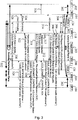
- FIG. 2 shows an exemplary signaling sequence for an embodiment wherein an inter-BSS handover breaks LCLS, and where the call leg belonging to UE-1 is handed over from the serving BSS-1 to the target BSS.
- BSS-1 is the same as BSS-2 when LCLS is established for the call, i.e., local call switching is being performed prior to the handover as indicated by arrows 200.
- a Handover Required message is sent from BSS-1 114 requesting an inter-BSS handover for UE-1 102.
- the Serving BSS-1 114 shall continue to forward the user plane data locally from UE-1 102 to UE-2 104 as long as UE-1 is served by BSS-1.
- the Anchor MSC-1 server sends the Handover Request message, as shown in step/signal 204, to the Target BSS 203 with the LCLS-Connection-Status-Control IE indicating "Connect" to through-connect the local call.
- the Target BSS 203 returns the Handover Request Acknowledge message 206 indicating that the call is not possible to be locally switched since, e.g., Target BSS 203 does not have the LCLS capability.
- the far end MSC-2 server 208 After receiving a message 210 from the anchor MSC 118 regarding LCLS disconnection, the far end MSC-2 server 208 requests the BSS-2 114 to start sending user plane data UL with the LCLS-Connect-Control message 212 and the LCLS-Connection-Status-Control Information Element (IE) indicating "BicastAtHandover". This triggers BSS-2 114 to bi-cast user plane data from UE-2 UL to the Core Network (MGW-2 124) in addition to the locally switched user plane data sent between UE-1 102 and UE-2 104. In the Core Network the user plane data is transmitted to the Target BSS 203 where it eventually will be received by UE-1 102 (when UE-1 102 has moved to the Target BSS 203). Message 212 is acknowledged via message 213.
- IE LCLS-Connection-Status-Control Information Element
- the Anchor MSC-1 118 server sends the BSSMAP Handover Command message 214 to the Serving BSS-1 114 which will trigger the BSS to send the Handover Command message 216 to UE-1 102.
- the Handover Detect message 218 is sent to the Anchor MSC-1 118.
- the Handover Detect message 218 can serve as a trigger for the user plane data path switch in the BSS.
- the Anchor MSC-1 server 118 upon reception of the Handover Detect message 218, the Anchor MSC-1 server 118 sends an LCLS status change message 220 re-using the LCLS-Status-Update message but with a new value in the LCLS-Status-Change-Request IE to the succeeding MSC server 208.
- the far end MSC-2 208 server requests BSS-2 114, via message 222, to switch Down Link (DL) user plane data path on purpose to start receiving user plane data from the Core Network 116 originating from UE-1 102.
- DL Down Link
- the message 222 does not explicitly request BSS-2 (and BSS-1) to break local switching, i.e. BSS-1/BSS-2 may continue to send user plane data locally.
- the break of local switching is initiated at reception of the Clear Command message in the old serving BSS-1, i.e., signal 226 described below.
- MSC-2 server 208 requests BSS-2 114 to break local switching and to start receiving user plane data DL from the Core Network originating from UE-1, i.e. the message 222 will stop BSS-1 and BSS-2 from sending user plane data locally between UE-1 and UE-2. Normal Core Network switched user plane is now resumed at both ends.
- the message 222 sent from the MSC-2 server 208 to BSS-2 114 could, for example, be a completely new message or a re-use of the existing LCLS-Connect-Control message with a new value in the LCLS-Connection-Status-Control IE
- the Target-BSS 203 indicates to the MSC-1 server 118 in the LCLS-BSS-Status IE that the call is not possible to be locally switched.
- the MSC-1 server 118 requests the old serving BSS-1 114 to clear the old call leg via Clear Command message 226.
- the Clear Command message will also break the local switching, i.e. sending of user plane data locally between UE-1 and UE-2 is now stopped.
- the release of local switching can already be done at the reception of the new control message 222 in BSS-2.
- the Serving BSS-2 114 informs the MSC-2 server 208 that LCLS is broken via LCLS-Notification message 228. Clearing of the old call leg in the Serving BSS-1 is completed as indicated by message 230 and the Anchor MSC-1 server 118 informs succeeding Core Network nodes that LCLS is finally disconnected via message 232. At this time, the normally switched user plane is established between UE -1 102 and UE-2 104, as indicated by arrows 234.
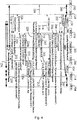
- Similar signaling/steps can be used according to embodiments and examples for performing an inter-system handover which terminates local switching, e.g., to a UMTS RAT, an example of which is provided as Figure 3 .
- a UMTS RAT an example of which is provided as Figure 3 .
- the same node numbering is used in Figure 3 to reference the similar nodes.
- the target node may be labeled as an RNS rather than a BSS in this example.
- inter-system handovers are not limited to UMTS RATs, but can be performed between any desired RATs, e.g., toward LTE RATs, etc.
- the nodes illustrated and discussed below with respect to Figure 3 as BSSs, MSCs, MGWs and RNSs can more generally be referred to as communication nodes and may be implemented differently in other RATs, e.g., LTE.
- one or more of the nodes illustrated in Figure 3 and discussed below can, instead, be an eNodeB or a node in an Evolved Packet Core (EPC), or any other communication node which performs the same or similar functions to those illustrated in Figure 3 .
- EPC Evolved Packet Core
- UE-1 102 and UE-2 104 are connected via a locally switched call using the same BSS 114 as indicated by arrows 302. Then, a Handover Required message 304 is sent from BSS-1 114 requesting an inter-System handover for UE-1 102.
- the Serving BSS-1 114 shall continue to forward the user plane data locally from UE-1 102 to UE-2 1-4 as long as UE-1 102 is served by BSS-1 114.
- the Anchor MSC-1 server 118 sends the Relocation Request message 306 to the Target RNS, and the target RNS returns the Relocation Request Acknowledge message 308.
- the far end MSC-2 server 208 Upon being informed of the change in LCLS status via message 310, the far end MSC-2 server 208 requests the BSS-2 114 to start sending user plane data UL with the LCLS-Connect-Control message 312 and the LCLS-Connection-Status-Control IE indicating "BicastAtHandover".
- Message 312 can be acknowledged by BSS-2 114 via message 313.
- Receipt of message 312 triggers BSS-2 114 to bi-cast user plane data from UE-2 UL to the Core Network 116 (e.g., MGW-2 124) in addition to the locally switched user plane data sent between UE-1 102 and UE-2 104.
- the Core Network 116 the user plane data is transmitted to the Target RNS where it eventually will be received by UE-1 102 (when UE-1 102 has moved to the Target RNS).
- the Anchor MSC-1 118 server sends the BSSMAP Handover Command message 314 to the Serving BSS-1 114, which will trigger the BSS 114 to send the Handover Command message 316 to UE-1 102.
- the Relocation Detect message 317 is sent to the Anchor MSC-1 118.
- the Relocation Detect message 317 is used as a trigger for the user plane data path switch in the BSS 114.
- the Anchor MSC-1 118 server upon the reception of the Relocation Detect message 317, the Anchor MSC-1 118 server according to an embodiment sends a LCLS status change message 318 re-using the LCLS-Status-Update message but with a new value in the LCLS-Status-Change-Request IE to the succeeding MSC server 208.
- the far end MSC-2 server 208 requests BSS-2 114, via message 320, to switch DL user plane data path on purpose to start receiving user plane data from the Core Network 116 which originates from UE-1 102.
- the message 320 does not explicitly request BSS-2 114 (and BSS-1 114) to break local switching, i.e. BSS-1/BSS-2 may continue to send user plane data locally.
- the break of local switching is initiated at reception of the Clear Command message in the old serving BSS-1 114, as described below.
- MSC-2 server 208 requests BSS-2 114 to break local switching and to start receiving user plane data DL from the Core Network 116 originating from UE-1 102, i.e. the message 320 will stop BSS-1 114 and BSS-2 114 from sending user plane data locally between UE-1 102 and UE-2 104. Normal Core Network switched user plane is now resumed at both ends.
- the message 320 sent from the MSC-2 server 208 to BSS-2 114 could be a completely new message or a re-use of the existing LCLS-Connect-Control message with a new value in the LCLS-Connection-Status-Control IE.
- the Target-RNS indicates to the MSC-1 server 118 in the LCLS-BSS-Status IE that the call is not possible to be locally switched.
- the MSC-1 server 118 requests the old serving BSS-1 114 to clear the old call leg via the Clear Command message 324.
- the Clear Command message will also break the local switching, i.e. sending of user plane data locally between UE-1 and UE-2 is now stopped.
- the release of local switching can already be done at the reception of the new control message 320 in BSS-2, as described above.'
- the Serving BSS-2 114 informs the MSC-2 server 208 that LCLS is broken via LCLS-Notification message 326. Clearing of the old call leg in the Serving BSS-1 113 is completed, as indicated by message 328.
- the Anchor MSC-1 server 118 informs succeeding Core Network nodes that LCLS is finally disconnected via message 330 and then data flows via the normally switched user plane 332 after the handover.
- the Handover Detect message as a trigger for switching the DL user plane data path in the serving BSS (or other node) for the stationary mobile station (UE-2) during an inter-system handover or an inter-node handover to a node which does not supporting the LCLS feature, the break in the speech path between the mobile station (UE-1) now located in the target cell and the stationary mobile station (UE-2) will be minimized.
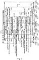
- Figures 4 and 5 illustrate other embodiments and examples of the present method where an inter-BSS ( Figure 4 ) or an inter-RAT ( Figure 5 ) handover occurs where the LCLS connection is terminated. Both figure 4 and 5 contain some minor modifications to embodiments and examples illustrated in figures 2 and 3 . In order to avoid repetition, only the additional signals in these embodiments and examples will be explained, since the remainin signaling in figures 4 and 5 is identical to the embodiments in figures 2 and 3 .
- BSS-2 transmits a LCLS_CONNECT_CONTROL Ack message 222a back to the target MSC-1 208 informing the target MSC-2 208 that the call connection between the first and second user equipments UE-1 102 and UE-2 104 is locally switched with the LCLS configuration requested by the anchor MSC-1 118 in the LCLS-Status-Change-Request message 220, Thereafter, the anchor MSC-1 118 is the informed of the completion of the switching of the user plane path between the first and second user equipments UE-1 102 and UE-2 104 by transmitting an LCLS-Status-Change-Request Ack message 220a from the target MSC-2 208 to the anchor MSC-1 118.
- This message informs the MSC-1 118 that disconnection of the locally switched call connection between UE-1 102 and UE-2 104 is prepared and that the request for change of the locally switched call connection between the two user equipments UE-1 102 and UE-2 104 has been accepted.
- the signals LCLS_CONNECT_CONTROL Ack message 320a and an LCLS-Status-Change-Request Ack message 318a are analogous to signals with reference numbers 222a and 220a mentioned in the previous paragraph and will thus not be explained again.
- the foregoing methods and signaling schemes can be embodied in nodes or structures which are configured to perform the steps described in the above embodiments and examples.
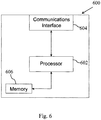
- An exemplary BSS, eNodeB, MSC or other node 600 described above is generically illustrated in Figure 6 .
- the node 600 can include a processor 602 connected to one or more communication interfaces 604.
- the processor 602 is configured to analyze and process signals received from the communications interface(s) 604 and to transmit messages or signals using the communications interface, e.g., as described above with respect to Figures 2 , 3 , 4 and 5 .
- the node 600 includes air interface capability, e.g., if node 600 is or includes base station functionality, then the node 600 includes one or more antennas (not shown) connected to processor 600 via a transceiver.
- the processor 600 may also be connected to one or more memory device 606 in which software code or program instructions can be stored for execution by the processor 600 to, for example, generate the messages described above.
Landscapes
- Engineering & Computer Science (AREA)
- Computer Networks & Wireless Communication (AREA)
- Signal Processing (AREA)
- Mobile Radio Communication Systems (AREA)
Claims (10)
- Procédé dans un noeud de réseau fédérateur (118) de gestion de connexions d'appel localement commutées dans un réseau de communication sans fil, comprenant les étapes consistant à :- recevoir un premier message (218, 317) indiquant qu'un premier équipement d'utilisateur (102) connecté via la connexion d'appel localement commutée a été détecté dans un sous-système de station de base cible, BSS (203) ;- transmettre, déclenché par le premier message (218, 317), une demande de changement de statut de commutation locale d'appel local, LCLS-Status-Change-Request (220, 318) demandant un changement de statut de la connexion d'appel localement commutée vers un second équipement d'utilisateur (104), dans lequel le message de LCLS-Status-Change-Request comprend une valeur dans son élément d'information, IE, la valeur étant « Indiquer des données DL après transfert », indiquant une réception des données de plan utilisateur de liaison descendante issues du premier équipement d'utilisateur (102) au niveau du second équipement d'utilisateur (104) via un chemin commuté de réseau fédérateur (109), de telle sorte qu'un chemin de données de plan utilisateur (100) à partir du premier équipement d'utilisateur (102) vers le second équipement d'utilisateur (104) est commuté vers le chemin de réseau fédérateur (109) ;- recevoir, au niveau du noeud de réseau fédérateur (118) à partir du BSS cible (203), un quatrième message (224, 322) indiquant que le premier équipement d'utilisateur (102) a terminé le transfert et que la connexion d'appel entre le premier équipement d'utilisateur (102) transféré et le second équipement d'utilisateur (104) ne peut être localement commutée ;- transmettre vers un sous-système de station de base source (114), en réponse au quatrième message (224, 322), un cinquième message (226, 324) ordonnant la suppression de la connexion d'appel localement commutée entre le premier équipement d'utilisateur (102) et le second équipement d'utilisateur (104), après que le transfert du premier équipement d'utilisateur (102) est terminé.
- Procédé selon la revendication 1, comprenant en outre l'étape de réception, au niveau du noeud de réseau fédérateur (118), d'un troisième message (220a, 318a) en réponse à la LCLS-Status-Change-Request (220, 318), indiquant qu'une commutation du chemin de données de plan utilisateur (100) vers le chemin de réseau fédérateur (109) a été terminée.
- Procédé selon l'une quelconque des revendications 1 à 2, dans lequel le premier message comprend un message, HO detect, de détection de transfert (218).
- Procédé selon l'une des revendications 1 à 2, dans lequel le premier message comprend un message de détection de relocalisation (317).
- Procédé selon l'une des revendications 1 à 4, dans lequel le quatrième message comprend un message, HO Complete, de transfert terminé (224).
- Procédé selon l'une des revendications 1 à 4, dans lequel le quatrième message comprend un message de relocalisation terminée (322).
- Procédé selon l'une des revendications 1 à 6, dans lequel le cinquième message comprend un message de commande de suppression (226, 324).
- Procédé selon l'une des revendications 1 à 7, dans lequel le noeud de réseau fédérateur (118) comprend un centre de commutation mobile (MSC).
- Procédé selon l'une des revendications 1 à 8, dans lequel la connexion d'appel localement commutée comprend une connexion de données ou vocale entre deux équipements d'utilisateur servie par au moins un noeud de réseau dans lequel la connexion d'appel est localement commutée dans un noeud de réseau supplémentaire contrôlant l'au moins un noeud de réseau.
- Noeud de réseau fédérateur (600) conçu pour un réseau de communication sans fil, comprenant :- une interface de communication (604) conçue pour une réception et une transmission de données et d'informations de contrôle dans le réseau de communication sans fil,- un processeur (602) configuré pour analyser et traiter des signaux reçus à partir de l'interface de communication (604), les signaux comprenant un premier message (218, 317) indiquant qu'un premier équipement d'utilisateur (102) connecté via une connexion d'appel localement commutée a été détecté dans un sous-système de station de base cible (203) et un quatrième message (224, 322)
indiquant que le premier équipement d'utilisateur (102) a terminé le transfert vers le sous-système de station de base cible (203),
le processeur (602) étant en outre configuré pour générer un cinquième message (226, 324) en réponse au quatrième message (224, 322) reçu depuis l'interface de communication (604), le cinquième (226, 324) message ordonnant la suppression de la connexion d'appel localement commutée entre le premier équipement d'utilisateur (102) et le second équipement d'utilisateur (104) après que le premier équipement d'utilisateur (102) a été transféré avec succès vers le sous-système de station de base cible (203)
et pour transmettre le cinquième message (226, 324) vers un sous-système de station de base source (114) via l'interface de communication (604) ;- un dispositif de mémoire (606) pour stocker un code de logiciel conçu pour générer des messages transmis par le processeur (602) via le réseau de communication sans fil,caractérisé en ce que
le processeur (602) est en outre configuré pour générer une demande de changement de statut de commutation locale d'appel local, LCLS-Status-Change-Request (220, 318) en réponse au premier message (218, 317) reçu et pour transmettre la LCLS-Status-Change-Request (220, 318) via l'interface de communication (604) demandant un changement de statut de la connexion localement commutée vers le second équipement d'utilisateur (104), dans lequel le message de LCLS-Status-Change-Request comprend une valeur dans son élément d'information, IE, la valeur étant « Indiquer des données DL après transfert », indiquant une réception de données de plan utilisateur de liaison descendante issues du premier équipement d'utilisateur (102) au niveau du second équipement d'utilisateur (104) via un chemin commuté de réseau fédérateur (109), de telle sorte qu'un chemin de données de plan utilisateur (100) à partir du premier équipement d'utilisateur (102) vers le second équipement d'utilisateur (104) est commuté vers le chemin de réseau fédérateur (109) afin de recevoir des données de plan utilisateur issues du premier équipement d'utilisateur (102) via le chemin de réseau fédérateur (109).
Applications Claiming Priority (2)
| Application Number | Priority Date | Filing Date | Title |
|---|---|---|---|
| US201161449205P | 2011-03-04 | 2011-03-04 | |
| PCT/SE2012/050218 WO2012121644A1 (fr) | 2011-03-04 | 2012-02-27 | Commutation locale d'appel local lors d'un transfert intercellulaire |
Publications (2)
| Publication Number | Publication Date |
|---|---|
| EP2681964A1 EP2681964A1 (fr) | 2014-01-08 |
| EP2681964B1 true EP2681964B1 (fr) | 2017-10-25 |
Family
ID=45955075
Family Applications (1)
| Application Number | Title | Priority Date | Filing Date |
|---|---|---|---|
| EP12714412.9A Active EP2681964B1 (fr) | 2011-03-04 | 2012-02-27 | Commutation locale d'appel local lors d'un transfert intercellulaire |
Country Status (8)
| Country | Link |
|---|---|
| US (2) | US8712419B2 (fr) |
| EP (1) | EP2681964B1 (fr) |
| JP (2) | JP2014508479A (fr) |
| CN (1) | CN103404220B (fr) |
| DK (1) | DK2681964T3 (fr) |
| ES (1) | ES2657617T3 (fr) |
| WO (1) | WO2012121644A1 (fr) |
| ZA (1) | ZA201304738B (fr) |
Families Citing this family (6)
| Publication number | Priority date | Publication date | Assignee | Title |
|---|---|---|---|---|
| US8634838B2 (en) * | 2009-08-14 | 2014-01-21 | Telefonaktiebolaget Lm Ericsson (Publ) | Connection set-up between two terminals |
| EP2681964B1 (fr) * | 2011-03-04 | 2017-10-25 | Telefonaktiebolaget LM Ericsson (publ) | Commutation locale d'appel local lors d'un transfert intercellulaire |
| CN104125612B (zh) * | 2013-04-28 | 2019-09-24 | 中兴通讯股份有限公司 | 非连续接收周期同步方法,系统和设备 |
| WO2017003418A1 (fr) * | 2015-06-29 | 2017-01-05 | Telefonaktiebolaget Lm Ericsson (Publ) | Procédés et appareils permettant de gérer un trafic de données dans un nœud radio ayant une pile de protocoles divisée |
| CN110710261B (zh) * | 2018-01-19 | 2022-05-20 | Oppo广东移动通信有限公司 | 切换处理方法、网络设备、ue及计算机存储介质 |
| US20230108725A1 (en) * | 2020-03-30 | 2023-04-06 | Lenovo (Beijing) Ltd. | Method and apparatus for data transmission |
Family Cites Families (15)
| Publication number | Priority date | Publication date | Assignee | Title |
|---|---|---|---|---|
| JPH08172659A (ja) * | 1994-12-19 | 1996-07-02 | Nec Corp | 移動体通信方式 |
| US5734699A (en) * | 1995-05-04 | 1998-03-31 | Interwave Communications International, Ltd. | Cellular private branch exchanges |
| FI108269B (fi) * | 1999-02-26 | 2001-12-14 | Nokia Corp | Menetelmä luottamusrajan määrittämiseksi tietoliikennejärjestelmässä |
| US7843878B2 (en) * | 2000-12-04 | 2010-11-30 | Ericsson Ab | Method and apparatus to control handoff between different wireless systems |
| US20060229054A1 (en) * | 2005-04-07 | 2006-10-12 | Esa Erola | Help desk connect |
| CN101185299A (zh) * | 2005-05-27 | 2008-05-21 | 艾利森电话股份有限公司 | 无线电接入网中的本地交换 |
| EP2059087A1 (fr) * | 2007-11-06 | 2009-05-13 | Nokia Siemens Networks S.p.A. | Procédé pour établir des appels à commutation de circuits dans un réseau radio mobile et réseau radio mobile correspondant |
| JP2010098444A (ja) * | 2008-10-15 | 2010-04-30 | Ntt Docomo Inc | 交換機及び通信制御方法 |
| WO2010073098A1 (fr) * | 2008-12-23 | 2010-07-01 | Telefonaktiebolaget Lm Ericsson (Publ) | Routage de transfert dans des solutions cs sur lte via gan |
| WO2010127717A1 (fr) * | 2009-05-08 | 2010-11-11 | Telefonaktiebolaget L M Ericsson (Publ) | Commutation locale |
| EP2273820A1 (fr) * | 2009-06-30 | 2011-01-12 | Panasonic Corporation | Transfert inter-VPLMN via un noeud de proxy de transfert |
| CN101998666B (zh) * | 2009-08-12 | 2014-09-10 | 中兴通讯股份有限公司 | 一种本地呼叫本地交换的实现方法 |
| US8634838B2 (en) * | 2009-08-14 | 2014-01-21 | Telefonaktiebolaget Lm Ericsson (Publ) | Connection set-up between two terminals |
| CN101754416B (zh) * | 2009-12-31 | 2012-01-25 | 华为技术有限公司 | 局间建立、解除本地交换的方法和移动交换中心 |
| EP2681964B1 (fr) * | 2011-03-04 | 2017-10-25 | Telefonaktiebolaget LM Ericsson (publ) | Commutation locale d'appel local lors d'un transfert intercellulaire |
-
2012
- 2012-02-27 EP EP12714412.9A patent/EP2681964B1/fr active Active
- 2012-02-27 US US13/497,930 patent/US8712419B2/en active Active
- 2012-02-27 CN CN201280008939.1A patent/CN103404220B/zh active Active
- 2012-02-27 WO PCT/SE2012/050218 patent/WO2012121644A1/fr active Application Filing
- 2012-02-27 DK DK12714412.9T patent/DK2681964T3/en active
- 2012-02-27 ES ES12714412.9T patent/ES2657617T3/es active Active
- 2012-02-27 JP JP2013556580A patent/JP2014508479A/ja active Pending
-
2013
- 2013-06-25 ZA ZA2013/04738A patent/ZA201304738B/en unknown
-
2014
- 2014-03-26 US US14/225,534 patent/US9326193B2/en active Active
-
2017
- 2017-01-18 JP JP2017006962A patent/JP6386596B2/ja active Active
Non-Patent Citations (1)
| Title |
|---|
| None * |
Also Published As
| Publication number | Publication date |
|---|---|
| CN103404220A (zh) | 2013-11-20 |
| JP6386596B2 (ja) | 2018-09-05 |
| WO2012121644A1 (fr) | 2012-09-13 |
| US8712419B2 (en) | 2014-04-29 |
| ES2657617T3 (es) | 2018-03-06 |
| EP2681964A1 (fr) | 2014-01-08 |
| DK2681964T3 (en) | 2018-01-08 |
| JP2017108420A (ja) | 2017-06-15 |
| CN103404220B (zh) | 2019-04-12 |
| US20140235250A1 (en) | 2014-08-21 |
| JP2014508479A (ja) | 2014-04-03 |
| US9326193B2 (en) | 2016-04-26 |
| ZA201304738B (en) | 2014-09-25 |
| US20120225656A1 (en) | 2012-09-06 |
Similar Documents
| Publication | Publication Date | Title |
|---|---|---|
| US11665599B2 (en) | Light-weight RRC connection setup in multi-rat network | |
| KR101320984B1 (ko) | 핸드오버를 위한 방법 및 장치 | |
| US9578571B2 (en) | Paging for circuit switched fallback (CSFB) in long term evolution (LTE) connected mode | |
| EP2521395B1 (fr) | Procédé de gestion d'un transfert inter-RAT dans un système de communication sans fil | |
| JP6386596B2 (ja) | ハンドオーバ時におけるローカル呼ローカル交換 | |
| US9516533B2 (en) | Method for reporting radio link failure information | |
| EP2795965B1 (fr) | Procédé et appareil de détection de la cause d'une défaillance de liaison radio ou d'un échec de transfert intercellulaire | |
| EP2248355A1 (fr) | Procédé amélioré et agencement dans un système de télécommunications | |
| US20180176986A1 (en) | Circuit switched fallback method and apparatus | |
| US20160080992A1 (en) | Method of Inter-RAT Bearer Change for 3GPP System | |
| JP5732467B2 (ja) | 移動側着信手続きの制御方法、端末装置、ネットワークノード装置、方法およびプログラム | |
| KR20230009939A (ko) | 마스터 셀 그룹 실패의 이벤트에서의 통신 관리 | |
| CN108024300B (zh) | 一种降低csfb时延的方法、装置及系统 | |
| Ying et al. | Forward handover for voice call continuity |
Legal Events
| Date | Code | Title | Description |
|---|---|---|---|
| PUAI | Public reference made under article 153(3) epc to a published international application that has entered the european phase |
Free format text: ORIGINAL CODE: 0009012 |
|
| 17P | Request for examination filed |
Effective date: 20130620 |
|
| AK | Designated contracting states |
Kind code of ref document: A1 Designated state(s): AL AT BE BG CH CY CZ DE DK EE ES FI FR GB GR HR HU IE IS IT LI LT LU LV MC MK MT NL NO PL PT RO RS SE SI SK SM TR |
|
| DAX | Request for extension of the european patent (deleted) | ||
| 17Q | First examination report despatched |
Effective date: 20160830 |
|
| REG | Reference to a national code |
Ref country code: DE Ref legal event code: R079 Ref document number: 602012038899 Country of ref document: DE Free format text: PREVIOUS MAIN CLASS: H04W0076040000 Ipc: H04W0036000000 |
|
| GRAP | Despatch of communication of intention to grant a patent |
Free format text: ORIGINAL CODE: EPIDOSNIGR1 |
|
| RIC1 | Information provided on ipc code assigned before grant |
Ipc: H04W 36/10 20090101ALN20170516BHEP Ipc: H04W 36/00 20090101AFI20170516BHEP |
|
| INTG | Intention to grant announced |
Effective date: 20170612 |
|
| GRAS | Grant fee paid |
Free format text: ORIGINAL CODE: EPIDOSNIGR3 |
|
| GRAA | (expected) grant |
Free format text: ORIGINAL CODE: 0009210 |
|
| AK | Designated contracting states |
Kind code of ref document: B1 Designated state(s): AL AT BE BG CH CY CZ DE DK EE ES FI FR GB GR HR HU IE IS IT LI LT LU LV MC MK MT NL NO PL PT RO RS SE SI SK SM TR |
|
| REG | Reference to a national code |
Ref country code: GB Ref legal event code: FG4D |
|
| REG | Reference to a national code |
Ref country code: CH Ref legal event code: EP |
|
| REG | Reference to a national code |
Ref country code: AT Ref legal event code: REF Ref document number: 940984 Country of ref document: AT Kind code of ref document: T Effective date: 20171115 |
|
| REG | Reference to a national code |
Ref country code: SE Ref legal event code: TRGR |
|
| REG | Reference to a national code |
Ref country code: IE Ref legal event code: FG4D |
|
| REG | Reference to a national code |
Ref country code: DE Ref legal event code: R096 Ref document number: 602012038899 Country of ref document: DE |
|
| REG | Reference to a national code |
Ref country code: DK Ref legal event code: T3 Effective date: 20180103 |
|
| REG | Reference to a national code |
Ref country code: NL Ref legal event code: FP |
|
| REG | Reference to a national code |
Ref country code: FR Ref legal event code: PLFP Year of fee payment: 7 |
|
| REG | Reference to a national code |
Ref country code: ES Ref legal event code: FG2A Ref document number: 2657617 Country of ref document: ES Kind code of ref document: T3 Effective date: 20180306 |
|
| REG | Reference to a national code |
Ref country code: LT Ref legal event code: MG4D |
|
| REG | Reference to a national code |
Ref country code: AT Ref legal event code: MK05 Ref document number: 940984 Country of ref document: AT Kind code of ref document: T Effective date: 20171025 |
|
| PG25 | Lapsed in a contracting state [announced via postgrant information from national office to epo] |
Ref country code: FI Free format text: LAPSE BECAUSE OF FAILURE TO SUBMIT A TRANSLATION OF THE DESCRIPTION OR TO PAY THE FEE WITHIN THE PRESCRIBED TIME-LIMIT Effective date: 20171025 Ref country code: NO Free format text: LAPSE BECAUSE OF FAILURE TO SUBMIT A TRANSLATION OF THE DESCRIPTION OR TO PAY THE FEE WITHIN THE PRESCRIBED TIME-LIMIT Effective date: 20180125 Ref country code: LT Free format text: LAPSE BECAUSE OF FAILURE TO SUBMIT A TRANSLATION OF THE DESCRIPTION OR TO PAY THE FEE WITHIN THE PRESCRIBED TIME-LIMIT Effective date: 20171025 |
|
| PG25 | Lapsed in a contracting state [announced via postgrant information from national office to epo] |
Ref country code: RS Free format text: LAPSE BECAUSE OF FAILURE TO SUBMIT A TRANSLATION OF THE DESCRIPTION OR TO PAY THE FEE WITHIN THE PRESCRIBED TIME-LIMIT Effective date: 20171025 Ref country code: AT Free format text: LAPSE BECAUSE OF FAILURE TO SUBMIT A TRANSLATION OF THE DESCRIPTION OR TO PAY THE FEE WITHIN THE PRESCRIBED TIME-LIMIT Effective date: 20171025 Ref country code: BG Free format text: LAPSE BECAUSE OF FAILURE TO SUBMIT A TRANSLATION OF THE DESCRIPTION OR TO PAY THE FEE WITHIN THE PRESCRIBED TIME-LIMIT Effective date: 20180125 Ref country code: HR Free format text: LAPSE BECAUSE OF FAILURE TO SUBMIT A TRANSLATION OF THE DESCRIPTION OR TO PAY THE FEE WITHIN THE PRESCRIBED TIME-LIMIT Effective date: 20171025 Ref country code: LV Free format text: LAPSE BECAUSE OF FAILURE TO SUBMIT A TRANSLATION OF THE DESCRIPTION OR TO PAY THE FEE WITHIN THE PRESCRIBED TIME-LIMIT Effective date: 20171025 Ref country code: IS Free format text: LAPSE BECAUSE OF FAILURE TO SUBMIT A TRANSLATION OF THE DESCRIPTION OR TO PAY THE FEE WITHIN THE PRESCRIBED TIME-LIMIT Effective date: 20180225 |
|
| REG | Reference to a national code |
Ref country code: GR Ref legal event code: EP Ref document number: 20170403595 Country of ref document: GR Effective date: 20180518 |
|
| REG | Reference to a national code |
Ref country code: DE Ref legal event code: R097 Ref document number: 602012038899 Country of ref document: DE |
|
| PG25 | Lapsed in a contracting state [announced via postgrant information from national office to epo] |
Ref country code: SK Free format text: LAPSE BECAUSE OF FAILURE TO SUBMIT A TRANSLATION OF THE DESCRIPTION OR TO PAY THE FEE WITHIN THE PRESCRIBED TIME-LIMIT Effective date: 20171025 Ref country code: CY Free format text: LAPSE BECAUSE OF FAILURE TO SUBMIT A TRANSLATION OF THE DESCRIPTION OR TO PAY THE FEE WITHIN THE PRESCRIBED TIME-LIMIT Effective date: 20171025 Ref country code: EE Free format text: LAPSE BECAUSE OF FAILURE TO SUBMIT A TRANSLATION OF THE DESCRIPTION OR TO PAY THE FEE WITHIN THE PRESCRIBED TIME-LIMIT Effective date: 20171025 |
|
| PG25 | Lapsed in a contracting state [announced via postgrant information from national office to epo] |
Ref country code: PL Free format text: LAPSE BECAUSE OF FAILURE TO SUBMIT A TRANSLATION OF THE DESCRIPTION OR TO PAY THE FEE WITHIN THE PRESCRIBED TIME-LIMIT Effective date: 20171025 Ref country code: SM Free format text: LAPSE BECAUSE OF FAILURE TO SUBMIT A TRANSLATION OF THE DESCRIPTION OR TO PAY THE FEE WITHIN THE PRESCRIBED TIME-LIMIT Effective date: 20171025 Ref country code: RO Free format text: LAPSE BECAUSE OF FAILURE TO SUBMIT A TRANSLATION OF THE DESCRIPTION OR TO PAY THE FEE WITHIN THE PRESCRIBED TIME-LIMIT Effective date: 20171025 |
|
| PLBE | No opposition filed within time limit |
Free format text: ORIGINAL CODE: 0009261 |
|
| STAA | Information on the status of an ep patent application or granted ep patent |
Free format text: STATUS: NO OPPOSITION FILED WITHIN TIME LIMIT |
|
| REG | Reference to a national code |
Ref country code: CH Ref legal event code: PL |
|
| PG25 | Lapsed in a contracting state [announced via postgrant information from national office to epo] |
Ref country code: MC Free format text: LAPSE BECAUSE OF FAILURE TO SUBMIT A TRANSLATION OF THE DESCRIPTION OR TO PAY THE FEE WITHIN THE PRESCRIBED TIME-LIMIT Effective date: 20171025 |
|
| 26N | No opposition filed |
Effective date: 20180726 |
|
| PG25 | Lapsed in a contracting state [announced via postgrant information from national office to epo] |
Ref country code: LU Free format text: LAPSE BECAUSE OF NON-PAYMENT OF DUE FEES Effective date: 20180227 Ref country code: LI Free format text: LAPSE BECAUSE OF NON-PAYMENT OF DUE FEES Effective date: 20180228 Ref country code: CH Free format text: LAPSE BECAUSE OF NON-PAYMENT OF DUE FEES Effective date: 20180228 Ref country code: SI Free format text: LAPSE BECAUSE OF FAILURE TO SUBMIT A TRANSLATION OF THE DESCRIPTION OR TO PAY THE FEE WITHIN THE PRESCRIBED TIME-LIMIT Effective date: 20171025 |
|
| PG25 | Lapsed in a contracting state [announced via postgrant information from national office to epo] |
Ref country code: MT Free format text: LAPSE BECAUSE OF NON-PAYMENT OF DUE FEES Effective date: 20180227 |
|
| PG25 | Lapsed in a contracting state [announced via postgrant information from national office to epo] |
Ref country code: PT Free format text: LAPSE BECAUSE OF FAILURE TO SUBMIT A TRANSLATION OF THE DESCRIPTION OR TO PAY THE FEE WITHIN THE PRESCRIBED TIME-LIMIT Effective date: 20171025 Ref country code: HU Free format text: LAPSE BECAUSE OF FAILURE TO SUBMIT A TRANSLATION OF THE DESCRIPTION OR TO PAY THE FEE WITHIN THE PRESCRIBED TIME-LIMIT; INVALID AB INITIO Effective date: 20120227 |
|
| PG25 | Lapsed in a contracting state [announced via postgrant information from national office to epo] |
Ref country code: MK Free format text: LAPSE BECAUSE OF NON-PAYMENT OF DUE FEES Effective date: 20171025 |
|
| PG25 | Lapsed in a contracting state [announced via postgrant information from national office to epo] |
Ref country code: AL Free format text: LAPSE BECAUSE OF FAILURE TO SUBMIT A TRANSLATION OF THE DESCRIPTION OR TO PAY THE FEE WITHIN THE PRESCRIBED TIME-LIMIT Effective date: 20171025 |
|
| PGFP | Annual fee paid to national office [announced via postgrant information from national office to epo] |
Ref country code: FR Payment date: 20230223 Year of fee payment: 12 Ref country code: DK Payment date: 20230227 Year of fee payment: 12 |
|
| PGFP | Annual fee paid to national office [announced via postgrant information from national office to epo] |
Ref country code: TR Payment date: 20230215 Year of fee payment: 12 Ref country code: SE Payment date: 20230227 Year of fee payment: 12 Ref country code: IT Payment date: 20230221 Year of fee payment: 12 Ref country code: BE Payment date: 20230227 Year of fee payment: 12 |
|
| PGFP | Annual fee paid to national office [announced via postgrant information from national office to epo] |
Ref country code: GR Payment date: 20240227 Year of fee payment: 13 |
|
| PGFP | Annual fee paid to national office [announced via postgrant information from national office to epo] |
Ref country code: NL Payment date: 20240226 Year of fee payment: 13 Ref country code: IE Payment date: 20240227 Year of fee payment: 13 Ref country code: ES Payment date: 20240301 Year of fee payment: 13 |
|
| PGFP | Annual fee paid to national office [announced via postgrant information from national office to epo] |
Ref country code: DE Payment date: 20240228 Year of fee payment: 13 Ref country code: CZ Payment date: 20240207 Year of fee payment: 13 Ref country code: GB Payment date: 20240227 Year of fee payment: 13 |