EP2680655A1 - Providing control information for multi-carrier uplink transmission - Google Patents
Providing control information for multi-carrier uplink transmission Download PDFInfo
- Publication number
- EP2680655A1 EP2680655A1 EP13186418.3A EP13186418A EP2680655A1 EP 2680655 A1 EP2680655 A1 EP 2680655A1 EP 13186418 A EP13186418 A EP 13186418A EP 2680655 A1 EP2680655 A1 EP 2680655A1
- Authority
- EP
- European Patent Office
- Prior art keywords
- carrier
- wtru
- uplink carrier
- uplink
- power
- Prior art date
- Legal status (The legal status is an assumption and is not a legal conclusion. Google has not performed a legal analysis and makes no representation as to the accuracy of the status listed.)
- Withdrawn
Links
Images


Classifications
-
- H—ELECTRICITY
- H04—ELECTRIC COMMUNICATION TECHNIQUE
- H04L—TRANSMISSION OF DIGITAL INFORMATION, e.g. TELEGRAPHIC COMMUNICATION
- H04L5/00—Arrangements affording multiple use of the transmission path
- H04L5/0001—Arrangements for dividing the transmission path
- H04L5/0003—Two-dimensional division
- H04L5/0005—Time-frequency
- H04L5/0007—Time-frequency the frequencies being orthogonal, e.g. OFDM(A), DMT
-
- H—ELECTRICITY
- H04—ELECTRIC COMMUNICATION TECHNIQUE
- H04W—WIRELESS COMMUNICATION NETWORKS
- H04W72/00—Local resource management
- H04W72/20—Control channels or signalling for resource management
-
- H—ELECTRICITY
- H04—ELECTRIC COMMUNICATION TECHNIQUE
- H04L—TRANSMISSION OF DIGITAL INFORMATION, e.g. TELEGRAPHIC COMMUNICATION
- H04L27/00—Modulated-carrier systems
- H04L27/26—Systems using multi-frequency codes
- H04L27/2601—Multicarrier modulation systems
-
- H—ELECTRICITY
- H04—ELECTRIC COMMUNICATION TECHNIQUE
- H04L—TRANSMISSION OF DIGITAL INFORMATION, e.g. TELEGRAPHIC COMMUNICATION
- H04L5/00—Arrangements affording multiple use of the transmission path
- H04L5/003—Arrangements for allocating sub-channels of the transmission path
- H04L5/0053—Allocation of signaling, i.e. of overhead other than pilot signals
-
- H—ELECTRICITY
- H04—ELECTRIC COMMUNICATION TECHNIQUE
- H04W—WIRELESS COMMUNICATION NETWORKS
- H04W52/00—Power management, e.g. TPC [Transmission Power Control], power saving or power classes
- H04W52/04—TPC
- H04W52/30—TPC using constraints in the total amount of available transmission power
- H04W52/36—TPC using constraints in the total amount of available transmission power with a discrete range or set of values, e.g. step size, ramping or offsets
- H04W52/365—Power headroom reporting
-
- H—ELECTRICITY
- H04—ELECTRIC COMMUNICATION TECHNIQUE
- H04W—WIRELESS COMMUNICATION NETWORKS
- H04W52/00—Power management, e.g. TPC [Transmission Power Control], power saving or power classes
- H04W52/04—TPC
- H04W52/38—TPC being performed in particular situations
-
- H—ELECTRICITY
- H04—ELECTRIC COMMUNICATION TECHNIQUE
- H04W—WIRELESS COMMUNICATION NETWORKS
- H04W72/00—Local resource management
- H04W72/20—Control channels or signalling for resource management
- H04W72/21—Control channels or signalling for resource management in the uplink direction of a wireless link, i.e. towards the network
-
- H—ELECTRICITY
- H04—ELECTRIC COMMUNICATION TECHNIQUE
- H04W—WIRELESS COMMUNICATION NETWORKS
- H04W24/00—Supervisory, monitoring or testing arrangements
- H04W24/10—Scheduling measurement reports ; Arrangements for measurement reports
-
- H—ELECTRICITY
- H04—ELECTRIC COMMUNICATION TECHNIQUE
- H04W—WIRELESS COMMUNICATION NETWORKS
- H04W52/00—Power management, e.g. TPC [Transmission Power Control], power saving or power classes
- H04W52/04—TPC
- H04W52/18—TPC being performed according to specific parameters
- H04W52/28—TPC being performed according to specific parameters using user profile, e.g. mobile speed, priority or network state, e.g. standby, idle or non transmission
- H04W52/286—TPC being performed according to specific parameters using user profile, e.g. mobile speed, priority or network state, e.g. standby, idle or non transmission during data packet transmission, e.g. high speed packet access [HSPA]
Definitions
- This application is related to wireless communications.
- Wireless communication systems keep evolving to meet the needs for providing continuous and faster access to a data network.
- a multi-carrier system that is capable of using multiple carriers for the transmission of data has been proposed.
- the use of multiple carriers is expanding in both cellular and non-cellular wireless systems,
- a multi-carrier system may increase the bandwidth available in a wireless communication system according to a multiple of how many carriers are made available.
- DC-HSDPA dual-cell high speed downlink packet access
- 3GPP third generation partnership project
- UMTS universal mobile telecommunication systems
- each WTRU is assigned an anchor downlink carrier, which carries all dedicated and shared control channels used for high speed downlink shared channel (HS-DSCH), enhanced dedicated channel (E-DCH), and dedicated channel (DCH) operations (e.g., fractional dedicated physical channel (F-DPCH), E-DCH HARQ indicator channel (E-HICH), E-DCH relative grant channel (E-RGCH), E-DCH absolute grant channel (E-AGCH), common pilot channel (CPICH), high speed shared control channel (HS-SCCH), and high speed physical dedicated control channel (HS-PDCCH)).
- the WTRU may be assigned a supplementary downlink carrier, which carries CPICH, HS-SCCH and HS-PDSCH for the WTRU.
- the uplink (UL) transmission remains on a single carrier as in the current systems.
- the HS-DPCCH feedback information is provided on this UL carrier to the Node-B and contains information for each downlink carrier.
- Figure 1 shows the conventional medium access control (MAC) architecture for DC-HSDPA operations.
- the MAC layer architecture of DC-HSDPA includes one hybrid automatic repeat request (HARQ) entity per HS-DSCH transport channel.
- HARQ hybrid automatic repeat request
- the E-DCH is based on a grant mechanism.
- each Node-B has a means to control the level of interference caused by WTRUs by increasing or decreasing the serving grant.
- the serving grant represents the amount of power a WTRU is allowed to use for the E-DCH, which translates to a data rate.
- the amount of grant a WTRU gets is determined by the network based on the system load and the traffic offered. To help the network make suitable decisions, the WTRU provides buffer and power headroom information to the serving Node-B via scheduling information (SI) and happy bit.
- SI scheduling information
- a WTRU may set a happy bit for E-DCH transmissions on each uplink carrier considering aggregate transmission capability of all uplink carriers.
- the happy bit is set for each uplink carrier to "unhappy" if the WTRU is transmitting as much scheduled data on the uplink carrier as allowed by a current serving grant, the WTRU has enough power available on the uplink carrier to transmit at a higher data rate, and total E-DCH buffer status (TEBS) requires more than a pre-configured time period to be transmitted with a current effective data rate aggregated over all uplink carriers.
- TEBS total E-DCH buffer status
- the WTRU may send scheduling information including power headroom as measured on the anchor uplink carrier and/or power headroom as measured on the supplementary uplink carrier. For the power headroom measurements on the supplementary carrier, the WTRU may initiate a short-lived power control loop on the supplementary uplink carrier.
- FIG 1 shows the conventional medium access control (MAC) architecture for DC-HSDPA operations
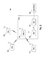
- Figure 2 shows a wireless communication system including a plurality of WTRUs, a Node B, a controlling radio network controller (CRNC), a serving radio network controller (SRNC), and a core network;
- CRNC controlling radio network controller
- SRNC serving radio network controller
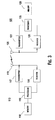
- Figure 3 is a functional block diagram of the WTRU and the Node B of the wireless communication system of Figure 2 ;
- Figure 4 shows an example that a WTRU transmits two uplink carriers to the UTRAN
- FIG. 5 is a functional block diagram wherein two uplink carriers are controlled by transmit power control (TPC) commands transmitted to a WTRU on two downlink carriers;
- TPC transmit power control
- FIGS 6 and 7 are functional block diagrams wherein two uplink carriers are controlled by transmit power control (TPC) commands transmitted to a WTRU on a single downlink carrier;
- TPC transmit power control
- Figure 8 shows an example F-DPCH slot format in accordance with one embodiment
- FIG. 9 is a functional block diagrams wherein transmit power control (TPC) commands are sent in the uplink in a multiple uplink carrier environment;
- TPC transmit power control
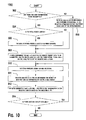
- Figure 10 is a flow diagram of an example process for E-TFC selection and MAC-e or MAC-i PDU generation while utilizing two uplink carriers;
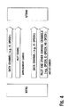
- FIG. 11 shows scheduling information format in accordance with one embodiment.
- the terminology “WTRU” includes but is not limited to a user equipment (UE), a mobile station, a fixed or mobile subscriber unit, a pager, a cellular telephone, a personal digital assistant (PDA), a computer, a machine-to-machine (M2M) device, a sensor, or any other type of device capable of operating in a wireless environment.
- UE user equipment
- PDA personal digital assistant
- M2M machine-to-machine
- Node-B includes but is not limited to a base station, a site controller, an access point (AP), or any other type of interfacing device capable of operating in a wireless environment.
- the network may assign at least one downlink and/or at least one uplink carrier as an anchor downlink carrier and an anchor uplink carrier, respectively.
- the anchor carrier may be defined as the carrier for carrying a specific set of control information for downlink/uplink transmissions. Any carrier that is not assigned as an anchor carrier is a supplementary carrier. Alternatively, the network may not assign an anchor carrier and no priority, preference, or default status may be given to any downlink or uplink carriers.
- anchor carrier and “primary carrier”
- supplementary carrier” and “secondary carrier” will be used interchangeably, respectively.
- the “first carrier” (or “second carrier”) may be either the anchor carrier or the supplementary carrier. For multi-carrier operation more than one supplementary carriers or secondary carriers may exist.
- the embodiments are provided for generating and transmitting control information enabling uplink scheduling for multi-carrier operations.
- the control information may comprise measurements indicative of WTRU power situation, buffer information, measurements indicative of the need of the WTRU for more uplink transmission resources.
- WCDMA wideband code division multiple access
- the embodiments described herein are applicable to multiple uplink carriers as well.
- WCDMA wideband code division multiple access
- LTE long term evolution
- LTE-A long term evolution
- Figure 2 shows a wireless communication system 100 including a plurality of WTRUs 110, a Node B 120, a controlling radio network controller (CRNC) 130, a serving radio network controller (SRNC) 140, and a core network 150.
- the Node B 120 and the CRNC 130 with the SRNC 140 may collectively be referred to as the universal terrestrial radio access network (UTRAN).
- UTRAN universal terrestrial radio access network
- the WTRUs 110 are in communication with the Node B 120, which is in communication with the CRNC 130 and the SRNC 140. Although three WTRUs 110, one Node B 120, one CRNC 130, and one SRNC 140 are shown in Figure 2 , it should be noted that any combination of wireless and wired devices may be included in the wireless communication system 100.
- FIG 3 is a functional block diagram of the WTRU 110 and the Node B 120 of the wireless communication system 100 of Figure 2 .
- the WTRU 110 is in communication with the Node B 120 and both are configured to perform a method of providing control information for multi-carrier uplink transmission.
- the WTRU 110 includes a processor 115, a receiver 116, a transmitter 117, a memory 118, an antenna 119, and other components (not shown) that may be found in a typical WTRU.
- the memory 118 is provided to store software including operating system, application, etc.
- the processor 115 is provided to perform, alone or in association with the software, a method of providing control information for multi-carrier uplink transmission in accordance with embodiments disclosed below.
- the receiver 116 and/or the transmitter 117 are capable of receiving and/or transmitting over multiple carriers. Alternatively, multiple receivers or transmitters may be included in the WTRU 110.
- the receiver 116 and the transmitter 117 are in communication with the processor 115.
- the antenna 119 is in communication with both the receiver 116 and the transmitter 117 to facilitate the transmission and reception of wireless data.
- the Node B 120 includes a processor 125, a receiver 126, a transmitter 127, a memory 128, an antenna 129, and other components (not shown) that may be found in a typical base station.
- the processor 125 is configured to support a method of providing control information for multi-carrier uplink transmission in accordance with embodiments disclosed below.
- the receiver 126 and the transmitter 127 are in communication with the processor 125.
- the receiver 126 and/or the transmitter 127 are capable of receiving and/or transmitting over multiple carriers. Alternatively, multiple receivers or transmitters may be included in the Node B 120.
- the antenna 129 is in communication with both the receiver 126 and the transmitter 127 to facilitate the transmission and reception of wireless data.
- Embodiments for indicating by the WTRU for the need or no need of additional uplink resource for multi-carrier operations are described hereafter.
- the need or no-need of the additional uplink resource is indicated by a single-bit indication called "happy bit" carried on the uplink control channel, (i.e., E-DPCCH).
- a happy bit is a single bit indicating whether or not a WTRU is currently "happy" with its current allowed uplink transmission data rate.
- the happy bit is transmitted by the WTRU every E-DCH transmission and is carried on the E-DPCCH.
- the WTRU reports that it is happy when it has ability to empty its transmission buffer in a certain configured amount of time given the current grant and the number of active HARQ processes.
- the happy bit is set to "unhappy" if the following three criteria are met:
- setting of the happy bit is defined when two uplink carriers are used. With two uplink carriers configured, the happy bit may be sent on each uplink carrier and may take a different value on each uplink carrier.
- the WTRU may use the 3GPP Release 8 or earlier rules to the active uplink carrier.
- the happy bit may be set to "unhappy" for a given carrier when a WTRU is using all its grant on that carrier, has sufficient headroom to support higher data rates on that carrier, and the time it would take in the current state taking both carriers into consideration to empty the buffer is longer than a given threshold.
- the happy bit setting rules may be rewritten as follows.
- the happy bit may be set to "unhappy" if the three following criteria are met:
- the threshold amount of time (e.g., Happy_Bit_Delay_Condition_2TB value) may be signaled by the network.
- the Happy_Bit_Delay_Condition_2TB value may be the same as the conventional Happy_Bit_Delay_Condition value that is used where one transport block, (i.e., one uplink carrier), is transmitted.
- the happy bit on each uplink carrier may be set according to the respective power headroom conditions and individual grants of each uplink carrier. This means that the happy bit may be set to "happy" on one uplink carrier while the happy bit is set to "unhappy” on the other uplink carrier, if, for instance, there is enough power headroom to transmit at a higher data rate on the other uplink carrier, or if the grant on the other uplink carrier is lower.
- the happy bit on one uplink carrier is set according to the combined conditions (grant and power headroom) of both uplink carriers.
- the happy bit may be set to "unhappy" (1) if the WTRU is transmitting as much scheduled data as allowed by the current serving grants on both uplink carriers in E-TFC selection for both uplink carriers, (2) if the WTRU has enough power available to transmit at a higher data rate on any or all of the uplink carriers; or (3) based on the same power offset(s) as the one selected in E-TFC selection (on both uplink carriers) to transmit data in the same TTI as the happy bit, if total E-DCH buffer status (TEBS) would require more than a threshold amount of time, (e.g., Happy_Bit_Delay_Condition ms, or other value), to be transmitted with the current serving grants, taking into account the ratio of active processes to the total number of processes on each carrier.
- a threshold amount of time e.g., Happy_Bit_Delay_Condition ms
- the happy bit on one uplink carrier is set according to the combined conditions of both uplink carriers, the happy bit on the second uplink carrier may be re-interpreted in one or a combination of the following:
- additional information for uplink scheduling may be transmitted via the happy bits by the WTRU.
- the two happy bits may be optioned for different usages.
- one happy bit may be used to indicate overall happiness status of the WTRU in accordance with one of the embodiments disclosed herein, while the other happy bit may carry information totally different.
- the former one is referred to as "a primary happy bit” and the later one is referred to as "a secondary happy bit”.
- the secondary happy bit may be set (to either "0" or "1") depending on a condition that the power headroom of the anchor carrier is larger than the power headroom of the secondary carrier.
- the power headroom may correspond to, or may be equivalent to, one or a combination of the following measurements: DPCCH power (i.e., the carrier with the lowest DPCCH power translates to the carrier with the highest power headroom), uplink power headroom value (per carrier UE power headroom (UPH) value calculated and reported in the SI), or an averaged DPCCH power of each carrier, for example over N slots, where N is a integer that may be predetermined in the WTRU or configured by the network. For example, the number of slots for averaging may be three (3), which is equivalent to the averaged DPCCH used in the NRPM calculation.
- the secondary happy bit may be set (to either "0" or "1") depending on at least one of the conditions that the power headroom of the anchor carrier is larger than the power headroom of the secondary carrier by a configured threshold, (i.e., the power headroom difference is above a threshold), that the power headroom of the anchor carrier is larger than the power headroom of the secondary carrier for a configured or predetermined period of time, optionally by a configured threshold, or that the DPCCH power of the anchor carrier averaged across a number of sub-frames or slots is no larger than that of the secondary carrier (optionally, by a pre-defined or pre-configured threshold).
- a configured threshold i.e., the power headroom difference is above a threshold
- the power headroom of the anchor carrier is larger than the power headroom of the secondary carrier for a configured or predetermined period of time
- a configured threshold optionally by a configured threshold
- the DPCCH power of the anchor carrier averaged across a number of sub-frames or slots is no larger than that of the
- the secondary happy bit may be set (to either "0” or “1") based on comparison results (optionally averaged across multiple sub-frames or slots) that are generated, at each sub-frame, by comparing the DPCCH power of the anchor carrier to that of the secondary carrier.
- the secondary happy bit may be set (to either "0” or “1") based on comparison results (optionally averaged across multiple sub-frames or slots) that are generated, at each sub-frame, by comparing the power headroom of the anchor carrier to that of the secondary carrier.
- the averaging method may be either arithmetic average with truncation or majority vote, or the like.
- the E-TFC selection procedure may select only one carrier for E-DCH transmission in a TTI (that is, only one carrier is E-DCH active and thus transmitting E-DPDCH and E-DPCCH). In this case, only one E-DPCCH (and thus only one happy bit) is transmitted on the E-DCH active carrier and no happy bit is transmitted over the E-DCH inactive carrier.
- the WTRU may transmit a single happy bit on either the anchor carrier or the supplementary carrier. The primary happy bit may be transmitted over the anchor carrier and the secondary happy bit may be transmitted over the supplementary carrier, or vice versa, regardless of the number of active E-DCH carriers.
- the primary happy bit may be transmitted over the anchor carrier and the secondary happy bit may be transmitted over the secondary carrier, or vice versa. If only one carrier is E-DCH active, the primary happy bit may be transmitted on the E-DCH active carrier (regardless of whether or not it is the anchor carrier) and the secondary happy bit may not be transmitted.
- the rules for setting the happy bits may be applied individually to each carrier regardless of the number of transport blocks being transmitted.
- the conventional (3GPP Release 8 or earlier) rules for happy bit may be used on each carrier individually.
- the WTRU may use two different values for the Happy_Bit_Delay_Condition for each uplink carrier as configured by the network: one associated with the anchor uplink carrier and the other associated with the supplementary uplink carrier.
- Embodiments for triggering, and transmitting, WTRU control information (i.e., scheduling information) for multi-carrier operations are described hereafter.
- WTRU control information i.e., scheduling information
- a WTRU is configured with a MAC-is/i
- several triggers are defined to transmit SI.
- Transmission of SI is triggered when a WTRU cannot transmit data at all (due to HARQ processes being not activated, grant being too low, etc.) and the size of the transmit buffer becomes larger than 0; when the serving grant is zero and new higher priority data than what is currently in the transmission buffer arrives (this is used to inform the Node-B that new higher priority data has arrived); when periodic SI is triggered as configured by the network; or when there is a change of E-DCH serving cell and the new serving E-DCH cell is on a different Node-B.
- These mechanisms need to be adapted or changed to function properly in the context of multi-carrier operations, for example DC-HSUPA. The actual changes may depend on the information carried on the SI.
- the scheduling information may be modified such that it provides the UL power headroom measurement for each carrier individually. More specifically, the format of the SI may be expanded to include UPH for the supplementary carrier, as shown in Figure 11 , where UPH A and UPH S , correspond to the ratio of the maximum WTRU transmission power and the corresponding anchor and supplementary DPCCH code power, respectively.
- the WTRU may report one UPH measurement, and the Node-B may infer the UPH of the other carrier based on Node-B internal measurements and parameters, such as a noise rise difference between the carriers and/or the DPCCH signal-to-interference ratio (SIR) target on each carrier.
- SIR DPCCH signal-to-interference ratio
- UPH / P DPCCH ⁇ 1 + P DPCCH ⁇ 2 P max , ix , where P max, tx is the total maximum output power that can be transmitted by the WTRU and P DPCCH1 and P DPCCH2 represent the transmitted code power on DPCCH of carrier 1 and carrier 2, respectively.
- P max, tx may represent the sum of the per-carrier maximum transmission powers.
- the WTRU may report the SI individually in each carrier. For instance, if the SI is sent over the anchor carrier it reports the UPH of the anchor carrier (UPH A ), and if it sent over the supplementary carrier it reports the UPH of the supplementary carrier (UPHs). More specifically, the UPH for the anchor carrier (UPH A ) is the ratio of the maximum WTRU transmission power and the DPCCH code power on the anchor carrier, and the UPH for the supplementary carrier (UPHs) is the ratio of the maximum WTRU transmission power and the DPCCH code power on the supplementary carrier.
- the buffer information fields i.e., TEBS, highest priority logical channel ID (HLID), and highest priority logical channel buffer status (HLBS) of the two SIs may carry common information or may be different. Sending the scheduling information (SI) over the two uplink carriers independently with the common buffer status information would be inefficient. This problem would be overcome by the embodiments disclosed herein.
- SI type A This SI contains the same information fields as the 3GPP Release 8 SI, where the UPH carries the headroom as measured on the anchor carrier.
- the SI type A carries the following fields: UPH of anchor carrier (UPH A ), TEBS, highest priority logical channel buffer status (HLBS), and highest priority logical channel ID (HLID).
- SI type S This SI contains the same information fields as the SI type A but the UPH carries the headroom as measured on the supplementary carrier instead of anchor carrier.
- the SI type S carries the following fields: UPH of supplementary carrier (UPH S ), TEBS, HLBS, and HLID.
- SI type AS This SI contains the same information fields as the SI type A but the UPH carries the headroom of both anchor and supplementary carriers.
- the SI type AS carries the following fields: UPH A , UPH S , TEBS, HLBS, and HLID. Alternatively, the two fields UPH A and UPH S may be carried in one field carrying the combined information. It should be noted that the number of bits assigned to each field may be the same as in the current (3GPP Release 8) SI, or the number of bits may be changed to accommodate the additional information.
- This SI type may also be interpreted as a legacy SI (e.g., Release 8) with an additional field carrying the UPH of the supplementary carrier.
- SI type E This SI contains the same information fields as the SI type A but the UPH carries the headroom of either anchor carrier or supplementary carrier.
- the SI type E carries the following fields: UPH A or UPH S , TEBS, HLBS, HLID, and an additional field to indicate whether the first field corresponds to UPH A or UPH S .
- the SI type E may replace SI type A and SI type S as it carries the same information fields (except for the indication bit).
- SI type R This SI accounts for the fact that the other SI already contains the buffer status information (TEBS, HLBS, HLBS, HLID) such that the space for the buffer status information may be used for other purposes.
- the SI type R may carry UPH A or UPH S , and the spare fields may be used for other purposes.
- the spare fields may be used to indicate the causes of the SI reporting triggering, as an extension of the TEBS for bigger MAC buffer size, for SI type indication as described below, etc.
- the SI type requires more than 18 bits (the size of the 3GPP Release 8 SI)
- a new entry may be defined in the conventional E-DCH transport block size tables or the conventional E-DCH transport block size tables may be modified to support the new SI size.
- the value of the first non-zero entry in the E-DCH transport block size tables may depend on whether or not the WTRU is configured to transmit a specific SI type (e.g., SI type AS).
- the WTRU is not configured to transmit SI type AS
- the value of the first non-zero entry (or the entry for SI stand-alone transmission) for all E-DCH transport block size tables remains 18 bits as in the 3GPP Release 8 E-DCH transport block size tables
- the first non-zero entry (or the entry for SI stand-alone transmission) in the E-DCH transport block size tables may be different, (for example, 23 bits if the number of bits for UPH A and UPH S are both 5 bits as the 3GPP Release 8).
- the SI type containing more than 18 bits may be transmitted only when piggybacked to other data.
- additional SI formats may be defined for the case where some fields of the 3GPP Release 8 SI may not be necessary.
- the 3GPP Release 8 SI includes TEBS, HLBS, HLID and UPH, but it may not be necessary to transmit the HLBS, HLID, and/or TEBS every time if the reason for sending the SI is to convey information about power headroom on the carriers.
- the size of the SI may be maintained less than or equal to 18 bits thus avoiding the need for defining additional transport block size entry or having to define additional E-TFC transport block size tables.
- the remaining bits may be set to pre-defined values or may be defined as spare.
- the WTRU may be configured with an SI format that contains only UPH S , (or both UPH S and UPH A ).
- Other information i.e., TEBS, HLID, and HLBS
- this SI may not be provided, as it is assumed that they have already been provided with the SI on the other uplink carrier, (e.g., anchor carrier). This will allow the WTRU not to duplicate the same information.
- an SI type indication may be provided.
- a new field may be included in the MAC header, or a logical channel ID may be reserved for this purpose.
- the carrier over which the SI is transmitted may carry this information, (e.g., the WTRU transmits SI type S over the supplementary uplink carrier only).
- the LCH-ID 0, i.e., LCH-ID field in the MAC header set to 1111
- LCH-ID 0 followed by a new reserved value of the spare bits after the LCH-ID 0 may be used to indicate the presence of the SI.
- the time when the SI is transmitted or the HARQ process number may also be used to distinguish SI types.
- one or several spare value(s) of the MAC-i header may be used to distinguish the SI types.
- the TEBS field set to '0' along with HLID field or of certain bits of the HLID field set to a value different than '0' may be used to distinguish between different SI types.
- the HLID field is constrained to be set to '0' in case TEBS is set to '0.'
- the use of a value different than '0' for the HLID field when TEBS is set to '0' may be used to indicate a special format of the SI.
- This special format either may not contain the TEBS, HLID, and/or HLBS information, or may contain the TEBS, HLID, and/or HLBS information in additional fields, (e.g., TEBSprime, HLIDprime, HLBSprime).
- the WTRU may be configured by higher layers to only use one specific SI type for transmission on a given UL carrier. This removes the need for additional signaling to indicate the SI type, at the expense of flexibility. For example, SI type A may be transmitted over the anchor carrier and SI type S may be transmitted over the secondary carrier.
- the WTRU may only send SI type A in accordance with the conventional rules. Alternatively, the WTRU may still send SI type S or AS along with SI type A in that case with the UPH S set to zero.
- Embodiments for triggering transmission of control information for enabling uplink scheduling are disclosed. More specifically for HSPA operations, this control information may comprise the scheduling information (SI).
- the triggers may be applicable not only to SI type S and type AS, but also to SI type A (legacy) and SI type E or R. Furthermore, these rules and triggers may be independently applied to both anchor and secondary uplink carriers.
- the rules for triggering transmission of the SI type A may be the same as the conventional rules to transmit the SI in 3GPP Release 8.
- a periodic measurement may be configured by the network where a short-lived power control loop is initiated to measure the headroom on the supplementary carrier, for example when it is de-activated.
- the short-lived DPCCH loop comprises the transmission and reception of uplink DPCCH and downlink DPCCH(s) or F-DPCH(s) for a short duration to establish power control loop and measure the power headroom on the supplementary uplink carrier.
- SI type S or SI type AS may be transmitted over either the anchor uplink carrier or the supplementary uplink carrier once the measurement and the power headroom calculation on the supplementary uplink carrier is complete.
- the WTRU may turn off the DPCCH transmission on the supplementary carrier.
- the WTRU may be configured to wait for a given time before turning off the DPCCH transmission on the supplementary carrier.
- the WTRU may wait for an explicit signal from the network to turn off (or continue) the DPCCH transmission on the supplementary carrier.
- the WTRU may monitor an E-AGCH associated to the supplementary uplink carrier or an HS-SCCH for a specific command regarding the state of the DPCCH transmission on the supplementary uplink carrier.
- the WTRU may stop monitoring the network indication and turn off the DPCCH transmission on the supplementary carrier after a given wait timer has expired.
- the short-lived power control loop itself and/or the power headroom measurement on the supplementary uplink carrier may be triggered by one or a combination of the following events: when UPH A becomes smaller than a threshold, when TEBS becomes larger than a threshold, when the time it would take to empty the transmission buffer given the current grant, HARQ power offset and the ratio of active HARQ processes (on the anchor uplink carrier) is longer than a configured value, when a periodic timer has expired, (i.e., the power headroom measurement and/or the short-lived power control loop is triggered periodically), when SI transmission is triggered on the anchor carrier (for any reason), when the grant on the anchor carrier is zero and data becomes available in the buffer, and/or when periodic SI transmission is triggered on the anchor carrier.
- any of the above triggers necessitating power headroom measurement on the supplementary carrier may be carried out with the short-lived power control loop.
- the supplementary uplink carrier When the supplementary uplink carrier is enabled, (i.e., there is a DPCCH being transmitted on the uplink supplementary carrier), one or more of the following rules may be used, in any order or combination.
- SI type A or alternatively SI type AS, may be transmitted in accordance with the 3GPP Release 8 rules.
- SI type AS may be transmitted in this case based on the 3GPP Release 8 SI triggering rules.
- the network may configure separate and independent cycles for sending SI type A, SI type S, and/or SI type AS.
- SI type A and either of SI type S or SI type AS may be transmitted.
- the network may configure a single periodic SI trigger cycle for transmission of both SI type A and SI type S or alternatively for SI type A and SI type AS.
- the SI type transmitted may alternate in time, according to a known pattern by the WTRU and the network. For instance, this pattern may be pre-defined or based on one or a combination of the connection frame number (CFN), HARQ process, E-DCH radio network temporary identity (E-RNTI) and other configured parameters.
- This scheme may be applied to one or both periodic SI triggers, (i.e., triggers related to T_SING and T_SIG timers).
- the WTRU may be configured to use one or more common timers, (for example, T_SING and/or T_SIG), for transmission of both SI type A and SI type S or alternatively for SI type AS.
- the WTRU may use each common timer for triggering the SI for all uplink carriers.
- one timer or one timer value (either T_SING or T_SIG), may be allowed to be used at a time by all uplink carriers.
- the WTRU may use different timer values under these conditions, but once SI is triggered, the WTRU may reset them all to keep synchronization. Once the timer in use is triggered, both SI type A and S (or alternatively SI type AS) may be generated and reported.
- T_SING may be utilized for the case where none of the carriers has SG allocated for the WTRU
- T_SIG may be used for the case where the WTRU has SG for both carriers.
- the two carriers may still share a common timer or timer value, which may be either T_SING or T_SIG, or alternatively a third timer that may be configured or used differently in either cycle or start timing.
- determining the use of the timers may be based on network configuration of the HARQ processes for the two carriers.
- T_SING may be utilized for the case where all HARQ processes are deactivated by the network on both carriers, and T_SIG may be used for the case where each carrier has at least one activated HARQ process configured.
- the two carriers may share a common timer, which may be either T_SING or T_SIG, or alternatively a third timer that may be configured differently in either cycle or start timing.
- the grant status and HARQ process configuration may be jointly taken into account when deciding the use of the timers. More specifically, the conditions of use of each timer may be as follows:
- T_SING may be used and started in both carriers. If none of the two carries has any HARQ process activated, regardless of the grant status, T_SING may be used and started in both carriers. If one carrier has zero serving grant regardless of its HARQ configuration status, and one carrier has no HARQ process activated regardless of its grant status, T_SING may be used and started. If both carriers have non-zero serving grant and at least one HARQ process is activated on each carrier, T_SIG may be used and started in both carriers.
- T_SIG or T_SING a third timer
- T_STG or T_SING a third timer
- the WTRU may not transmit SI type S or SI type AS when the grant associated to the supplementary carrier is zero.
- this condition may only be applied to periodic SI triggering or alternatively to non-periodic SI triggering.
- the WTRU may trigger transmission of SI(s), for example either SI type S and/or SI type A and/or SI type AS, when a certain configured condition on the power headroom for the anchor and/or supplementary uplink carrier is reached.
- SI(s) for example either SI type S and/or SI type A and/or SI type AS
- one or more of the following conditions may be used as a trigger: when UPHs becomes larger or smaller than UPH A by a given threshold, when UPHs becomes larger or smaller than a given threshold, when UPH A becomes smaller than a given threshold and UPH S is larger than a given threshold, when UPH S becomes smaller than a given threshold and UPH A is larger than a given threshold, and/or when the difference between UPH A and UPHs becomes larger or smaller than a given threshold, when UPHs falls below a configured threshold, when UPH A falls below a configured threshold, when both UPHs and UPH A fall below configured threshold, and/or when UPH goes above a configured threshold (this may be useful if
- SI transmission may be conditional on UPH and grant.
- the WTRU may transmit SI type A or SI type AS when UPH A becomes larger than UPH S by a pre-defined or configured threshold and the grant on the anchor carrier is smaller than the grant on the supplementary carrier by a pre-defined or configured threshold.
- the WTRU may transmit SI type S or SI type AS when UPH S becomes larger than UPH A by a pre-defined or configured threshold and the grant on the supplementary carrier is smaller than the grant on the anchor carrier by a pre-defined or configured threshold.
- the SI transmission may be conditioned on that the absolute UPH conditions are above or below a threshold and/or the grant on the primary or secondary carrier are above a threshold.
- the SI transmission may be conditional on UPH and deactivated HARQ processes.
- the WTRU may transmit SI type A or SI type AS when UPH A becomes larger than UPH S by a pre-defined or configured threshold and no HARQ processes are activated on the anchor carrier.
- the WTRU may transmit SI type S or SI type AS when UPH S becomes larger than UPH A by a pre-defined or configured threshold and no HARQ processes are activated on the supplementary carrier.
- conditional rules (7) and (8) may also be combined to create a set of conditional rules based on the UPH and deactivated HARQ processes or grant.
- Transmission of the SI type S or SI type AS may be conditional on a combination of the buffer status, the current grant and configured parameters such as the Happy_Bit_Delay_Condition.
- the WTRU may only transmit SI type S or SI type AS whenever the current grant situation does not allow the WTRU to empty its buffer within the configured time (e.g., Happy_Bit_Delay_Condition).
- This condition may apply only to a subset of the SI type S and SI type AS trigger mechanisms (e.g., it applies only to periodic or alternatively non-periodic SI triggers).
- the SI transmission may be conditional based on TEBS. If the WTRU has a non-zero grant on the anchor carrier and at least one active HARQ process on the anchor carrier and if the TEBS becomes larger than a pre-defined or configured threshold, and the supplementary carrier has zero grant or all HARQ processes on the supplementary carrier are deactivated, the WTRU may transmit an SI type S or SI type AS and/or SI type A.
- the WTRU may transmit an SI type S or SI type AS and/or SI type A.
- the WTRU may transmit an SI type S or SI type AS and/or SI type A.
- the SI is triggered for the above 2 conditions.
- the SI may be triggered if the TEBS becomes larger than or equal to a predefined threshold.
- the SI may also be triggered if the TEBS becomes lower than a predefined threshold. It is understood that the SI may be triggered on both carriers when any of these conditions are met, or alternatively, it may be triggered only on the carrier for which the conditions were met.
- the WTRU may transmit SI type A, SI type S, or SI type AS.
- the WTRU may trigger the transmission of an SI.
- the WTRU may transmit SI type AS, or SI type A and SI type S possibly at some later point in time (pre-defined or configured by the network). If only the anchor carrier has a non-zero grant and at least one HARQ process is activated, then the WTRU may transmit SI type A. If only the supplementary carrier has a non-zero grant and at least one HARQ process is activated, then the WTRU may transmit SI type AS (if supported) or SI type S.
- the WTRU may transmit only SI type A.
- the WTRU may transmit only SI type S.
- the WTRU may transmit only SI type AS.
- the WTRU may transmit SI type A and SI type S possibly at some later point in time (pre-defined or configured by the network).
- the transmission of the SI may also be conditional on the WTRU ability to transmit a certain transport block size or E-TFCI.
- the WTRU may be configured with a special E-TFCI value E-TFCIthresh. If the E-TFCIthresh is in a supported state for a configured period of time, or alternatively if the E-TFCIthresh is in a blocked state for a configured period of time, the WTRU may transmit an SI.
- the transmission of the SI may be conditional on the Normalized Remaining Power Margin (NRPM) being above or below or threshold, optionally for a predefined period of time.
- NRPM Normalized Remaining Power Margin
- the triggering conditions described above may need to persist for a predefined or configured amount of time for the SI to be triggered.
- the WTRU may also transmit SI type AS or S with the UPHs field set to zero. This would allow a constant SI format to be sent in all scenarios, even when the secondary carrier is deactivated. Even though some of the triggers to sent SI type S are described, it should be noted that when this conditions are met and the WTRU triggers the SI type S, the WTRU may also send SI type A, or alternatively, the triggers between the two carriers may be independent.
- these rules may be applied in any combination and may depend on whether or not the WTRU supports SI type S and SI type AS together. For example, a WTRU may only support one of the two types. Although these triggers apply to the SI, they may also apply to higher layer measurements (e.g., events 6x) or any other type measurement identity that may be introduced for these purposes. For example, when one or more of the above condition or trigger is met, the WTRU transmits an RRC MEASUREMENT REPORT.
- the WTRU may be configured with UPH threshold value, a TEBS threshold value, an E-TFCI threshold value, and optionally a time value by the network.
- UPH is larger than the configured UPH threshold value
- the TEBS is larger than the configured TEBS threshold value and an E-TFCI corresponding to the configured E-TFCI threshold value is in a supported state for a configured period of time
- the WTRU may transmit an SI.
- the WTRU may transmit a MEASUREMENT REPORT when these conditions are met.
- This mechanism may allow the WTRU to indicate grant or bandwidth limited conditions to the network.
- this trigger only applies when the secondary carrier is de-activated. This trigger may apply only to the anchor carrier.
- the WTRU may transmit an SI.
- the WTRU may transmit a MEASUREMENT REPORT when these conditions are met. This mechanism may allow the WTRU to indicate power-limited conditions to the network.
- this trigger only applies when the secondary carrier is activated. This trigger may apply only to the secondary carrier, or optionally to all active uplink carriers.
- a pair of UPHs are generated respectively for the two carriers, which need to be delivered to network by uplink transmission along with the buffer status information. From network scheduling perspective, these two UPH values may be required to be processed simultaneously or within a short period of time in order to attain meaningful power information pertaining to this particular WTRU.
- the two UPHs are placed in separate SIs for transmission, such as in the format of SI types A and S, they may not arrive at the network in the same time due to limitation or uncertainty of the physical channel resources.
- This delay may be caused, for example, by the fact that the current HARQ process of a given carrier may already be taken by the retransmission from a previous TTI data transmission, that the current HARQ process of a given carrier is deactivated by the network via E-AGCH, or restricted by RRC, or that many retransmissions are required due to difficult channel conditions, etc.
- a parameter is specified that defines the maximum duration within which the two SIs are required to be transmitted to the physical channels.
- This parameter may be either a counter (e.g., that counts the number of TTIs in the duration), or a timer (e.g., in terms of milliseconds).
- the parameter may be predefined or pre-configured by the network based on channel conditions and available physical channel resources. This parameter is denoted by T_SIMD hereafter.
- a WTRU may take advantage of the possible presence of spare bits owing to the quantized size of the transport block, within which SI may be piggybacked to data to reduce overhead.
- the WTRU does not necessarily transmit SI immediately. Instead, the WTRU may wait for a certain period until finding the most suitable TTI according to specified criteria that are designed to minimize the overhead under the delay constraint.
- the criteria to determine the suitable TTI over a given carrier may be defined by one or any combinations of the following:
- SI_A The SI carrying the UPH for anchor carrier
- SI_S the SI with the UPH for supplementary carrier
- SIs may be transmitted in only one carrier.
- E-TFC selection is performed based on the power headroom and SG conditions on both carriers.
- the WTRU allocates a space and includes either SI_A or SI_S in the transport block.
- SI_A or SI_S may be included depending on whether current HARQ process is even or odd numbered. In case there is no matching SI for this HARQ process, no SI transmission will take place over this TTI.
- the above procedure is repeated until all SIs are transmitted as long as a counter condition on T_SIMD is not reached. When the counter condition on T_SIMD is reached, the remaining SIs may be transmitted unconditionally at the last TTI periods regardless the criterion is met or not,
- the SIs are transmitted via two carriers.
- the SIs may be transmitted on the carriers corresponding to their respective UPH measurement they are carrying.
- E-TFC selection is performed based on the power headroom (such as UPH) and SG conditions on both carriers. If the criterion is met on anchor carrier, space is allocated and SI_A is included in the transport block on the anchor carrier. If the criterion is met on supplementary carrier, space is allocated and SI_S is included in the transport block on the supplementary carrier.
- the above procedure is repeated for the following TTI(s) until all SIs are transmitted as far as a counter condition on T_SIMD is not reached.
- the rest of SIs may be transmitted unconditionally at the last TTI period regardless the criterion is met or not.
- SIs may be transmitted dynamically across two carriers based on availability of the physical channel resources.
- a first carrier is selected and E-TFC selection is performed on the selected carrier based on the UPH and SG conditions. If the criterion to send SI is met on this carrier, space is allocated and either SI_A or SI_S is included in the transport block over this carrier. For example, either SI_A or SI_S may be included depending on whether current HARQ process is even or odd numbered. This serves as a means of identifying SI types. In case there is no matching SI left for this HARQ process, no SI transmission will take place over this TTI even the criterion is met. The above procedure is repeated for the other carrier in the same TTI.
- a larger E-DCH transmission buffer may be used.
- a WTRU configured with dual-carrier HSUPA may also need to double the E-DCH buffer size.
- the values in the TEBS tables may be increased to reflect the larger E-DCH buffer size.
- the TEBS values may point to a different mapping table (pre-defined or configured by the network).
- the values in the TEBS table may be modified according to a given rule (e.g., the values are all multiplied by a given factor).
- the mapping tables used may depend on the type of SI transmitted. The same scheme may be applied to the HLBS table and values.
- the transmission powers of the uplink dedicated physical control channel (DPCCH) transmissions 525, 545 on both uplink carriers 520, 540 are controlled by two separate transmit power control (TPC) commands transmitted by the Node-B.
- TPC transmit power control
- One TPC command controls the power of the first uplink carrier 520 and the other TPC command controls the power of the second uplink carrier 540.
- the WTRU varies the power of the DPCCH 525, 545 on each uplink carrier 520, 540 based on the corresponding TPC command
- a Node-B may transmit a TPC command for an uplink carrier over an F-DPCH 560, 580 on a downlink carrier 570, 590 corresponding to that uplink carrier 520, 540 respectively.
- a mapping between the uplink carrier and the downlink carrier may be pre-defined.
- the WTRU typically obtains the TPC commands by listening to two channels (e.g., F-DPCH) transmitted over two different downlink carriers, but of course different channels may be used for transmitting such commands.
- the TPC commands for the two uplink carriers 520, 540 may be transmitted on two different channels 562, 564 on the same downlink carrier 570 (either one of the downlink carriers 570 or 590 may be used, but 570 is shown as being used in this embodiment).
- the WTRU is not required to listen to both downlink carriers 570 and 590 if there is no other activity on at least one of the downlink carriers.
- the TPC commands for the two uplink carriers 520, 540 may be carried over a single channel 562 (e.g., F-DPCH) in a single downlink carrier 570 (again, either one of the downlink carriers 570 or 590 may be used, but 570 is shown as being used in this embodiment).
- Figure 8 shows an example F-DPCH slot format in accordance with this alternative embodiment.
- An F-DPCH slot format includes two TPC fields per slot, where TPC1 and TCP2 each contain a power control command (UP or DOWN) for uplink carrier 1 and uplink carrier 2, respectively.
- the power control commands are time multiplexed.
- the time-multiplexing of power control commands may be achieved in a number of different ways.
- the power control commands may evenly alternate between uplink carrier 1 520 and uplink carrier 2 540.
- the uplink carrier for which the power control command is destined may be determined as:
- power control commands for uplink carrier 1 520 may be carried in radio slots # 0, 2, 4, 6, 8, 10, 12, and 14; whereas power control commands for uplink carrier 2 540 may be carried in radio slots #1, 3, 5, 7, 9, 11, and 13, or vice versa.
- more power control commands may be allocated to uplink carrier 1 520 than uplink carrier 2 540.
- power control commands for uplink carrier 1 520 may be carried in radio slots # 0, 1, 3, 4, 6, 7, 9, 10, 12, and 13, whereas power control commands for uplink carrier 2 540 may be carried in radio slots # 2, 5, 8, 11, and 14.
- This alternative may be used if there is a reason why providing more power control commands will increase overall efficiency.
- Such a scenario may be, for example, where uplink carrier 1 520 is carrying more physical layer channels than uplink carrier 2 540.
- Synchronization may also be defined on a per-carrier basis.
- the WTRU may apply the synchronization procedure on both carriers separately.
- the WTRU may be allowed to transmit on a carrier depending on the synchronization status on that carrier. Radio link failure may be declared upon loss of synchronization on both carriers.
- the transmission powers of the DPCCH transmissions on both uplink carriers may be controlled by a single TPC command transmitted by the Node-B on, in this scenario, the F-DPCH.
- the TPC command from the Node-B indicates to increase the power
- the power is (e.g., equally) increased on both uplink carriers
- the TPC command indicates to decrease the power
- the power is (e.g., equally) decreased on both uplink carriers.
- the power control commands may be joint-coded into a single TPC field.
- Table 1 TPC Bit Pattern TPC Command N TPC 2
- N TPC 4
- the WTRU may transmit a TPC command on the uplink DPCCH 925 of only one of the uplink carriers (in this example 920).
- the WTRU may use either discontinuous transmission (DTX) in place of transmitting the TPC bits, or a new slot format with no TPC field.
- the TPC command may be derived from the quality measured on the downlink carrier 970 on which a downlink channel such as, for example, the F-DPCH 975 is transmitted. This approach has an advantage of somewhat reducing the interference from the WTRU.
- the WTRU may transmit the uplink DPCCH 925, 945 with only the pilot bits used for channel estimation by the Node-B.
- the WTRU may transmit the same TPC command on the uplink DPCCH 925, 945 of both uplink carriers 920, 940.
- the TPC command may be derived from the quality measured on the downlink carrier 970 on which the F-DPCH 975 is transmitted.
- the Node-B may combine the TPC command signals from the two uplink DPCCHs 925, 945 to improve reliability of the TPC signals from the WTRU.
- the WTRU may transmit independent TPC commands on the uplink DPCCH 925, 945 of each uplink carrier 920, 940.
- the TPC command sent on an uplink carrier 920, 940 may be derived based on the signal quality measured from the corresponding downlink carrier(s) (not shown) independently of the downlink carrier on which the F-DPCH 970 is transmitted. This scheme has the benefit of providing the network with some additional information regarding the downlink channel.
- the Node-B has different options for setting the value of the TPC bits on the F-DPCH 975.
- the Node-B may set the TPC bit to "up" whenever the quality from one of the carriers 920, 940 is below a threshold, and "down" otherwise.
- This option may result in the uplink DPCCH power being high on one of the carriers 920, 940 making channel estimation easier for the Node-B.
- the Node-B may set the TPC bit to "down" whenever the quality from one of the carriers 920, 940 is above a threshold, and "up” otherwise.
- This option may result in the uplink DPCCH 925, 945 power being lower than a threshold for one of the carriers 920, 940 so the Node-B may derive an acceptable channel estimate on this carrier using the information from the other carrier.
- the WTRU may apply an offset to the transmission power of one of the uplink carriers (e.g., 920) compared to the other uplink carrier (e.g., 940). This offset may be signaled by the network via higher layer signaling, (e.g., RRC signaling), or the like. The network may set the offset so that the average signal quality from both uplink carriers 920, 940 would be the same or similar.
- the network may define different sets of reference E-DCH transport format combination index (E-TFCI) and corresponding gain factors for the two uplink carriers 920, 940, so that the signal-to-interference ratio (SIR) of the E-DPDCH 927, 947 (which contains data bits) is approximately the same on both uplink carriers 920, 940.
- E-TFCI E-DCH transport format combination index
- SIR signal-to-interference ratio
- the DPCCH SIR of uplink carrier 1 920 is -22 dB in average while the DPCCH SIR of uplink carrier 2 940 is -19 dB in average
- setting a reference gain factor 3 dB lower for uplink carrier 2 would result in approximately the same E-DPDCH SIR for both uplink carriers 920, 940 and a given E-TFC (the reference gain factor of uplink carrier 2 940 may actually be set slightly lower than 3 dB below uplink carrier 1 920 given the better channel estimate with uplink carrier 2 940).
- Synchronization may be defined on a per-carrier basis.
- the WTRU may apply the synchronization procedure on both carriers separately.
- the WTRU may be allowed to transmit on a carrier depending on the synchronization status on that carrier.
- Radio link failure may be declared upon loss of synchronization on both carriers,
- a WTRU transmission may be restricted by a maximum allowed transmit power.
- the maximum allowed transmit power of the WTRU may be a minimum of a signaled configured value and a maximum power allowed due to WTRU design limitation.
- the maximum allowed transmit power of the WTRU may be configured as a total maximum power in a given transmission time interval (TTI) for both uplink carriers 920, 940, or may be carrier-specific. In the latter case, the same maximum power value may be assigned to each uplink carrier 920, 940 or a different maximum power value may be assigned to each uplink carrier 920, 940. This may depend on the particular configuration of the device, (e.g., the number of power amplifiers and antennas of the WTRU), and/or on network control and configuration. The total maximum transmit power and the per-carrier maximum transmit power may be simultaneously configured.
- the WTRU may indicate the power capabilities of the WTRU, (i.e., one maximum power or a maximum power defined per carrier), to the network so that the network knows whether the WTRU has a total maximum power for both uplink carriers 920, 940 or a carrier-specific maximum power for each uplink carrier 920, 940, and may schedule operations and correctly interpret the uplink power headroom reported by the WTRU. If the power requirements are specified in the standards the WTRU may not need to signal these capabilities.
- FIG 10 is a flow diagram of an example process 1000 for E-TFC selection and MAC-i PDU generation while utilizing two uplink carriers is shown.
- the two carriers may be referred to as an anchor (or primary) carrier and a supplementary (or secondary) carrier and these terms will be used for convenience in describing Figure 10 .
- a WTRU determines whether there are two (N in general, N being an integer larger than one) new transmissions to be transmitted for the upcoming TTI (step 502).
- the WTRU selects an uplink carrier (the carrier for the new transmission) for E-TFC selection and performs an E-TFC selection procedure for the new transmission while the supported E-TFCIs for the new transmission are determined after subtracting the power being used by the retransmission (step 516).
- the WTRU determines whether the WTRU is power limited, (i.e., sum of the total power that would be used by the WTRU in each carrier given the grants (scheduled and non-scheduled) and control channels exceed the maximum power allowed by the WTRU, optionally including backoff) (step 504). If not, the process 500 proceeds to step 508. If so, the WTRU performs power allocation between the uplink carriers (step 506). Alternatively, the WTRU may proceed to step 506 for power allocation between the carriers without checking if the WTRU is power limited. Once power allocation is performed the WTRU fills up the transport blocks sequentially one carrier after the other.
- the WTRU determines the MAC-d flow with the highest priority data to be transmitted, and the multiplexing list and the power offset to use based on the HARQ profile of the selected MAC-d flow (step 508).
- the WTRU may, for every carrier, determine the highest priority MAC-d flow configured with data available amongst all MAC-d flows.
- the WTRU may, for every carrier for which E-TFC selection or highest priority MAC-d flow selection is being performed, determine the highest priority MAC-d flow amongst all MAC-d flows allowed to be transmitted on the given carrier.
- the WTRU performs an uplink carrier selection procedure to select an uplink carrier among a plurality of uplink carriers to fill up with data first (step 510). It should be noted that the steps of carrier selection, MAC-d flow determination may not necessarily be performed in the order described, but may be performed in any order).
- the WTRU selects an E-TFCI or determines the number of bits that can be transmitted on the selected carrier based on a maximum supported payload (i.e., set of supported E-TFCIs), a remaining scheduled grant payload, a remaining non-scheduled grant payload, data availability and logical channel priorities (step 511).
- the WTRU generates a MAC-e or MAC-i PDU for E-DCH transmission via the selected carrier based on the selected E-TFC (step 512). If scheduling information (SI) needs to be sent for the selected carrier, the WTRU may initially include the SI on this carrier before including any other data. Once the WTRU has completed the available space on the selected carrier or has exceeded the data in the buffer allowed to be transmitted in the TTI, the WTRU determines whether there is another uplink carrier available and data is still available (step 514). If not, the process 500 ends. If so, the process 500 returns to step 510 (or alternatively to step 508) to select the E-TFCI of the next carrier.
- SI scheduling information
- the WTRU may optionally re-determine the highest priority MAC-d flow that has data to be transmitted.
- the re-selected highest priority MAC-d flow may be different than the one determined initially before filling up the previously selected carrier. If a new highest MAC-d flow is selected, the WTRU determines the power offset based on the HARQ profile of the newly selected MAC-d flow, and may then determine the maximum supported payload (or set of supported E-TFCs) and remaining scheduled grant payload according to the new power offset. Alternatively, the WTRU may determine the MAC-d flow priority only once at the beginning of the procedure (e.g., step 508) and apply the selected HARQ profile and multiplexing list to both carriers.
- the WTRU determines the maximum supported payload (or supported E-TFCs and remaining scheduled payload) for both carriers either simultaneously in parallel or only at the time these values are needed according to E-TFC selection sequence. In this case for the second selected carrier the WTRU may return to step 510. It should be noted that the process 500 is applicable to the case that more than two uplink carriers are utilized.
- the maximum supported payload refers to the maximum allowed number of bits that may be transmitted based on the available power for any uplink carrier. This, as an example, may also be referred to as the maximum supported E-TFCI.
- the maximum supported payload or the set of supported or blocked E-TFCIs, for example in HSPA systems are determined as part of the E-TFC restriction procedure and may be dependent on the selected HARQ offset. Additionally, the set of supported E-TFCI may also be dependent on the minimum set E-TFCI. Embodiments for E-TFC restriction and determination of supported/blocked E-TFCI are described below.
- a MAC-d flow may also refer to a logical channel, a group of logical channels, a data flow, a data stream, or data service or any MAC flow, application flow, etc. All the concepts described herein are equally applicable to other data flows.
- each MAC-d flow is associated to a logical channel (e.g., there is a one-to-one mapping) and has a priority from 1 to 8 associated to it.
- scheduling mechanisms used for uplink transmissions and data transmissions.
- the scheduling mechanisms may be defined by the quality of service (QoS) requirements and/or the priority of the data streams to be transmitted.
- QoS quality of service
- some of the data streams may or may not be allowed to be multiplexed and transmitted together in one TTI.
- data flows and streams can be grouped in best effort or non real time services and guaranteed bit rate service with some strict delay requirements.
- different scheduling mechanisms are used, some dynamic in nature and some less dynamic.
- wireless systems such as LTE and high speed uplink packet access (HSUPA)
- WTRUs request a permission to send data, via uplink feedback
- the Node-B (eNB) scheduler and/or RNC decides when and how many WTRUs will be allowed to do so.
- eNB Node-B
- RNC Radio Network Controller
- scheduled mode transmissions For example in HSPA systems, a request for transmission includes indication of the amount of buffered data in the WTRU and WTRU's available power margin (i.e., UE power headroom (UPH)).
- UH UE power headroom
- the power that may be used for the scheduled transmissions is controlled dynamically by the Node-B through absolute grant and relative grant.
- the network may ensure the timely delivery of such transmissions via special scheduling mechanisms that are less dynamic in nature and allow the WTRUs to transmit data from a particular flow on at pre-scheduled time periods, resources, and up to a configured data rate.
- special scheduling mechanisms that are less dynamic in nature and allow the WTRUs to transmit data from a particular flow on at pre-scheduled time periods, resources, and up to a configured data rate.
- These flows in some systems such as HSPA for example are referred to as non-scheduled flows.
- non-scheduled flows In other systems, such as LTE. they may be referred to as semi-persistent scheduling and flows.
- the embodiments described herein are described in terms of scheduled and non-scheduled data, it should be understood that they are equally applicable to other systems that use similar scheduling procedure and distinctions between data flows.
- Dynamic scheduling where control channels are used to allocate the resources for certain transmissions and for the possible retransmissions, gives full flexibility for optimizing resource allocation. However, it requires control channel capacity.
- semi-persistent scheduling SPS
- SPS semi-persistent scheduling
- Flows that use dynamic scheduling or the dynamic grant-based mechanism (e.g., via physical channel control signaling) will be referred to as scheduled transmissions.
- Data streams that use a more semi-static and periodic allocation of resources will be referred to as non-scheduled transmissions.
- each MAC-d flow is configured to use either scheduled or non-scheduled modes of transmissions, and the WTRU adjusts the data rate for scheduled and non-scheduled flows independently.
- the maximum data rate of each non-scheduled flow is configured by higher layers, and typically not changed frequently.
- the WTRU may also determine the remaining non-scheduled grant payload for each MAC-d flow with a non-scheduled grant, which refers to and correspond to the number of bits allowed to be transmitted according to the configured non-scheduled grant for the given MAC-d flow.
- the remaining scheduled grant payload in the procedure above refers to the highest payload that could be transmitted according to the network allocated resources after power allocation for other channels.
- a network allocated resource refers to the serving grant and selected power offset of the corresponding carrier for HSPA systems.
- the value of the serving grant used for calculating the remaining scheduled grant payloads for the uplink carriers may be based on the value of the actual serving grant allocated for the uplink carriers.
- the WTRU may use the "virtual" or "fictitious" or scaled serving grant to determine the remaining scheduled grant payload.
- the three terms may be used interchangeably and refer to the power allocation or power split for scheduled transmissions for each carrier.
- the scaling of the grants is described as part of the power allocation schemes below.
- the WTRU may use half the serving grant for each uplink carrier.
- the WTRU may assume that all serving grant is being allocated to one uplink carrier when performing this calculation.
- the non-scheduled grant may be carrier specific, (e.g., the configured non-scheduled grant value is assigned and configured for only one carrier, the carrier for which non-scheduled transmission is allowed).
- the carrier in which non-scheduled transmission is configured/allowed may be predetermined, (e.g., the non-scheduled transmission may be allowed only on the primary carrier or alternatively on the secondary carrier). Alternatively, it may be configured by the network dynamically.
- the value of non-scheduled grant may be carrier independent, in which case a total number is determined for both carriers.
- Data flows may be configured to be carrier specific (e.g., network configures a flow and an associated carrier over which this flow may be transmitted), If data flows are carrier specific the WTRU may perform the E-TFC selection procedure independently for each carrier.
- the network may provide a non-scheduled grant based on a HARQ process that belongs to a carrier, or provide a non-scheduled grant that is applicable to a TTI, and the WTRU chooses a carrier.
- Embodiments for selecting an uplink carrier for initial E-TFC selection are disclosed hereafter.
- the embodiments for carrier selection described below may be performed individually or in combination with any other embodiments disclosed herein.
- the procedures affecting the choice of the number of bits to be transmitted in each uplink carrier and the power to use in each uplink carrier, and the like are all dependent on which uplink carrier the WTRU selects and treats first.
- a WTRU may give priority to, and treat first, the anchor carrier. This may be desirable if non-scheduled transmissions are allowed on the anchor carrier.
- the secondary carrier may be given a priority and selected first.
- the WTRU may determine the highest priority carrier to minimize inter-cell interference, maximize WTRU battery life, and/or provide the most efficient energy per bit transmission. More specifically, the WTRU may choose the uplink carrier that has the largest calculated carrier power headroom. The WTRU may base this determination on the current power headroom, (e.g., UE power headroom (UPH)) measurement for each carrier (UPH indicates the ratio of the maximum WTRU transmission power and the corresponding DPCCH code power) or on the results of the E-TFC restriction procedure, (e.g., normalized remaining power margin (NRPM) calculation for each carrier, or remaining power), which equivalently translates to the carrier with the lowest DPCCH power (P DPCCH ).
- UHP UE power headroom
- NRPM normalized remaining power margin
- the uplink carrier selection may be made in terms of the number of bits, (e.g., a priority may be given to the carrier which provides a greater "maximum supported payload" between the anchor carrier and the supplementary carrier).
- the maximum supported payload is the payload determined based on the remaining power (e.g., NRPM or other value disclosed below) of the WTRU.
- the WTRU may give a priority to the uplink carrier which provides the WTRU with the largest available grant, which allows the WTRU to send the highest amount of data and possibly create the least number of PDUs and thus increase efficiency and reduce overhead.
- the WTRU may select a carrier based on the maximum value between the serving grant for the anchor carrier (SGa) and serving grant for the supplementary carrier (SGs).
- the WTRU may provide a priority to the carrier that provides the greater "remaining scheduled grant payload" between the anchor carrier and the supplementary carrier.
- the remaining scheduled grant payload is the available payload determined based on the scheduling grant from the network and remaining after processing of the DCH and HS-DPCCH.
- the WTRU may optimize between maximum power and maximum grant. More specifically, the WTRU may select a carrier that allows the highest number of bits to be transmitted. The WTRU determines the number of bits that may be transmitted for anchor carrier and supplementary carrier limited by both power and grant, (i.e., "available payload" for the anchor carrier and "available payload” for the supplementary carrier), and may select the carrier that provides the highest available payload. The available payload may be determined as a minimum between the remaining scheduled grant payload and the maximum supported payload.
- the sum of "remaining non-scheduled payload" for each MAC-d flow that may be multiplexed (or all non-scheduled MAC-d flows that may have data available) may also be taken into account when calculating the available payload. More specifically, the available payload may be determined as a minimum of (remaining scheduled grant payload + SUM(remaining non-scheduled payloads for all allowed non-scheduled flows)) and the maximum supported payload. If non-scheduled flows are allowed in one carrier only, (e.g., in the anchor carrier only), the available payload for the anchor carrier is considered.
- the WTRU may give priority to the carrier that contains the highest priority non-scheduled MAC-d flow to be transmitted in that TTI or allows a non-scheduled MAC-d flow. For instance, if the non-scheduled transmissions are allowed on the primary carrier only and for the given HARQ process the WTRU is configured with non-scheduled data and data is available, the WTRU may give priority to the primary carrier (i.e., fill the primary carrier first).
- the WTRU may still give priority to the carrier which allows non-scheduled transmissions. Therefore, if any non-scheduled flows are allowed to be transmitted in a current TTI and non-scheduled data is available, the WTRU may first fill up the carrier which allows transmission of the non-scheduled flows. The WTRU fills up the selected carrier with non-scheduled and scheduled data up to the available power and/or grant according to the configured logical channel priority. The remaining carrier(s) is then filled up if data, power and grant are available for that carrier.
- the WTRU may base its decision to select a carrier on one or a combination of CPICH measurement and HARQ error rates on each carrier, etc.
- the WTRU may have a different transmission powers and maximum allowed power for each carrier, which may depend on the particular device configuration or design. This depends on implementation design, (e.g., a WTRU may be designed with two different power amplifiers and two different antennas), and/or on network control and configuration. It is also applicable if the WTRU pre-allocates the power between the carriers, or allocates the power in parallel, as described below. In these situations, the maximum power or available power that may be used by each carrier corresponds to the allocated power per carrier. The embodiments are also applicable to the case where power is shared between the carriers but the power is allocated or scaled between the carriers prior to filling up the carriers.
- the MAC PDUs may have to be filled up sequentially due to the fact that the delivery order of RLC PDUs has to be maintained in order to allow proper operation of higher layers. Additionally, the WTRU may be buffer limited in which case enough data to transmit over one carrier may be available.
- the WTRU may initially choose the highest priority carrier P1 based on one of the embodiments described above. For instance, the WTRU may select the carrier with the higher power headroom, equivalently the carrier with the lower DPCCH power to be filled up with data first or the primary or secondary carrier may be filled up first. This allows, even a buffer limited WTRU to transmit most of its data, or its highest priority data, over the carrier with the best channel quality or over the carrier that allows transmission of the highest priority data, such as non-scheduled transmissions.
- the WTRU then fills up the available space on the transport block of carrier p1(i.e., creates MAC-e or MAC-i to be sent on carrier p1), according to the "Maximum Supported Payload p1", "Remaining Scheduled Grant Payload p1", and remaining non-scheduled grant payload, if allowed and configured in the selected carrier, P1.
- this corresponds to the number of bits that may be transmitted according to the allowed power, allowed scheduled grant, and allowed non-serving grant, respectively.
- allowed power and allowed grant may correspond to scaled values of the power and/or grant of each carrier or the configured powers or grants. This may be done if the power or grant is proportionally split between the two carriers or allocated in parallel.
- the WTRU may send it in carrier p1, or alternatively send it in the carrier in which the SI is configured to be transmitted.
- the WTRU may re-determine the highest priority MAC-d flow that has data to be transmitted and is allowed in the carrier being treated. At this point the highest priority MAC-d flow may be different than the one determined initially, prior to carrier p1 being filled up.
- the WTRU may, for every carrier, determine the highest priority MAC-d flow configured with data available amongst all MAC-D flows. In an alternate embodiment, the WTRU may, for every carrier for which E-TFC selection or highest priority MAC-d flow selection is being performed, determine the highest priority MAC-d flow amongst all MAC-d flows allowed to be transmitted on the given carrier.
- the WTRU may not consider the MAC-d flows that are not allowed for transmission on the given carrier. For instance, if the WTRU is performing E-TFC selection for the second carrier, it may not include non-scheduled MAC-d flows in the selection of highest priority MAC-d flow.
- the WTRU may not use this MAC-d flow as its highest priority MAC-d flow and may not use the HARQ profile, power offset and HARQ retransmission, and multiplexing list for the TTI for the carrier. For specific example, for HSPA dual carrier UL when treating the second carrier the WTRU may determine the highest priority MAC-d flow amongst all scheduled MAC-d flows.
- the WTRU determines the new allowed MAC-d flows that may be multiplexed in this TTI, and the power offset based on the HARQ profile of the selected MAC-d flow to be used for the new carrier.
- the WTRU may then determine the Maximum Supported Payload and Remaining Scheduled Grant Payload according to the new power offset and fill up the carrier with data if available accordingly.
- the WTRU may determine the Maximum Supported Payload and Remaining Scheduled payload for both carriers at the beginning of the E-TFC selection procedure or prior to filling up the carrier, which implies that the WTRU can use the same power offset for both carriers regardless of whether data from that first highest selected MAC-d flow is being transmitted on both carriers.
- the multiplexing list will remain the same on both carriers and may be a limiting factor when not enough data is available from those logical channels, but the WTRU has more power and grant available for transmission of other logical channels.
- carrier p1 (which may be determined as above and filled up sequentially) is filled up with data
- the WTRU immediately moves to the other carrier and continues to fill it up with data.
- the carriers may be filled up in parallel, which implies that the data from all the allowed logical channels is split between the two carriers.
- the data or the RLC buffer has to be split. For instance, if 10 RLC PDUs with SN 0 to 9 are available, RLC PDUs 0 to 4 are sent to carrier one and 5 to 9 are sent to carrier two. The WTRU then moves to the next logical channel if space still remains and the buffer is again split in the same way.
- the E-TFC and carrier filling may be performed in parallel, but each carrier takes data from different logical channels.
- the WTRU selects the two highest priority MAC-d flows, determines the HARQ profile for each and the multiplexing list for each and maps them to the two individual carriers.
- This will allow the WTRU to fill up and perform E-TFC in parallel without risking out-of-order RLC delivery.
- this may result in situations where data from the highest logical channel is still available but the WTRU may no longer send them, since the carrier is full.
- data flows may be carrier specific.
- the WTRU may perform the E-TFC selection procedure independently for each carrier.
- Example embodiments for E-TFC selection for total combined maximum power limitation are described hereafter. Some of the aspects of this embodiments may also be applicable as described above if the power between the two carriers is allocated in parallel or some form of dynamic power allocation is performed.
- the WTRU may initially select the highest priority carrier (P1) using one of the embodiments described above. E-TFC restriction and selection may still be performed sequentially, wherein the available power and grant used are equivalent to the allocated or scaled power or grant.
- the WTRU performs the E-TFC selection and restriction procedure, where the highest priority MAC-d flow is selected and the power offset, the Maximum Supported payload p1 is determined, the Scheduled Available Payload is selected according to the serving grant of carrier P1 and the non-scheduled available payload is selected.
- SI may be treated with the first selected carrier or alternatively it may be treated on the carrier in which it is allowed to be transmitted.
- the WTRU may perform a sequential E-TFC restriction procedure as described above, where the WTRU assumes all the power is available to be used by carrier P1 and assuming that no data is being transmitted on the secondary carrier.
- the WTRU creates a MAC-e or MAC-i PDU to be transmitted on this carrier according to the E-TFC selection.
- the E-TFC selection takes it into account when performing E-TFC for the carrier in which the SI is being sent.
- the maximum supported payload, (i.e., E-TFC restriction), for the selected carrier may be determined, for example, according to the NRPM calculation.
- E-TFC restriction i.e., E-TFC restriction
- the WTRU performs E-TFC selection and creates a MAC-i or MAC-e PDU for the carrier y, the remaining carrier.
- the WTRU then has to create a MAC-e or MAC-i PDU for the remaining carrier.
- the WTRU may re-determine (or determine for the first time if a retransmission is ongoing on carrier x) the highest priority MAC-d flow that has data to be transmitted and the power offset based on the HARQ profile of the selected MAC-d flow and the MAC-d flow multiplexing list.
- the WTRU uses the same power offset determined initially in the procedure.
- the WTRU then performs the E-TFC restriction procedure for this second carrier.
- the WTRU may take into account the power that will be used from the first carrier and the remaining available power is used when calculating the maximum supported payload or when determining the set of supported E-TFCIs.
- the WTRU may subtract a "backoff power" (i.e., the particular power losses experienced when the WTRU transmits on two carriers in the same TTI), prior to performing the E-TFC restriction on the second carrier, (i.e., the second selected carrier), when two new transmissions take place or when one new transmission is taking place due to a HARQ retransmission in the other carrier.
- the WTRU may be configured to not to transmit a DPCCH when it is determined that data does not need to be sent.
- the WTRU may also be configured to not transmit any data on a second carrier if it does not have enough power where the maximum power is allocated per carrier. For instance, if one of the carriers does not have enough power, the WTRU may use one carrier to transmit (the one that has the highest UPH or highest NRPM), instead of using the minimum set E-TFCI, or alternatively, the WTRU may not transmit in one of the carriers if both do not have enough power.
- the WTRU may use the minimum set on one of the carriers and may not transmit on the second.
- the MAC-i or MAC-e PDU is then filled up according to the determined maximum supported payload, the scheduled available payload (according to the serving grant of this carrier), and the non-scheduled available payload, if applicable.
- the WTRU may select the E-TFC on each carrier in such a way that the transmission power (over all UL channels, i.e., DPCCH, E-DPCCH, HS-DPCCH, E-DPDCH) on each carrier is the same or the difference between the two is less than a pre-configured maximum value. This may be achieved, for instance, by calculating for a given transmission power level which E-TFCs may be transmitted on each carrier given the transmission power of the DPCCH and other channels on each carrier.
- the WTRU may transmit with equal power (of 18 dBm) on both carriers by selecting an E-TFC of 600 bits on the carrier 1 and an E-TFC of 300 bits on carrier 2.
- the WTRU may select the E-TFC on each carrier by splitting the maximum UL power equally between the two carriers (thus the UL power available to each carrier would be 3 dB below the maximum) and determining the maximum supported E-TFC on each carrier using the method disclosed above. If the WTRU transmission is limited by the amount of data in the WTRU buffer, the WTRU may seek the transmission power level of both carriers such that the amount of data that may be transmitted with the resulting E-TFCs on each carrier corresponds to the amount of data in the buffer.
- the WTRU may select the E-TFC on each carrier in such a way that the interference load incurred on each carrier is same or approximately the same.
- the interference load incurred on a carrier may, for instance, be estimated as the power ratio between the E-DPDCH power and the DPCCH power, which corresponds to the power ratio used for scheduling.
- the WTRU selects the E-TFC on each carrier by determining how many bytes may be transmitted from the WTRU buffer, based on grant and by determining the needed E-TFC size on each carrier by dividing this number of bytes by 2 and applying the appropriate MAC headers.
- This method would result equal power ratios on each carrier provided that mapping between reference power ratios and reference E-TFCs is the same between the carriers, and provided that all the data belong to logical channels that have the same HARQ offset.
- the WTRU has to find which sharing of bytes that result in the same power ratio for both E-TFCs.
- Embodiments for dual-carrier power back-off and maximum power reduction for multicarrier operations are disclosed hereafter.
- the WTRU is typically allowed a certain maximum power reduction (MPR).
- MPR maximum power reduction
- This power reduction margin allows a WTRU implementation to reduce the maximum transmission power (this is also referred to as power back-off) to avoid causing unintended adjacent carrier interference due to power amplifier non-linearity.
- a power back-off may be applied when transmitting on two uplink carriers rather than one.
- the WTRU determines the amount of data to be transmitted on both carriers according to any of the embodiments described herein, and may apply a power back-off (i.e., reduction in total transmission power or per-carrier transmission power) if data is to be sent on two carriers. The application of a power back-off would then result in the use of a smaller E-TFCI on each carrier.
- the WTRU may determine whether more data may be sent using a single carrier without power back-off or using two carriers with power back-off, and select the option allowing for transmission of most total number of bits.
- the method of embodiment 7 comprising generating scheduling information including at least one of power headroom (UPHA) as measured on the anchor uplink carrier, or power headroom (UPHS) as measured on the supplementary uplink carrier.
- UPHA power headroom
- UPHS power headroom
- a WTRU for providing control information for multi-carrier uplink transmission.
- the WTRU of embodiment 17 comprising a processor configured to set a happy bit for an E-DCH transmission on each uplink carrier.
- the WTRU as in any one of embodiments 18-19, comprising a transmitter for transmitting the happy bit.
- the WTRU as in any one of embodiments 18-20, wherein the processor is configured to calculate the effective data rate aggregated over all uplink carriers by summing an effective data rate for each uplink carrier, and calculate the effective data rate for each carrier based on a same power offset as the one selected in E-TFC selection to transmit data in a same TTI and the uplink carrier as the happy bit, and for each uplink carrier using the current serving grant times a ratio of active HARQ processes to a total number of HARQ processes.
- a WTRU for providing control information for multi-carrier uplink transmission is provided.
- the WTRU of embodiment 22 comprising a processor configured to perform power headroom calculation on an anchor uplink carrier and at least one supplementary uplink carrier, and generate scheduling information including at least one of power headroom (UPH A ) as measured on the anchor uplink carrier, or power headroom (UPH A ) as measured on the supplementary uplink carrier.
- a processor configured to perform power headroom calculation on an anchor uplink carrier and at least one supplementary uplink carrier, and generate scheduling information including at least one of power headroom (UPH A ) as measured on the anchor uplink carrier, or power headroom (UPH A ) as measured on the supplementary uplink carrier.
- the WTRU of embodiment 23 comprising a transmitter for transmitting the scheduling information.
- the power headroom calculation on the supplementary uplink carrier is triggered on at least one of conditions that UPHA becomes smaller than a pre-configured threshold, TEBS becomes larger than a pre-configured threshold, a time required to empty a transmission buffer given a current grant, HARQ offset and a ratio of active HARQ processes is longer than a configured value, a periodic timer has expired, scheduling information transmission is triggered on the anchor carrier, or a grant on the anchor carrier is zero and data becomes available in a buffer.
- the WTRU as in any one of embodiments 23-29, wherein the processor is configured to transmit the scheduling information on a condition that power headroom is larger or smaller than a power headroom threshold, TEBS is larger than a TEBS threshold value and an E-TFCI corresponding to an E-TFCI threshold value is in a supported or blocked state for a configured period of time.
- the WTRU as in any one of embodiments 23-30, wherein the processor is configured to transmit a MEASUREMENT REPORT on a condition that power headroom is larger or smaller than a power headroom threshold, TEBS is larger than a TEBS threshold value and an E-TFCI corresponding to an E-TFCI threshold value is in a supported or blocked state for a configured period of time.
- ROM read only memory
- RAM random access memory
- register cache memory
- semiconductor memory devices magnetic media such as internal hard disks and removable disks, magneto-optical media, and optical media such as CD-ROM disks, and digital versatile disks (DVDs).
- Suitable processors include, by way of example, a general purpose processor, a special purpose processor, a conventional processor, a digital signal processor (DSP), a plurality of microprocessors, one or more microprocessors in association with a DSP core, a controller, a microcontroller, Application Specific Integrated Circuits (ASICs), Field Programmable Gate Arrays (FPGAs) circuits, any other type of integrated circuit (IC), and/or a state machine.
- DSP digital signal processor
- ASICs Application Specific Integrated Circuits
- FPGAs Field Programmable Gate Arrays
- a processor in association with software may be used to implement a radio frequency transceiver for use in a wireless transmit receive unit (WTRU), user equipment (UE), terminal, base station, radio network controller (RNC), or any host computer.
- the WTRU may be used in conjunction with modules, implemented in hardware and/or software, such as a camera, a video camera module, a videophone, a speakerphone, a vibration device, a speaker, a microphone, a television transceiver, a hands free headset, a keyboard, a Bluetooth® module, a frequency modulated (FM) radio unit, a liquid crystal display (LCD) display unit, an organic lightemitting diode (OLED) display unit, a digital music player, a media player, a video game player module, an Internet browser, and/or any wireless local area network (WLAN) or Ultra Wide Band (UWB) module.
- WLAN wireless local area network
- UWB Ultra Wide Band
Applications Claiming Priority (8)
| Application Number | Priority Date | Filing Date | Title |
|---|---|---|---|
| US10997808P | 2008-10-31 | 2008-10-31 | |
| US11785108P | 2008-11-25 | 2008-11-25 | |
| US14163808P | 2008-12-30 | 2008-12-30 | |
| US14881809P | 2009-01-30 | 2009-01-30 | |
| US23253109P | 2009-08-10 | 2009-08-10 | |
| US24573409P | 2009-09-25 | 2009-09-25 | |
| US25009709P | 2009-10-09 | 2009-10-09 | |
| EP09824205.0A EP2374316B1 (en) | 2008-10-31 | 2009-10-31 | Providing control information for multi-carrier uplink transmission |
Related Parent Applications (1)
| Application Number | Title | Priority Date | Filing Date |
|---|---|---|---|
| EP09824205.0 Division | 2009-10-31 |
Publications (1)
| Publication Number | Publication Date |
|---|---|
| EP2680655A1 true EP2680655A1 (en) | 2014-01-01 |
Family
ID=41682399
Family Applications (2)
| Application Number | Title | Priority Date | Filing Date |
|---|---|---|---|
| EP09824205.0A Active EP2374316B1 (en) | 2008-10-31 | 2009-10-31 | Providing control information for multi-carrier uplink transmission |
| EP13186418.3A Withdrawn EP2680655A1 (en) | 2008-10-31 | 2009-10-31 | Providing control information for multi-carrier uplink transmission |
Family Applications Before (1)
| Application Number | Title | Priority Date | Filing Date |
|---|---|---|---|
| EP09824205.0A Active EP2374316B1 (en) | 2008-10-31 | 2009-10-31 | Providing control information for multi-carrier uplink transmission |
Country Status (7)
| Country | Link |
|---|---|
| US (2) | US8400935B2 (es) |
| EP (2) | EP2374316B1 (es) |
| AR (1) | AR074259A1 (es) |
| CA (1) | CA2752379C (es) |
| SG (1) | SG173475A1 (es) |
| TW (1) | TWI500346B (es) |
| WO (1) | WO2010051513A2 (es) |
Cited By (1)
| Publication number | Priority date | Publication date | Assignee | Title |
|---|---|---|---|---|
| CN114073161A (zh) * | 2019-07-12 | 2022-02-18 | 松下电器(美国)知识产权公司 | 终端及发送方法 |
Families Citing this family (99)
| Publication number | Priority date | Publication date | Assignee | Title |
|---|---|---|---|---|
| JP3791489B2 (ja) * | 2002-12-13 | 2006-06-28 | ソニー株式会社 | ポータブルサーバ |
| BRPI0602597A (pt) * | 2005-03-29 | 2007-04-03 | Ntt Docomo Inc | método de controle de velocidade de transmissão, estação móvel e estação rádio base |
| US8625475B2 (en) * | 2007-09-24 | 2014-01-07 | Qualcomm Incorporated | Responding to an interactive multicast message within a wireless communication system |
| US20110081940A1 (en) * | 2008-03-13 | 2011-04-07 | Dirk Gerstenberger | Methods and Arrangements For Uplink Multicarrier Power Control in a Wireless Communications System |
| CN101754394B (zh) | 2008-12-10 | 2012-01-04 | 华为技术有限公司 | 用户设备、资源确定方法、资源上报方法及资源分配系统 |
| US8165099B2 (en) * | 2008-12-18 | 2012-04-24 | Telefonaktiebolaget Lm Ericsson | Continuous packet connectivity (CPC) scheduler |
| US8565170B2 (en) * | 2009-01-14 | 2013-10-22 | Qualcomm Incorporated | Method and apparatus for scheduling data transmission on multiple carriers |
| US8457056B2 (en) * | 2009-02-09 | 2013-06-04 | Qualcomm Incorporated | Non-scheduled grants in multi-carrier enhanced uplink |
| KR101524000B1 (ko) | 2009-03-17 | 2015-06-10 | 삼성전자주식회사 | 이동통신시스템에서 하향링크 제어정보의 송수신 방법 및 장치 |
| US9001777B2 (en) * | 2009-03-17 | 2015-04-07 | Qualcomm Incorporated | Scheduling information for wireless communications |
| CN101860956B (zh) * | 2009-04-10 | 2013-09-25 | 电信科学技术研究院 | 一种在多载波系统中触发调度信息上报的方法和装置 |
| CN103687064B (zh) * | 2009-04-22 | 2017-07-14 | 华为技术有限公司 | 无线链路失步的处理方法、装置和系统 |
| US8437798B2 (en) | 2009-04-27 | 2013-05-07 | Motorola Mobility Llc | Uplink scheduling support in multi-carrier wireless communication systems |
| JP5023170B2 (ja) * | 2009-04-27 | 2012-09-12 | 株式会社エヌ・ティ・ティ・ドコモ | ユーザ装置、基地局装置及び通信制御方法 |
| US20100272091A1 (en) * | 2009-04-27 | 2010-10-28 | Motorola, Inc. | Uplink Scheduling Supoort in Multi-Carrier Wireless Communication Systems |
| CN101932087A (zh) * | 2009-06-19 | 2010-12-29 | 大唐移动通信设备有限公司 | 一种功率余量的上报方法、装置和系统 |
| US8634313B2 (en) * | 2009-06-19 | 2014-01-21 | Qualcomm Incorporated | Method and apparatus that facilitates a timing alignment in a multicarrier system |
| EP2282418A3 (en) * | 2009-06-23 | 2011-03-09 | Alcatel Lucent | A station comprising at least two transmit antennas, and a method of transmitting therefrom |
| JP2011010031A (ja) * | 2009-06-25 | 2011-01-13 | Fujitsu Ltd | 移動無線通信システム |
| EP2449827B1 (en) * | 2009-06-30 | 2017-08-02 | Telefonaktiebolaget LM Ericsson (publ) | Uplink power control for dual and multi carrier radio system |
| CN101969688B (zh) * | 2009-07-28 | 2014-04-16 | 华为技术有限公司 | 载波处理方法、通信装置及通信系统 |
| CN101998447A (zh) * | 2009-08-17 | 2011-03-30 | 中兴通讯股份有限公司 | 一种上行增强控制信道上快乐位设置方法及终端 |
| CN101998603A (zh) * | 2009-08-24 | 2011-03-30 | 中兴通讯股份有限公司 | 信干比目标值的发送/获取方法及服务无线电网络控制器 |
| KR101439825B1 (ko) * | 2009-11-03 | 2014-09-12 | 알까뗄 루슨트 | 기계 단말 기기로부터 복수의 서비스 데이터를 수집하기 위한 방법 및 디바이스 |
| US8489105B2 (en) * | 2009-11-05 | 2013-07-16 | Intel Mobile Communications GmbH | Radio base stations, radio communication devices, methods for controlling a radio base station and methods for controlling a radio communication device |
| EP2508032A4 (en) * | 2009-12-01 | 2016-11-16 | Spidercloud Wireless Inc | METHOD, SYSTEM AND DEVICE FOR PLANNING PACKET ACCESS OF UPLINK HIGH AMOUNTING LINKS |
| US8638815B2 (en) * | 2010-01-08 | 2014-01-28 | Blackberry Limited | Method and apparatus for logical channel prioritization for uplink carrier aggregation |
| KR101435848B1 (ko) * | 2010-01-12 | 2014-08-29 | 엘지전자 주식회사 | 멀티캐리어 시스템에서 e-mbs서비스를 위한 효율적인 캐리어 스위칭 동작을 수행하기 위한 방법 및 장치 |
| EP2524532B1 (en) * | 2010-01-14 | 2016-09-21 | Nokia Solutions and Networks Oy | Method and device for data processing in a wireless network |
| CN102687552B (zh) * | 2010-02-11 | 2015-12-09 | 上海贝尔股份有限公司 | 用于发送和接收功率余量报告的方法和设备 |
| US9137757B2 (en) * | 2010-02-11 | 2015-09-15 | Qualcomm Incorporated | Method and apparatus for power control in high speed packet access (HSPA) networks |
| WO2011102686A2 (en) * | 2010-02-21 | 2011-08-25 | Lg Electronics Inc. | Method for managing carrier aggregation sets,and related devices |
| CN102196493B (zh) * | 2010-03-02 | 2015-01-28 | 中兴通讯股份有限公司 | 本地小区支持能力的确定方法、系统及c-rnc |
| US8625415B2 (en) * | 2010-04-02 | 2014-01-07 | Nokia Siemens Networks Oy | Dynamic buffer status report selection for carrier aggregation |
| CN102812765B (zh) * | 2010-04-09 | 2016-05-18 | 诺基亚通信公司 | 载波聚合中的信令报告传输 |
| US8649363B2 (en) | 2010-06-01 | 2014-02-11 | Htc Corporation | Method of hybrid automatic repeat request entity handling and communication device thereof |
| DK2583506T3 (en) * | 2010-06-18 | 2015-04-27 | Ericsson Telefon Ab L M | METHODS FOR PROVIDING POWER RESERVE REPORTS LOCATED IN ORDER OF COMPONENT CARRIER INDEXES AND RELATED WIRELESS TERMINALS and base stations |
| WO2012005494A2 (ko) * | 2010-07-06 | 2012-01-12 | 엘지전자 주식회사 | 무선 통신 시스템에서 머신형 통신 장치를 위한 무선 자원 할당 방법 및 장치 |
| US8976752B2 (en) * | 2010-07-21 | 2015-03-10 | Lg Electronics Inc. | Terminal device and method for transmitting a power headroom report in a wireless communication system supporting multiple component carriers |
| US8631466B2 (en) * | 2010-08-03 | 2014-01-14 | Interdigital Patent Holdings, Inc. | Machine to-machine (M2M) call flow security |
| US8842535B2 (en) * | 2010-08-03 | 2014-09-23 | Apple Inc. | Method and apparatus for radio link control during network congestion in a mobile wireless device |
| CN102375527A (zh) * | 2010-08-12 | 2012-03-14 | 财团法人工业技术研究院 | 触发电子装置执行对应功能的方法与系统 |
| US9113428B2 (en) * | 2010-08-17 | 2015-08-18 | Lg Electronics Inc. | Power headroom reporting |
| US9955431B2 (en) | 2010-08-17 | 2018-04-24 | Google Technology Holdings LLC | Method and apparatus for power headroom reporting during multi-carrier operation |
| KR101276853B1 (ko) * | 2010-08-17 | 2013-06-18 | 엘지전자 주식회사 | 멀티캐리어를 지원하는 통신 시스템에서 파워 헤드룸 리포트를 전송하는 방법 및 장치 |
| US8767596B2 (en) | 2010-08-19 | 2014-07-01 | Motorola Mobility Llc | Method and apparatus for using contention-based resource zones for transmitting data in a wireless network |
| CN102448156B (zh) * | 2010-09-30 | 2015-10-21 | 中兴通讯股份有限公司 | 一种多载波hsupa增强上行物理信道发送方法和系统 |
| CN103141041B (zh) * | 2010-09-30 | 2015-09-23 | Lg电子株式会社 | 无线通信系统中报告功率余量的设备和方法 |
| CN103141053B (zh) | 2010-10-01 | 2015-10-21 | 交互数字专利控股公司 | 用于在多个天线上传送导频的方法和设备 |
| KR101714503B1 (ko) * | 2010-10-22 | 2017-03-09 | 삼성전자주식회사 | 무선통신 시스템에서 스케줄링 방법 및 장치 |
| US8724497B2 (en) | 2010-11-03 | 2014-05-13 | Mediatek Inc. | Method of uplink MDT measurement |
| US9380490B2 (en) | 2010-11-08 | 2016-06-28 | Qualcomm Incorporated | System and method for uplink multiple input multiple output transmission |
| US9084207B2 (en) | 2010-11-08 | 2015-07-14 | Qualcomm Incorporated | System and method for uplink multiple input multiple output transmission |
| US9516609B2 (en) | 2010-11-08 | 2016-12-06 | Qualcomm Incorporated | System and method for uplink multiple input multiple output transmission |
| US9007888B2 (en) | 2010-11-08 | 2015-04-14 | Qualcomm Incorporated | System and method for uplink multiple input multiple output transmission |
| US9055604B2 (en) | 2012-02-08 | 2015-06-09 | Qualcomm Incorporated | Method and apparatus for E-TFC selection for uplink MIMO communication |
| US8953713B2 (en) | 2010-11-08 | 2015-02-10 | Qualcomm Incorporated | System and method for uplink multiple input multiple output transmission |
| WO2012078565A1 (en) * | 2010-12-06 | 2012-06-14 | Interdigital Patent Holdings, Inc. | Method to enable wireless operation in license exempt spectrum |
| US20130272174A1 (en) * | 2010-12-20 | 2013-10-17 | Lg Electronics Inc. | Method and device for configuring frames for device cooperation in wireless communication system |
| TWI613892B (zh) | 2011-01-07 | 2018-02-01 | 內數位專利控股公司 | 處理額外功率後移方法、裝置及系統 |
| WO2012094241A1 (en) * | 2011-01-07 | 2012-07-12 | Interdigital Patent Holdings, Inc. | Selection of transmission parameters for transmit diversity terminals |
| CN103430605A (zh) * | 2011-03-07 | 2013-12-04 | 英特尔公司 | 编组机器对机器通信 |
| GB2489956B (en) * | 2011-04-12 | 2013-03-20 | Renesas Mobile Corp | Sensing configuration in carrier aggregation scenarios |
| CN102843772B (zh) * | 2011-06-20 | 2015-04-08 | 华为技术有限公司 | 调度信息上报的方法及装置 |
| JP5793627B2 (ja) * | 2011-11-04 | 2015-10-14 | インターデイジタル パテント ホールディングス インコーポレイテッド | 複数のタイミングアドバンスに関連付けられた複数のコンポーネントキャリア上における無線伝送のための電力制御の方法および装置 |
| WO2013095254A1 (en) * | 2011-12-20 | 2013-06-27 | Telefonaktiebolaget L M Ericsson (Publ) | Methods and devices for uplink mimo operation |
| GB2498756B (en) * | 2012-01-26 | 2014-08-06 | Broadcom Corp | Transmission mode control |
| WO2013187817A1 (en) * | 2012-06-12 | 2013-12-19 | Telefonaktiebolaget L M Ericsson (Publ) | Methods providing buffer estimation and related network nodes and wireless terminals |
| US9479891B2 (en) * | 2012-06-13 | 2016-10-25 | Fujitsu Limited | Communication transmission system |
| US20130336293A1 (en) * | 2012-06-15 | 2013-12-19 | Qualcomm Incorporated | Scheduling information reporting in td-hsupa systems |
| WO2014022512A1 (en) * | 2012-08-01 | 2014-02-06 | Interdigital Patent Holdings, Inc. | Control of uplink transmission |
| KR20170038123A (ko) * | 2012-09-24 | 2017-04-05 | 인터디지탈 패튼 홀딩스, 인크 | 동적 스펙트럼 관리 시스템에서의 채널 품질 측정 및 송신 전력 할당 |
| US9750028B2 (en) | 2012-10-11 | 2017-08-29 | Qualcomm Incorporated | Apparatus and methods for enhanced maximum power in multicarrier wireless communications |
| WO2014078988A1 (zh) * | 2012-11-20 | 2014-05-30 | 华为技术有限公司 | 组调度授权的方法、用户设备和无线网络控制器 |
| WO2014189416A1 (en) * | 2013-05-21 | 2014-11-27 | Telefonaktiebolaget L M Ericsson (Publ) | Method for sharing resources using individual harq processes |
| US9258221B2 (en) * | 2013-05-31 | 2016-02-09 | Alcatel Lucent | System and method for rapid protection of RSVP based LSP |
| EP2824986B1 (en) | 2013-07-11 | 2023-03-22 | Fujitsu Limited | Buffer status reporting in small cell networks |
| US9462592B2 (en) | 2013-08-07 | 2016-10-04 | Qualcomm Incorporated | Enhancements for transmission over multiple carriers |
| US9491709B2 (en) | 2013-12-27 | 2016-11-08 | Qualcomm Incorporated | Apparatus and method for triggering a maximum power reporting event in a wireless communication network |
| PL3127263T3 (pl) * | 2014-04-04 | 2019-10-31 | Nokia Solutions & Networks Oy | Sposób, urządzenie i oprogramowanie komputerowe do taktowania hybrydowego, automatycznego powtarzania żądań w układzie komunikacyjnym |
| WO2016150818A1 (en) * | 2015-03-20 | 2016-09-29 | Thomson Licensing | Method for evaluating a wireless link, respective device, computer program and storage medium |
| WO2016209054A1 (en) * | 2015-06-26 | 2016-12-29 | Samsung Electronics Co., Ltd. | Communication method between terminals and terminal for performing the communication |
| WO2017007169A1 (ko) * | 2015-07-08 | 2017-01-12 | 주식회사 케이티 | 번들 케이블의 데이터 전송 속도 최적화 방법 및 그 장치 |
| KR102326651B1 (ko) | 2015-08-13 | 2021-11-16 | 삼성전자 주식회사 | 무선 통신 시스템에서 복수 개의 자원 요청을 처리하는 장치 및 방법 |
| US11140635B2 (en) * | 2015-10-02 | 2021-10-05 | Telefonaktiebolaget Lm Ericsson (Publ) | Methods and systems for uplink power allocation techniques in multicarrier scenarios |
| EP4075703A1 (en) | 2016-02-03 | 2022-10-19 | Interdigital Patent Holdings, Inc. | Methods, systems and apparatus for scheduling of subframes and hybrid automatic repeat request (harq) feedback |
| WO2017192082A1 (en) * | 2016-05-02 | 2017-11-09 | Telefonaktiebolaget Lm Ericsson (Publ) | Enabling efficient utilization of granted resources in a wireless communication system |
| EP3508012B1 (en) * | 2016-09-20 | 2022-04-20 | Mediatek Inc. | Method for data transmission with multiple uplink carrier in mobile communications |
| US10652169B2 (en) * | 2017-02-10 | 2020-05-12 | Qualcomm Incorporated | Hybrid automatic repeat request management for differing types of hybrid automatic repeat request processes |
| KR20240010085A (ko) | 2017-05-05 | 2024-01-23 | 삼성전자주식회사 | 패킷 데이터 수렴 프로토콜 복제 기능을 지원하는 시스템, 데이터 송신 방법 및 네트워크 장비, 및 부가적 상향링크 반송파 구성 정보를 전송하는 방법 및 장치 그리고 연결 이동성 조정을 수행하는 방법 및 장치 |
| US10218402B2 (en) * | 2017-05-09 | 2019-02-26 | Qualcomm Incorporated | Multi-subscriber identity module (SIM) call setup |
| KR102354587B1 (ko) * | 2017-09-08 | 2022-01-24 | 삼성전자 주식회사 | 무선 통신 시스템에서 상향링크 전송을 위한 방법 및 장치 |
| CN109803311B (zh) * | 2017-11-17 | 2022-10-28 | 展讯通信(上海)有限公司 | 用于上行功率控制的用户设备、基站中的方法和装置 |
| CN110035543B (zh) * | 2018-01-11 | 2022-11-18 | 华为技术有限公司 | 上行资源的使用方法及装置 |
| WO2019193419A2 (en) * | 2018-04-05 | 2019-10-10 | Lenovo (Singapore) Pte. Ltd. | Power headroom report for multiple uplink carriers |
| US10608805B2 (en) | 2018-04-20 | 2020-03-31 | At&T Intellectual Property I, L.P. | Supplementary uplink with LTE coexistence adjacent to frequency division duplex spectrum for radio networks |
| CN112425214B (zh) * | 2018-07-27 | 2022-03-29 | 华为技术有限公司 | 用于功率共享的方法和装置 |
| WO2020222275A1 (ja) * | 2019-05-02 | 2020-11-05 | 株式会社Nttドコモ | ユーザ端末及び無線通信方法 |
| CN112583527B (zh) * | 2019-09-27 | 2022-04-12 | 大唐移动通信设备有限公司 | 混合自动重传请求进程编号确定方法、终端及网络侧设备 |
Citations (7)
| Publication number | Priority date | Publication date | Assignee | Title |
|---|---|---|---|---|
| US20060013182A1 (en) * | 2004-07-19 | 2006-01-19 | Telefonaktiebolaget Lm Ericsson | Selective multicarrier CDMA network |
| US20060221883A1 (en) * | 2005-03-29 | 2006-10-05 | Qualcomm Incorporated | Method and apparatus for high rate data transmission in wireless communication |
| US20070070908A1 (en) * | 2005-09-27 | 2007-03-29 | Donna Ghosh | Method and apparatus for carrier allocation and management in multi-carrier communication systems |
| US20070097962A1 (en) * | 2005-11-03 | 2007-05-03 | Lg Electronics Inc. | Method and apparatus for determining the maximum transmit power of a mobile terminal |
| US20080045255A1 (en) * | 2006-08-21 | 2008-02-21 | Motorola, Inc. | Method of transmitting scheduling information by a wireless communication device and a wireless communication device |
| WO2009137180A2 (en) * | 2008-03-25 | 2009-11-12 | Qualcomm Incorporated | Method and apparatus to report and manage cells in a multi carrier system |
| EP2418904A1 (en) * | 2009-04-10 | 2012-02-15 | China Academy of Telecommunications Technology | Method and apparatus for triggering scheduling information reporting in multi-carrier system |
Family Cites Families (14)
| Publication number | Priority date | Publication date | Assignee | Title |
|---|---|---|---|---|
| US7020713B1 (en) * | 2000-10-10 | 2006-03-28 | Novell, Inc. | System and method for balancing TCP/IP/workload of multi-processor system based on hash buckets |
| MXPA06012750A (es) | 2004-08-05 | 2007-01-16 | Lg Electronics Inc | Uso interrumpido de un esquema de convergencia de la capa de frecuencia. |
| ATE436169T1 (de) * | 2005-04-01 | 2009-07-15 | Panasonic Corp | ZUWEISUNG DES ßHAPPY BITß IN EINEM MOBILEN KOMMUNIKATIONSSYSTEM |
| DE602005011101D1 (de) * | 2005-04-01 | 2009-01-02 | Panasonic Corp | Zeitliche Planung von Endgeräten in einem Funkkommunikationssystem |
| US7961700B2 (en) | 2005-04-28 | 2011-06-14 | Qualcomm Incorporated | Multi-carrier operation in data transmission systems |
| US8169953B2 (en) | 2005-05-17 | 2012-05-01 | Qualcomm Incorporated | Method and apparatus for wireless multi-carrier communications |
| SG161246A1 (en) * | 2005-08-24 | 2010-05-27 | Interdigital Tech Corp | Method and apparatus for adjusting channel quality indicator feedback period to increase uplink capacity |
| KR100929082B1 (ko) * | 2005-10-12 | 2009-11-30 | 삼성전자주식회사 | 역방향 데이터 전송을 위한 단말의 제어 정보 송수신 방법및 장치 |
| EP2294747B1 (en) * | 2008-06-19 | 2015-03-18 | Telefonaktiebolaget LM Ericsson (publ) | Scheduling of data transmissions in multi-carrier data transmission networks |
| CN101754394B (zh) * | 2008-12-10 | 2012-01-04 | 华为技术有限公司 | 用户设备、资源确定方法、资源上报方法及资源分配系统 |
| US8565170B2 (en) * | 2009-01-14 | 2013-10-22 | Qualcomm Incorporated | Method and apparatus for scheduling data transmission on multiple carriers |
| US8767639B2 (en) * | 2009-08-06 | 2014-07-01 | Qualcomm Incorporated | Systems and methods for providing feedback in an enhanced uplink network |
| EP2508032A4 (en) * | 2009-12-01 | 2016-11-16 | Spidercloud Wireless Inc | METHOD, SYSTEM AND DEVICE FOR PLANNING PACKET ACCESS OF UPLINK HIGH AMOUNTING LINKS |
| US8842535B2 (en) * | 2010-08-03 | 2014-09-23 | Apple Inc. | Method and apparatus for radio link control during network congestion in a mobile wireless device |
-
2009
- 2009-10-31 SG SG2011055084A patent/SG173475A1/en unknown
- 2009-10-31 US US12/610,289 patent/US8400935B2/en active Active
- 2009-10-31 EP EP09824205.0A patent/EP2374316B1/en active Active
- 2009-10-31 EP EP13186418.3A patent/EP2680655A1/en not_active Withdrawn
- 2009-10-31 WO PCT/US2009/062898 patent/WO2010051513A2/en active Application Filing
- 2009-10-31 CA CA2752379A patent/CA2752379C/en active Active
- 2009-11-02 TW TW098137123A patent/TWI500346B/zh active
- 2009-11-02 AR ARP090104227A patent/AR074259A1/es active IP Right Grant
-
2013
- 2013-02-13 US US13/766,180 patent/US9801161B2/en active Active
Patent Citations (7)
| Publication number | Priority date | Publication date | Assignee | Title |
|---|---|---|---|---|
| US20060013182A1 (en) * | 2004-07-19 | 2006-01-19 | Telefonaktiebolaget Lm Ericsson | Selective multicarrier CDMA network |
| US20060221883A1 (en) * | 2005-03-29 | 2006-10-05 | Qualcomm Incorporated | Method and apparatus for high rate data transmission in wireless communication |
| US20070070908A1 (en) * | 2005-09-27 | 2007-03-29 | Donna Ghosh | Method and apparatus for carrier allocation and management in multi-carrier communication systems |
| US20070097962A1 (en) * | 2005-11-03 | 2007-05-03 | Lg Electronics Inc. | Method and apparatus for determining the maximum transmit power of a mobile terminal |
| US20080045255A1 (en) * | 2006-08-21 | 2008-02-21 | Motorola, Inc. | Method of transmitting scheduling information by a wireless communication device and a wireless communication device |
| WO2009137180A2 (en) * | 2008-03-25 | 2009-11-12 | Qualcomm Incorporated | Method and apparatus to report and manage cells in a multi carrier system |
| EP2418904A1 (en) * | 2009-04-10 | 2012-02-15 | China Academy of Telecommunications Technology | Method and apparatus for triggering scheduling information reporting in multi-carrier system |
Non-Patent Citations (3)
| Title |
|---|
| CATT: "Considering about PHR", 3GPP DRAFT; R2-085326, 3RD GENERATION PARTNERSHIP PROJECT (3GPP), MOBILE COMPETENCE CENTRE ; 650, ROUTE DES LUCIOLES ; F-06921 SOPHIA-ANTIPOLIS CEDEX ; FRANCE, no. Prague, Czech Republic; 20080923, 23 September 2008 (2008-09-23), XP050320190 * |
| ERICSSON ET AL: "Text Proposal for DC-HSDPA assumptions and standards impact", 3GPP DRAFT; R1-082249 TEXT PROPOSAL FOR DC-HSDPA ASSUMPTIONS AND STANDARDS IMPACT, 3RD GENERATION PARTNERSHIP PROJECT (3GPP), MOBILE COMPETENCE CENTRE ; 650, ROUTE DES LUCIOLES ; F-06921 SOPHIA-ANTIPOLIS CEDEX ; FRANCE, vol. RAN WG1, no. Kansas City, USA; 20080523, 23 May 2008 (2008-05-23), XP050110541 * |
| SAMSUNG: "UPH transmission for Dual Cell HSDPA", 3GPP DRAFT; R2-085706_UPH, 3RD GENERATION PARTNERSHIP PROJECT (3GPP), MOBILE COMPETENCE CENTRE ; 650, ROUTE DES LUCIOLES ; F-06921 SOPHIA-ANTIPOLIS CEDEX ; FRANCE, no. Prague, Czech Republic; 20081001, 1 October 2008 (2008-10-01), XP050320479 * |
Cited By (2)
| Publication number | Priority date | Publication date | Assignee | Title |
|---|---|---|---|---|
| CN114073161A (zh) * | 2019-07-12 | 2022-02-18 | 松下电器(美国)知识产权公司 | 终端及发送方法 |
| CN114073161B (zh) * | 2019-07-12 | 2024-03-08 | 松下电器(美国)知识产权公司 | 终端、基站、通信方法及集成电路 |
Also Published As
| Publication number | Publication date |
|---|---|
| US20130155984A1 (en) | 2013-06-20 |
| EP2374316B1 (en) | 2013-11-20 |
| CA2752379A1 (en) | 2010-05-06 |
| CA2752379C (en) | 2016-04-19 |
| WO2010051513A3 (en) | 2010-10-28 |
| US20100111023A1 (en) | 2010-05-06 |
| TWI500346B (zh) | 2015-09-11 |
| US9801161B2 (en) | 2017-10-24 |
| US8400935B2 (en) | 2013-03-19 |
| AR074259A1 (es) | 2011-01-05 |
| SG173475A1 (en) | 2011-09-29 |
| TW201112827A (en) | 2011-04-01 |
| EP2374316A2 (en) | 2011-10-12 |
| WO2010051513A2 (en) | 2010-05-06 |
Similar Documents
| Publication | Publication Date | Title |
|---|---|---|
| US11051280B2 (en) | Method and apparatus for transmitting data and control information on multiple uplink carrier frequencies | |
| EP2374316B1 (en) | Providing control information for multi-carrier uplink transmission | |
| US9532318B2 (en) | Method and apparatus for handling uplink transmissions using multiple uplink carriers |
Legal Events
| Date | Code | Title | Description |
|---|---|---|---|
| PUAI | Public reference made under article 153(3) epc to a published international application that has entered the european phase |
Free format text: ORIGINAL CODE: 0009012 |
|
| AC | Divisional application: reference to earlier application |
Ref document number: 2374316 Country of ref document: EP Kind code of ref document: P |
|
| AK | Designated contracting states |
Kind code of ref document: A1 Designated state(s): AT BE BG CH CY CZ DE DK EE ES FI FR GB GR HR HU IE IS IT LI LT LU LV MC MK MT NL NO PL PT RO SE SI SK SM TR |
|
| 17P | Request for examination filed |
Effective date: 20140603 |
|
| RBV | Designated contracting states (corrected) |
Designated state(s): AT BE BG CH CY CZ DE DK EE ES FI FR GB GR HR HU IE IS IT LI LT LU LV MC MK MT NL NO PL PT RO SE SI SK SM TR |
|
| STAA | Information on the status of an ep patent application or granted ep patent |
Free format text: STATUS: REQUEST FOR EXAMINATION WAS MADE |
|
| STAA | Information on the status of an ep patent application or granted ep patent |
Free format text: STATUS: THE APPLICATION IS DEEMED TO BE WITHDRAWN |
|
| 18D | Application deemed to be withdrawn |
Effective date: 20180501 |