EP2680431A2 - Verfahren und System zur Versorgung und Positionsmessung einer Vielzahl von Gleichstrommotoren über eine Drahtschnittstelle - Google Patents
Verfahren und System zur Versorgung und Positionsmessung einer Vielzahl von Gleichstrommotoren über eine Drahtschnittstelle Download PDFInfo
- Publication number
- EP2680431A2 EP2680431A2 EP13174587.9A EP13174587A EP2680431A2 EP 2680431 A2 EP2680431 A2 EP 2680431A2 EP 13174587 A EP13174587 A EP 13174587A EP 2680431 A2 EP2680431 A2 EP 2680431A2
- Authority
- EP
- European Patent Office
- Prior art keywords
- motor
- motors
- power
- signal
- signals
- Prior art date
- Legal status (The legal status is an assumption and is not a legal conclusion. Google has not performed a legal analysis and makes no representation as to the accuracy of the status listed.)
- Withdrawn
Links
- 238000000034 method Methods 0.000 title claims abstract description 25
- 238000004422 calculation algorithm Methods 0.000 claims description 9
- 238000012545 processing Methods 0.000 claims description 4
- FGUUSXIOTUKUDN-IBGZPJMESA-N C1(=CC=CC=C1)N1C2=C(NC([C@H](C1)NC=1OC(=NN=1)C1=CC=CC=C1)=O)C=CC=C2 Chemical compound C1(=CC=CC=C1)N1C2=C(NC([C@H](C1)NC=1OC(=NN=1)C1=CC=CC=C1)=O)C=CC=C2 FGUUSXIOTUKUDN-IBGZPJMESA-N 0.000 claims description 2
- 238000005259 measurement Methods 0.000 description 9
- 238000004364 calculation method Methods 0.000 description 7
- 239000000872 buffer Substances 0.000 description 4
- 230000001419 dependent effect Effects 0.000 description 4
- 230000006870 function Effects 0.000 description 4
- 239000000463 material Substances 0.000 description 4
- 208000032365 Electromagnetic interference Diseases 0.000 description 2
- 101100434411 Saccharomyces cerevisiae (strain ATCC 204508 / S288c) ADH1 gene Proteins 0.000 description 2
- 101150102866 adc1 gene Proteins 0.000 description 2
- 238000004378 air conditioning Methods 0.000 description 2
- 238000010586 diagram Methods 0.000 description 2
- 238000006073 displacement reaction Methods 0.000 description 2
- 230000000694 effects Effects 0.000 description 2
- 238000005516 engineering process Methods 0.000 description 2
- 150000003071 polychlorinated biphenyls Chemical class 0.000 description 2
- 238000004088 simulation Methods 0.000 description 2
- 102000001690 Factor VIII Human genes 0.000 description 1
- 108010054218 Factor VIII Proteins 0.000 description 1
- 101150042711 adc2 gene Proteins 0.000 description 1
- 230000006399 behavior Effects 0.000 description 1
- 238000012937 correction Methods 0.000 description 1
- 238000007667 floating Methods 0.000 description 1
- 238000012544 monitoring process Methods 0.000 description 1
- 230000010363 phase shift Effects 0.000 description 1
- 230000009467 reduction Effects 0.000 description 1
- 230000001052 transient effect Effects 0.000 description 1
- 238000004804 winding Methods 0.000 description 1
Images

Classifications
-
- H—ELECTRICITY
- H02—GENERATION; CONVERSION OR DISTRIBUTION OF ELECTRIC POWER
- H02P—CONTROL OR REGULATION OF ELECTRIC MOTORS, ELECTRIC GENERATORS OR DYNAMO-ELECTRIC CONVERTERS; CONTROLLING TRANSFORMERS, REACTORS OR CHOKE COILS
- H02P8/00—Arrangements for controlling dynamo-electric motors rotating step by step
- H02P8/34—Monitoring operation
-
- H—ELECTRICITY
- H02—GENERATION; CONVERSION OR DISTRIBUTION OF ELECTRIC POWER
- H02P—CONTROL OR REGULATION OF ELECTRIC MOTORS, ELECTRIC GENERATORS OR DYNAMO-ELECTRIC CONVERTERS; CONTROLLING TRANSFORMERS, REACTORS OR CHOKE COILS
- H02P7/00—Arrangements for regulating or controlling the speed or torque of electric DC motors
- H02P7/06—Arrangements for regulating or controlling the speed or torque of electric DC motors for regulating or controlling an individual DC dynamo-electric motor by varying field or armature current
- H02P7/18—Arrangements for regulating or controlling the speed or torque of electric DC motors for regulating or controlling an individual DC dynamo-electric motor by varying field or armature current by master control with auxiliary power
- H02P7/24—Arrangements for regulating or controlling the speed or torque of electric DC motors for regulating or controlling an individual DC dynamo-electric motor by varying field or armature current by master control with auxiliary power using discharge tubes or semiconductor devices
- H02P7/28—Arrangements for regulating or controlling the speed or torque of electric DC motors for regulating or controlling an individual DC dynamo-electric motor by varying field or armature current by master control with auxiliary power using discharge tubes or semiconductor devices using semiconductor devices
- H02P7/285—Arrangements for regulating or controlling the speed or torque of electric DC motors for regulating or controlling an individual DC dynamo-electric motor by varying field or armature current by master control with auxiliary power using discharge tubes or semiconductor devices using semiconductor devices controlling armature supply only
- H02P7/29—Arrangements for regulating or controlling the speed or torque of electric DC motors for regulating or controlling an individual DC dynamo-electric motor by varying field or armature current by master control with auxiliary power using discharge tubes or semiconductor devices using semiconductor devices controlling armature supply only using pulse modulation
- H02P7/2913—Arrangements for regulating or controlling the speed or torque of electric DC motors for regulating or controlling an individual DC dynamo-electric motor by varying field or armature current by master control with auxiliary power using discharge tubes or semiconductor devices using semiconductor devices controlling armature supply only using pulse modulation whereby the speed is regulated by measuring the motor speed and comparing it with a given physical value
-
- H—ELECTRICITY
- H02—GENERATION; CONVERSION OR DISTRIBUTION OF ELECTRIC POWER
- H02P—CONTROL OR REGULATION OF ELECTRIC MOTORS, ELECTRIC GENERATORS OR DYNAMO-ELECTRIC CONVERTERS; CONTROLLING TRANSFORMERS, REACTORS OR CHOKE COILS
- H02P5/00—Arrangements specially adapted for regulating or controlling the speed or torque of two or more electric motors
- H02P5/68—Arrangements specially adapted for regulating or controlling the speed or torque of two or more electric motors controlling two or more DC dynamo-electric motors
Definitions
- the present invention relates to the field of a motor controller for a DC-motor. More specifically the invention relates to a system and method for powering a plurality of DC-motors and for measuring their positions over a wire interface.
- a DC motor is an electric motor that can run on direct current (also known as DC-current).
- Low power (e.g. ⁇ 1 kW) DC motors are used in many applications (e.g. toys, disk drives, etc), and can operate directly from batteries.
- a constant voltage is applied to a DC-motor, it will typically rotate at a constant speed (optionally after a transient behaviour). During this rotation a voltage called “back-emf" is induced in the rotor windings, which compensates the applied voltage.
- DC-motors are not always used for continuous rotation, but also for position control, e.g. for opening or closing a valve, or setting the valve opening at a specific value.
- Circuitry has been developed for driving the DC motor to the desired position, and for keeping the DC-motor in that position, even when an external force is applied.
- Such circuits are typically called "servo systems".
- Servo systems In order to set and maintain a desired position, the servo system needs a signal indicative of the actual motor position.
- Servo control can then e.g. be performed by using this position signal in a negative feedback-loop, where a difference signal is calculated between the desired position and the actual position, which difference signal may optionally be amplified, and applied to the DC-motor.
- Such circuits are well known in the art.
- US 5,705,907 describes a drive control system for limiting overshoot when the actual position of the DC-motor reaches a target position.
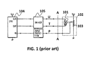
- a block diagram of such a circuit is replicated in FIG. 1 . It has a CPU 104 sending a PWM signal as a command-signal to a driver 105, which delivers power to a motor 101.
- a disadvantage of such motor control system is that the motor module 102 actually requires five wires, which implies additional handling and material cost. This may be important in applications where the distance between the CPU 104 and/or driver 105 on the one hand, and the motor 101 on the other hand is relatively large (e.g. larger than 50 cm), especially in high-volume, cost sensitive applications, such as e.g. air-conditioning systems for vehicles.
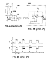
- EP0415655 describes a two-wire power and position control system between a central station 100 (i.e. the motor controller) and a remote station 102 (i.e. the motor module).
- FIGs. 2A, 2B and 2C of this document correspond to FIGs. 5 (left part), FIG. 7 and FIG. 8 of EP0415655(B1 ), respectively.
- a disadvantage of this circuit is that the motor can only be driven in a single direction, which makes this circuit unsuited for many practical applications.
- the present invention relates to a motor control system for controlling a plurality of DC-motors.
- the motor control system comprises:
- each DC motor can be driven in either direction (selectively clockwise and counter clockwise), and the motor position can be read even when the motor is substantially stationary.
- the motor may or may not be part of the motor module.
- the motor module may e.g. comprise or consist of a PCB with a potentiometer.
- the motor module may have a multi- pins connector for connection with the multi- wire interface.
- the motor module may have a plurality of two-pins connectors for connection with each of the motor terminals.
- the module may further have a rectifier circuit.
- the module may further have a voltage divider circuit.
- the number of DC motors is two, and the wire-interface has exactly five wires.
- This embodiment allows two motors to be driven over a five-wire interface instead of over a six-wire interface as known in the art, which leads to a 16% material savings, which is huge advantage, especially for mass-volume products such as automotive products, or consumer electronics products.
- the number of DC motors is three, and the wire-interface has exactly seven wires.
- This embodiment allows three motors to be driven over a seven-wire interface instead of over a nine-wire interface, which leads to a 22% material savings, which is a huge advantage, especially for mass-volume products such as automotive products, or consumer electronics products.
- the motor controller is adapted for reading the position feedback signal when the corresponding DC-motor is being powered.
- each variable impedance is a potentiometer.
- the potentiometer may e.g. be mechanically connectable or connected to the shaft of the motor, and electrically connectable or connected to the terminals of the DC-motor.
- the potentiometer may be adapted for receiving the same power signals as the corresponding DC-motor.
- the potentiometer may be arranged in parallel to the DC-motor, whereby the terminals of the potentiometer may be electrically connected to the terminals of the DC-motor, without any intermediate components, such as e.g. resistors, diodes, etc.
- the motor module may further comprise a rectifier for applying a DC voltage to its potentiometer when the corresponding DC-motor is being powered for turning in a first direction (e.g. clock-wise) or in a second direction (e.g. counter-clock-wise).
- a rectifier for applying a DC voltage to its potentiometer when the corresponding DC-motor is being powered for turning in a first direction (e.g. clock-wise) or in a second direction (e.g. counter-clock-wise).
- the motor controller may be adapted for providing a pulsed power signal as at least one of the first and second power signal.
- pulsed power signals are that they can easily be generated in an integrated circuit having general purpose input-output pins, or by using a pulse-width-modulator (PWM).
- PWM pulse-width-modulator
- the generation of such signals does not require a heavy CPU-load; and Digital-To-Analog convertors (DAC) and/or external filters (e.g. RC-filters) can also be avoided.
- DAC Digital-To-Analog convertors
- RC-filters external filters
- the motor torque can easily be determined by modifying the pulse duration (in case of discrete pulses), or the duty cycle (in case of a PWM-signal) of the power signals.
- the motor controller comprises:
- CMOS complementary metal-oxide-semiconductor
- the motor control system may further comprise at least one voltage divider, arranged for reducing the amplitude of the position feedback signals (Ps) to a range suitable for the at least one analog-to-digital-convertor.
- the voltage divider may be located on either side of the wire-interface, near the motor module or near the motor controller. Preferably there is a voltage divider for each of the position feedback signals.
- the or each voltage divider may consist of only two resistors. In other embodiments, the voltage divider may consist of only three resistors.
- An advantage of a voltage divider consisting of only two or three resistors is that it does not require active components, such as a buffer or amplifier.
- the motor controller may be provided with an algorithm for correcting a non-linear relation between the actual motor positions and the position feedback signals.
- the relation can be approximated by a linear curve, or a piece-wise linear curve having e.g. two or three linear portions.
- an accurate correction is needed, e.g. by using a look-up-table stored in memory, or by calculations using mathematical formulae.
- the present invention also relates to a motor module, as may be used in any of the motor control systems in accordance with the first aspect.
- the motor module is connectable to a plurality of DC-motors.
- the motor module comprises a plurality of variable impedances, each adapted for being operatively connected to one of the plurality of DC motors and for creating an impedance indicative of a position of said one DC-motor.
- the motor module is connectable via a wire interface to a motor controller, the number of wires of the wire interface being twice the number of DC-motors to be connected to the motor module, plus one.
- the motor module is adapted for receiving a plurality of first power signals, each for being applied to one of the DC-motors, and a single common second power signal for powering the plurality of DC-motors and for powering the plurality of variable impedances, and for generating a position feedback signal at a moment when the first and second power signals have different voltage levels.
- Such a motor module may be especially adapted for cooperating with a corresponding motor controller over the wire interface.
- the motor module may also comprise the DC-motor, in which case the potentiometer may be operatively connected to the DC-motor shaft, and may be electrically connected to the motor terminals.
- the motor module may for instance have a first connector with 2xN+1 pins for connection to the wire interface, N being the number of motors, and N second connectors having three pins for connecting one of the first power signals and the common second power signal to one of the motors, and for receiving the position signal from said motor.
- the motor module may comprise a single PCB (printed circuit board), or multiple PCB's, interconnected to each other, but need not necessarily comprise a PCB.
- the invention also relates to a motor controller for controlling a plurality of DC-motors, as may be used in such motor control system, the motor controller being connectable via a wire interface to one or more motor modules connectable to the plurality of DC-motors and comprising for each of the plurality of DC-motors a variable impedance adapted for being operatively connected to one of the DC motors and for creating an impedance indicative of a position of said one DC-motor.
- the motor controller is adapted for providing a plurality of first power signals, each for being applied to one of the DC motors, and for providing a single common power signal for powering the plurality of DC-motors.
- the motor controller is furthermore adapted for powering the plurality of variable impedances which are adapted for generating a position feedback signal when being powered.
- the motor controller is adapted for reading at least one of the position feedback signals at a moment when the corresponding first power signal and the common second power signal have different voltage levels.
- Such a motor controller may be especially adapted for cooperating with a corresponding motor module over the wire interface, for instance for cooperating with a motor module according to embodiments of the second aspect of the present invention.
- a motor controller in accordance with embodiments of the present invention is ideally suited for being implemented in an at least partly digital IC with a programmable CPU. By digitizing the position feedback-signal, any non-linearity of the system can be easily corrected in the digital domain. In addition, it allows the hardware to be simplified.
- the present invention also relates to a method for driving a plurality of DC-motors over a wire interface selectively in a first and second direction, whereby the number of wires of the wire-interface is twice the number of DC-motors plus one, and for reading the positions of the plurality of DC-motors.
- the method comprises the steps of: a) generating a plurality of first power signals and generating a single common second power signal, and applying the plurality of first power signals and the single common second power signal to the plurality of DC-motors over the wire interface, whereby at least one of the first power signals and the single common second power signal have different voltage levels for driving at least one of the DC-motors; b) generating at last one position feedback signal of said at least one driven DC-motor, and applying the at least one position feedback signal to the wire interface; c) determining at least one actual position of the at least one driven DC-motor based on the at least one position feedback signal; d) adjusting the plurality of first power signals and the single common second power signal based on the at least one actual motor position and on a plurality of predetermined motor positions, and applying the adjusted power signals to the wire interface.
- Such a method is especially adapted for powering a number of DC-motors and for reading their position over a wire interface having less than three wires per motor, as in accordance with embodiments of the present invention.
- each motor may be driven individually to different predetermined positions.
- the motors may be driven in a time division multiplexed manner, that is, in time slots. In embodiments of the present invention, only one motor is driven per time-slot, while the other motors are not powered in that particular time-slot. However, it also possible to drive more than one motor per time-slot.
- the motors may be driven in the same or opposite directions (e.g. clockwise / counter-clockwise), or may be kept in a stationary position, or any combination hereof.
- a "short positive pulse” or a “short negative pulse” simultaneously to all motors, for simultaneously reading out all of the motor positions, which is faster than reading each motor position one after the other. If the motors are in a stationary position, then preferably an opposite short pulse is applied to compensate for the first pulse.
- the determination of the actual position of the at least one driven DC-motor in step c) includes determining whether the corresponding momentary first power signal is larger or smaller than the common second power signal.
- a first calculation may be used, and when the motor is powered for turning in a second direction, e.g. "counter-clock-wise”, a second calculation different from the first calculation may be used.
- the calculations may be based e.g. on a first/second formula, or may be based e.g. on a first/second look-up table. This offers the advantage that a rectifier circuit can be avoided.
- Generating at least one position feedback signal may include generating a position feedback signal over a variable resistance, for instance a potentiometer.
- the method may further comprise rectifying the first and second power signal for powering the variable resistance, e.g. potentiometer. This offers the advantage that the calculation of the actual motor position from the position feedback signal can be simplified.
- generating the first and second power signals may comprise providing two different signals selected from the group of a supply voltage, a ground voltage and a pulse width modulated signal during a time interval, e.g. a predetermined time interval.
- a voltage difference equal to the supply voltage can be applied to the DC-motor to apply maximum positive or maximum negative torque, or no voltage difference to apply no torque, or a voltage with an intermediate average value to apply an intermediate average torque, during the time interval.
- generating a first and second power signal may comprise providing a pulse width modulated signal as one of the first and second power signals, and providing a DC signal as the other one of the first and second power signals.
- Each motor for which the first power signal and the second common power signal has a different voltage level, is actively driven.
- One or more motors may be simultaneously driven at any instant in time.
- the pulse width modulation signal and the DC signal have the same voltage level as the supply voltage.
- a voltage difference equal to the supply voltage can be applied to the DC-motor(s), allowing to provide maximum torque.
- This may be implemented by simply switching voltages or by using a PWM-module.
- Use of a PWM-module allows to create (on average) intermediate values of the torque, even for a constant time-slot.
- the values of the first and second power signals may be chosen so as to drive this one motor in the desired direction, e.g. clockwise, and the values of the first power signals of all the other motors may be chosen so as to provide no torque to these other motors, e.g. by applying to these motors a first power signal equal to the second power signal, or by providing as the first power signal a tri-state signal (also known as high-impedance state).
- the DC-signal may be substantially equal to half of the supply voltage.
- the DC-signal may be a fixed voltage between ground and the supply voltage, e.g. having a voltage level substantially equal to half of the supply voltage.
- a "pin" can be saved when using an IC, and software complexity can be reduced as this voltage can be made outside of the IC, while still allowing all of the DC-motors to be driven in either "clockwise” or “counter-clockwise” direction.
- the motors can be driven by only changing the duty-cycle of the first power signals.
- This embodiment has the additional advantage that all motors can be driven in each time-slot, in either direction, e.g. clockwise or counter-clockwise, substantially 100% of the time.
- a 50% duty cycle would typically correspond to actively maintaining the DC-motor position in a stable position, a duty cycle smaller resp. larger than 50% would cause the motor to turn in the first resp. second direction.
- the at least one of the first power signals may be set to tri-state.
- Using tri-state signals may simplify the software, provide less switching noise, cause less current spikes in the motor and over the wire-interface, and may thus create less EMI (electro-magnetic interference).
- the method may furthermore comprise digitizing the position feedback signal in an analog-to-digital-convertor.
- the method may furthermore comprise a step e) of reducing the amplitude of the position feedback signal.
- reducing the amplitude of the position feedback signal may include using a voltage divider comprising passive components, e.g. comprising only passive components. By avoiding active components such as buffers, power can be saved, and the circuit can be simplified. In addition, by choosing appropriate values for the components, the actual motor position can be determined with great precision, e.g. less than 1% position error.
- the method may further comprise a step f) of executing an algorithm for correcting a non-linear relation between the actual DC-motor position and the position feedback signal.
- algorithm may e.g. be implemented by using a look-up table and linear interpolation, or by using mathematical formulas. The skilled person can make a trade-off between position error, and the number of values and the number of bits per value in such a table.
- FIG. 1 shows a prior art circuit of a motor control system having a motor module 102 requiring five wires: two wires U, T for powering a motor 101, one wire P for providing a position feedback signal, and two additional wires for powering a potentiometer 103 with a power supply VCC and ground GND.
- the feedback signal Ps is not directly dependent on the voltage levels of the first and second power signals Us, Ts applied over the power wires U, T to the DC-motor 101, only indirectly when the motor 101 changes position.
- the feedback signal Ps indicative of the rotational position of the motor 101, is present even when no power is supplied to the motor 101 over the power wires U, T. Since the feedback signal Ps is always present (time continuous) and changes gradually as the motor 101 rotates clockwise or counter clockwise, such a feedback signal Ps is ideal for use in a time-continuous analog control circuit.
- the circuit of FIG. 1 is relevant for the present application mainly as an example of a motor-system with a DC-motor capable of rotating selectively both clockwise and counter clockwise, whereby the position of the motor 101 can be determined also in a stationary position of the motor (i.e. when not rotating), and requiring five wires for powering and position feedback.
- FIG. 2A shows another prior art power and position control system 100, also called “control station” connected to a remote motor module 102, also called “remote station”, shown in FIG. 2B over a two-wire interface U, T, for generating a physical displacement by a permanent magnet DC-motor 101.
- a pulsating voltage is applied to the link U, T as the power source for the DC motor 101.
- the physical displacement information of the motor 101 is extracted by the control station 100 within the off-cycles of the pulsating power signal Us on the wire U (i.e. when A is high, so that transistor 106 is off and no power pulse is sent to the motor 101).
- the remote station 102 is arranged to sequentially connect a variable impedance 103 to form part of a voltage divider, the change in impedance being used to affect a voltage derived from the voltage divider at the control station 100. Since one of the wires T is permanently connected to ground, and the other wire U can be driven only by a value equal to either of GND or the positive power supply +V, depending on the value of the input signal A, the motor 101 can only be driven in a single direction, e.g. "clockwise". Moreover, the diode D1 only allows current to flow in one direction through the motor 101. Thus this circuit is not suitable for driving the motor 101 in both directions (selectively clockwise and counter clockwise).
- the principle of providing position feedback is based on voltage division measured "between the power pulses".
- the pnp-transistor 106 when the input A is low, the pnp-transistor 106 is "on", and the voltage +V is applied to node B and thus to the line U for powering the motor 101, which will start rotating in a first direction, e.g. "clockwise” as long as the input A is low.
- the pnp-transistor 106 When the input A is set high, the pnp-transistor 106 is switched “off", and a voltage division will occur (over the resistors 107, and 108 in parallel with the resistors of the motor module 102). This will cause a voltage Vc, Vd or Ve to be placed on the two-wire interface U,T, which is indicative of the position of the motor 101.
- the position information is thus available during the "off"-periods, i.e. at a moment when no power is delivered to the motor 101 by the drive circuit 100.
- the line portions corresponding to the position feedback signals are indicated in FIG. 2C in thicker line width for illustrative purposes.
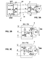
- FIG. 3A shows a motor power and position measurement system as can be used in embodiments of the present invention.
- the motor power and position measurement system comprises a motor control circuit 10 (left), also referred to as motor controller 10, and a motor module 2 (right).
- the motor module 2 is connected to the motor controller 10 via a three-wire interface 13, comprising three wires U, T, P for transporting resp. a first and second power signal Us, Ts from the motor controller 10 to the motor module 2, and a position feedback signal Ps from the motor module 2 to the motor controller 10.
- the motor module 2 shown in FIG. 3A comprises a DC-motor 1, and a potentiometer 3 operatively, e.g. mechanically, coupled to the motor 1 for converting a position, e.g.
- the motor module 2 further comprises a rectifier circuit 12, comprising four diodes D2-D5.
- the motor controller 10 may optionally further comprise a voltage divider 11, for reducing the voltage level of the position feedback signal Ps, e.g. to the input range of an analog-to-digital (ADC)-convertor which may be present in the motor controller 10.
- ADC analog-to-digital
- the motor 1 can be selectively driven in either direction, i.e. clockwise or counter clockwise, by applying suitable first and second power signals Us, Ts to the power lines U, T of the three-wire interface 13.
- the position of the motor 1 can be determined by means of the signal Ps placed on the third wire P by the potentiometer 3.
- the motor 1 may also be external to the motor module 2, in which case the potentiometer 3 is operatively connectable, and electrically connectable to the motor 1.
- the voltage divider 11, which is optional, comprises, e.g. consists of two resistors R3, R4 connected in series, the series connection at one end being connected to ground GND, and at the other end being connected to a third node (also called output node) of the potentiometer 3.
- a third node also called output node
- other voltage reducing circuits are also possible, e.g. a circuit comprising a buffer.
- the simplest (and cheapest) hardware solution is a voltage divider consisting of only two resistors, without a buffer.
- FIG. 3B illustrates what happens when a first power signal Us having a momentary voltage level larger than that of the second power signal Ts is applied to the first resp. second power line U, T of the motor module 2.
- Us is set to a high voltage, e.g. 12V DC
- Ts is set to a low voltage, e.g. 0V DC
- a current Im will flow through the motor 1 as indicated by the arrow, for powering the motor 1 for turning in a first direction, e.g. clockwise.
- a first direction e.g. clockwise.
- Ps is an indication of the position of the motor 1 when powered for turning clockwise.
- FIG. 3C is a variant of FIG. 3B , and illustrates what happens when a voltage Us having a momentary value smaller than Ts is applied to the first resp. second power line U, T of the motor module 2.
- Us is set to a low voltage, e.g. 0 V DC
- Ts is set to a high voltage, e.g. 12 V DC
- a current Im will flow through the motor 1 as indicated by the arrow, for powering the motor 1 for turning in a second direction opposite the first direction, e.g. counter clockwise.
- a voltage Us having a momentary value smaller than Ts is applied to the first resp. second power line U, T of the motor module 2.
- Ps is an indication of the position of the motor 1 when the motor 1 is powered for turning counter clockwise.
- the position feedback signal Ps When the motor 1 is powered, the position feedback signal Ps will assume values in a predetermined range, e.g. in the range of about 0.6 V to about 11.4 V (assuming a 12 V supply voltage, and assuming a 0,6 V voltage drop over the diodes).
- the motor controller 10 is at least partly digital, and comprises an analog-to-digital convertor ADC1 in the motor controller 10, the voltage range of the feedback signal Ps needs to be reduced to the input range of the ADC, which is e.g. only 0.0 V to 1.0 V.
- a function of the optional voltage divider 11, if present in the motor control system 10 of FIG. 3A is therefore to decrease the amplitude of the position feedback signal Ps to a smaller value.
- the optional voltage divider 11 if present in the motor control system 10 of FIG. 3A , is therefore to decrease the amplitude of the position feedback signal Ps to a smaller value.
- the motor module 2 only requires three instead of five wires, thus saving material and handing costs, and that it enables the motor 1 to be driven selectively in either direction (clockwise or counter clockwise), which makes it suitable for many applications, and that the motor position can be read, even when the motor 1 is in a stationary position. This last aspect is further explained below.
- a "short" pulse (e.g. less than 5 ms, or less than 1 ms, e.g. less than 500 ⁇ s) can be applied to the power wires U, T.
- the first pulse may be a "counter clockwise pulse”
- a second, "clockwise pulse” may be given to compensate for this first pulse.
- the motor controller 10 may repeatedly, e.g. periodically apply clockwise or counter clockwise power pulses, having a fixed or a variable pulse duration, to the power wires U, T for moving the motor 1 to the desired position.
- clockwise and counter clockwise power pulses may alternately be applied for moving the motor 1 marginally clockwise, and marginally back counter clockwise, thereby in effect maintaining the motor position with a given torque.
- the motor position can be measured, and the duration of the "clockwise” and "counter clockwise power pulses” may be adjusted for maintaining the motor position.
- Such a combination is not regarded as a "power pulse”, since the motor 1 will not "see” a voltage difference over its terminals.
- the examples are given for 0 V and 12 V, the present invention is not limited to these values, and other voltage values smaller than 12 V, or larger than 12 V may also be used.
- the motor controller 10 is an integrated circuit having a programmable digital processing unit CPU and general purpose input-output pins io1-io5, such power pulses may e.g. be easily created by setting some of the io-pins to logical '1' or '0'.
- external circuitry such as e.g. a pnp-transistor may optionally be added.
- PWM1 pulse-width modulation module
- a PWM-signal can be used as one or both of the power signals Us, Ts.
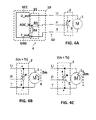
- FIG. 4A shows a motor power and position measurement system as can be used in embodiments of the present invention.
- the motor module 2 has a potentiometer 3 operatively, e.g. mechanically, coupled to the motor 1 for converting a position, e.g. rotational position of the motor 1 into a variable resistance. It is to be noted, however, that this motor module 2 does not have a rectifier circuit 12, thus compared to FIG. 3A the four diodes D2-D5 can be omitted.
- the potentiometer 3 is connected in parallel with the motor 1. This circuit also requires only three wires U, T, P for powering the motor 1 and for measuring the motor position.
- the motor 1 may be part of the motor module 2 or not, and the motor controller 10 may optionally further comprise a voltage divider 11 for reducing the voltage range of the position feedback signal Ps to a range acceptable for an analog-to-digital (ADC)-convertor which may be present in the motor controller 10, as described above.
- the motor 1 can be selectively driven in either direction, i.e. clockwise or counter clockwise, by applying suitable first and second power signals Us, Ts to the power lines U, T of the three-wire interface 13.
- suitable first and second power signals Us, Ts to the power lines U, T of the three-wire interface 13.
- Most of what was described for the embodiment of FIGs. 3A to 3C is also applicable for the circuit of FIG. 4A , e.g. that the motor position can be read by applying a short "clockwise” or “counter clockwise power pulse", but there is an important difference in the interpretation of the position feedback signal Ps, due to the fact that this motor module 2 does not have rectifier, as will be described next.
- FIG. 4B shows what happens when a voltage Us having a momentary voltage level larger than that of Ts is applied to the first resp. second power line U, T of the motor module 2.
- a current Im will flow through the motor 1 as indicated by the arrow, for powering the motor 1 for turning in a first direction, e.g. "clockwise”.
- a current will also flow through the potentiometer 3 thereby creating a position signal Ps which is applied to the third wire P of the three-wire interface 13.
- the value of Ps is an indication of the position of the motor 1.
- FIG. 4C is a variant of FIG. 4B , and shows what happens when a voltage Us having a momentary voltage level smaller than that of Ts is applied to the first resp. second power line U, T of the three-wire interface 13.
- a current Im will flow through the motor 1 as indicated by the arrow, for powering the motor 1 for turning in a second direction opposite the first direction, e.g. "counter clockwise”.
- a current will also flow through the potentiometer 3 thereby creating a position signal Ps which is applied to the third wire P of the three-wire interface 13.
- the value of Ps is an indication of the position of the motor 1.
- An important difference between the situation in FIG. 4B and FIG. 4C is that the direction of the current through the potentiometer 3 depends on whether the motor module 2 is powered for turning "clockwise” and for turning "counter clockwise”. This requires special treatment as will be described next.
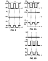
- FIG. 5 shows an example of first and second power signals Us, Ts applied to the first and second power wire U, T of the three-wire interface 13, as may be used in FIG. 4B .
- FIG. 5 also shows a corresponding position-feedback signal Ps, in the example having an amplitude of 3V (assuming that the actual motor position was 25% between its outermost counter clockwise position and its outermost clockwise position).
- this signal Ps should be scaled down. It is to be noted that the position information Ps is available and valid only when the first and second power signals Us, Ts differ, i.e. when power is delivered to the motor 1, e.g.
- the powering signals Us, Ts of FIG. 5 would normally cause the motor 1 to turn clockwise. (It is to be noted that the signal Ts is deliberately shown slightly above the time-axis, for illustrative purposes).
- the position signal Ps is caused by a voltage division applied by the potentiometer 3 while the motor 1 is being powered.
- the first power signal Us is generated as a PWM-signal, in the example having a duty of about 40%, but this value may be dynamically changed by the motor controller 10, e.g. depending on the difference between the actual motor position and the desired (target) motor position, or depending on an external force exerted upon the motor 1, which force should be counteracted for keeping the motor in a stable target position.
- FIG. 6A shows an example of first and second power signals Us, Ts applied to the first and second power wire U, T of the three-wire interface 13 as may be used in FIG. 4C .
- FIG. 6A also shows the corresponding position-feedback signal Ps, assuming that the actual motor position is still 25%. It should not come as a surprise that when the motor is powered in the opposite direction (e.g. for turning "counter clockwise” in case of FIG. 6A ), that the position signal Ps abruptly changes from 3 V to 9 V in this example. This is because the polarity of the nodes of the potentiometer 3 in FIG. 4C are not the same as in FIG. 4B , in contrast to the circuit of FIG. 3A having a rectifier 12.
- the signal Ps in FIG. 6A should be scaled down. It is to be noted that the position information Ps is again available only when the first and second power signals Us, Ts differ, i.e. at time instances when power is delivered to the motor 1, as indicated by the dotted vertical lines. The powering signals of FIG. 6A would normally cause the motor 1 to turn counter clockwise.
- FIG. 6B shows another set of power signals Us, Ts which would obtain the same effect on the motor 1 as the signals of FIG. 6A , i.e. powering the motor 1 for turning "counter clockwise", and would result in the same position information, taking into account the time-instances when the position signal is valid, and assuming the motor position is still 25%.
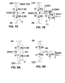
- FIG. 7A and FIG. 8A explain why the voltage value of the position feedback signal Ps "suddenly jumps" from 3 V to 9 V when the motor module 1 previously being powered for rotation in the first direction (e.g. clockwise, corresponding to FIG. 4B and FIG. 5 ), is subsequently powered for rotation in the second direction (e.g. counter clockwise, corresponding to FIG. 4C and FIG. 6A ).
- FIG. 7B and FIG. 8B show equivalent circuits for the measurement circuitry, as part of the control circuit in FIG. 4A , for the case where the optional voltage divider circuit 11 is present, and consists of two resistors R3, R4.
- R3 13 k ⁇
- R4 1 k ⁇ , resulting in a maximum ADC input value of about 0,85 V.
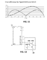
- the ADC input voltage (i.e. the voltage over R4) can be calculated for each motor position, as shown in FIG. 9 .
- the two curves show the motor position (in % of the rotation angle) versus the feedback signal Ps after voltage division for the measurement circuits of FIG. 7B and FIG. 8B . It is to be noted that these curves are not linear anymore, because current is drawn by the voltage divider 11. Depending on whether the first power signal Us is larger or smaller than the second power signal Ts, either one of the two curves should be used for converting the measured position signal Ps into the actual motor position.
- the values of these curves may be stored in a look-up table in a memory of the motor controller 10, or may be calculated when needed using mathematical formulae, e.g. implemented in software in the CPU of the motor controller 10.
- FIG. 10A and FIG. 10B show variants of the voltage divider circuit 11, each having three resistors R3, R4, R5, as can be used in the circuit of FIG. 3A and FIG. 4A .
- An advantage of adding the extra resistor R5 as in the circuits of FIG. 10A and FIG. 10B is that it may provide a more balanced voltage division for providing a smaller non-linearity error as compared to a voltage divider consisting of only two resistors R3, R4.
- the values for R3, R4, R5 may e.g.
- the maximum deviation between the real motor position, and the calculated motor position as obtainable from the curves of FIG. 9 is less than 0.35%, which is sufficiently accurate for most applications, e.g. for positioning air-conditioning valves in cars.
- the motor module 2 of FIG. 4A does not require a rectifier circuit 12, at the expense of a slightly increased complexity (two curves instead of only one) for converting the position feedback signal Ps into the actual motor position.
- this complexity can be easily implemented in software if the motor controller 10 has a programmable digital processing unit CPU, the increased complexity should not be over-estimated, because such processor already implements a servo-algorithm, which is more complex than a function or a look-up table.
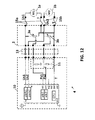
- FIG. 12 shows an example of motor control system 4 according to embodiments of the present invention, whereby a motor controller 10 comprises an integrated motor control IC for driving two DC-motors M1, M2, and wherein the motor module 2 may or may not comprise the two motors M1, M2.
- two short (e.g. less than 5 cm) wires 15a, 15b may be used to interconnect the motor module 2 and the motors 1 a, 1 b.
- the motor module 2 is connectable via a five-wire interface 13 to the motor controller 10.
- the length of the wire-interface 13 may be larger than 50 cm, or larger than 1 m, or even larger than 2 meters.
- the first motor M1 receives a first power signal Us1 and a second power signal T
- the corresponding potentiometer 3a receives the same first and second power signals Us1 and Ts, and is adapted to provide an output voltage as the first position signal Ps1 of the first motor M1 to the motor controller 10.
- the second motor M2 receives another first power signal Us2, but the same second power signal Ts, and the corresponding potentiometer 3b provides a second position signal Ps2 to the motor controller 10.
- the second power signal Ts is common for the two motors, or in a more generalised case of more than two motors, common to at least two motors, e.g. to all the motors.
- the motor controller 10 has two output pins U, V for providing the first power signals U1s, U2s to the respective motors M1, M2. These pins may be set low (GND), high (VDD), tri-state (Z), or may be connected to the outputs of two internal PWM-modules PWM1, PWM2.
- a single general purpose input-output pin e.g. io4 is used for providing the common second power signal Ts.
- the second power signal Ts can be generated by a PWM-module.
- the second power signal Ts can be generated by two general purpose input-output pins (GPIO), as illustrated in FIG. 13 .
- the pins io4 and io5 are used for controlling an external H-bridge 14 for generating the second power signal Ts as one of the following signals: ground GND, or the supply voltage VDD, or a tri-state signal Z, whereby Ts is to be commonly applied to each of the two motors.
- H-bridges are well known in the art of motor control, and need not be explained further herein.
- two pins io0, io1 may be used for receiving the position feedback signals Ps1, Ps2 from the potentiometers 3a and 3b respectively. These pins io0, io1 may be coupled to two internal analog-to-digital convertors ADC1, ADC2 for converting the position feedback signals Ps1, Ps2 to digitized values. In another embodiment (not shown), a single ADC could be sufficient, provided that each of the two io-pins io0, io1 can be routed thereto.
- the motor controller 10 further has a digital processor, e.g.
- the CPU may also implement a servo control loop by determining suitable first power signals Us1, Us2 and second power signal Ts for driving each of the two motors M1, M2 towards their target positions, e.g. to a first and a second predetermined target position.
- the integrated motor control IC of FIG. 12 is adapted for driving the motors in alternating time slots, one for each motor, thereby implementing two simultaneous servo control loops.
- each motor M1, M2 is brought to its target position before the other motor is activated.
- the position of the first motor M1 is measured as described above, e.g. by applying a short "clockwise or counter clockwise power pulse".
- a suitable DC-signal and/or pulse signal and/or PWM-signal is determined and applied to the first motor 1, by providing appropriate first and second power signals Us1, Us2 and T to the five-wire interface 13.
- the first power signal Us1 to the first motor may be set to +12V, and the second power signal T to the first motor may be 0 V, but this is also the second power signal of the second motor M2. If no torque is to be exerted on the second motor M2, the first power signal Us2 to the second motor M2 may be set equal to the second power signal Ts, in this example 0 V, or may be set to tri-state.
- a method similar to that described in US 5,705,907 may be used to limit the overshoot.
- the time required for bringing the first motor M1 in its desired position depends on several factors, for example: the angular distance between the start-position and the end-position, any external force exerted upon the first motor M1, etc.
- the first power signal Us1 may be set to tri-state, or may be set equal to the value of Ts.
- the second motor M2 is brought to its target position.
- the second power signal T may then be set to +12V, and the first power signal Us2 for the second motor M2 may be set to 0V, during a second time interval, and the first power signal Us1 to the first motor may then also be set to +12V or to tri-state. And then the cycle repeats.
- each motor in its desired position, one after the other, it is also possible to drive the motors M1, M2 in a time-multiplexed manner, for example to drive a first motor during a first time slot of for example 5 ms, then the second motor during 5 ms, etc, but any other method known to the person skilled in the art of driving motors, may also be used.
- the motor controller 10 and the voltage dividers 11 may be located on a first PCB.
- This first PCB would be connected to the potentiometers 3a and 3b via a five-wire interface 13.
- the potentiometers 3a, 3b could be located on a second PCB (as illustrated), which second PCB could be connected to each motor via two pairs of two wires each.
- the second PCB having a five-pins connector and a pair of two-pin connectors and two potentiometers could be seen as the motor module 2.
- each potentiometer 3a, 3b could be located on a separate, small, PCB nearby the corresponding motor, and each of these small PCBs could be connected to the five-wire interface 13, e.g. via an interface-board (not shown) having a five-pins connector with wires U1, U2, P1, P2, T, and two three-pin connectors with wires U1, P1, T, and U2, P2, T respectively, which would be interconnected on the interface-board.
- the motor module 2 could be considered as to comprise the interface-board and the two small PCBs with the potentiometers. But other hardware configurations are also possible, as will be appreciated by the person skilled in the art.
- the second power signal Ts is permanently set to VDD/2, e.g. to +6 V.
- the first power signals Us1, Us2 as any of a low voltage, e.g. 0 V DC-signal, or a high voltage, e.g. 12 V DC signal, or a PWM-signal with an amplitude of the high voltage signal, e.g. 12 V, and a fixed or variable duty-cycle
- the second power signal T need not be generated by the motor controller 10, thus at least one io-pin, io4 in FIG. 12 , io4 and io5 in FIG. 13 , can be saved.
- a position signal Ps1, Ps2 is present for all the motors M1, M2 at the same time, and a torque is exerted upon all the motor all the time, if desired.
- the motor controller 10 of FIG. 12 is thus able to drive two motors M1, M2 in any direction, simultaneously or one after the other or a mix thereof, and to measure their positions, even if they are stationary, over a five-wire interface 13.
- the present invention is, however, not limited to two motors, but also works for more than two motors, for example for driving three motors over a seven-wire interface 13.
- the skilled person can readily extend the circuit of FIG. 12 to drive three motors, e.g. by replacing the five-wire interface 13 by a seven-wire interface 13, by using pin W to provide a signal Us3 as the first power signal for the third motor M3 (not shown), and by using pin io2 to receive a third position signal Ps3 (not shown), and by adding a third voltage divider (not shown), and by adding a third potentiometer (not shown) on the motor module 2.
- the algorithm to drive the three motors can work in similar manner as described above for two motors, e.g. by using series of three time-slots, wherein the first time-slot is used to drive the first motor M1 while leaving the second and third motor un-powered, etc.
- the present invention is not limited to two or three motors, but can also be used to drive more than three motors, e.g. ten motors, or even more.
Landscapes
- Engineering & Computer Science (AREA)
- Power Engineering (AREA)
- Control Of Multiple Motors (AREA)
- Arrangements For Transmission Of Measured Signals (AREA)
Applications Claiming Priority (1)
| Application Number | Priority Date | Filing Date | Title |
|---|---|---|---|
| GBGB1211541.6A GB201211541D0 (en) | 2012-06-29 | 2012-06-29 | Method and system for powering and measuring position of a DC-motor over a three-wire interface |
Publications (2)
| Publication Number | Publication Date |
|---|---|
| EP2680431A2 true EP2680431A2 (de) | 2014-01-01 |
| EP2680431A3 EP2680431A3 (de) | 2017-02-15 |
Family
ID=46721603
Family Applications (1)
| Application Number | Title | Priority Date | Filing Date |
|---|---|---|---|
| EP13174587.9A Withdrawn EP2680431A3 (de) | 2012-06-29 | 2013-07-01 | Verfahren und System zur Versorgung und Positionsmessung einer Vielzahl von Gleichstrommotoren über eine Drahtschnittstelle |
Country Status (3)
| Country | Link |
|---|---|
| US (1) | US8963473B2 (de) |
| EP (1) | EP2680431A3 (de) |
| GB (1) | GB201211541D0 (de) |
Cited By (1)
| Publication number | Priority date | Publication date | Assignee | Title |
|---|---|---|---|---|
| US10630148B2 (en) | 2014-07-02 | 2020-04-21 | Continental Automotive Gmbh | Actuator having a position sensor |
Families Citing this family (4)
| Publication number | Priority date | Publication date | Assignee | Title |
|---|---|---|---|---|
| CN104682792B (zh) * | 2013-11-27 | 2020-01-31 | 德昌电机(深圳)有限公司 | 直流电机控制电路 |
| US11736047B2 (en) * | 2019-09-25 | 2023-08-22 | Allegro Microsystems, Llc | BLDC motor controller/driver |
| CN112928950B (zh) * | 2021-01-25 | 2022-12-13 | 上海雷诺尔科技股份有限公司 | 基于光纤复用的数据传输系统和高压软起动控制系统 |
| DE102023204888A1 (de) * | 2022-05-31 | 2023-11-30 | Robert Bosch Gesellschaft mit beschränkter Haftung | Steer-by-Wire-System zur Bedienung von Lenkrad und Lenksäule |
Family Cites Families (11)
| Publication number | Priority date | Publication date | Assignee | Title |
|---|---|---|---|---|
| DE3141068A1 (de) | 1981-10-16 | 1983-05-05 | Richard Hirschmann Radiotechnisches Werk, 7300 Esslingen | Nachlaufsteuerung fuer einen antennenrotor |
| JPS6096381A (ja) * | 1983-09-09 | 1985-05-29 | Hitachi Ltd | レ−ザビ−ム制御装置 |
| US5253138A (en) * | 1989-07-04 | 1993-10-12 | Ets Cousin Freres | Simplified supplying system of the position identification potentiometers of electronic memory mechanisms of a motor for setting automobile vehicle seats and the like |
| CA2018733C (en) * | 1989-09-01 | 2000-04-25 | Kwok-Chuen Ho | Two-wire power and position control system |
| US5545961A (en) | 1992-10-21 | 1996-08-13 | Robert Bosch Gmbh | Electric motor drive |
| DK95094A (da) | 1994-08-17 | 1996-02-18 | Linak As | Aktuator med positionsdetektor |
| JP3255813B2 (ja) * | 1994-12-27 | 2002-02-12 | アルプス電気株式会社 | サーボモータの駆動制御装置 |
| US5742143A (en) * | 1995-01-20 | 1998-04-21 | Kabushiki Kaisha Sankyo Seiki Seisakusho | Motor control system with selectively operated A/D convertor |
| US20050046367A1 (en) | 2003-08-29 | 2005-03-03 | Johnson Controls Technology Company | Circuit for providing power to multiple electrical devices |
| US20070103103A1 (en) | 2005-11-09 | 2007-05-10 | Maue H W | Bi-directional motor voltage conversion circuit |
| GB0608973D0 (en) | 2006-05-06 | 2006-06-14 | Gunton Bruce S | Aperture closure member control arrangements |
-
2012
- 2012-06-29 GB GBGB1211541.6A patent/GB201211541D0/en not_active Ceased
-
2013
- 2013-07-01 US US13/932,488 patent/US8963473B2/en not_active Expired - Fee Related
- 2013-07-01 EP EP13174587.9A patent/EP2680431A3/de not_active Withdrawn
Non-Patent Citations (1)
| Title |
|---|
| None * |
Cited By (2)
| Publication number | Priority date | Publication date | Assignee | Title |
|---|---|---|---|---|
| US10630148B2 (en) | 2014-07-02 | 2020-04-21 | Continental Automotive Gmbh | Actuator having a position sensor |
| EP3078112B1 (de) * | 2014-07-02 | 2020-10-14 | Vitesco Technologies GmbH | Aktuator mit positionssensor |
Also Published As
| Publication number | Publication date |
|---|---|
| EP2680431A3 (de) | 2017-02-15 |
| US20140002000A1 (en) | 2014-01-02 |
| US8963473B2 (en) | 2015-02-24 |
| GB201211541D0 (en) | 2012-08-15 |
Similar Documents
| Publication | Publication Date | Title |
|---|---|---|
| US8963473B2 (en) | Method and system for powering and measuring positions of a plurality of DC-motors over a wire interface | |
| JP6422278B2 (ja) | 電力制御回路 | |
| JP5668949B2 (ja) | 逆起電力検出回路とそれを用いたモータ駆動制御装置並びにモータ | |
| CN113454904B (zh) | 带有功率反馈回路的电机控制器 | |
| CN102136819A (zh) | 马达驱动电路 | |
| CN109905060B (zh) | 半导体设备、电机驱动系统和电机控制程序 | |
| WO2008007510A2 (en) | Electric motor, drive system employing multiple electric motors, and method for controlling the same | |
| WO2007001800A2 (en) | Digital motor control system and method | |
| US7015663B1 (en) | Brushless motor drive device | |
| US6924611B1 (en) | Brushless motor drive device | |
| US9178451B2 (en) | Controller for brushless DC motor with flexible startup and method therefor | |
| US20010011847A1 (en) | Electronically-commutated motor | |
| US20150188463A1 (en) | Controller for brushless dc motor with low torque ripple and method therefor | |
| JP2013255309A (ja) | モータ駆動回路およびそれを用いた電子機器 | |
| US9602030B2 (en) | Motor drive circuit and motor thereof | |
| US5767653A (en) | Variable speed AC induction motor controller | |
| JP5060750B2 (ja) | モータ駆動回路およびそれを用いた電子機器 | |
| JP5582439B2 (ja) | モータ駆動装置 | |
| NL8000080A (nl) | Stuursignaalgever. | |
| US7102320B1 (en) | Half-bridge control circuit | |
| US5086492A (en) | Switching current regulator for motor control | |
| US11757384B2 (en) | Plural-fans driving apparatus | |
| JP2788024B2 (ja) | 無集電子直流電動機 | |
| JP2008118842A (ja) | モータ制御装置 | |
| JP6818662B2 (ja) | モータ駆動制御装置とモータ駆動制御方法 |
Legal Events
| Date | Code | Title | Description |
|---|---|---|---|
| PUAI | Public reference made under article 153(3) epc to a published international application that has entered the european phase |
Free format text: ORIGINAL CODE: 0009012 |
|
| AK | Designated contracting states |
Kind code of ref document: A2 Designated state(s): AL AT BE BG CH CY CZ DE DK EE ES FI FR GB GR HR HU IE IS IT LI LT LU LV MC MK MT NL NO PL PT RO RS SE SI SK SM TR |
|
| AX | Request for extension of the european patent |
Extension state: BA ME |
|
| PUAL | Search report despatched |
Free format text: ORIGINAL CODE: 0009013 |
|
| AK | Designated contracting states |
Kind code of ref document: A3 Designated state(s): AL AT BE BG CH CY CZ DE DK EE ES FI FR GB GR HR HU IE IS IT LI LT LU LV MC MK MT NL NO PL PT RO RS SE SI SK SM TR |
|
| AX | Request for extension of the european patent |
Extension state: BA ME |
|
| RIC1 | Information provided on ipc code assigned before grant |
Ipc: H02P 5/68 20060101ALI20170110BHEP Ipc: H02P 7/29 20160101AFI20170110BHEP |
|
| 17P | Request for examination filed |
Effective date: 20170814 |
|
| RBV | Designated contracting states (corrected) |
Designated state(s): AL AT BE BG CH CY CZ DE DK EE ES FI FR GB GR HR HU IE IS IT LI LT LU LV MC MK MT NL NO PL PT RO RS SE SI SK SM TR |
|
| 17Q | First examination report despatched |
Effective date: 20180914 |
|
| GRAJ | Information related to disapproval of communication of intention to grant by the applicant or resumption of examination proceedings by the epo deleted |
Free format text: ORIGINAL CODE: EPIDOSDIGR1 |
|
| GRAP | Despatch of communication of intention to grant a patent |
Free format text: ORIGINAL CODE: EPIDOSNIGR1 |
|
| GRAP | Despatch of communication of intention to grant a patent |
Free format text: ORIGINAL CODE: EPIDOSNIGR1 |
|
| GRAJ | Information related to disapproval of communication of intention to grant by the applicant or resumption of examination proceedings by the epo deleted |
Free format text: ORIGINAL CODE: EPIDOSDIGR1 |
|
| GRAJ | Information related to disapproval of communication of intention to grant by the applicant or resumption of examination proceedings by the epo deleted |
Free format text: ORIGINAL CODE: EPIDOSDIGR1 |
|
| GRAP | Despatch of communication of intention to grant a patent |
Free format text: ORIGINAL CODE: EPIDOSNIGR1 |
|
| GRAP | Despatch of communication of intention to grant a patent |
Free format text: ORIGINAL CODE: EPIDOSNIGR1 |
|
| INTG | Intention to grant announced |
Effective date: 20190807 |
|
| INTG | Intention to grant announced |
Effective date: 20190807 |
|
| INTC | Intention to grant announced (deleted) | ||
| INTG | Intention to grant announced |
Effective date: 20190830 |
|
| STAA | Information on the status of an ep patent application or granted ep patent |
Free format text: STATUS: THE APPLICATION IS DEEMED TO BE WITHDRAWN |
|
| 18D | Application deemed to be withdrawn |
Effective date: 20200110 |