EP2680200B1 - Outil de fabrication comportant un dispositif RFID monté à l'intérieur d'une inclusion diélectrique - Google Patents
Outil de fabrication comportant un dispositif RFID monté à l'intérieur d'une inclusion diélectrique Download PDFInfo
- Publication number
- EP2680200B1 EP2680200B1 EP13171917.1A EP13171917A EP2680200B1 EP 2680200 B1 EP2680200 B1 EP 2680200B1 EP 13171917 A EP13171917 A EP 13171917A EP 2680200 B1 EP2680200 B1 EP 2680200B1
- Authority
- EP
- European Patent Office
- Prior art keywords
- tool
- rfid device
- dielectric inclusion
- dielectric
- inclusion
- Prior art date
- Legal status (The legal status is an assumption and is not a legal conclusion. Google has not performed a legal analysis and makes no representation as to the accuracy of the status listed.)
- Active
Links
Images
Classifications
-
- G—PHYSICS
- G06—COMPUTING; CALCULATING OR COUNTING
- G06K—GRAPHICAL DATA READING; PRESENTATION OF DATA; RECORD CARRIERS; HANDLING RECORD CARRIERS
- G06K19/00—Record carriers for use with machines and with at least a part designed to carry digital markings
- G06K19/06—Record carriers for use with machines and with at least a part designed to carry digital markings characterised by the kind of the digital marking, e.g. shape, nature, code
- G06K19/067—Record carriers with conductive marks, printed circuits or semiconductor circuit elements, e.g. credit or identity cards also with resonating or responding marks without active components
- G06K19/07—Record carriers with conductive marks, printed circuits or semiconductor circuit elements, e.g. credit or identity cards also with resonating or responding marks without active components with integrated circuit chips
- G06K19/077—Constructional details, e.g. mounting of circuits in the carrier
- G06K19/07749—Constructional details, e.g. mounting of circuits in the carrier the record carrier being capable of non-contact communication, e.g. constructional details of the antenna of a non-contact smart card
-
- G—PHYSICS
- G06—COMPUTING; CALCULATING OR COUNTING
- G06K—GRAPHICAL DATA READING; PRESENTATION OF DATA; RECORD CARRIERS; HANDLING RECORD CARRIERS
- G06K19/00—Record carriers for use with machines and with at least a part designed to carry digital markings
- G06K19/06—Record carriers for use with machines and with at least a part designed to carry digital markings characterised by the kind of the digital marking, e.g. shape, nature, code
- G06K19/067—Record carriers with conductive marks, printed circuits or semiconductor circuit elements, e.g. credit or identity cards also with resonating or responding marks without active components
- G06K19/07—Record carriers with conductive marks, printed circuits or semiconductor circuit elements, e.g. credit or identity cards also with resonating or responding marks without active components with integrated circuit chips
- G06K19/077—Constructional details, e.g. mounting of circuits in the carrier
Definitions
- a factory for producing large commercial aircraft may include thousands of high-precision tools dispersed over a very large area.
- Floor areas of the largest factories are on the order of millions of square feet.
- RFID tags may be embedded in the tools, but the embedded tags have limited ranges.
- US 2006/0043178 relates to implementations of an instrument having an RFID tag formed in or on the material of its handle.
- One or more antenna segments of the RFID tag may be formed from conductive material printed or applied to a surface of the material.
- the antenna segments may be formed from a conductive foil applied to the surface of the elastic material of the handle.
- At least a portion of the RFID tag may be covered by a protective material.
- US 2003/0156033 relates to means for the assembly, retention and physical protection of a radio frequency identification tag installed in recess holes machined in drill pipe and tools utilized in drilling oil and gas wells. Claim 1 is delimited against this document.
- the invention is defined by claim 1.
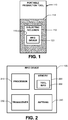
- FIG 1 illustrates a portable production tool 110 having a dielectric inclusion 112 and a radio frequency identification (RFID) device 120 mounted in the dielectric inclusion 112.
- RFID radio frequency identification
- the production tool 110 is not limited to anything in particular. Examples of the tool 110 may include, without limitation, manual tools such as screw drivers, wrenches, and portable power feed tools, and other larger shop tools such as grinders, saws, and lathes.
- That portion 114 of the tool 110 having the dielectric inclusion 112 is made of a nonconducting material.
- the portion 114 may be part of, for example, a handle, tool holder, tool case, or tool cover of the tool 110.
- the dielectric inclusion 112 includes a cavity that is defined by inner walls 116 of the tool portion 114.
- the RFID device 120 may be mounted to one of the walls 116. There is space between the other walls 116 and the RFID device 120. The space is filled with a dielectric inclusion medium.
- the shape of the dielectric inclusion 112 is not limited to anything in particular, except to follow the contour of the tool 110. Examples of the shape of the dielectric inclusion 112 may include, without limitation, cuboid (box shape), right circular cylinder, annular shaped cavity, and C-shaped.
- the electrical property (permittivity) of the material used to make the tool portion 114 is different than that of the inclusion medium.
- the permittivity of the tool portion 114 may be higher or lower than that of the dielectric inclusion medium 112.
- the permittivity of the dielectric inclusion medium is unity, which constitutes an air box.
- the dielectric inclusion 112 creates a discontinuity in the tool portion 114. Due to this discontinuity, electromagnetic waves (from an RFID reader during interrogation, or the RFID device 120 during transmission) incident on the tool 110 undergo reflections. Depending on the size, shape, location, and permittivity of the dielectric inclusion 112 and size, shape, and permittivity of the tool portion 114, incident and the reflected waves undergo constructive interference. The constructive interference enhances electromagnetic field strength at specific locations within the tool.
- the RFID device 120 of Figure 2 includes a processor 210, machine-readable memory 220, transceiver 230, and antenna 240.
- the antenna 240 may be linearly polarized.
- the RFID device 120 may be supplied with operating power by a battery or other internal source. In other embodiments, the power may be harvested or it may be supplied by the tool 110 or other external source.
- Tool information 222 is stored in the memory 220.
- the tool information 222 may identify the tool 110, for instance, by a number (e.g., a part number, serial number, etc.).
- the information 222 may identify a production job to be performed by the tool 110.
- a production job may be identified, for instance, by assembly procedure number.
- the information 222 may identify tool characteristics, such as weight, precision, hammering force, etc.
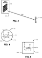
- the reader 310 may include a circularly polarized RFID reader antenna 320.
- the electric field of the electromagnetic wave radiated by a circularly polarized antenna rotates as a function of time.
- the linearly polarized antenna 240 of the RFID device 120 may be read by the circularly polarized antenna of the RFID reader 310 irrespective of the orientation of the RFID device 120.
- the RFID device 120 When interrogated by the RFID reader 310, the RFID device 120 communicates tool information 222 to the reader 310.
- the communications may be bi-directional, whereby the RFID reader 310 may also send data to the RFID device 120.
- Locating the RFID device 120 within the tool portion 114 offers certain advantages. Whereas RFID devices mounted on an outer surface of a tool can hinder the tool performance, the RFID device 120 does not hinder tool performance. Further, the RFID device 120 is protected from environmental effects and wear and tear due to handling. It is also protected against tampering. Still further, the RFID device 120 will not fall off the tool 110 and become lost.
- Locating the RFID device 120 within the dielectric inclusion 112 provides a significant advantage.
- the antennas of the RFID reader 310 and the RFID device 120 as two ports of a two port network.
- S21 is a measure of coupling between the two antennas. The applicants have conducted tests and found that the S21 coupling for an RFID device 120 within an air box (a type of dielectric inclusion 112) of the tool 110 is substantially higher than the S21 coupling for an RFID device that is simply embedded within a tool.
- Locating the RFID device 120 within the dielectric inclusion 112 substantially extends communications range of the RFID device 120. Consequently, communications between the RFID device 120 and the RFID reader 310 may be performed over greater distances.
- the extended range is especially advantageous for factories having very large floor areas and a large number of portable tools, as it makes tool tracking more feasible. A fewer number of RFID readers 310 would be needed to communicate with a large plurality of RFID devices 120.
- FIG 4 illustrates a tool 110 including a tool body 410 having a cylindrical shape.
- the tool body 410 may be a tool handle.
- the tool body 410 has a solid portion 412 and a dielectric inclusion 414.
- the dielectric inclusion 414 is not limited to any particular geometry, it may have the geometry of a rectangular prism.
- An RFID device 120 is attached to an inner wall defining the dielectric inclusion 414 and extends in an axial direction.
- the RFID device 120 may be attached to the surface using an adhesive or fasteners.
- the dielectric inclusion 414 may include a dielectric medium having a lower permitivity than the material of the solid portion 412.
- the solid portion 412 may be made of polytetrafluoroethylene (PTFE), and the inclusion medium may be air.
- the inclusion medium may be a liquid material that solidifies naturally or with thermal treatment. The solidified liquid may help in securing the RFID device 120 within the dielectric inclusion 414.
- the dielectric inclusion 414 has a length (not illustrated), width (w) and thickness (t).
- the dielectric inclusion 414 is positioned at a distance (d) from the surface of tool body 410.
- the distance (d) to the surface and the thickness (t) of the dielectric inclusion 414 are chosen such that due to constructive interference the electromagnetic field enhancement occurs.
- the applicants have observed for a dielectric inclusion medium of air and a cylindrical tool body 410 made of PTFE and having a diamater of 32 mm, the field enhancement occurs for d greater than 6 mm when t is equal to 9 mm. If t is reduced to 4 mm, the field enhancement occurs if d is greater than 5 mm. It is observed that as t increases, the minimum value of d that achieves field enhancement also increases. Other combinations of t and d may result in field enhancement. Electromagnetic analysis and measurements may be used to identify these combinations.
- Figure 5 illustrates another example of a tool 110.
- the tool 110 of Figure 5 includes a tool body 510 in the shape of a rectangular prism and a dielectric inclusion 512 also in the shape of a rectangular prism.
- An RFID device 120 is mounted to an inner wall of the tool body 510 and extends in an axial direction.
- the applicants observed field enhancement for d> 6 mm.
- t was reduced to 7 mm
- the observed field enhancement was observed for d> 5 mm.
- Further reducing t to 5 mm resulted in a range of 5 mm ⁇ d ⁇ 11 mm for which field enhancement was observed.
- the field enhancement occurred for 3 mm ⁇ d ⁇ 8 mm.
- the applicants have observed field enhancement beyond a specific value of d.
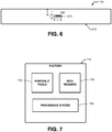
- Figure 6 illustrates another example of a tool 110.
- the tool 120 of Figure 6 includes a body 610 having a planar shape and a dielectric inclusion 612 extending along a plane of the tool body 610.
- FIG. 7 illustrates a factory 710 for producing a complex system.
- the factory 710 includes a large plurality of production tools at various locations within the factory 710.
- the production tools may be used to fabricate parts from raw materials, assemble parts and assemblies into larger assemblies, etc.
- a factory 710 for producing commercial aircraft may include thousands of high-precision tools dispersed over millions of square feet.
- the production tools may include tools (e.g., milling machines) that are fixed to a location in the factory 710.
- the production tools may also include portable tools 720, which may be moved from location to location within the factory 710. At least some of the portable production tools 720 have dielectric inclusions and RFID devices within the dielectric inclusions as described herein.
- the RFID devices may store and communicate information about their tools (e.g., tool identification number, tool characteristics, job identifier).
- the factory 710 further includes a plurality of RFID readers 730 distributed about the facility.
- Each RFID reader 730 is programmed to interrogate RFID devices.
- a fewer number of readers 730 may be distributed about the factor 710, and still be able to communicate with all of the RFID devices.
- RFID readers 730 may be placed at select locations, such as dock doors, work stations, tool cribs, etc.
- Information detected by the RFID readers 730 may be forwarded to a processing system 740.
- the processing system 740 tracks the locations of the portable tools 720 and ensures that the portable tools720 are being used on the correct job. Consequently, the processing system 740 can prevent tools from being left behind in an assembly by accident.
- the processing system 740 may also prevent tools from being removed from the factory, and it can manage the inventory of tools.
- the processing system 740 may also ensure that the tools are properly calibrated. For instance, an RFID tag could indicate the last date of calibration by an instrument laboratory. The processing system 740 may use that information to determine when a portable tool 720 should be recalibrated.
- Information detected by the RFID readers 730 may be forwarded to a processing system 740.
- the processing system 740 collects unique ID signals transmitted from the RFID readers 730 using software middleware that interfaces to the readers 730. This detection is performed continuously in real time.
- the processing system 740 may match the unique ID information to an asset name and send this data to other integration processors such as an enterprise resource planning (ERP) database.
- ERP enterprise resource planning
- the processing system 740 tracks the locations of the portable tools 720 and sends this information to electronic work instructions within manufacturing execution system to verify portable tools720 are being used on the correct job. Consequently, the processing system 740 may provide critical information to prevent wrong tools used on the jobs and establishes traceability from the tool unique ID to the job ID for facilitating tool utilization so they are not left behind in an assembly by accident. The processing system 740 may also prevent tools from being removed from the factory by linking the tool ID to a mechanic badge ID, and it can manage the inventory of tools.
- the processing system 740 may also ensure that the tools are properly calibrated. For instance, an RFID device indicates the last date of calibration by an instrument laboratory. The processing system 740 may use that information to determine when a portable tool 720 should be recalibrated. The processing system 740 sends the calibrated tool's unique ID to a metrology system database. This database maintains the reference to the tool calibration expiration date. If a calibrated tool approaches the expiration date, an electronic alert notice is sent out to the tool custodian to return the tool to the calibration certification laboratory. If the custodian forgets to follow this message and the tool is accidently used in a production process, the RFID device can be traced from the processing system and its associated work instruction system to facilitate the auditing process and rectify the error.
Landscapes
- Engineering & Computer Science (AREA)
- Computer Hardware Design (AREA)
- Microelectronics & Electronic Packaging (AREA)
- Physics & Mathematics (AREA)
- General Physics & Mathematics (AREA)
- Theoretical Computer Science (AREA)
- Portable Power Tools In General (AREA)
- General Factory Administration (AREA)
- Inorganic Insulating Materials (AREA)
Claims (7)
- Appareil comprenant un outil de production portable (110) comportant une inclusion diélectrique (112), une partie de diélectrique solide (412) et un dispositif RFID (120) ; dans lequel le dispositif RFID (120) est monté à l'intérieur de l'inclusion diélectrique (112) ;
caractérisé en ce que
l'inclusion diélectrique (112) est entièrement dans la partie solide (412) ; et
le dispositif RFID (120) comprend une antenne linéairement polarisée (240). - Appareil selon la revendication 1, dans lequel la partie solide (412) fait partie d'un manche d'outil.
- Appareil selon les revendications 1 ou 2, dans lequel l'inclusion diélectrique (112) comprend de l'air.
- Appareil selon l'une quelconque des revendications précédentes, dans lequel l'inclusion diélectrique (112) a une permittivité égale à l'unité.
- Appareil selon l'une quelconque des revendications 1 à 4, dans lequel le dispositif RFID (120) est fixé à la partie solide (412) au niveau d'une paroi (116) définissant l'inclusion diélectrique (112).
- Appareil selon la revendication 5, dans lequel un milieu d'inclusion remplit un espace entre le dispositif RFID (120) et les autres parois (116) définissant l'inclusion diélectrique (112).
- Appareil selon l'une quelconque des revendications 1 à 6, dans lequel l'inclusion diélectrique (112) est configurée pour créer une discontinuité dans la partie d'outil (114), qui amène les ondes électromagnétiques incidentes sur l'outil (110) à créer des ondes incidentes et réfléchies, les ondes subissant une interférence constructive.
Applications Claiming Priority (1)
| Application Number | Priority Date | Filing Date | Title |
|---|---|---|---|
| US13/539,432 US9898698B2 (en) | 2011-07-01 | 2012-06-30 | Production tool having RFID device mounted within a dielectric inclusion |
Publications (3)
| Publication Number | Publication Date |
|---|---|
| EP2680200A2 EP2680200A2 (fr) | 2014-01-01 |
| EP2680200A3 EP2680200A3 (fr) | 2015-08-12 |
| EP2680200B1 true EP2680200B1 (fr) | 2019-10-16 |
Family
ID=48747898
Family Applications (1)
| Application Number | Title | Priority Date | Filing Date |
|---|---|---|---|
| EP13171917.1A Active EP2680200B1 (fr) | 2012-06-30 | 2013-06-13 | Outil de fabrication comportant un dispositif RFID monté à l'intérieur d'une inclusion diélectrique |
Country Status (4)
| Country | Link |
|---|---|
| EP (1) | EP2680200B1 (fr) |
| JP (1) | JP6602524B2 (fr) |
| KR (1) | KR102067839B1 (fr) |
| CA (1) | CA2815864C (fr) |
Families Citing this family (4)
| Publication number | Priority date | Publication date | Assignee | Title |
|---|---|---|---|---|
| WO2016189638A1 (fr) * | 2015-05-26 | 2016-12-01 | 株式会社エニイワイヤ | Système de gestion de tournevis électrique |
| DE102015120153A1 (de) * | 2015-11-20 | 2017-05-24 | Bilz Werkzeugfabrik Gmbh & Co. Kg | Werkzeug mit RFID-Chip und Verfahren zum Befestigen eines solchen an einem Werkzeug |
| FR3087689A1 (fr) * | 2018-10-30 | 2020-05-01 | Airbus Operations (S.A.S.) | Systeme et procede de fabrication pour un atelier de fabrication d’equipements. |
| AT522384B1 (de) * | 2019-04-09 | 2021-05-15 | Digi Gebau Gmbh | Arbeitsgerät und verfahren zur erfassung eines arbeitsgeräts |
Family Cites Families (21)
| Publication number | Priority date | Publication date | Assignee | Title |
|---|---|---|---|---|
| US4742470A (en) * | 1985-12-30 | 1988-05-03 | Gte Valeron Corporation | Tool identification system |
| US5142128A (en) * | 1990-05-04 | 1992-08-25 | Perkin Gregg S | Oilfield equipment identification apparatus |
| DE4425736C2 (de) * | 1994-07-21 | 1997-12-18 | Micro Sensys Gmbh | Einbauschale für Daten- oder Codeträger |
| JP3035287U (ja) * | 1996-08-31 | 1997-03-11 | 西日本メタルワーク株式会社 | システム作業台 |
| JP2002183695A (ja) * | 2000-12-18 | 2002-06-28 | Hanex Co Ltd | Rfidタグ構造体及びその取付構造 |
| US20030156033A1 (en) * | 2001-01-12 | 2003-08-21 | Paul C. Koomey | Apparatus and method for assembly, retention and physical protection of radio frequency identification tags for oil drill strings |
| DE10145413A1 (de) * | 2001-09-14 | 2005-06-09 | Focke Gmbh & Co. Kg | Verfahren zum Identifizieren von Gegenständen sowie Gegenstand mit elektronischem Datenträger |
| US20030102970A1 (en) * | 2001-11-15 | 2003-06-05 | Creel Myron Dale | Tool or implement storage system using wireless devices to facilitate tool control |
| JP2004234484A (ja) | 2003-01-31 | 2004-08-19 | Toshiba It & Control Systems Corp | 作業管理方法及びシステム並びに該システムで用いる工具 |
| JP2005207167A (ja) * | 2004-01-26 | 2005-08-04 | Toppan Printing Co Ltd | Rf−id読み取り機能付き工具箱及びrf−idタグ付き工具 |
| JP2006042059A (ja) | 2004-07-28 | 2006-02-09 | Tdk Corp | 無線通信装置及びそのインピ−ダンス調整方法 |
| JP4477961B2 (ja) * | 2004-07-28 | 2010-06-09 | 株式会社日立製作所 | Icタグ付きボルト |
| US7253736B2 (en) * | 2004-08-26 | 2007-08-07 | Sdgi Holdings, Inc. | RFID tag for instrument handles |
| JP2006142402A (ja) * | 2004-11-17 | 2006-06-08 | Hitachi Koki Co Ltd | 携帯工具 |
| JP4764000B2 (ja) * | 2004-12-03 | 2011-08-31 | 株式会社富士通エフサス | 工具等管理システム |
| US7315248B2 (en) | 2005-05-13 | 2008-01-01 | 3M Innovative Properties Company | Radio frequency identification tags for use on metal or other conductive objects |
| US20080129453A1 (en) | 2006-11-30 | 2008-06-05 | Symbol Technologies, Inc. | Method, system, and apparatus for a radio frequency identification (RFID) waveguide for reading items in a stack |
| US20080303633A1 (en) * | 2007-06-07 | 2008-12-11 | The Hong Kong University Of Science And Technology | High gain rfid tag antennas |
| JP5239499B2 (ja) * | 2008-05-13 | 2013-07-17 | 戸田工業株式会社 | 複合磁性体アンテナ及びrfタグ、該複合磁性体アンテナ又はrfタグを設置した金属部品、金属工具 |
| JP5355472B2 (ja) | 2009-12-10 | 2013-11-27 | ニッタ株式会社 | 情報記憶媒体、管理対象物品および管理システム |
| US9898698B2 (en) * | 2011-07-01 | 2018-02-20 | The Boeing Company | Production tool having RFID device mounted within a dielectric inclusion |
-
2013
- 2013-05-14 KR KR1020130054235A patent/KR102067839B1/ko active IP Right Grant
- 2013-05-14 CA CA2815864A patent/CA2815864C/fr active Active
- 2013-06-13 EP EP13171917.1A patent/EP2680200B1/fr active Active
- 2013-06-28 JP JP2013136136A patent/JP6602524B2/ja active Active
Non-Patent Citations (1)
| Title |
|---|
| None * |
Also Published As
| Publication number | Publication date |
|---|---|
| KR20140002482A (ko) | 2014-01-08 |
| CA2815864A1 (fr) | 2013-12-30 |
| EP2680200A2 (fr) | 2014-01-01 |
| JP6602524B2 (ja) | 2019-11-06 |
| KR102067839B1 (ko) | 2020-01-17 |
| JP2014013568A (ja) | 2014-01-23 |
| CA2815864C (fr) | 2018-04-17 |
| EP2680200A3 (fr) | 2015-08-12 |
Similar Documents
| Publication | Publication Date | Title |
|---|---|---|
| Velandia et al. | Towards industrial internet of things: Crankshaft monitoring, traceability and tracking using RFID | |
| EP2680200B1 (fr) | Outil de fabrication comportant un dispositif RFID monté à l'intérieur d'une inclusion diélectrique | |
| CN103217944B (zh) | 包括集成近场通信接口的资产数据模块 | |
| EP1846873B1 (fr) | Dispositif intelligent possedant un transpondeur radiofrequence passif encastre dans le metal et exemples d'utilisation | |
| EP3930958B1 (fr) | Système de surveillance sans fil et passive de contrainte pendant des processus de fabrication | |
| US9955450B2 (en) | Geo-localization assembly and methodology | |
| KR20170038879A (ko) | 공장에서 모니터링될 대상의 재고를 검출하기 위한 시스템 | |
| JP7150995B2 (ja) | 専用rfidタグを使用してタイヤ製造中の自動品質管理を維持するためのシステムおよび方法 | |
| JP2006208387A (ja) | 情報技術(it)機器測位システム | |
| US20100289626A1 (en) | Radio frequency identification (rfid) enabled inventory tray | |
| WO2011046631A1 (fr) | Étiquette rfid montée en bordure | |
| JP5355472B2 (ja) | 情報記憶媒体、管理対象物品および管理システム | |
| US9898698B2 (en) | Production tool having RFID device mounted within a dielectric inclusion | |
| US9076095B2 (en) | Extendable identification tag | |
| US7541927B2 (en) | Wireless real time location system (RTLS) using audible and/or visible signals | |
| US20150154433A1 (en) | Rfid molded connector tracking system and method | |
| JP2002049900A (ja) | 電磁誘導タグを利用した物品の管理方法及び電磁誘導タグを利用した物品の管理システム | |
| CN102023296A (zh) | Rfid定位方法及其系统 | |
| US9803444B2 (en) | Obtaining data from an underwater component | |
| JP6025046B2 (ja) | Rfidタグ及びrfidシステム | |
| Happonen et al. | Radio identification in construction industry case: Tagging hollow steel beams | |
| CN116008907A (zh) | 射频识别标签定位系统、方法、装置及存储介质 | |
| Ko et al. | RFID Object Tracking in Civil Engineering: An Academic | |
| Richards | location location location |
Legal Events
| Date | Code | Title | Description |
|---|---|---|---|
| PUAI | Public reference made under article 153(3) epc to a published international application that has entered the european phase |
Free format text: ORIGINAL CODE: 0009012 |
|
| 17P | Request for examination filed |
Effective date: 20130613 |
|
| AK | Designated contracting states |
Kind code of ref document: A2 Designated state(s): AL AT BE BG CH CY CZ DE DK EE ES FI FR GB GR HR HU IE IS IT LI LT LU LV MC MK MT NL NO PL PT RO RS SE SI SK SM TR |
|
| AX | Request for extension of the european patent |
Extension state: BA ME |
|
| RIC1 | Information provided on ipc code assigned before grant |
Ipc: G06Q 10/06 20120101ALI20150323BHEP Ipc: G06Q 10/10 20120101AFI20150323BHEP Ipc: G06K 19/077 20060101ALI20150323BHEP |
|
| PUAL | Search report despatched |
Free format text: ORIGINAL CODE: 0009013 |
|
| AK | Designated contracting states |
Kind code of ref document: A3 Designated state(s): AL AT BE BG CH CY CZ DE DK EE ES FI FR GB GR HR HU IE IS IT LI LT LU LV MC MK MT NL NO PL PT RO RS SE SI SK SM TR |
|
| AX | Request for extension of the european patent |
Extension state: BA ME |
|
| RIC1 | Information provided on ipc code assigned before grant |
Ipc: G06Q 10/06 20120101ALI20150708BHEP Ipc: G06K 19/077 20060101ALI20150708BHEP Ipc: G06Q 10/10 20120101AFI20150708BHEP |
|
| 17Q | First examination report despatched |
Effective date: 20160613 |
|
| STAA | Information on the status of an ep patent application or granted ep patent |
Free format text: STATUS: EXAMINATION IS IN PROGRESS |
|
| GRAP | Despatch of communication of intention to grant a patent |
Free format text: ORIGINAL CODE: EPIDOSNIGR1 |
|
| STAA | Information on the status of an ep patent application or granted ep patent |
Free format text: STATUS: GRANT OF PATENT IS INTENDED |
|
| INTG | Intention to grant announced |
Effective date: 20190318 |
|
| GRAS | Grant fee paid |
Free format text: ORIGINAL CODE: EPIDOSNIGR3 |
|
| GRAA | (expected) grant |
Free format text: ORIGINAL CODE: 0009210 |
|
| STAA | Information on the status of an ep patent application or granted ep patent |
Free format text: STATUS: THE PATENT HAS BEEN GRANTED |
|
| AK | Designated contracting states |
Kind code of ref document: B1 Designated state(s): AL AT BE BG CH CY CZ DE DK EE ES FI FR GB GR HR HU IE IS IT LI LT LU LV MC MK MT NL NO PL PT RO RS SE SI SK SM TR |
|
| REG | Reference to a national code |
Ref country code: GB Ref legal event code: FG4D |
|
| REG | Reference to a national code |
Ref country code: CH Ref legal event code: EP |
|
| REG | Reference to a national code |
Ref country code: DE Ref legal event code: R096 Ref document number: 602013061720 Country of ref document: DE |
|
| REG | Reference to a national code |
Ref country code: IE Ref legal event code: FG4D |
|
| REG | Reference to a national code |
Ref country code: AT Ref legal event code: REF Ref document number: 1192012 Country of ref document: AT Kind code of ref document: T Effective date: 20191115 |
|
| REG | Reference to a national code |
Ref country code: DE Ref legal event code: R082 Ref document number: 602013061720 Country of ref document: DE Representative=s name: MAIER, LL.M., MICHAEL C., DE Ref country code: DE Ref legal event code: R082 Ref document number: 602013061720 Country of ref document: DE Representative=s name: BOULT WADE TENNANT LLP, DE |
|
| REG | Reference to a national code |
Ref country code: DE Ref legal event code: R082 Ref document number: 602013061720 Country of ref document: DE Representative=s name: BOULT WADE TENNANT LLP, DE |
|
| REG | Reference to a national code |
Ref country code: NL Ref legal event code: MP Effective date: 20191016 |
|
| REG | Reference to a national code |
Ref country code: LT Ref legal event code: MG4D |
|
| REG | Reference to a national code |
Ref country code: AT Ref legal event code: MK05 Ref document number: 1192012 Country of ref document: AT Kind code of ref document: T Effective date: 20191016 |
|
| PG25 | Lapsed in a contracting state [announced via postgrant information from national office to epo] |
Ref country code: NL Free format text: LAPSE BECAUSE OF FAILURE TO SUBMIT A TRANSLATION OF THE DESCRIPTION OR TO PAY THE FEE WITHIN THE PRESCRIBED TIME-LIMIT Effective date: 20191016 Ref country code: AT Free format text: LAPSE BECAUSE OF FAILURE TO SUBMIT A TRANSLATION OF THE DESCRIPTION OR TO PAY THE FEE WITHIN THE PRESCRIBED TIME-LIMIT Effective date: 20191016 Ref country code: LT Free format text: LAPSE BECAUSE OF FAILURE TO SUBMIT A TRANSLATION OF THE DESCRIPTION OR TO PAY THE FEE WITHIN THE PRESCRIBED TIME-LIMIT Effective date: 20191016 Ref country code: PL Free format text: LAPSE BECAUSE OF FAILURE TO SUBMIT A TRANSLATION OF THE DESCRIPTION OR TO PAY THE FEE WITHIN THE PRESCRIBED TIME-LIMIT Effective date: 20191016 Ref country code: GR Free format text: LAPSE BECAUSE OF FAILURE TO SUBMIT A TRANSLATION OF THE DESCRIPTION OR TO PAY THE FEE WITHIN THE PRESCRIBED TIME-LIMIT Effective date: 20200117 Ref country code: FI Free format text: LAPSE BECAUSE OF FAILURE TO SUBMIT A TRANSLATION OF THE DESCRIPTION OR TO PAY THE FEE WITHIN THE PRESCRIBED TIME-LIMIT Effective date: 20191016 Ref country code: BG Free format text: LAPSE BECAUSE OF FAILURE TO SUBMIT A TRANSLATION OF THE DESCRIPTION OR TO PAY THE FEE WITHIN THE PRESCRIBED TIME-LIMIT Effective date: 20200116 Ref country code: NO Free format text: LAPSE BECAUSE OF FAILURE TO SUBMIT A TRANSLATION OF THE DESCRIPTION OR TO PAY THE FEE WITHIN THE PRESCRIBED TIME-LIMIT Effective date: 20200116 Ref country code: LV Free format text: LAPSE BECAUSE OF FAILURE TO SUBMIT A TRANSLATION OF THE DESCRIPTION OR TO PAY THE FEE WITHIN THE PRESCRIBED TIME-LIMIT Effective date: 20191016 Ref country code: SE Free format text: LAPSE BECAUSE OF FAILURE TO SUBMIT A TRANSLATION OF THE DESCRIPTION OR TO PAY THE FEE WITHIN THE PRESCRIBED TIME-LIMIT Effective date: 20191016 Ref country code: PT Free format text: LAPSE BECAUSE OF FAILURE TO SUBMIT A TRANSLATION OF THE DESCRIPTION OR TO PAY THE FEE WITHIN THE PRESCRIBED TIME-LIMIT Effective date: 20200217 Ref country code: ES Free format text: LAPSE BECAUSE OF FAILURE TO SUBMIT A TRANSLATION OF THE DESCRIPTION OR TO PAY THE FEE WITHIN THE PRESCRIBED TIME-LIMIT Effective date: 20191016 |
|
| PG25 | Lapsed in a contracting state [announced via postgrant information from national office to epo] |
Ref country code: IS Free format text: LAPSE BECAUSE OF FAILURE TO SUBMIT A TRANSLATION OF THE DESCRIPTION OR TO PAY THE FEE WITHIN THE PRESCRIBED TIME-LIMIT Effective date: 20200224 Ref country code: HR Free format text: LAPSE BECAUSE OF FAILURE TO SUBMIT A TRANSLATION OF THE DESCRIPTION OR TO PAY THE FEE WITHIN THE PRESCRIBED TIME-LIMIT Effective date: 20191016 Ref country code: RS Free format text: LAPSE BECAUSE OF FAILURE TO SUBMIT A TRANSLATION OF THE DESCRIPTION OR TO PAY THE FEE WITHIN THE PRESCRIBED TIME-LIMIT Effective date: 20191016 |
|
| PG25 | Lapsed in a contracting state [announced via postgrant information from national office to epo] |
Ref country code: AL Free format text: LAPSE BECAUSE OF FAILURE TO SUBMIT A TRANSLATION OF THE DESCRIPTION OR TO PAY THE FEE WITHIN THE PRESCRIBED TIME-LIMIT Effective date: 20191016 |
|
| REG | Reference to a national code |
Ref country code: DE Ref legal event code: R097 Ref document number: 602013061720 Country of ref document: DE |
|
| PG2D | Information on lapse in contracting state deleted |
Ref country code: IS |
|
| PG25 | Lapsed in a contracting state [announced via postgrant information from national office to epo] |
Ref country code: RO Free format text: LAPSE BECAUSE OF FAILURE TO SUBMIT A TRANSLATION OF THE DESCRIPTION OR TO PAY THE FEE WITHIN THE PRESCRIBED TIME-LIMIT Effective date: 20191016 Ref country code: CZ Free format text: LAPSE BECAUSE OF FAILURE TO SUBMIT A TRANSLATION OF THE DESCRIPTION OR TO PAY THE FEE WITHIN THE PRESCRIBED TIME-LIMIT Effective date: 20191016 Ref country code: EE Free format text: LAPSE BECAUSE OF FAILURE TO SUBMIT A TRANSLATION OF THE DESCRIPTION OR TO PAY THE FEE WITHIN THE PRESCRIBED TIME-LIMIT Effective date: 20191016 Ref country code: DK Free format text: LAPSE BECAUSE OF FAILURE TO SUBMIT A TRANSLATION OF THE DESCRIPTION OR TO PAY THE FEE WITHIN THE PRESCRIBED TIME-LIMIT Effective date: 20191016 Ref country code: IS Free format text: LAPSE BECAUSE OF FAILURE TO SUBMIT A TRANSLATION OF THE DESCRIPTION OR TO PAY THE FEE WITHIN THE PRESCRIBED TIME-LIMIT Effective date: 20200216 |
|
| PLBE | No opposition filed within time limit |
Free format text: ORIGINAL CODE: 0009261 |
|
| STAA | Information on the status of an ep patent application or granted ep patent |
Free format text: STATUS: NO OPPOSITION FILED WITHIN TIME LIMIT |
|
| PG25 | Lapsed in a contracting state [announced via postgrant information from national office to epo] |
Ref country code: IT Free format text: LAPSE BECAUSE OF FAILURE TO SUBMIT A TRANSLATION OF THE DESCRIPTION OR TO PAY THE FEE WITHIN THE PRESCRIBED TIME-LIMIT Effective date: 20191016 Ref country code: SK Free format text: LAPSE BECAUSE OF FAILURE TO SUBMIT A TRANSLATION OF THE DESCRIPTION OR TO PAY THE FEE WITHIN THE PRESCRIBED TIME-LIMIT Effective date: 20191016 Ref country code: SM Free format text: LAPSE BECAUSE OF FAILURE TO SUBMIT A TRANSLATION OF THE DESCRIPTION OR TO PAY THE FEE WITHIN THE PRESCRIBED TIME-LIMIT Effective date: 20191016 |
|
| 26N | No opposition filed |
Effective date: 20200717 |
|
| PG25 | Lapsed in a contracting state [announced via postgrant information from national office to epo] |
Ref country code: SI Free format text: LAPSE BECAUSE OF FAILURE TO SUBMIT A TRANSLATION OF THE DESCRIPTION OR TO PAY THE FEE WITHIN THE PRESCRIBED TIME-LIMIT Effective date: 20191016 |
|
| PG25 | Lapsed in a contracting state [announced via postgrant information from national office to epo] |
Ref country code: MC Free format text: LAPSE BECAUSE OF FAILURE TO SUBMIT A TRANSLATION OF THE DESCRIPTION OR TO PAY THE FEE WITHIN THE PRESCRIBED TIME-LIMIT Effective date: 20191016 |
|
| REG | Reference to a national code |
Ref country code: CH Ref legal event code: PL |
|
| PG25 | Lapsed in a contracting state [announced via postgrant information from national office to epo] |
Ref country code: LU Free format text: LAPSE BECAUSE OF NON-PAYMENT OF DUE FEES Effective date: 20200613 |
|
| REG | Reference to a national code |
Ref country code: BE Ref legal event code: MM Effective date: 20200630 |
|
| PG25 | Lapsed in a contracting state [announced via postgrant information from national office to epo] |
Ref country code: LI Free format text: LAPSE BECAUSE OF NON-PAYMENT OF DUE FEES Effective date: 20200630 Ref country code: IE Free format text: LAPSE BECAUSE OF NON-PAYMENT OF DUE FEES Effective date: 20200613 Ref country code: CH Free format text: LAPSE BECAUSE OF NON-PAYMENT OF DUE FEES Effective date: 20200630 |
|
| PG25 | Lapsed in a contracting state [announced via postgrant information from national office to epo] |
Ref country code: BE Free format text: LAPSE BECAUSE OF NON-PAYMENT OF DUE FEES Effective date: 20200630 |
|
| PG25 | Lapsed in a contracting state [announced via postgrant information from national office to epo] |
Ref country code: TR Free format text: LAPSE BECAUSE OF FAILURE TO SUBMIT A TRANSLATION OF THE DESCRIPTION OR TO PAY THE FEE WITHIN THE PRESCRIBED TIME-LIMIT Effective date: 20191016 Ref country code: MT Free format text: LAPSE BECAUSE OF FAILURE TO SUBMIT A TRANSLATION OF THE DESCRIPTION OR TO PAY THE FEE WITHIN THE PRESCRIBED TIME-LIMIT Effective date: 20191016 Ref country code: CY Free format text: LAPSE BECAUSE OF FAILURE TO SUBMIT A TRANSLATION OF THE DESCRIPTION OR TO PAY THE FEE WITHIN THE PRESCRIBED TIME-LIMIT Effective date: 20191016 |
|
| PG25 | Lapsed in a contracting state [announced via postgrant information from national office to epo] |
Ref country code: MK Free format text: LAPSE BECAUSE OF FAILURE TO SUBMIT A TRANSLATION OF THE DESCRIPTION OR TO PAY THE FEE WITHIN THE PRESCRIBED TIME-LIMIT Effective date: 20191016 |
|
| P01 | Opt-out of the competence of the unified patent court (upc) registered |
Effective date: 20230516 |
|
| PGFP | Annual fee paid to national office [announced via postgrant information from national office to epo] |
Ref country code: FR Payment date: 20230626 Year of fee payment: 11 Ref country code: DE Payment date: 20230626 Year of fee payment: 11 |
|
| PGFP | Annual fee paid to national office [announced via postgrant information from national office to epo] |
Ref country code: GB Payment date: 20230627 Year of fee payment: 11 |