EP2679979A1 - Kratztester für Glasscheiben - Google Patents
Kratztester für Glasscheiben Download PDFInfo
- Publication number
- EP2679979A1 EP2679979A1 EP12173369.5A EP12173369A EP2679979A1 EP 2679979 A1 EP2679979 A1 EP 2679979A1 EP 12173369 A EP12173369 A EP 12173369A EP 2679979 A1 EP2679979 A1 EP 2679979A1
- Authority
- EP
- European Patent Office
- Prior art keywords
- scratch tester
- tester according
- sliding block
- spring
- cylinder
- Prior art date
- Legal status (The legal status is an assumption and is not a legal conclusion. Google has not performed a legal analysis and makes no representation as to the accuracy of the status listed.)
- Granted
Links
- 239000011521 glass Substances 0.000 title claims abstract description 68
- 238000006748 scratching Methods 0.000 claims abstract description 35
- 230000002393 scratching effect Effects 0.000 claims abstract description 35
- 239000010432 diamond Substances 0.000 claims abstract description 29
- 238000000034 method Methods 0.000 claims abstract description 15
- 229910003460 diamond Inorganic materials 0.000 claims description 25
- 125000006850 spacer group Chemical group 0.000 claims description 16
- XEEYBQQBJWHFJM-UHFFFAOYSA-N Iron Chemical compound [Fe] XEEYBQQBJWHFJM-UHFFFAOYSA-N 0.000 claims description 10
- 229910052751 metal Inorganic materials 0.000 claims description 7
- 239000002184 metal Substances 0.000 claims description 7
- 238000007790 scraping Methods 0.000 claims description 7
- PXHVJJICTQNCMI-UHFFFAOYSA-N Nickel Chemical compound [Ni] PXHVJJICTQNCMI-UHFFFAOYSA-N 0.000 claims description 6
- 229910052742 iron Inorganic materials 0.000 claims description 5
- VYZAMTAEIAYCRO-UHFFFAOYSA-N Chromium Chemical compound [Cr] VYZAMTAEIAYCRO-UHFFFAOYSA-N 0.000 claims description 3
- RTAQQCXQSZGOHL-UHFFFAOYSA-N Titanium Chemical compound [Ti] RTAQQCXQSZGOHL-UHFFFAOYSA-N 0.000 claims description 3
- 239000000956 alloy Substances 0.000 claims description 3
- 229910045601 alloy Inorganic materials 0.000 claims description 3
- 229910052782 aluminium Inorganic materials 0.000 claims description 3
- XAGFODPZIPBFFR-UHFFFAOYSA-N aluminium Chemical compound [Al] XAGFODPZIPBFFR-UHFFFAOYSA-N 0.000 claims description 3
- 229910052804 chromium Inorganic materials 0.000 claims description 3
- 239000011651 chromium Substances 0.000 claims description 3
- 229910017052 cobalt Inorganic materials 0.000 claims description 3
- 239000010941 cobalt Substances 0.000 claims description 3
- GUTLYIVDDKVIGB-UHFFFAOYSA-N cobalt atom Chemical compound [Co] GUTLYIVDDKVIGB-UHFFFAOYSA-N 0.000 claims description 3
- 229910052759 nickel Inorganic materials 0.000 claims description 3
- 239000010936 titanium Substances 0.000 claims description 3
- 229910052719 titanium Inorganic materials 0.000 claims description 3
- WFKWXMTUELFFGS-UHFFFAOYSA-N tungsten Chemical compound [W] WFKWXMTUELFFGS-UHFFFAOYSA-N 0.000 claims description 3
- 229910052721 tungsten Inorganic materials 0.000 claims description 3
- 239000010937 tungsten Substances 0.000 claims description 3
- 229910052720 vanadium Inorganic materials 0.000 claims description 3
- LEONUFNNVUYDNQ-UHFFFAOYSA-N vanadium atom Chemical compound [V] LEONUFNNVUYDNQ-UHFFFAOYSA-N 0.000 claims description 3
- 238000012360 testing method Methods 0.000 description 15
- 239000000463 material Substances 0.000 description 7
- 238000005259 measurement Methods 0.000 description 6
- -1 polyethylene Polymers 0.000 description 5
- 229920000515 polycarbonate Polymers 0.000 description 3
- 239000004417 polycarbonate Substances 0.000 description 3
- 210000003746 feather Anatomy 0.000 description 2
- 239000000203 mixture Substances 0.000 description 2
- 229920000139 polyethylene terephthalate Polymers 0.000 description 2
- 239000005020 polyethylene terephthalate Substances 0.000 description 2
- 239000010935 stainless steel Substances 0.000 description 2
- 229910001220 stainless steel Inorganic materials 0.000 description 2
- 239000004575 stone Substances 0.000 description 2
- 238000010998 test method Methods 0.000 description 2
- 239000004952 Polyamide Substances 0.000 description 1
- 239000004698 Polyethylene Substances 0.000 description 1
- 239000004743 Polypropylene Substances 0.000 description 1
- 239000004793 Polystyrene Substances 0.000 description 1
- XECAHXYUAAWDEL-UHFFFAOYSA-N acrylonitrile butadiene styrene Chemical compound C=CC=C.C=CC#N.C=CC1=CC=CC=C1 XECAHXYUAAWDEL-UHFFFAOYSA-N 0.000 description 1
- 229920000122 acrylonitrile butadiene styrene Polymers 0.000 description 1
- 239000004676 acrylonitrile butadiene styrene Substances 0.000 description 1
- 230000001154 acute effect Effects 0.000 description 1
- 230000004888 barrier function Effects 0.000 description 1
- 238000000576 coating method Methods 0.000 description 1
- 239000002131 composite material Substances 0.000 description 1
- 229920001577 copolymer Polymers 0.000 description 1
- 230000001419 dependent effect Effects 0.000 description 1
- 238000011156 evaluation Methods 0.000 description 1
- 238000007373 indentation Methods 0.000 description 1
- 238000004519 manufacturing process Methods 0.000 description 1
- 230000035515 penetration Effects 0.000 description 1
- 239000004033 plastic Substances 0.000 description 1
- 229920003023 plastic Polymers 0.000 description 1
- 229920003229 poly(methyl methacrylate) Polymers 0.000 description 1
- 229920000058 polyacrylate Polymers 0.000 description 1
- 229920002647 polyamide Polymers 0.000 description 1
- 229920001707 polybutylene terephthalate Polymers 0.000 description 1
- 229920000728 polyester Polymers 0.000 description 1
- 229920000573 polyethylene Polymers 0.000 description 1
- 229920000642 polymer Polymers 0.000 description 1
- 229920001155 polypropylene Polymers 0.000 description 1
- 229920001296 polysiloxane Polymers 0.000 description 1
- 229920002223 polystyrene Polymers 0.000 description 1
- 229920002635 polyurethane Polymers 0.000 description 1
- 239000004814 polyurethane Substances 0.000 description 1
- 238000003825 pressing Methods 0.000 description 1
- 230000001681 protective effect Effects 0.000 description 1
- 230000000284 resting effect Effects 0.000 description 1
- HBMJWWWQQXIZIP-UHFFFAOYSA-N silicon carbide Chemical compound [Si+]#[C-] HBMJWWWQQXIZIP-UHFFFAOYSA-N 0.000 description 1
- 229910010271 silicon carbide Inorganic materials 0.000 description 1
- UONOETXJSWQNOL-UHFFFAOYSA-N tungsten carbide Chemical compound [W+]#[C-] UONOETXJSWQNOL-UHFFFAOYSA-N 0.000 description 1
- 210000004127 vitreous body Anatomy 0.000 description 1
Images

Classifications
-
- G—PHYSICS
- G01—MEASURING; TESTING
- G01N—INVESTIGATING OR ANALYSING MATERIALS BY DETERMINING THEIR CHEMICAL OR PHYSICAL PROPERTIES
- G01N3/00—Investigating strength properties of solid materials by application of mechanical stress
- G01N3/40—Investigating hardness or rebound hardness
- G01N3/42—Investigating hardness or rebound hardness by performing impressions under a steady load by indentors, e.g. sphere, pyramid
- G01N3/46—Investigating hardness or rebound hardness by performing impressions under a steady load by indentors, e.g. sphere, pyramid the indentors performing a scratching movement
Definitions
- the invention relates to a scratch tester for glass panes, a method for scratch testing of glass panes and the use of a scratch tester.
- Glass is generally in demand as a highly transparent and at the same time hard material. Despite its high surface hardness, glass is often a brittle and often fragile material. The durability, strength and stability of glass sheets is in many applications of great importance. Important areas are structural glazing, vehicle glazing, automotive glazing and photovoltaic glass. Due to its amorphous basic structure, the evaluation of the physical parameters is quite difficult with the material glass. At the same time glass panes are exposed to heavy loads in vehicles, especially at high speeds and centrifugal forces. Therefore, simple and well reproducible test procedures are of great importance for assessing this capacity. In particular, the ever increasing costs of glass breakage, for example by stone chipping, make a reproducible test procedure of the glass sheets necessary. The wheel test should refer to the strength of the entire windshield. It is about whether a (supposedly) small and partly barely visible scratch can lead to a windshield breakage.
- the scratch resistance of a glass can be determined by various methods and methods.
- various methods for determining the material hardness can be used, for example, the hardness determination according to Mohs, Martens, Brinell and Vickers.
- the methods mentioned here determine the forces and / or penetration depths acting on the glass surface. Due to the high surface hardness of the glass, only very hard materials are suitable for scratching glass. Suitable materials are, for example, silicon carbide and diamond.
- US2002014778 A1 discloses a method for protecting windshields of a motor vehicle against stone chipping.
- the protective effect is generated by a resistant barrier in the edge region of the disc.
- US 3,985,026 A discloses an apparatus for testing surface coatings on glassware.
- GB 2,449,174 A discloses an automotive glazing with printed circuits. Furthermore, a method for removing the imprint is disclosed. The method involves a scratch test with a Rockwell diamond and a force greater than 10 N.
- DE 10 2010 031 866 A1 discloses a silicone coated glass surface.
- a scratch test serves to determine the surface properties.
- the scratch test comprises a tungsten carbide tip with a weight of more than 500 g.
- the object of the invention is to provide a device which ensures a scoring of the glass surface and the near-surface glass body with a constant and reproducible force input, as well as an unchanging geometry of the scratch tip over many tests.
- the scratch tester comprises a scratch cylinder.
- the scratching cylinder is designed as a hollow cylinder and comprises a movably mounted within the scratching cylinder Feather.
- the spring is connected within the scratching cylinder with a holding block and a diamond attached to the holding block.
- the holding block can be designed in the form of several connected components.
- the holding block fixes the diamond attached to scratch the glass surface.
- the holding block is mounted vertically movable within the scratching cylinder.
- the scratching cylinder further comprises a recess or opening in the form of an adjusting window along the outer surface.
- the spring is loosely or firmly connected within the scratching cylinder in the region of the adjusting window with an adjusting device.
- the term "connected" in the sense of the invention comprises both a fixed connection with the spring and a loose connection in which the adjusting device or the holding block compresses the spring.
- the adjusting device is preferably designed as a screw-fastened metal ring.
- the scratch tester according to the invention for glass panes further comprises at least one sliding block with a throughbore and two slide rails located below the sliding block.
- the sliding block comprises metal, composite or plastic blocks, preferably made of iron, particularly preferably made of stainless steel.
- the sliding block allows safe guidance of the scratch tester according to the invention and prevents slipping.
- the scratching cylinder is fixed within the throughbore of the sliding block, for example with a screw or rivet.
- the scraper cylinder is preferably arranged perpendicular to the slide rails in the throughbore.
- the scratching cylinder may alternatively be arranged and fixed at an angle of 70 ° to 110 ° to the slide rails within the throughbore.
- the scratching cylinder is preferably fixed within the through hole via a locking screw.
- the locking screw allows a quick and easy replacement of the scraper cylinder so that the scraper tester can be used with different scraper cylinders.
- the simple and quick change of the scraping cylinder also allows the rapid examination of different types of glass sheet one behind the other.
- the holding block is preferably movably mounted within a guide ring.
- the guide ring allows the use of holding blocks whose diameter is smaller than the diameter of the scratching cylinder.
- the guide ring is preferably fixed on the locking screw.
- the diamond preferably includes diamond Vickers or diamonds with an acute angle cone shape.
- the diamond preferably has the shape of an equilateral pyramid in the region of its tip. This regular geometry allows a reproducible scratching of the glass surface. In case of deviations from the equilateral pyramidal shape of the diamond can be reground several times and thus recycled frequently and inexpensively. Both natural and artificial industrial diamonds are suitable.
- the sliding block preferably has a spacer in the direction of the slide rails.
- the spacer is preferably designed so that when the sliding block rests on the glass surface, it protrudes beyond the slide rails.
- the spacer creates a defined path or distance over which the scratch tester can be slid over the glass surface from the edge region. Another measuring device, for example a centimeter gauge, is not necessary.
- the spacer is preferably formed in section in the region of an end block T-shaped.
- the end block is preferably disk-shaped, the thickness of the end block is preferably 2 mm to 40 mm.
- the entire spacer preferably has a length of 20 mm to 150 mm.
- the distance of the diamond within the scraping cylinder to the glass edge is defined by the positioning of the throughbore within the pusher block. A resting of the diamond on the direct glass edge should be avoided, since the glass tensions in the direct edge range deviate quite clearly from the remaining disk surface. A measurement starting directly at the edge of the window would therefore falsify the measurement result in its entirety.
- the spring preferably contains a metal, more preferably aluminum, titanium, iron, chromium, vanadium, cobalt, nickel, tungsten and / or alloys thereof, particularly preferably piano wire.
- the sliding block and / or the scraping cylinder preferably contain a metal, more preferably aluminum, titanium, iron, chromium, vanadium, cobalt, nickel, tungsten and / or alloys thereof.
- the sliding block and the scraping cylinder in an alternative embodiment preferably contain a polymer, preferably polyethylene, polypropylene, polystyrene, polyurethanes, polymethylmethacrylates, polyacrylates, polyesters, polyamides, polyethylene terephthalate and / or mixtures or copolymers thereof, more preferably polycarbonate blends such as polycarboate / polyethylene terephthalate; Polycarbonate / acrylonitrile-butadiene-styrene; Polycarbonate / polybutylene terephthalate.
- a polymer preferably polyethylene, polypropylene, polystyrene, polyurethanes, polymethylmethacrylates, polyacrylates, polyesters, polyamides, polyethylene terephthalate and / or mixtures or copolymers thereof, more preferably polycarbonate blends such as polycarboate / polyethylene terephthalate; Polycarbonate / acrylonitrile-butadiene-styren
- the holding block preferably has a notch and the scratching cylinder on a locking screw.
- the indentation preferably includes the tip of the locking screw within the scratching cylinder.
- the holding block can move in this case only in the direction of stretching and stretching of the spring and along the notch. A movement of the holding block along its axis of rotation is only slightly possible. A tilting of the holding block and thus the diamond on the glass surface is thus avoided.
- the spring preferably exerts a force of 1 N to 20 N and preferably has a spring constant with a value of 2 N / m to 100 N / m, preferably 5 N / m to 50 N / m.
- the spring force depends essentially on the required test conditions and the glass surface to be examined. The range from 1 N to 20 N allows a reproducible scratching of the glass surface. Depending on the hardness of the glass surface and larger forces may be necessary.
- the diamond is preferably positioned with relaxed and tensioned spring between or below the slide rails. When the spring is tensioned, the diamond is positioned further below the slide rails, so that the diamond is positioned directly on the glass surface when the scratch tester is placed.
- the invention further comprises a method for defined scratching of a glass surface with a scratch tester according to the invention as described above.
- the spring is fixed via the adjustment device within the Justierfernsters.
- a defined force is transmitted from the spring to the holding block and thus to the diamond.
- a force equivalent to the spring force set via the adjusting device in the spring is exerted on the hand of a test person by applying the slide rails to rest on a spring Glass surface to be brought.
- the sliding block is moved over a preferably defined distance over the glass surface.
- the sliding block is preferably moved over the glass surface until it reaches the stop of a spacer fastened on the sliding block.
- the sliding block is brought to rest on the edge of the glass pane with the slide rails.
- the sliding block is moved in the opposite direction to the spacer until the spacer comes to rest on the edge of the glass pane.
- the spacer creates a defined path or distance over which the scratch tester can be slid over the glass surface from the edge region.
- the invention further includes the use of the scratch tester according to the invention for the defined scratching of glass panes, preferably vehicle windows, particularly preferably windscreens, side windows or rear windows.
- the scratch tester according to the invention allows a testing of the glass sheets directly at the production site. Elaborate, permanently installed test equipment is not necessary.
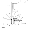
- FIG. 1 shows a cross section of the scratch tester (I) according to the invention.
- the scratch tester comprises a sliding block (2) with a throughbore (16). Two slide rails (3) are arranged below the sliding block (2).
- the sliding block (2) preferably comprises metal blocks, particularly preferably made of iron, particularly preferably of stainless steel.
- the scratch tester (I) according to the invention further comprises a scraper cylinder (1).
- the scratching cylinder (1) is designed as a hollow cylinder and comprises a spring (5) movably mounted within the scratching cylinder (1).
- the spring (5) is connected inside the scratching cylinder (1) to a holding block (9) and to a diamond (10) fastened to the holding block (9).
- the scratching cylinder (1) also comprises a recess in the form of an adjusting window (6).
- the spring (5) is loosely or firmly connected within the scratching cylinder (1) in the region of the adjusting window (6) with an adjusting device (7).
- the adjusting device (7) is preferably designed as a screw-fastened metal ring.
- the scraper cylinder (1) is mounted within the throughbore (16) with a locking screw (4) within a screw recess (12) in the sliding block (2).
- the locking screw (4) can preferably be fixed to a screw surface (11) of an insert cylinder (8) and / or a nut (21).
- the holding block (9) is movably mounted within the scratching cylinder (1).
- the holding block (9) has a notch (19).
- a locking screw (20) with nut (21) bounded within the notch (19), the direction of movement of the holding block (9).
- the holding block can move limited by the notch (19) only along the central axis of the scratching cylinder (1).
- the holding block (9) is fixedly mounted along its own axis of rotation. A tilting of the holding block (9) and thus of the diamond (10) on the glass surface is thus avoided.
- FIG. 2 shows a schematic plan view of the scratch tester (I) according to the invention on a glass sheet to be tested (14).
- the sliding block (2) is moved on the guide rails (3) (not shown) along the distance (A) defined by the spacer (13) on the glass pane (14) in the test direction (15).
- Within the sliding block (2) is the indicated scratching cylinder (1).
- the adjustment of the spring force of the spring, not shown (5) takes place within the adjusting window (6) via the adjusting device (7).
- the force predetermined by the adjusting device in the spring (5) is transmitted to the glass pane (14) by means of the diamond (10).
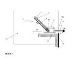
- FIG. 3 shows a further schematic plan view of the scratch tester (I) according to the invention on an examined glass sheet (14) with an applied angle (17).
- the structure of the scratch tester (I) according to the invention on a glass pane (14) corresponds to that in FIG. 2 described.
- the angle (17) is fixed with an angle bar (18) on the edge of the glass pane (14).
- the scratch tester (I) is subsequently moved in the direction of the disk inner surface in the test direction (15) by the disk edge (14a) along the angle (17) which is likewise preferably fastened to the same disk edge (14a).
- the length (A) of the spacer (13) without the end block (13b) limits and thus defines the traversable distance of the scratch tester (I).
- the angle (17) is preferably executed at right angles, but also angles between 45 ° and 135 ° are possible.
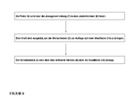
- FIG. 4 shows a flow chart of the inventive method for defined scratching a glass surface.
- the spring (5) via the adjustment device (7) within the Justierfernsters (6) is fixed.
- transmitted voltage is transmitted from the spring (5) a defined force on the holding block (9) and thus on the diamond (10).
- a force equivalent to the spring force set via the adjusting device (7) in the spring (5) is exerted on the hand of a test person until the slide rails (3) are brought to rest on a glass surface.
- the sliding block (2) of the scratch tester (I) is moved over the surface of the glass pane (14) over a preferably defined distance (A).
- the support of the spacer (13) with the end block (13b) marks the completion of the scratching operation on the surface of the glass sheet (14).
Abstract
Description
- Die Erfindung betrifft einen Kratztester für Glasscheiben, ein Verfahren zum Kratztesten von Glasscheiben und die Verwendung eines Kratztesters.
- Glas ist als in der Regel hochtransparenter und gleichzeitig harter Werkstoff sehr gefragt. Trotz seiner hohen Oberflächenhärte ist Glas ein oft spröder und häufig leicht zerbrechlicher Werkstoff. Die Beständigkeit, Festigkeit und Stabilität von Glasscheiben ist dabei in vielen Anwendungsbereichen von großer Bedeutung. Wichtige Bereiche sind Bauverglasungen, Fahrzeugverglasungen, Automobilverglasungen und Photovoltaikgläser. Die Beurteilung der physikalischen Parameter ist beim Werkstoff Glas auch aufgrund seiner amorphen Grundstruktur recht schwierig. Gleichzeitig sind Glasscheiben bei Fahrzeugen, insbesondere bei hohen Geschwindigkeiten und Fliehkräften, großen Belastungen ausgesetzt. Zur Einschätzung dieser Belastbarkeit sind daher einfache und gut reproduzierbare Testverfahren von großer Bedeutung. Insbesondere die ständig steigenden Kosten beim Glasbruch, beispielsweise durch Steinschlag, machen ein reproduzierbares Testverfahren der Glasscheiben notwendig. Der Scheibentest sollte sich dabei auf die Festigkeit der gesamten Windschutzscheibe beziehen. Es geht darum, ob ein (vermeintlich) kleiner und teils kaum sichtbarer Kratzer zu einem Windschutzscheiben-Bruch führen kann.
- Die Kratzfestigkeit eines Glases kann über verschiedene Methoden und Verfahren bestimmt werden. Hierzu können verschiedene Verfahren zur Bestimmung der Werkstoffhärte verwendet werden, beispielsweise die Härtebestimmung nach Mohs, Martens, Brinell und Vickers. Die genannten Verfahren bestimmen dabei in der Regel die auf die Glasoberfläche wirkenden Kräfte und/oder Eindringtiefen. Aufgrund der hohen Oberflächenhärte des Glases eigenen sich nur sehr harte Werkstoffe zum Kratzen von Glas. Geeignete Werkstoffe sind beispielsweise Siliziumcarbid und Diamant.
- Die Beurteilung der Messergebnisse ist beim Werkstoff Glas häufig mit größeren Schwierigkeiten verbunden. So können sich sichtbare oberflächliche Kratzer als Mikrorisse oder Haarrisse weit innerhalb des Glaskörpers ausbreiten. Diese kaum sichtbaren Beschädigungen des Glaskörpers können die Stabilität und Festigkeit des Glases ganz wesentlich beeinflussen. Variiert der Krafteintrag während einer Messung nur geringfügig, so kann sich die Ausdehnung der gebildeten Kratzer, besonders der Mikrorisse im Glaskörper deutlich unterscheiden. Die daraus resultierenden Messergebnisse und die Stabilität der Scheibe fallen so deutlich verschieden aus. Um reproduzierbare Messergebnisse zu erhalten, ist daher ein genau definierter Krafteintrag auf der Glasoberfläche notwendig.
-
US2002014778 A1 offenbart ein Verfahren zum Schutz von Windschutzscheiben eines Kraftfahrzeuges vor Steinschlag. Die Schutzwirkung wird durch eine resistente Barriere im Randbereich der Scheibe erzeugt. -
US 3,985,026 A offenbart eine Vorrichtung zum Testen von Oberflächenbeschichtungen auf Glasgegenständen. -
GB 2,449,174 A -
DE 10 2010 031 866 A1 offenbart eine silikonbeschichtete Glasoberfläche. Ein Kratztest dient zur Bestimmung der Oberflächeneigenschaften. Der Kratztest umfasst eine Wolframcarbidspitze mit einem Auflagegewicht von größer 500 g. - Die Aufgabe der Erfindung liegt darin, eine Vorrichtung bereitzustellen, welche eine Anritzung der Glasoberfläche und des oberflächennahen Glaskörpers mit einem konstanten und reproduzierbaren Krafteintrag, sowie eine sich über viele Tests unveränderte Geometrie der Kratzspitze gewährleistet.
- Die Aufgabe der vorliegenden Erfindung wird erfindungsgemäß durch den unabhängigen Anspruch 1 gelöst. Bevorzugte Ausführungen gehen aus den Unteransprüchen hervor.
- Ein erfindungsgemäßes Verfahren zum definierten Kratzen einer Glasoberfläche und die Verwendung des erfindungsgemäßen Kratztesters gehen aus weiteren unabhängigen Ansprüchen hervor.
- Der erfindungsgemäße Kratztester umfasst einen Kratzzylinder. Der Kratzzylinder ist als Hohlzylinder ausgebildet und umfasst eine innerhalb des Kratzzylinders beweglich gelagerte Feder. Die Feder ist innerhalb des Kratzzylinders mit einem Halteblock und einem am Halteblock befestigten Diamanten verbunden. Der Halteblock kann in Form mehrerer verbundener Bauteile ausgeführt sein. Der Halteblock fixiert den zum Ankratzen der Glasoberfläche befestigten Diamanten. Der Halteblock ist innerhalb des Kratzzylinders vertikal beweglich gelagert.
- Der Kratzzylinder umfasst entlang der Außenfläche weiterhin eine Aussparung oder Öffnung in Form eines Justierfensters. Die Feder ist innerhalb des Kratzzylinders im Bereich des Justierfensters mit einer Justiervorrichtung lose oder fest verbunden. Der Ausdruck "verbunden" umfasst im Sinne der Erfindung sowohl eine feste Verbindung mit der Feder als auch eine lose Verbindung, in der die Justiervorrichtung oder der Halteblock die Feder zusammendrückt. Die Justiervorrichtung ist bevorzugt als verschraubbarer Metallring ausgebildet.
- Der erfindungsgemäße Kratztester für Glasscheiben umfasst des Weiteren mindestens einen Schiebeblock mit einer Durchbohrung und zwei unterhalb des Schiebeblocks befindliche Gleitschienen. Der Schiebblock umfasst Metall-, Komposit- oder Kunststoffblöcke, bevorzugt aus Eisen, besonders bevorzugt aus Edelstahl. Der Schiebeblock erlaubt eine sichere Führung des erfindungsgemäßen Kratztesters und verhindert das Verrutschen. Der Kratzzylinder ist innerhalb der Durchbohrung des Schiebeblocks, beispielsweise mit einer Schraube oder Niete, fixiert. Der Kratzzylinder ist bevorzugt senkrecht zu den Gleitschienen in der Durchbohrung angeordnet. Der Kratzzylinder kann alternativ in einem Winkel von 70° bis 110° zu den Gleitschienen innerhalb der Durchbohrung angeordnet und fixiert sein.
- Der Kratzzylinder ist bevorzugt innerhalb der Durchbohrung über eine Feststellschraube fixiert. Die Feststellschraube ermöglicht einen schnellen und einfachen Austausch des Kratzzylinders, so dass der Kratztester mit verschiedenen Kratzzylindern verwendet werden kann. Der einfache und schnelle Wechsel des Kratzzylinders erlaubt zudem die schnelle Untersuchung verschiedener Glasscheibentypen hintereinander weg.
- Der Halteblock ist bevorzugt innerhalb eines Führungsrings beweglich gelagert. Der Führungsring ermöglicht den Einsatz von Halteblöcken, deren Durchmesser kleiner als der Durchmesser des Kratzzylinders ist.
- Der Führungsring ist bevorzugt über die Feststellschraube fixiert.
- Der Diamant umfasst bevorzugt Vickersdiamanten oder Diamanten mit einer Kegelform mit spitzen Winkel. Der Diamant weist bevorzugt im Bereich seiner Spitze die Form einer gleichseitigen Pyramide auf. Diese regelmäßige Geometrie erlaubt ein reproduzierbares Ankratzen der Glassoberfläche. Bei Abweichungen von der gleichseitigen Pyramidenform kann der Diamant mehrfach nachgeschliffen und somit häufig und kostengünstig wiederverwertet werden. Es eignen sich sowohl natürliche oder auch künstliche Industriediamanten.
- Der Schiebeblock weist bevorzugt einen Abstandshalter in Richtung der Gleitschienen auf. Der Abstandshalter ist bevorzugt so ausgebildet, dass wenn der Schiebeblock auf der Glasoberfläche anliegt, er über die Gleitschienen hinausragt. Der Abstandshalter erzeugt einen definierten Weg oder eine Strecke, über den der Kratztester ausgehend vom Kantenbereich über die Glasoberfläche geschoben werden kann. Eine weitere Messvorrichtung, beispielsweise ein Zentimetermass, ist nicht notwendig. Der Abstandshalter ist im Schnitt bevorzugt im Bereich eines Endblocks T-förmig ausgebildet. Der Endblock ist bevorzugt scheibenförmig ausgebildet, die Dicke des Endblocks beträgt bevorzugt 2 mm bis 40 mm. Der gesamte Abstandshalter weist bevorzugt eine Länge von 20 mm bis 150 mm auf.
- Der Abstand des Diamanten innerhalb des Kratzzylinders zur Glaskante wird über die Positionierung der Durchbohrung innerhalb des Schiebeblocks definiert. Ein Aufliegen des Diamanten auf der direkten Glaskante sollte vermieden werden, da die Glasspannungen im direkten Kantenbereich recht deutlich von der restlichen Scheibenfläche abweichen. Eine direkt an der Scheibenkante beginnende Messung würde daher das Messergebnis in seiner Gesamtheit verfälschen.
- Die Feder enthält bevorzugt ein Metall, besonders bevorzugt Aluminium, Titan, Eisen, Chrom, Vanadium, Kobalt, Nickel, Wolfram und/oder Legierungen davon, insbesondere bevorzugt Klavierdraht.
- Schiebeblock und/oder der Kratzzylinder enthalten bevorzugt ein Metall, besonders bevorzugt Aluminium, Titan, Eisen, Chrom, Vanadium, Kobalt, Nickel, Wolfram und/oder Legierungen davon.
- Der Schiebeblock und der Kratzzylinder enthalten in einer alternativen Ausgestaltung bevorzugt ein Polymer, bevorzugt Polyethylen, Polypropylen, Polystyrol, Polyurethane, Polymethylmetacrylate, Polyacrylate, Polyester, Polyamide, Polyethylenterephthalat und/oder Gemische oder Copolymere davon, besonders bevorzugt Polycarbontblends wie Polycarbobnat/Polyethylenterephthalat; Polycarbonat/Acrylnitril-Butadien-Styrol; Polycarbonat/Polybutylenterephthalat.
- Der Halteblock weist bevorzugt eine Einkerbung sowie der Kratzzylinder eine Arretierschraube auf. Die Einkerbung schließt die Spitze der Arretierschraube bevorzugt innerhalb des Kratzzylinders ein. Der Halteblock kann sich in diesem Fall nur in der Streck - und Dehnungsrichtung der Feder und entlang der Einkerbung bewegen. Eine Bewegung des Halteblocks entlang seiner Drehachse ist nur geringfügig möglich. Eine Verkantung des Halteblocks und damit des Diamanten auf der Glasoberfläche wird somit vermieden.
- Die Feder übt bevorzugt eine Kraft von 1 N bis 20 N aus und weist bevorzugt eine Federkonstante mit einem Wert von 2 N/m bis 100 N/m, bevorzugt 5 N/m bis 50 N/m auf. Die Federkraft richtet sich im Wesentlichen nach den geforderten Testbedingungen und der zu untersuchenden Glasoberfläche. Der Bereich von 1 N bis 20 N erlaubt ein reproduzierbares Ankratzen der Glasoberfläche. In Abhängigkeit von der Härte der Glasoberfläche können auch größere Kräfte notwendig sein.
- Der Diamant ist bevorzugt bei entspannter und gespannter Feder zwischen oder unterhalb der Gleitschienen positioniert. Bei gespannter Feder wird der Diamant weiter unterhalb der Gleitschienen positioniert, sodass der Diamant beim Aufsetzen des Kratztesters direkt auf der Glasoberfläche positioniert ist.
- Die Erfindung umfasst des Weiteren ein Verfahren zum definierten Kratzen einer Glasoberfläche mit einem wie oben beschriebenen erfindungsgemäßen Kratztester. In einem ersten Schritt wird die Feder über die Justagevorrichtung innerhalb des Justierfernsters fixiert. In Abhängigkeit von der Justierung wird von der Feder eine definierte Kraft auf den Halteblock und damit auf den Diamanten übertragen. In einem folgenden Schritt wird über die Hand einer Testperson eine der über die Justagevorrichtung in der Feder eingestellten Federkraft äquivalente Kraft ausgeübt, indem die Gleitschienen zur Auflage auf eine Glasfläche gebracht werden. In einem abschließenden Schritt wird der Schiebeblock über eine bevorzugt definierte Strecke über die Glasfläche bewegt.
- Der Schiebeblock wird bevorzugt bis zum Anschlag eines auf dem Schiebeblock befestigten Abstandshalters über die Glasfläche bewegt. Dazu wird der Schiebeblock auf den Rand der Glasscheibe mit den Gleitschienen zur Auflage gebracht. Im anschließenden Schritt wird der Schiebeblock in zum Abstandshalter entgegengesetzter Richtung bewegt, bis der Abstandshalter am Rand der Glasscheibe zur Auflage kommt. Der Abstandshalter erzeugt einen definierten Weg oder eine Strecke, über den der Kratztester ausgehend vom Kantenbereich über die Glasoberfläche geschoben werden kann.
- Die Erfindung umfasst des Weiteren die Verwendung des erfindungsgemäßen Kratztesters zum definierten Kratzen von Glasscheiben, bevorzugt Fahrzeugscheiben, besonders bevorzugt Windschutzscheiben, Seitenscheiben oder Heckscheiben. Der erfindungsgemäße Kratztester erlaubt eine Testung der Glasscheiben direkt am Produktionsstandort. Aufwendige, fest installierte Testapparaturen sind nicht notwendig.
- Im Folgenden wird die Erfindung anhand von einer Zeichnung näher erläutert. Die Zeichnung ist eine rein schematische Darstellung und nicht maßstabsgetreu. Sie schränkt die Erfindung in keiner Weise ein.
- Es zeigen:
-
Figur 1 einen Querschnitt des erfindungsgemäßen Kratztesters, -
Figur 2 eine schematische Draufsicht des erfindungsgemäßen Kratztesters, -
Figur 3 eine schematische Draufsicht einer bevorzugten Ausführungsform des Kratztesters und -
Figur 4 ein Fließschema des erfindungsgemäßen Verfahrens zum definierten Kratzen einer Glasoberfläche. -
Figur 1 zeigt einen Querschnitt des erfindungsgemäßen Kratztesters (I). Der Kratztester umfasst einen Schiebeblock (2) mit einer Durchbohrung (16). Zwei Gleitschienen (3) sind unterhalb des Schiebeblocks (2) angeordnet. Der Schiebblock (2) umfasst bevorzugt Metallblöcke, besonders bevorzugt aus Eisen, insbesondere bevorzugt aus Edelstahl. Der erfindungsgemäße Kratztester (I) umfasst des Weiteren einen Kratzzylinder (1). Der Kratzzylinder (1) ist als Hohlzylinder ausgebildet und umfasst eine innerhalb des Kratzzylinders (1) beweglich gelagerte Feder (5). Die Feder (5) ist innerhalb des Kratzzylinders (1) mit einem Halteblock (9) und einem am Halteblock (9) befestigten Diamanten (10) verbunden. Der Kratzzylinder (1) umfasst außerdem eine Aussparung in Form eines Justierfensters (6). Die Feder (5) ist innerhalb des Kratzzylinders (1) im Bereich des Justierfensters (6) mit einer Justiervorrichtung (7) lose oder fest verbunden. Die Justiervorrichtung (7) ist bevorzugt als verschraubbarer Metallring ausgebildet. Der Kratzzylinder (1) ist innerhalb der Durchbohrung (16) mit einer Feststellschraube (4) innerhalb einer Schraubenaussparung (12) im Schiebeblock (2) befestigt. Die Feststellschraube (4) kann bevorzugt an einer Schraubfläche (11) eines Einlegezylinders (8) und/oder einer Mutter (21) fixiert werden. Der Halteblock (9) ist innerhalb des Kratzzylinders (1) beweglich gelagert. Der Halteblock (9) weist eine Einkerbung (19) auf. Eine Arretierschraube (20) mit Mutter (21) begrenzt innerhalb der Einkerbung (19) die Bewegungsrichtung des Halteblocks (9). Der Halteblock kann sich begrenzt durch die Einkerbung (19) nur entlang der Mittelachse des Kratzzylinders (1) bewegen. Gleichzeitig ist der Halteblock (9) entlang seiner eigenen Drehachse fixiert gelagert. Eine Verkantung des Halteblocks (9) und damit des Diamanten (10) auf der Glasoberfläche wird somit vermieden. -
Figur 2 zeigt eine schematische Draufsicht des erfindungsgemäßen Kratztesters (I) auf einer zu testenden Glasscheibe (14). Der Schiebeblock (2) wird auf den nicht gezeigten Führungsschienen (3) entlang der durch den Abstandshalter (13) definierten Strecke (A) auf der Glasscheibe (14) in Prüfrichtung (15) bewegt. Innerhalb des Schiebeblocks (2) befindet sich der angedeutete Kratzzylinder (1). Die Einstellung der Federkraft der nicht gezeigten Feder (5) erfolgt innerhalb des Justierfensters (6) über die Justagevorrichtung (7). Durch Aufdrücken des Schiebeblocks (2) auf der Oberfläche der Glasscheibe (14) wird die über die Justagevorrichtung in der Feder (5) vorgegebene Kraft mittels des Diamanten (10) auf die Glasscheibe (14) übertragen. Über den am nicht gezeigten Montageblock (9) befestigten Diamanten (10) erfolgt das Einritzen der Oberfläche der Glasscheibe (14). -
Figur 3 zeigt eine weitere schematische Draufsicht des erfindungsgemäßen Kratztesters (I) auf einer zu testenden Glasscheibe (14) mit angelegtem Winkel (17). Der Aufbau des erfindungsgemäßen Kratztesters (I) auf einer Glasscheibe (14) entspricht dem inFigur 2 beschriebenen. Der Winkel (17) wird mit einer Winkelleiste (18) am Rand der Glasscheibe (14) fixiert. Der Kratztester (I) wird anschließend von der Scheibenkante (14a) entlang des ebenfalls bevorzugt an derselben Scheibenkante (14a) befestigten Winkels (17) in Richtung der Scheibeninnenfläche in Prüfrichtung (15) bewegt. Die Länge (A) des Abstandshalters (13) ohne den Endblock (13b) begrenzt und definiert damit die zurücklegbare Wegstrecke des Kratztesters (I). Der Winkel (17) ist bevorzugt rechtwinklig ausgeführt, es sind jedoch auch Winkel zwischen 45° und 135° möglich. -
Figur 4 zeigt ein Fließschema des erfindungsgemäßen Verfahrens zum definierten Kratzen einer Glasoberfläche. In einem ersten Schritt wird die Feder (5) über die Justagevorrichtung (7) innerhalb des Justierfernsters (6) fixiert. In Abhängigkeit von der Justierung und der auf die Feder (5) übertragenen Spannung wird von der Feder (5) eine definierte Kraft auf den Halteblock (9) und damit auf den Diamanten (10) übertragen. In einem folgenden Schritt wird über die Hand einer Testperson eine der über die Justagevorrichtung (7) in der Feder (5) eingestellten Federkraft äquivalente Kraft ausgeübt, bis die Gleitschienen (3) zur Auflage auf einer Glasfläche gebracht werden. In einem abschließenden Schritt wird der Schiebeblock (2) des Kratztesters (I) über eine bevorzugt definierte Strecke (A) über die Oberfläche der Glasscheibe (14) bewegt. Die Auflage des Abstandshalters (13) mit dem Endblock (13b) markiert den Abschluss des Kratzvorgangs auf der Oberfläche der Glasscheibe (14). -
- (A)
- Länge (des Abstandshalters) ohne Endblock (13b)
- (I)
- Kratztester
- (1)
- Kratzzylinder
- (2)
- Schiebeblock
- (3)
- Gleitschienen
- (4)
- Arretierschraube
- (5)
- Feder
- (6)
- Justierfenster
- (7)
- Justiervorrichtung
- (8)
- Einlegezylinder
- (9)
- Halteblock
- (10)
- Diamant
- (11)
- Schraubfläche
- (12)
- Schraubenaussparung
- (13)
- Abstandshalter
- (13b)
- Endblock
- (14)
- Glasscheibe
- (14a)
- Scheibenkante
- (15)
- Prüfrichtung
- (16)
- Durchbohrung
- (17)
- Winkel
- (18)
- Winkelleiste
- (19)
- Einkerbung
- (20)
- Arritrierschraube
- (21)
- Mutter
Claims (15)
- Kratztester für Glasscheiben mindestens umfassenda. einen Kratzzylinder (1) umfassend eine innerhalb des Kratzzylinders (1) gelagerte Feder (5), wobei die Feder (5) mit einem Halteblock (9) und einem am Halteblock (9) befestigten Diamanten (10) verbunden ist sowie eine innerhalb eines Justierfensters (6) entlang der Außenfläche des Kratzzylinders (1) mit der Feder (5) lose oder fest verbundene Justiervorrichtung (7),b. einen Schiebeblock (2) mit einer Durchbohrung (16) und zwei unterhalb des Schiebeblocks (2) befindliche Gleitschienen (3),c. wobei der Kratzzylinder (1) innerhalb der Durchbohrung (16) fixiert ist.
- Kratztester nach Anspruch 1, wobei der Kratzzylinder (1) innerhalb der Durchbohrung (16) über eine Feststellschraube (4) fixiert ist.
- Kratztester nach Anspruch 1 oder 2, wobei der Halteblock (9) innerhalb eines Führungsrings (8) beweglich gelagert ist.
- Kratztester nach Anspruch 3, wobei der Führungsring (8) über die Feststellschraube (4) fixiert ist.
- Kratztester nach einem der Ansprüche 1 bis 4, wobei der Diamant (10) Vickersdiamanten umfasst.
- Kratztester nach einem der Ansprüche 1 bis 5, wobei der Diamant (10) die Form einer gleichseitigen Pyramide aufweist.
- Kratztester nach einem der Ansprüche 1 bis 6, wobei der Schiebeblock (2) einen Abstandshalter (13) mit einen Endblock (13b) in Richtung der Gleitschienen (3) aufweist.
- Kratztester nach Anspruch 7, wobei der Endblock (13b) im Schnitt T-förmig ausgebildet ist.
- Kratztester nach einem der Ansprüche 1 bis 8, wobei der Schiebeblock (2) ein Metall, bevorzugt Aluminium, Titan, Eisen, Chrom, Vanadium, Kobalt, Nickel, Wolfram und/oder Legierungen davon enthält.
- Kratztester nach einem der Ansprüche 1 bis 9, wobei der Halteblock (9) eine Einkerbung (19) sowie der Kratzzylinder (1) eine Arretierschraube (4) aufweisen und die Einkerbung (19) die Arretierschraube (4) innerhalb des Kratzzylinders (1) umschließt.
- Kratztester nach einem der Ansprüche 1 bis 10, wobei die Feder (5) eine Kraft von 1 N bis 20 N ausübt.
- Kratztester nach einem der Ansprüche 1 bis 11, wobei der Diamant (10) bei entspannter Feder (5) zwischen oder unterhalb der Gleitschienen (3) positioniert ist.
- Verfahren zum definierten Kratzen einer Glasoberfläche mit einem Kratztester nach einem der Ansprüche 1 bis 11, wobeia. die Feder (5) über die Justagevorrichtung (7) in dem Justierfernster (6) fixiert wird,b. eine Kraft von oben auf den Schiebeblock (2) ausgeübt wird, um die Gleitschienen (3) zur Auflage auf einer Glasfläche (14) zu bringen undc. der Schiebeblock (2) über die Glasfläche (14) bewegt wird.
- Verfahren nach Anspruch 13, wobei der Schiebeblock (2) bis zum Anschlag eines auf dem Schiebeblock (2) befestigten Abstandshalters (13) über die Glasfläche (14) bewegt wird.
- Verwendung des Kratztesters nach einem der Ansprüche 1 bis 12 zum definierten Kratzen von Glasscheiben, bevorzugt Fahrzeugscheiben, besonders bevorzugt Windschutzscheiben.
Priority Applications (1)
| Application Number | Priority Date | Filing Date | Title |
|---|---|---|---|
| EP12173369.5A EP2679979B1 (de) | 2012-06-25 | 2012-06-25 | Kratztester für Glasscheiben |
Applications Claiming Priority (1)
| Application Number | Priority Date | Filing Date | Title |
|---|---|---|---|
| EP12173369.5A EP2679979B1 (de) | 2012-06-25 | 2012-06-25 | Kratztester für Glasscheiben |
Publications (2)
| Publication Number | Publication Date |
|---|---|
| EP2679979A1 true EP2679979A1 (de) | 2014-01-01 |
| EP2679979B1 EP2679979B1 (de) | 2019-11-06 |
Family
ID=46458192
Family Applications (1)
| Application Number | Title | Priority Date | Filing Date |
|---|---|---|---|
| EP12173369.5A Active EP2679979B1 (de) | 2012-06-25 | 2012-06-25 | Kratztester für Glasscheiben |
Country Status (1)
| Country | Link |
|---|---|
| EP (1) | EP2679979B1 (de) |
Cited By (2)
| Publication number | Priority date | Publication date | Assignee | Title |
|---|---|---|---|---|
| DE102014016482A1 (de) | 2014-11-07 | 2016-05-12 | Wolfgang Weinhold | Test- und/oder Prüfvorrichtung |
| CN113137944A (zh) * | 2021-04-28 | 2021-07-20 | 卢玉蓉 | 一种医用光学玻璃制备检测装置及检测方法 |
Citations (11)
| Publication number | Priority date | Publication date | Assignee | Title |
|---|---|---|---|---|
| DE445901C (de) * | 1925-10-25 | 1927-06-18 | Mueller Friedrich | Schnitthaertepruefer |
| US3985026A (en) | 1975-04-04 | 1976-10-12 | Owens-Illinois, Inc. | Surface coating test apparatus |
| JP2001091444A (ja) * | 1999-09-24 | 2001-04-06 | Hitachi Ltd | 引掻き試験機 |
| US20020014778A1 (en) | 1996-05-07 | 2002-02-07 | Richard Campfield | Method and means for protecting a windshield from cracks |
| KR20040047470A (ko) * | 2002-11-30 | 2004-06-05 | 한국표준과학연구원 | 3축 힘센서를 이용한 스크레치 측정장치 |
| FR2895800A1 (fr) * | 2006-01-02 | 2007-07-06 | Peugeot Citroen Automobiles Sa | Procede de determination de la resistance a la rayure d'un vitrage. |
| GB2449174A (en) | 2007-05-09 | 2008-11-12 | Pilkington Group Ltd | Printed automotive glazing |
| JP2008292293A (ja) * | 2007-05-24 | 2008-12-04 | Kozosoken Corp | 硬度測定用引っかき傷生成装置 |
| US20100206041A1 (en) * | 2009-02-19 | 2010-08-19 | Sungkyunkwan University Foundation Corporate Collaboration | Scratch testing apparatus for performing scratching test while gradually increasing or decreasing load |
| DE102010034118A1 (de) * | 2010-06-18 | 2011-12-22 | Printec Gmbh | Vorrichtung zur Prüfung der Oberflächenqualität von flächigen Prüflingen |
| DE102010031866A1 (de) | 2010-07-21 | 2012-01-26 | Schott Ag | Silikonbeschichtung als Versiegelungsschicht für eine Dekorbeschichtung |
-
2012
- 2012-06-25 EP EP12173369.5A patent/EP2679979B1/de active Active
Patent Citations (11)
| Publication number | Priority date | Publication date | Assignee | Title |
|---|---|---|---|---|
| DE445901C (de) * | 1925-10-25 | 1927-06-18 | Mueller Friedrich | Schnitthaertepruefer |
| US3985026A (en) | 1975-04-04 | 1976-10-12 | Owens-Illinois, Inc. | Surface coating test apparatus |
| US20020014778A1 (en) | 1996-05-07 | 2002-02-07 | Richard Campfield | Method and means for protecting a windshield from cracks |
| JP2001091444A (ja) * | 1999-09-24 | 2001-04-06 | Hitachi Ltd | 引掻き試験機 |
| KR20040047470A (ko) * | 2002-11-30 | 2004-06-05 | 한국표준과학연구원 | 3축 힘센서를 이용한 스크레치 측정장치 |
| FR2895800A1 (fr) * | 2006-01-02 | 2007-07-06 | Peugeot Citroen Automobiles Sa | Procede de determination de la resistance a la rayure d'un vitrage. |
| GB2449174A (en) | 2007-05-09 | 2008-11-12 | Pilkington Group Ltd | Printed automotive glazing |
| JP2008292293A (ja) * | 2007-05-24 | 2008-12-04 | Kozosoken Corp | 硬度測定用引っかき傷生成装置 |
| US20100206041A1 (en) * | 2009-02-19 | 2010-08-19 | Sungkyunkwan University Foundation Corporate Collaboration | Scratch testing apparatus for performing scratching test while gradually increasing or decreasing load |
| DE102010034118A1 (de) * | 2010-06-18 | 2011-12-22 | Printec Gmbh | Vorrichtung zur Prüfung der Oberflächenqualität von flächigen Prüflingen |
| DE102010031866A1 (de) | 2010-07-21 | 2012-01-26 | Schott Ag | Silikonbeschichtung als Versiegelungsschicht für eine Dekorbeschichtung |
Cited By (4)
| Publication number | Priority date | Publication date | Assignee | Title |
|---|---|---|---|---|
| DE102014016482A1 (de) | 2014-11-07 | 2016-05-12 | Wolfgang Weinhold | Test- und/oder Prüfvorrichtung |
| WO2016070864A1 (de) | 2014-11-07 | 2016-05-12 | Wolfgang Weinhold | Test- und/oder prüfvorrichtung |
| EP4043859A1 (de) | 2014-11-07 | 2022-08-17 | Wolfgang P. Weinhold | Test- und/oder prüfvorrichtung |
| CN113137944A (zh) * | 2021-04-28 | 2021-07-20 | 卢玉蓉 | 一种医用光学玻璃制备检测装置及检测方法 |
Also Published As
| Publication number | Publication date |
|---|---|
| EP2679979B1 (de) | 2019-11-06 |
Similar Documents
| Publication | Publication Date | Title |
|---|---|---|
| AT518154B1 (de) | Verfahren und Vorrichtung zum Trennen eines Werkstückes | |
| WO2008125281A1 (de) | Verfahren und zweipunktbiegemaschine zur messung einer materialeigenschaft | |
| EP2679979B1 (de) | Kratztester für Glasscheiben | |
| DE102013110098A1 (de) | Chemisch vorgespanntes Glaselement und Verfahren zu dessen Herstellung | |
| DE102015006274A1 (de) | Verfahren zur Ermittlung von wenigstens einem Kennwert zur Umformbarkeit eines Materials und Vorrichtung zur Durchführung eines solchen Verfahrens | |
| DE202015006725U1 (de) | Vorrichtung zum Überprüfen eines Martindale-Probenhalters mit eingesetzter Probe sowie Anordnung umfassend die Vorrichtung und den Probenhalter | |
| EP1991865B1 (de) | Vorrichtung zur prüfung der qualität einer metallischen beschichtung | |
| EP2773933B1 (de) | Verfahren zur ermittlung eines bearbeitungsergebnisses bei einer oberflächenbearbeitung von bauteilen | |
| EP2638353B1 (de) | Vorrichtung und verfahren zum definierten beschleunigen eines projektils | |
| EP3203208B1 (de) | Verfahren zur pruefung einer keramischen komponente | |
| DE102017220946A1 (de) | Graviervorrichtung und Verfahren zur Erzeugung und Messung von Spannungsrisskorrosion an einem flächigen beschichteten Prüfkörper | |
| DE102010034118A1 (de) | Vorrichtung zur Prüfung der Oberflächenqualität von flächigen Prüflingen | |
| DE10013688B4 (de) | Verwendung eines Verfahren zur Herstellung einer, aus anorganischem Glas bestehenden Schnittstreckerplatte | |
| DE3926676C2 (de) | Verfahren zur Messung der Materialbeschaffenheit eines Körpers hinsichtlich Abrieb, Verschleißfestigkeit oder Härte sowie Anwendung des Verfahrens | |
| DE2332329C2 (de) | Meßschnittvorrichlung zur Messung der Dicke einer auf eine Unterlage festhaftend aufgebrachten Schicht | |
| DE102015005146A1 (de) | Prüfverfahren und Prüfeinrichtung zur zerstörungsfreien Ermittlung festigkeits- und/oder umformtechnisch relevanter Materialkennwerte eines zu prüfenden Blechbauteiles auf Basis des ebenen Torsionsversuchs | |
| EP1380832B1 (de) | Verfahren zur Bestimmung der Hafteigenschaften von Materialien | |
| DE102016107552B4 (de) | Druckprüfungsvorrichtung für eine Werkstoff-Probe und Druckprüfungsverfahren | |
| DE3741992C2 (de) | Verwendung einer Prüfeinrichtung zur Ermittlung des Widerstandes gegen schneidende Verschleißbeanspruchung | |
| DE102009014680B4 (de) | Gitterschnitt-Prüfgerät | |
| DE102016008694A1 (de) | Verfahren und Vorrichtung zur Ermittlung einer Härte in einer bestimmten Tiefe eines zumindest bereichsweise gehärteten Bauteils | |
| WO2018114430A1 (de) | Verfahren zur prüfung der hafteigenschaften harter schichten | |
| EP2784476B1 (de) | Vorrichtung und Verfahren zur Lagerung von Probenkörpern | |
| DE102005017450B4 (de) | Verfahren zur Bestimmung der Temperatur von Bauteilen eines Kraftfahrzeugs | |
| DE102008021072B4 (de) | Verfahren zum Messen von Kanten- oder Randspannungen in Glasscheiben |
Legal Events
| Date | Code | Title | Description |
|---|---|---|---|
| PUAI | Public reference made under article 153(3) epc to a published international application that has entered the european phase |
Free format text: ORIGINAL CODE: 0009012 |
|
| AK | Designated contracting states |
Kind code of ref document: A1 Designated state(s): AL AT BE BG CH CY CZ DE DK EE ES FI FR GB GR HR HU IE IS IT LI LT LU LV MC MK MT NL NO PL PT RO RS SE SI SK SM TR |
|
| AX | Request for extension of the european patent |
Extension state: BA ME |
|
| 17P | Request for examination filed |
Effective date: 20140630 |
|
| RBV | Designated contracting states (corrected) |
Designated state(s): AL AT BE BG CH CY CZ DE DK EE ES FI FR GB GR HR HU IE IS IT LI LT LU LV MC MK MT NL NO PL PT RO RS SE SI SK SM TR |
|
| STAA | Information on the status of an ep patent application or granted ep patent |
Free format text: STATUS: EXAMINATION IS IN PROGRESS |
|
| 17Q | First examination report despatched |
Effective date: 20190208 |
|
| GRAP | Despatch of communication of intention to grant a patent |
Free format text: ORIGINAL CODE: EPIDOSNIGR1 |
|
| STAA | Information on the status of an ep patent application or granted ep patent |
Free format text: STATUS: GRANT OF PATENT IS INTENDED |
|
| INTG | Intention to grant announced |
Effective date: 20190827 |
|
| GRAS | Grant fee paid |
Free format text: ORIGINAL CODE: EPIDOSNIGR3 |
|
| GRAA | (expected) grant |
Free format text: ORIGINAL CODE: 0009210 |
|
| STAA | Information on the status of an ep patent application or granted ep patent |
Free format text: STATUS: THE PATENT HAS BEEN GRANTED |
|
| AK | Designated contracting states |
Kind code of ref document: B1 Designated state(s): AL AT BE BG CH CY CZ DE DK EE ES FI FR GB GR HR HU IE IS IT LI LT LU LV MC MK MT NL NO PL PT RO RS SE SI SK SM TR |
|
| REG | Reference to a national code |
Ref country code: GB Ref legal event code: FG4D Free format text: NOT ENGLISH |
|
| REG | Reference to a national code |
Ref country code: CH Ref legal event code: EP Ref country code: AT Ref legal event code: REF Ref document number: 1199410 Country of ref document: AT Kind code of ref document: T Effective date: 20191115 |
|
| REG | Reference to a national code |
Ref country code: IE Ref legal event code: FG4D Free format text: LANGUAGE OF EP DOCUMENT: GERMAN |
|
| REG | Reference to a national code |
Ref country code: DE Ref legal event code: R096 Ref document number: 502012015478 Country of ref document: DE |
|
| REG | Reference to a national code |
Ref country code: NL Ref legal event code: MP Effective date: 20191106 |
|
| REG | Reference to a national code |
Ref country code: LT Ref legal event code: MG4D |
|
| PG25 | Lapsed in a contracting state [announced via postgrant information from national office to epo] |
Ref country code: PT Free format text: LAPSE BECAUSE OF FAILURE TO SUBMIT A TRANSLATION OF THE DESCRIPTION OR TO PAY THE FEE WITHIN THE PRESCRIBED TIME-LIMIT Effective date: 20200306 Ref country code: ES Free format text: LAPSE BECAUSE OF FAILURE TO SUBMIT A TRANSLATION OF THE DESCRIPTION OR TO PAY THE FEE WITHIN THE PRESCRIBED TIME-LIMIT Effective date: 20191106 Ref country code: NL Free format text: LAPSE BECAUSE OF FAILURE TO SUBMIT A TRANSLATION OF THE DESCRIPTION OR TO PAY THE FEE WITHIN THE PRESCRIBED TIME-LIMIT Effective date: 20191106 Ref country code: GR Free format text: LAPSE BECAUSE OF FAILURE TO SUBMIT A TRANSLATION OF THE DESCRIPTION OR TO PAY THE FEE WITHIN THE PRESCRIBED TIME-LIMIT Effective date: 20200207 Ref country code: LT Free format text: LAPSE BECAUSE OF FAILURE TO SUBMIT A TRANSLATION OF THE DESCRIPTION OR TO PAY THE FEE WITHIN THE PRESCRIBED TIME-LIMIT Effective date: 20191106 Ref country code: BG Free format text: LAPSE BECAUSE OF FAILURE TO SUBMIT A TRANSLATION OF THE DESCRIPTION OR TO PAY THE FEE WITHIN THE PRESCRIBED TIME-LIMIT Effective date: 20200206 Ref country code: NO Free format text: LAPSE BECAUSE OF FAILURE TO SUBMIT A TRANSLATION OF THE DESCRIPTION OR TO PAY THE FEE WITHIN THE PRESCRIBED TIME-LIMIT Effective date: 20200206 Ref country code: PL Free format text: LAPSE BECAUSE OF FAILURE TO SUBMIT A TRANSLATION OF THE DESCRIPTION OR TO PAY THE FEE WITHIN THE PRESCRIBED TIME-LIMIT Effective date: 20191106 Ref country code: LV Free format text: LAPSE BECAUSE OF FAILURE TO SUBMIT A TRANSLATION OF THE DESCRIPTION OR TO PAY THE FEE WITHIN THE PRESCRIBED TIME-LIMIT Effective date: 20191106 Ref country code: FI Free format text: LAPSE BECAUSE OF FAILURE TO SUBMIT A TRANSLATION OF THE DESCRIPTION OR TO PAY THE FEE WITHIN THE PRESCRIBED TIME-LIMIT Effective date: 20191106 Ref country code: SE Free format text: LAPSE BECAUSE OF FAILURE TO SUBMIT A TRANSLATION OF THE DESCRIPTION OR TO PAY THE FEE WITHIN THE PRESCRIBED TIME-LIMIT Effective date: 20191106 |
|
| PG25 | Lapsed in a contracting state [announced via postgrant information from national office to epo] |
Ref country code: RS Free format text: LAPSE BECAUSE OF FAILURE TO SUBMIT A TRANSLATION OF THE DESCRIPTION OR TO PAY THE FEE WITHIN THE PRESCRIBED TIME-LIMIT Effective date: 20191106 Ref country code: IS Free format text: LAPSE BECAUSE OF FAILURE TO SUBMIT A TRANSLATION OF THE DESCRIPTION OR TO PAY THE FEE WITHIN THE PRESCRIBED TIME-LIMIT Effective date: 20200306 Ref country code: HR Free format text: LAPSE BECAUSE OF FAILURE TO SUBMIT A TRANSLATION OF THE DESCRIPTION OR TO PAY THE FEE WITHIN THE PRESCRIBED TIME-LIMIT Effective date: 20191106 |
|
| RAP2 | Party data changed (patent owner data changed or rights of a patent transferred) |
Owner name: SAINT-GOBAIN GLASS FRANCE |
|
| PG25 | Lapsed in a contracting state [announced via postgrant information from national office to epo] |
Ref country code: AL Free format text: LAPSE BECAUSE OF FAILURE TO SUBMIT A TRANSLATION OF THE DESCRIPTION OR TO PAY THE FEE WITHIN THE PRESCRIBED TIME-LIMIT Effective date: 20191106 |
|
| PG25 | Lapsed in a contracting state [announced via postgrant information from national office to epo] |
Ref country code: DK Free format text: LAPSE BECAUSE OF FAILURE TO SUBMIT A TRANSLATION OF THE DESCRIPTION OR TO PAY THE FEE WITHIN THE PRESCRIBED TIME-LIMIT Effective date: 20191106 Ref country code: CZ Free format text: LAPSE BECAUSE OF FAILURE TO SUBMIT A TRANSLATION OF THE DESCRIPTION OR TO PAY THE FEE WITHIN THE PRESCRIBED TIME-LIMIT Effective date: 20191106 Ref country code: RO Free format text: LAPSE BECAUSE OF FAILURE TO SUBMIT A TRANSLATION OF THE DESCRIPTION OR TO PAY THE FEE WITHIN THE PRESCRIBED TIME-LIMIT Effective date: 20191106 Ref country code: EE Free format text: LAPSE BECAUSE OF FAILURE TO SUBMIT A TRANSLATION OF THE DESCRIPTION OR TO PAY THE FEE WITHIN THE PRESCRIBED TIME-LIMIT Effective date: 20191106 |
|
| REG | Reference to a national code |
Ref country code: DE Ref legal event code: R097 Ref document number: 502012015478 Country of ref document: DE |
|
| PG25 | Lapsed in a contracting state [announced via postgrant information from national office to epo] |
Ref country code: SM Free format text: LAPSE BECAUSE OF FAILURE TO SUBMIT A TRANSLATION OF THE DESCRIPTION OR TO PAY THE FEE WITHIN THE PRESCRIBED TIME-LIMIT Effective date: 20191106 Ref country code: SK Free format text: LAPSE BECAUSE OF FAILURE TO SUBMIT A TRANSLATION OF THE DESCRIPTION OR TO PAY THE FEE WITHIN THE PRESCRIBED TIME-LIMIT Effective date: 20191106 |
|
| PLBE | No opposition filed within time limit |
Free format text: ORIGINAL CODE: 0009261 |
|
| STAA | Information on the status of an ep patent application or granted ep patent |
Free format text: STATUS: NO OPPOSITION FILED WITHIN TIME LIMIT |
|
| 26N | No opposition filed |
Effective date: 20200807 |
|
| PG25 | Lapsed in a contracting state [announced via postgrant information from national office to epo] |
Ref country code: SI Free format text: LAPSE BECAUSE OF FAILURE TO SUBMIT A TRANSLATION OF THE DESCRIPTION OR TO PAY THE FEE WITHIN THE PRESCRIBED TIME-LIMIT Effective date: 20191106 |
|
| PG25 | Lapsed in a contracting state [announced via postgrant information from national office to epo] |
Ref country code: MC Free format text: LAPSE BECAUSE OF FAILURE TO SUBMIT A TRANSLATION OF THE DESCRIPTION OR TO PAY THE FEE WITHIN THE PRESCRIBED TIME-LIMIT Effective date: 20191106 Ref country code: IT Free format text: LAPSE BECAUSE OF FAILURE TO SUBMIT A TRANSLATION OF THE DESCRIPTION OR TO PAY THE FEE WITHIN THE PRESCRIBED TIME-LIMIT Effective date: 20191106 |
|
| REG | Reference to a national code |
Ref country code: CH Ref legal event code: PL |
|
| PG25 | Lapsed in a contracting state [announced via postgrant information from national office to epo] |
Ref country code: LU Free format text: LAPSE BECAUSE OF NON-PAYMENT OF DUE FEES Effective date: 20200625 |
|
| REG | Reference to a national code |
Ref country code: BE Ref legal event code: MM Effective date: 20200630 |
|
| PG25 | Lapsed in a contracting state [announced via postgrant information from national office to epo] |
Ref country code: LI Free format text: LAPSE BECAUSE OF NON-PAYMENT OF DUE FEES Effective date: 20200630 Ref country code: IE Free format text: LAPSE BECAUSE OF NON-PAYMENT OF DUE FEES Effective date: 20200625 Ref country code: CH Free format text: LAPSE BECAUSE OF NON-PAYMENT OF DUE FEES Effective date: 20200630 |
|
| PG25 | Lapsed in a contracting state [announced via postgrant information from national office to epo] |
Ref country code: BE Free format text: LAPSE BECAUSE OF NON-PAYMENT OF DUE FEES Effective date: 20200630 |
|
| REG | Reference to a national code |
Ref country code: AT Ref legal event code: MM01 Ref document number: 1199410 Country of ref document: AT Kind code of ref document: T Effective date: 20200625 |
|
| PG25 | Lapsed in a contracting state [announced via postgrant information from national office to epo] |
Ref country code: AT Free format text: LAPSE BECAUSE OF NON-PAYMENT OF DUE FEES Effective date: 20200625 |
|
| PG25 | Lapsed in a contracting state [announced via postgrant information from national office to epo] |
Ref country code: TR Free format text: LAPSE BECAUSE OF FAILURE TO SUBMIT A TRANSLATION OF THE DESCRIPTION OR TO PAY THE FEE WITHIN THE PRESCRIBED TIME-LIMIT Effective date: 20191106 Ref country code: MT Free format text: LAPSE BECAUSE OF FAILURE TO SUBMIT A TRANSLATION OF THE DESCRIPTION OR TO PAY THE FEE WITHIN THE PRESCRIBED TIME-LIMIT Effective date: 20191106 Ref country code: CY Free format text: LAPSE BECAUSE OF FAILURE TO SUBMIT A TRANSLATION OF THE DESCRIPTION OR TO PAY THE FEE WITHIN THE PRESCRIBED TIME-LIMIT Effective date: 20191106 |
|
| PG25 | Lapsed in a contracting state [announced via postgrant information from national office to epo] |
Ref country code: MK Free format text: LAPSE BECAUSE OF FAILURE TO SUBMIT A TRANSLATION OF THE DESCRIPTION OR TO PAY THE FEE WITHIN THE PRESCRIBED TIME-LIMIT Effective date: 20191106 |
|
| PGFP | Annual fee paid to national office [announced via postgrant information from national office to epo] |
Ref country code: GB Payment date: 20220506 Year of fee payment: 11 Ref country code: FR Payment date: 20220510 Year of fee payment: 11 Ref country code: DE Payment date: 20220505 Year of fee payment: 11 |
|
| REG | Reference to a national code |
Ref country code: DE Ref legal event code: R119 Ref document number: 502012015478 Country of ref document: DE |
|
| GBPC | Gb: european patent ceased through non-payment of renewal fee |
Effective date: 20230625 |