EP2679977B1 - Method and device for measuring inter-core crosstalk of a multi-core optical fiber - Google Patents
Method and device for measuring inter-core crosstalk of a multi-core optical fiber Download PDFInfo
- Publication number
- EP2679977B1 EP2679977B1 EP12749190.0A EP12749190A EP2679977B1 EP 2679977 B1 EP2679977 B1 EP 2679977B1 EP 12749190 A EP12749190 A EP 12749190A EP 2679977 B1 EP2679977 B1 EP 2679977B1
- Authority
- EP
- European Patent Office
- Prior art keywords
- light
- optical fiber
- core
- receiving
- cladding
- Prior art date
- Legal status (The legal status is an assumption and is not a legal conclusion. Google has not performed a legal analysis and makes no representation as to the accuracy of the status listed.)
- Active
Links
- 239000013307 optical fiber Substances 0.000 title claims description 223
- 238000000034 method Methods 0.000 title claims description 18
- 238000005253 cladding Methods 0.000 claims description 68
- 230000000994 depressogenic effect Effects 0.000 claims description 30
- 239000011521 glass Substances 0.000 claims description 27
- 239000011248 coating agent Substances 0.000 claims description 21
- 238000000576 coating method Methods 0.000 claims description 21
- 239000000853 adhesive Substances 0.000 claims description 19
- 230000001070 adhesive effect Effects 0.000 claims description 19
- 239000007787 solid Substances 0.000 claims description 9
- 239000000463 material Substances 0.000 claims description 8
- 230000000717 retained effect Effects 0.000 claims description 3
- 239000010410 layer Substances 0.000 description 51
- 238000010168 coupling process Methods 0.000 description 41
- 238000005859 coupling reaction Methods 0.000 description 41
- 230000008878 coupling Effects 0.000 description 37
- 238000005259 measurement Methods 0.000 description 21
- 239000000835 fiber Substances 0.000 description 11
- 230000003287 optical effect Effects 0.000 description 11
- 238000010586 diagram Methods 0.000 description 9
- MCMNRKCIXSYSNV-UHFFFAOYSA-N Zirconium dioxide Chemical compound O=[Zr]=O MCMNRKCIXSYSNV-UHFFFAOYSA-N 0.000 description 8
- 238000006073 displacement reaction Methods 0.000 description 7
- 239000012792 core layer Substances 0.000 description 6
- 230000000694 effects Effects 0.000 description 4
- 239000002184 metal Substances 0.000 description 4
- 230000005684 electric field Effects 0.000 description 3
- 230000004888 barrier function Effects 0.000 description 2
- 230000005540 biological transmission Effects 0.000 description 2
- 230000007423 decrease Effects 0.000 description 2
- 230000001419 dependent effect Effects 0.000 description 1
- 230000004927 fusion Effects 0.000 description 1
- 230000002401 inhibitory effect Effects 0.000 description 1
- 238000011835 investigation Methods 0.000 description 1
- 230000001902 propagating effect Effects 0.000 description 1
Images


Classifications
-
- G—PHYSICS
- G02—OPTICS
- G02B—OPTICAL ELEMENTS, SYSTEMS OR APPARATUS
- G02B6/00—Light guides; Structural details of arrangements comprising light guides and other optical elements, e.g. couplings
- G02B6/24—Coupling light guides
- G02B6/26—Optical coupling means
- G02B6/262—Optical details of coupling light into, or out of, or between fibre ends, e.g. special fibre end shapes or associated optical elements
-
- G—PHYSICS
- G01—MEASURING; TESTING
- G01M—TESTING STATIC OR DYNAMIC BALANCE OF MACHINES OR STRUCTURES; TESTING OF STRUCTURES OR APPARATUS, NOT OTHERWISE PROVIDED FOR
- G01M11/00—Testing of optical apparatus; Testing structures by optical methods not otherwise provided for
- G01M11/08—Testing mechanical properties
- G01M11/088—Testing mechanical properties of optical fibres; Mechanical features associated with the optical testing of optical fibres
-
- G—PHYSICS
- G01—MEASURING; TESTING
- G01M—TESTING STATIC OR DYNAMIC BALANCE OF MACHINES OR STRUCTURES; TESTING OF STRUCTURES OR APPARATUS, NOT OTHERWISE PROVIDED FOR
- G01M11/00—Testing of optical apparatus; Testing structures by optical methods not otherwise provided for
- G01M11/30—Testing of optical devices, constituted by fibre optics or optical waveguides
- G01M11/33—Testing of optical devices, constituted by fibre optics or optical waveguides with a light emitter being disposed at one fibre or waveguide end-face, and a light receiver at the other end-face
-
- G—PHYSICS
- G02—OPTICS
- G02B—OPTICAL ELEMENTS, SYSTEMS OR APPARATUS
- G02B6/00—Light guides; Structural details of arrangements comprising light guides and other optical elements, e.g. couplings
- G02B6/02—Optical fibres with cladding with or without a coating
- G02B6/02042—Multicore optical fibres
-
- G—PHYSICS
- G02—OPTICS
- G02B—OPTICAL ELEMENTS, SYSTEMS OR APPARATUS
- G02B6/00—Light guides; Structural details of arrangements comprising light guides and other optical elements, e.g. couplings
- G02B6/02—Optical fibres with cladding with or without a coating
- G02B6/036—Optical fibres with cladding with or without a coating core or cladding comprising multiple layers
- G02B6/03616—Optical fibres characterised both by the number of different refractive index layers around the central core segment, i.e. around the innermost high index core layer, and their relative refractive index difference
- G02B6/03622—Optical fibres characterised both by the number of different refractive index layers around the central core segment, i.e. around the innermost high index core layer, and their relative refractive index difference having 2 layers only
- G02B6/03627—Optical fibres characterised both by the number of different refractive index layers around the central core segment, i.e. around the innermost high index core layer, and their relative refractive index difference having 2 layers only arranged - +
-
- G—PHYSICS
- G02—OPTICS
- G02B—OPTICAL ELEMENTS, SYSTEMS OR APPARATUS
- G02B6/00—Light guides; Structural details of arrangements comprising light guides and other optical elements, e.g. couplings
- G02B6/24—Coupling light guides
- G02B6/36—Mechanical coupling means
- G02B6/40—Mechanical coupling means having fibre bundle mating means
- G02B6/403—Mechanical coupling means having fibre bundle mating means of the ferrule type, connecting a pair of ferrules
-
- G—PHYSICS
- G02—OPTICS
- G02B—OPTICAL ELEMENTS, SYSTEMS OR APPARATUS
- G02B6/00—Light guides; Structural details of arrangements comprising light guides and other optical elements, e.g. couplings
- G02B6/02—Optical fibres with cladding with or without a coating
- G02B6/036—Optical fibres with cladding with or without a coating core or cladding comprising multiple layers
- G02B6/03616—Optical fibres characterised both by the number of different refractive index layers around the central core segment, i.e. around the innermost high index core layer, and their relative refractive index difference
- G02B6/03638—Optical fibres characterised both by the number of different refractive index layers around the central core segment, i.e. around the innermost high index core layer, and their relative refractive index difference having 3 layers only
- G02B6/0365—Optical fibres characterised both by the number of different refractive index layers around the central core segment, i.e. around the innermost high index core layer, and their relative refractive index difference having 3 layers only arranged - - +
-
- G—PHYSICS
- G02—OPTICS
- G02B—OPTICAL ELEMENTS, SYSTEMS OR APPARATUS
- G02B6/00—Light guides; Structural details of arrangements comprising light guides and other optical elements, e.g. couplings
- G02B6/02—Optical fibres with cladding with or without a coating
- G02B6/036—Optical fibres with cladding with or without a coating core or cladding comprising multiple layers
- G02B6/03616—Optical fibres characterised both by the number of different refractive index layers around the central core segment, i.e. around the innermost high index core layer, and their relative refractive index difference
- G02B6/03661—Optical fibres characterised both by the number of different refractive index layers around the central core segment, i.e. around the innermost high index core layer, and their relative refractive index difference having 4 layers only
- G02B6/03677—Optical fibres characterised both by the number of different refractive index layers around the central core segment, i.e. around the innermost high index core layer, and their relative refractive index difference having 4 layers only arranged - + + -
-
- G—PHYSICS
- G02—OPTICS
- G02B—OPTICAL ELEMENTS, SYSTEMS OR APPARATUS
- G02B6/00—Light guides; Structural details of arrangements comprising light guides and other optical elements, e.g. couplings
- G02B6/02—Optical fibres with cladding with or without a coating
- G02B6/036—Optical fibres with cladding with or without a coating core or cladding comprising multiple layers
- G02B6/03616—Optical fibres characterised both by the number of different refractive index layers around the central core segment, i.e. around the innermost high index core layer, and their relative refractive index difference
- G02B6/03661—Optical fibres characterised both by the number of different refractive index layers around the central core segment, i.e. around the innermost high index core layer, and their relative refractive index difference having 4 layers only
- G02B6/03683—Optical fibres characterised both by the number of different refractive index layers around the central core segment, i.e. around the innermost high index core layer, and their relative refractive index difference having 4 layers only arranged - - + +
-
- G—PHYSICS
- G02—OPTICS
- G02B—OPTICAL ELEMENTS, SYSTEMS OR APPARATUS
- G02B6/00—Light guides; Structural details of arrangements comprising light guides and other optical elements, e.g. couplings
- G02B6/24—Coupling light guides
- G02B6/36—Mechanical coupling means
- G02B6/3628—Mechanical coupling means for mounting fibres to supporting carriers
- G02B6/3648—Supporting carriers of a microbench type, i.e. with micromachined additional mechanical structures
- G02B6/3652—Supporting carriers of a microbench type, i.e. with micromachined additional mechanical structures the additional structures being prepositioning mounting areas, allowing only movement in one dimension, e.g. grooves, trenches or vias in the microbench surface, i.e. self aligning supporting carriers
Definitions
- the present invention relates to a method of receiving light outputted from a multi-core optical fiber, and a separating apparatus of separating light outputted from a multi-core optical fiber.
- a multi-core optical fiber is configured, for example, by a plurality of cores being arranged two-dimensionally in a cross section orthogonal to a longitudinal direction thereof, and it is known that crosstalk is generated between such plurality of cores.
- the method of measuring inter-core crosstalk in such a multi-core optical fiber and a light-receiving method of receiving light outputted from the multi-core optical fiber during measurement are disclosed, for example, in Non-patent Documents 1 to 3. Specifically, measurement of the crosstalk is performed as the measurement of the transfer rate of the optical power from the coupling source core to the coupling destination core.
- JP S62 47604 A discloses a terminal part for a multi-core fiber. However, JP S62 47604 A does not disclose the characterizing portion of Claim 1.
- the present inventors have examined the above prior art, and as a result, have discovered the following problems. That is, when attempting to measure the crosstalk of a multi-core optical fiber in which the inter-core crosstalk caused by incident light propagation is extremely low, there are cases where accurate measurement cannot be performed since the noise light or the crosstalk during the coupling with the light-receiving optical fiber is larger. Specifically, when the coupling destination core and the core of the exit-side light-receiving optical fiber are aligned at the emission end of the multi-core optical fiber, output light from the coupling source core which is far more larger than the output light from the coupling destination core will enter the cladding of the light-receiving optical fiber. Here, depending on the state of the fiber end or the fiber structure, the light that entered the cladding of the light-receiving optical fiber is coupled with the core of the light-receiving optical fiber, and becomes noise during the measurement.
- the present invention has been developed to eliminate the problems described above. It is an object of the present invention to provide a light-receiving method of receiving light outputted from a multi-core optical fiber which enables the accurate measurement of inter-core crosstalk even when the inter-core crosstalk is small, as well as a separating apparatus.
- a method of receiving light outputted from a multi-core optical fiber disposes a light-receiving waveguide having a unique structure on an emission end side of the multi-core optical fiber, causes a measurement beam to enter a first core on a first end face of the multi-core optical fiber, guides, through the light-receiving waveguide, light outputted from a second core that is different from the first core on a second end face opposing the first end face of the multi-core optical fiber, and receives the light that was guided through the light-receiving waveguide.
- the light-receiving waveguide is disposed at a position where the light outputted from the multi-core optical fiber reaches, and is a waveguide for guiding the light outputted from the core of the multi-core optical fiber and having a refractive index structure of depressed type or trench-assisted type in which the core is surrounded by a layer having a refractive index lower than that of a cladding.
- the at least one of the depressed layer constituting the depressed type and the trench layer constituting the trench-assisted type does not need to be configured entirely from a solid, and may also be a structure where the average refractive index is lower than that of the cladding due to a hole.
- the layer of the low refractive index can inhibit the propagation of noise and the like from the cladding to the core. Consequently, even in cases where multi-core optical fiber with as small inter-core crosstalk is measured, it is possible to accurately measure the inter-core crosstalk since components that are different from crosstalk-derived components in optical power are reduced.
- the light-receiving waveguide includes a light-receiving optical fiber composed of a glass material in which its surface is covered with a coating. After the second core of the multi-core optical fiber and a core of the light-receiving optical fiber are aligned, the multi-core optical fiber and the light-receiving optical fiber are retained without being bonded with an adhesive. In a terminal portion of the light-receiving optical fiber including an end face facing the second core of the multi-core optical fiber, a glass portion from which the coating has been removed is exposed, or the glass portion is covered by the coating.
- the light outputted from the second core of the multi-core optical fiber enters the core of the light-receiving optical fiber in a state where a ferrule is not mounted on the terminal portion of the light-receiving optical fiber.
- the light-receiving waveguide includes a light-receiving optical fiber composed of a glass material in which its surface is covered with a coating. After the second core of the multi-core optical fiber and a core of the light-receiving optical fiber are aligned, the multi-core optical fiber and the light-receiving optical fiber are bonded with an adhesive.
- a transparent ferrule is mounted via an adhesive on a terminal portion of the light-receiving optical fiber including an end face facing the second core of the multi-core optical fiber in a state where the glass portion from which the coating has been removed is exposed.
- the refractive index of the adhesive used for mounting the ferrule is higher than that of the cladding of the light-receiving optical fiber.
- the light outputted from the second core of the multi-core optical fiber enters the core of the light-receiving optical fiber in a state where the transparent ferrule is mounted on the terminal portion of the light-receiving optical fiber.
- the light-receiving method of receiving light outputted from a multi-core optical fiber disposes a light-receiving waveguide having a unique structure on an emission end side of the multi-core optical fiber, causes a measurement beam or signal light to enter one or more cores on a first end face of the multi-core optical fiber, separates the light outputted from the respective cores on a second end face by guiding, through the light-receiving waveguide, the light outputted from the respective cores on the second end face opposing the first end face of the multi-core optical fiber, and individually receives the light that was guided through the plurality of cores of light-receiving waveguide.
- the light-receiving waveguide is disposed at a position where the light outputted from the multi-core optical fiber reaches, and is a waveguide for guiding the light outputted from a core of the multi-core optical fiber and having a refractive index structure of depressed type or trench-assisted type which includes a plurality of cores and in which each of the cores is surrounded by a layer having a refractive index lower than that of a cladding.
- At least one of the depressed layer and the trench layer is constituted by only solid having a refractive index lower than that of the cladding, or formed as a layer in which an average refractive index is lower than that of the cladding as a result of including a hole in the solid.
- the light-receiving waveguide may have a refractive index structure including a trap layer which has a refractive index higher than that of the cladding and which is positioned further toward an outer side than the depressed layer or the trench layer.
- the separating apparatus of separating light outputted from a multi-core optical fiber comprises a light-receiving waveguide for guiding light outputted from a core of the multi-core optical fiber.
- the light-receiving waveguide having a unique structure and disposed at a position where light outputted from the multi-core optical fiber will reach.
- the light-receiving waveguide has a refractive index structure of depressed type or trench-assisted type which includes a plurality of cores and in which each of the cores is surrounded by a layer having a refractive index lower than that of a cladding.
- At least one of the depressed layer and the trench layer is constituted by only solid having a refractive index lower than that of the cladding, or may be formed as a layer in which an average refractive index is lower than that of the cladding as a result of including a hole in the solid.
- a measurement beam or signal light enters one or more cores on a first end face of the multi-core optical fiber.
- the light outputted from the respective cores on a second end face is separated by guiding, through the light-receiving waveguide, the light outputted from the respective cores on the second end face opposing the first end face of the multi-core optical fiber. Consequently, the light that was guided through the plurality of cores of light-receiving waveguide is individually received.
- the light-receiving waveguide is configured from a plurality of single-core optical fibers in which terminal portions on one side thereof are bundled.
- the bundled terminal portion of the light-receiving waveguide is constituted as a ferrule or a connector in a state where the plurality of single-core optical fibers are aligned to match the core arrangement of the multi-core fiber.
- the other terminal portion of the light-receiving waveguide allows the plurality of single-core optical fibers to be individually separated.
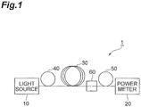
- Fig. 1 is a diagram showing an example of the device configuration upon measuring inter-core crosstalk of a multi-core optical fiber, and receiving light outputted from the multi-core optical fiber during measurement.
- a measurement beam is caused to enter only a specific core of the multi-core optical fiber to be measured, and it is necessary to measure the light emitted from that core or a specific core such as another core.
- the inter-core crosstalk measuring device 1 comprises a light source 10, a single-mode optical fiber 40 (light-transmitting optical fiber) that is optically connected to any one of the cores on an entrance end of the multi-core optical fiber 30 in which one end thereof is to be measured, a single-mode optical fiber 50 (light-receiving optical fiber as the light-receiving waveguide), an optical part 60 for optically connecting an emission end of the multi-core optical fiber 30 and the single-mode optical fiber 50, and a power meter 20.
- the multi-core optical fiber 30 to be measured is disposed between the light source 10 and the power meter 20.
- a single-mode optical fiber 40 is disposed on the entrance end side of the multi-core optical fiber 30 and a single-mode optical fiber 50 is disposed on the emission end side, respectively.
- the multi-core optical fiber 30 and the single-mode optical fiber 50 are connected via the optical part 60 for connecting the cores.
- optical waveguides or the like may be used in substitute for the single-mode optical fibers 40, 50.
- the single-core optical fiber or optical waveguide disposed at a latter stage (output end side) than the multi-core optical fiber 30 for guiding the light outputted from the multi-core optical fiber 30 to be measured is referred to as a light-receiving waveguide in the present embodiment.
- the single-mode optical fibers 40, 50 are made from a glass material in which its surface is covered by a coating.
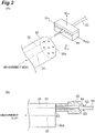
- the coupling of the cores of the multi-core optical fiber 30 and the single-mode optical fiber 40 can be realized, for example based on the configuration shown in Fig. 2 .
- Fig. 2(A) shows, as one example, the configuration of realizing non-contact optical coupling.
- Fig. 2(B) shows a configuration where the cores of the multi-core optical fiber 30 and the single-mode optical fiber 40 are fixed via an adhesive. Note that the measurement beam is introduced into the first core 31 of the multi-core optical fiber 30 to be measured.
- the single-mode optical fiber 50 is optically coupled to a second core 32 that is different from the first core 31 on the emission end face 30a in order to measure the inter-core crosstalk in the multi-core optical fiber 30 (light outputted from the second core 32 is guided through the single-mode optical fiber 50).
- a terminal portion of the single-mode optical fiber 50 is placed on a holder 61 configured from a lower member and an upper member with V-grooves formed therein.
- the holder 61 moves in the horizontal direction shown with arrows S 1a , S 1b in the diagram, and also moves in the vertical direction shown with arrows S 2a , S 2b in the diagram.
- the holder 61 to which one terminal portion of the single-mode optical fiber 50 is placed relatively moving the core of the single-mode optical fiber 50 relative to the second core 32 in the multi-core optical fiber 30, the second core 32 and the core of the single-mode optical fiber 50 are aligned in the multi-core optical fiber 30. Note that, in the example of Fig.
- the multi-core optical fiber 30 and the single-mode optical fiber 50 are retained without being bonded via an adhesive. Moreover, in the terminal portion of the single-mode optical fiber 50 including the end face facing the second core 32 of the multi-core optical fiber 30, a glass portion from which the coating has been removed is exposed (or the glass portion may be covered by the coating). A ferrule is not mounted on the terminal portion of the single-mode optical fiber 50. In accordance with this configuration, the light outputted from the second core 32 of the multi-core optical fiber 30 enters the core of the single-mode optical fiber 50 in a state where a ferrule is not mounted on the end thereof.
- a transparent ferrule 62 is mounted via an adhesive 64 on a terminal portion of the single-mode optical fiber 50 including an end face facing the second core 32 of the multi-core optical fiber 30 in a state where the glass portion from which the coating has been removed is exposed (the ferrule 62 moves along the terminal portion of the single-mode optical fiber 50 along arrow S3).
- the refractive index of the adhesive used for mounting the ferrule is higher than that of the cladding of the single-mode optical fiber 50.
- the light outputted from the second core 32 of the multi-core optical fiber 30 enters the core of the single-mode optical fiber 50 in a state where the transparent ferrule is mounted on the terminal portion thereof.
- E is a vector of an electric field
- H is a vector of a magnetic field
- the parameter having p as the index (subscript) is a component on the output side of the butt coupling
- the parameter having q as the index (subscript) is a component on the entrance side
- U z is a unit vector of light in the propagation direction.
- an actual single-mode optical fiber was used to examine the relation (coupling power profile) of the core axis displacement and the coupling power in a coupling portion in which single-core optical fibers (single-mode optical fibers: SMF) were coupled.
- the coupling power was normalized to be 0 dB when there is no axis displacement.
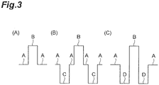
- Fig. 3 shows an example of the refractive index profile of a single-mode optical fiber.
- Fig. 3(A) shows a refractive index profile of a matched cladding type consisting of a core layer A and a core layer B having a refractive index higher than that of the cladding layer A
- Fig. 3(B) shows a refractive index profile of a trench-assisted type including a trench layer C having a low refractive index inside the cladding layer A
- Fig. 3(C) shows a refractive index profile of a depressed type refractive index profile including a depressed layer D between the cladding layer A and the core layer B.
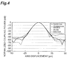
- Fig. 4 shows the coupling loss profile of the matched cladding type single-mode optical fibers
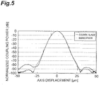
- Fig. 5 shows the coupling loss profile of the trench-assisted type single-mode optical fibers.
- “square glass,” “columnar glass with metal,” and “zirconia” respectively represent the material of the ferrule that is mounted on the terminal portion of the single-mode optical fiber 50.
- the "square glass” represents a bar-shaped glass ferrule having a square cross section
- the "columnar glass with metal” represents a glass ferrule in which a metal enclosure is mounted on the surface thereof
- zirconia represents a ferrule made from zirconia.
- a “bared fiber” represents a state where the coating on the terminal portion of the single-mode optical fiber 50 is removed and the glass portion is exposed.
- the portion of a clean single-peaked pattern and which is a portion that can be viewed in a range where the absolute value of the axis displacement is roughly 25 to 30 ⁇ m or less is the portion that can be explained with foregoing mathematical formulas (1) to (3).
- the wavy portion that can be viewed in a range where the absolute value of the axis displacement is greater than 25 to 30 ⁇ m is the portion that cannot be explained with the mathematical formulas (1) to (3).
- the reason why the portion of the single-peaked pattern is of a sharper shape in Fig. 5 in comparison to Fig. 4 is because the spread of the core propagation mode is smaller in the latter.
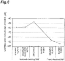
- Fig. 6 shows the average of the coupling power of the range (range that cannot be explained with the mathematical formulas (1) to (3)) of Figs. 4 and 5 in which the absolute value of the axis displacement is 30 to 50 ⁇ m.
- the average of the coupling power is high with respect to a fiber in the order of the matched cladding type single-mode optical fiber, and then the trench-assisted type single-mode optical fiber.
- a ferrule it can be seen that the average of the coupling power is high in the order of the zirconia ferrule, the glass ferrule (regardless of the shape or existence of a metal part), and then the bared fiber.
- the reduction of the average of the coupling power was considerable when the trench-assisted type single-mode optical fibers were butt-coupled in comparison to the case when the matched cladding type single-mode optical fibers were butt-coupled.
- the refractive index profile shape that is desirable as the light-receiving waveguide for use in a measuring system for measuring the inter-core crosstalk in a multi-core optical fiber to be measured includes the following features.
- a portion having a refractive index lower than that of a cladding exists between the core and the cladding such as trench-assisted type refractive index profile or depressed type refractive index profile.
- the trench layer or the depressed layer has a thickness and refractive index difference relative to the cladding which are sufficient for inhibiting the coupling from a cladding mode to a core mode.
- the radius (trench outer diameter) from the core center to the interface of the trench layer and the cladding layer, or the radius (depressed layer) to the interface of the depressed layer and the cladding layer should be as small as possible.
- the reason for this is because, when measuring the inter-core crosstalk in a multi-core optical fiber, most of the power of the output light from the coupling source core is coupled to the outside of the cladding outer diameter or the depressed outer diameter on the butted surface of the multi-core optical fiber and the light-receiving waveguide upon receiving the output light from the coupling destination core with the light-receiving waveguide. This aims to prevent a component, which should inhibit the coupling to the core of the light-receiving waveguide, from becoming coupled to the inside of the barrier to be inhibited.
- the terminal portion butted with the multi-core optical fiber 30 preferably includes the following features.
- the coating is removed and the glass portion is exposed.
- the refractive index of the coating is higher than that of the cladding and it is possible to cleanly cut the end face of the light-receiving optical fiber even with the coating remaining, the glass portion may be covered with a coating.
- the adherend of the light-receiving optical fiber and the ferrule needs to have an area of a certain size.
- the light-receiving optical fiber is in a state of being bonded to the ferrule.
- the ferrule is preferably composed of a material that transmits, without scattering, light of the wavelength band that is used for measurement so that the scattered light does not return to the light-receiving optical fiber.
- the ferrule and the adhesive for bonding the ferrule and the fiber have a refractive index that is higher than that of the cladding of the light-receiving optical fiber.
- the refractive index of the ferrule and the adhesive for bonding the ferrule and the light-receiving optical fiber is lower than that of the cladding of the light-receiving optical fiber
- the outside interface of the trap layer may be the interface of glass and air.
- Fig. 7(A) shows a trench-assisted type refractive index profile including a trap layer E
- Fig. 7(B) shows a depressed type refractive index profile including a trap layer E.
- a cladding layer A is provided to the outer periphery of the core layer B
- a trench layer C and a trap layer E are provided in the cladding layer A in order from the layer that is closest from the core B.
- a depressed layer D is provided between the core layer B and the cladding layer A
- a trap layer E is provided at a position in the cladding layer A and which is farther from the core layer B than the depressed layer D.
- the layer of a low refractive index can inhibit the propagation of noise and the like from the cladding side to the core. Consequently, even in cases where the inter-core crosstalk is small, it is possible to accurately measure the inter-core crosstalk since components that are different from crosstalk-derived components in optical power are reduced.
- the foregoing light-receiving waveguide may also have a plurality of cores, and the light-receiving method of the light outputted from the multi-core optical fiber of the present embodiment can also inhibit the inter-core crosstalk and extract signal light with low noise even upon simultaneously and individually extracting signal light from a plurality of cores of the multi-core fiber. Consequently, the present invention can also be suitably applied to a measuring method in which the influence of crosstalk other than the crosstalk measurement is a concern (for instance, measurement of transmission loss or cut-off wavelength), or the reception of signal light with light-receiving means relative to the multi-core optical fiber in the transmission system.
- the specific configuration of the light-receiving waveguide including the foregoing plurality of cores is shown in Fig. 8 .
- the light-receiving waveguide 70 shown in Fig. 8 comprises a plurality of single-core optical fibers 71 which respectively include a core 71a and satisfy the features of the present invention, and a plurality of single-core optical fibers 71 are bundled at one terminal portion thereof.
- the one terminal portion is formed as a ferrule or a connector in a state where the plurality of single-core optical fibers 71 are aligned to match the core arrangement of the multi-core optical fiber 30 ( Fig. 8 shows an example where one terminal portion is fixed by the ferrule 72).
- the light-receiving waveguide 70 shown in Fig. 8 is a fan-out device where the plurality of single-core optical fibers 71 are bundled at one terminal portion in a state of maintaining a predetermined arrangement, and the plurality of single-core optical fibers 71 are respectively separated at the other terminal portion.
- This kind of light-receiving waveguide 70 can also be used as the light-receiving waveguide for guiding the light outputted from the respective cores on the emission end face 30a of the multi-core optical fiber 30.
- 1 ...inter-core crosstalk measuring device; 10 ...light source; 20 ... power meter; 30 ... multi-core optical fiber; 40 ... single-mode optical fiber (light-transmitting waveguide); 50 ... single-mode optical fiber (light-receiving waveguide); 60 ... optical part; 61 ... holder; 62 ... ferrule; and 70 ... light-receiving waveguide.
Landscapes
- Physics & Mathematics (AREA)
- General Physics & Mathematics (AREA)
- Optics & Photonics (AREA)
- Chemical & Material Sciences (AREA)
- Analytical Chemistry (AREA)
- Optical Couplings Of Light Guides (AREA)
- Optical Integrated Circuits (AREA)
- Photometry And Measurement Of Optical Pulse Characteristics (AREA)
Description
- The present invention relates to a method of receiving light outputted from a multi-core optical fiber, and a separating apparatus of separating light outputted from a multi-core optical fiber.
- In recent years, multi-core optical fibers each including a plurality of cores are being actively researched. A multi-core optical fiber is configured, for example, by a plurality of cores being arranged two-dimensionally in a cross section orthogonal to a longitudinal direction thereof, and it is known that crosstalk is generated between such plurality of cores. The method of measuring inter-core crosstalk in such a multi-core optical fiber and a light-receiving method of receiving light outputted from the multi-core optical fiber during measurement are disclosed, for example, in
Non-patent Documents 1 to 3. Specifically, measurement of the crosstalk is performed as the measurement of the transfer rate of the optical power from the coupling source core to the coupling destination core.JP S62 47604 A JP S62 47604 A Claim 1. The publication KATSUHIRO TAKENAGA ET AL: "An Investigation on Crosstalk in Multi-Core Fibers by Introducing Random Fluctuation along Longitudinal Direction", DOI: 10.587/TRANSCOM.E94.B.409 discloses a method for measuring inter-core crosstalk of a multi-core optical fiber. The article does not, however, disclose the characterizing portion ofclaim 1. -
- Non-Patent Document 1: Proc. ECOC'10, We.8.F.6 (2010)
- Non-Patent Document 2: Proc. OFC'09 OTuc3 (2009)
- Non-Patent Document 3: Proc. OFC'10 OWK7 (2010)
- The present inventors have examined the above prior art, and as a result, have discovered the following problems. That is, when attempting to measure the crosstalk of a multi-core optical fiber in which the inter-core crosstalk caused by incident light propagation is extremely low, there are cases where accurate measurement cannot be performed since the noise light or the crosstalk during the coupling with the light-receiving optical fiber is larger. Specifically, when the coupling destination core and the core of the exit-side light-receiving optical fiber are aligned at the emission end of the multi-core optical fiber, output light from the coupling source core which is far more larger than the output light from the coupling destination core will enter the cladding of the light-receiving optical fiber. Here, depending on the state of the fiber end or the fiber structure, the light that entered the cladding of the light-receiving optical fiber is coupled with the core of the light-receiving optical fiber, and becomes noise during the measurement.
- The present invention has been developed to eliminate the problems described above. It is an object of the present invention to provide a light-receiving method of receiving light outputted from a multi-core optical fiber which enables the accurate measurement of inter-core crosstalk even when the inter-core crosstalk is small, as well as a separating apparatus.
- The present invention is defined by the appended
independent claims 1 and 5. The respective dependent claims describe optional features and preferred embodiments. A method of receiving light outputted from a multi-core optical fiber, as a first aspect, disposes a light-receiving waveguide having a unique structure on an emission end side of the multi-core optical fiber, causes a measurement beam to enter a first core on a first end face of the multi-core optical fiber, guides, through the light-receiving waveguide, light outputted from a second core that is different from the first core on a second end face opposing the first end face of the multi-core optical fiber, and receives the light that was guided through the light-receiving waveguide. Here, the light-receiving waveguide is disposed at a position where the light outputted from the multi-core optical fiber reaches, and is a waveguide for guiding the light outputted from the core of the multi-core optical fiber and having a refractive index structure of depressed type or trench-assisted type in which the core is surrounded by a layer having a refractive index lower than that of a cladding. - Note that the at least one of the depressed layer constituting the depressed type and the trench layer constituting the trench-assisted type does not need to be configured entirely from a solid, and may also be a structure where the average refractive index is lower than that of the cladding due to a hole.
- In accordance with the light-receiving method according to the first aspect, as a result of using a depressed type or trench-assisted type light-receiving waveguide in which the core is surrounded by the layer having a refractive index lower than that of a cladding as light-receiving means for receiving the light outputted from the multi-core optical fiber, the layer of the low refractive index can inhibit the propagation of noise and the like from the cladding to the core. Consequently, even in cases where multi-core optical fiber with as small inter-core crosstalk is measured, it is possible to accurately measure the inter-core crosstalk since components that are different from crosstalk-derived components in optical power are reduced.
- Here, as a configuration which effectively yields the foregoing effect (as a second aspect that can be applied to the first aspect), the following aspect may be adopted. Specifically, the light-receiving waveguide includes a light-receiving optical fiber composed of a glass material in which its surface is covered with a coating. After the second core of the multi-core optical fiber and a core of the light-receiving optical fiber are aligned, the multi-core optical fiber and the light-receiving optical fiber are retained without being bonded with an adhesive. In a terminal portion of the light-receiving optical fiber including an end face facing the second core of the multi-core optical fiber, a glass portion from which the coating has been removed is exposed, or the glass portion is covered by the coating. In the second aspect, the light outputted from the second core of the multi-core optical fiber enters the core of the light-receiving optical fiber in a state where a ferrule is not mounted on the terminal portion of the light-receiving optical fiber.
- As another configuration which effectively yields the foregoing effect, the following aspect (a third aspect that can be applied to the first aspect) can be adopted. Specifically, the light-receiving waveguide includes a light-receiving optical fiber composed of a glass material in which its surface is covered with a coating. After the second core of the multi-core optical fiber and a core of the light-receiving optical fiber are aligned, the multi-core optical fiber and the light-receiving optical fiber are bonded with an adhesive. A transparent ferrule is mounted via an adhesive on a terminal portion of the light-receiving optical fiber including an end face facing the second core of the multi-core optical fiber in a state where the glass portion from which the coating has been removed is exposed. Note that the refractive index of the adhesive used for mounting the ferrule is higher than that of the cladding of the light-receiving optical fiber. In the third aspect, the light outputted from the second core of the multi-core optical fiber enters the core of the light-receiving optical fiber in a state where the transparent ferrule is mounted on the terminal portion of the light-receiving optical fiber.
- Moreover, the light-receiving method of receiving light outputted from a multi-core optical fiber according to the present invention, as a fourth aspect, disposes a light-receiving waveguide having a unique structure on an emission end side of the multi-core optical fiber, causes a measurement beam or signal light to enter one or more cores on a first end face of the multi-core optical fiber, separates the light outputted from the respective cores on a second end face by guiding, through the light-receiving waveguide, the light outputted from the respective cores on the second end face opposing the first end face of the multi-core optical fiber, and individually receives the light that was guided through the plurality of cores of light-receiving waveguide.
- In the fourth aspect, and according to the present invention, the light-receiving waveguide is disposed at a position where the light outputted from the multi-core optical fiber reaches, and is a waveguide for guiding the light outputted from a core of the multi-core optical fiber and having a refractive index structure of depressed type or trench-assisted type which includes a plurality of cores and in which each of the cores is surrounded by a layer having a refractive index lower than that of a cladding. Moreover, at least one of the depressed layer and the trench layer is constituted by only solid having a refractive index lower than that of the cladding, or formed as a layer in which an average refractive index is lower than that of the cladding as a result of including a hole in the solid.
- As a fifth aspect that can be applied to the fourth aspect, the light-receiving waveguide may have a refractive index structure including a trap layer which has a refractive index higher than that of the cladding and which is positioned further toward an outer side than the depressed layer or the trench layer.
- Moreover, as the fifth aspect, the separating apparatus of separating light outputted from a multi-core optical fiber according to the present invention comprises a light-receiving waveguide for guiding light outputted from a core of the multi-core optical fiber. The light-receiving waveguide having a unique structure and disposed at a position where light outputted from the multi-core optical fiber will reach. The light-receiving waveguide has a refractive index structure of depressed type or trench-assisted type which includes a plurality of cores and in which each of the cores is surrounded by a layer having a refractive index lower than that of a cladding. Moreover, at least one of the depressed layer and the trench layer is constituted by only solid having a refractive index lower than that of the cladding, or may be formed as a layer in which an average refractive index is lower than that of the cladding as a result of including a hole in the solid.
- In the fifth aspect, a measurement beam or signal light enters one or more cores on a first end face of the multi-core optical fiber. The light outputted from the respective cores on a second end face is separated by guiding, through the light-receiving waveguide, the light outputted from the respective cores on the second end face opposing the first end face of the multi-core optical fiber. Consequently, the light that was guided through the plurality of cores of light-receiving waveguide is individually received.
- As a configuration which effectively yields the effect of the fifth aspect, the following aspect (a sixth aspect that can be applied to the fifth aspect) may be adopted. Specifically, the light-receiving waveguide is configured from a plurality of single-core optical fibers in which terminal portions on one side thereof are bundled. The bundled terminal portion of the light-receiving waveguide is constituted as a ferrule or a connector in a state where the plurality of single-core optical fibers are aligned to match the core arrangement of the multi-core fiber. Meanwhile, the other terminal portion of the light-receiving waveguide allows the plurality of single-core optical fibers to be individually separated.
- In accordance with the present invention, it is possible to provide a light-receiving method of receiving light outputted from a multi-core optical fiber which enables the accurate measurement of the inter-core crosstalk even in cases of measuring a multi-core optical fiber having small inter-core crosstalk.
-
-
Fig. 1 is a diagram showing an example of the device configuration upon measuring inter-core crosstalk of a multi-core optical fiber, and receiving light outputted from the multi-core optical fiber during measurement; -
Fig. 2 shows diagrams explaining the optically connected state of the multi-core optical fiber and the light-receiving optical fiber; -
Fig. 3 shows diagrams showing an example of the refractive index profile of the light-receiving optical fiber; -
Fig. 4 is a coupling power profile when coupling the matched cladding type single-mode optical fibers; -
Fig. 5 is a coupling power profile upon coupling the trench-assisted type single-mode optical fibers; -
Fig. 6 is a diagram showing the normalized light-receiving power average in which the absolute value of the axis displacement is in a range of 30 to 50 µm; -
Fig. 7 shows diagrams explaining the refractive index profiles of the trench-assisted type structure and the depressed type structure having a trap layer, as the refractive index profile of the light-receiving optical fiber; and -
Fig. 8 is a diagram explaining an example of the configuration of a light-receiving waveguide. - In the following, the preferred embodiments for implementing the present invention will be explained in detail with reference to the appended drawings. Note that the same elements in the explanation of the drawings are given the same reference numeral and the redundant explanation thereof is omitted.
-
Fig. 1 is a diagram showing an example of the device configuration upon measuring inter-core crosstalk of a multi-core optical fiber, and receiving light outputted from the multi-core optical fiber during measurement. When measuring the inter-core crosstalk of a multi-core optical fiber, a measurement beam is caused to enter only a specific core of the multi-core optical fiber to be measured, and it is necessary to measure the light emitted from that core or a specific core such as another core. Thus, as shown inFig. 1 , the inter-corecrosstalk measuring device 1 comprises alight source 10, a single-mode optical fiber 40 (light-transmitting optical fiber) that is optically connected to any one of the cores on an entrance end of the multi-coreoptical fiber 30 in which one end thereof is to be measured, a single-mode optical fiber 50 (light-receiving optical fiber as the light-receiving waveguide), anoptical part 60 for optically connecting an emission end of the multi-coreoptical fiber 30 and the single-modeoptical fiber 50, and apower meter 20. Specifically, in themeasuring device 1, as one example, the multi-coreoptical fiber 30 to be measured is disposed between thelight source 10 and thepower meter 20. A single-modeoptical fiber 40 is disposed on the entrance end side of the multi-coreoptical fiber 30 and a single-modeoptical fiber 50 is disposed on the emission end side, respectively. The multi-coreoptical fiber 30 and the single-modeoptical fiber 50 are connected via theoptical part 60 for connecting the cores. Moreover, optical waveguides or the like may be used in substitute for the single-modeoptical fibers - Here, the single-core optical fiber or optical waveguide disposed at a latter stage (output end side) than the multi-core
optical fiber 30 for guiding the light outputted from the multi-coreoptical fiber 30 to be measured is referred to as a light-receiving waveguide in the present embodiment. Moreover, the single-modeoptical fibers - The coupling of the cores of the multi-core
optical fiber 30 and the single-modeoptical fiber 40 can be realized, for example based on the configuration shown inFig. 2 . Fig. 2(A) shows, as one example, the configuration of realizing non-contact optical coupling. Moreover, the example of Fig. 2(B) shows a configuration where the cores of the multi-coreoptical fiber 30 and the single-modeoptical fiber 40 are fixed via an adhesive. Note that the measurement beam is introduced into thefirst core 31 of the multi-coreoptical fiber 30 to be measured. The single-modeoptical fiber 50 is optically coupled to asecond core 32 that is different from thefirst core 31 on theemission end face 30a in order to measure the inter-core crosstalk in the multi-core optical fiber 30 (light outputted from thesecond core 32 is guided through the single-mode optical fiber 50). - In Fig. 2(A), a terminal portion of the single-mode
optical fiber 50 is placed on aholder 61 configured from a lower member and an upper member with V-grooves formed therein. Theholder 61 moves in the horizontal direction shown with arrows S1a, S1b in the diagram, and also moves in the vertical direction shown with arrows S2a, S2b in the diagram. As a result of theholder 61 to which one terminal portion of the single-modeoptical fiber 50 is placed relatively moving the core of the single-modeoptical fiber 50 relative to thesecond core 32 in the multi-coreoptical fiber 30, thesecond core 32 and the core of the single-modeoptical fiber 50 are aligned in the multi-coreoptical fiber 30. Note that, in the example of Fig. 2(A), after the alignment, the multi-coreoptical fiber 30 and the single-modeoptical fiber 50 are retained without being bonded via an adhesive. Moreover, in the terminal portion of the single-modeoptical fiber 50 including the end face facing thesecond core 32 of the multi-coreoptical fiber 30, a glass portion from which the coating has been removed is exposed (or the glass portion may be covered by the coating). A ferrule is not mounted on the terminal portion of the single-modeoptical fiber 50. In accordance with this configuration, the light outputted from thesecond core 32 of the multi-coreoptical fiber 30 enters the core of the single-modeoptical fiber 50 in a state where a ferrule is not mounted on the end thereof. - Meanwhile, in Fig. \2(B), after the
second core 32 of the multi-coreoptical fiber 30 and the core of the single-mode optical fiberoptical fiber 50 are aligned, the multi-coreoptical fiber 30 and the single-modeoptical fiber 50 are bonded via an adhesive 63. Subsequently, atransparent ferrule 62 is mounted via an adhesive 64 on a terminal portion of the single-modeoptical fiber 50 including an end face facing thesecond core 32 of the multi-coreoptical fiber 30 in a state where the glass portion from which the coating has been removed is exposed (theferrule 62 moves along the terminal portion of the single-modeoptical fiber 50 along arrow S3). Note that the refractive index of the adhesive used for mounting the ferrule is higher than that of the cladding of the single-modeoptical fiber 50. In accordance with this configuration, the light outputted from thesecond core 32 of the multi-coreoptical fiber 30 enters the core of the single-modeoptical fiber 50 in a state where the transparent ferrule is mounted on the terminal portion thereof. - Considered is a case of disposing the light-receiving waveguide at a latter stage of the multi-core
optical fiber 30 and causing the measurement beam outputted from the multi-coreoptical fiber 30 through the light-receiving waveguide, and thereby measuring the inter-core crosstalk in a multi-core optical fiber in which the inter-core crosstalk arising during the propagation of the measurement beam is extremely small. Under the foregoing conditions, it was confirmed that crosstalk that is greater than the inter-core crosstalk based on the propagation of light that is expected from a theoretical value could be measured. In addition, the present inventors discovered that this value cannot be explained even upon giving consideration to the inter-core crosstalk in a coupling portion of a multi-core optical fiber and a light-receiving waveguide that is expected from the following mathematical formula (1), which is a conventional formula of the coupling efficiency of butt-coupling (Katsunari Okamoto, Fundamentals of Optical Waveguides, Corona Publishing).
- Note that, in the foregoing mathematical formula (1), E is a vector of an electric field, H is a vector of a magnetic field, the parameter having p as the index (subscript) is a component on the output side of the butt coupling, the parameter having q as the index (subscript) is a component on the entrance side, and Uz is a unit vector of light in the propagation direction.
- When the foregoing mathematical formula (1) is simply rewritten based on an electric field of a scalar display, the following mathematical formula (2) is obtained, and the coupling coefficient of the optical intensity can be represented as the following mathematical formula (3).


- Normally, in a single-mode optical fiber, the electric field distribution of the fundamental-mode monotonically decreases as it becomes separated from the center of the core.
- Here, in order to examine the crosstalk in a coupling portion of a multi-core optical fiber and a light-receiving waveguide in which the inter-core crosstalk during the propagation of light is extremely small and can be ignored, an actual single-mode optical fiber was used to examine the relation (coupling power profile) of the core axis displacement and the coupling power in a coupling portion in which single-core optical fibers (single-mode optical fibers: SMF) were coupled. The coupling power was normalized to be 0 dB when there is no axis displacement.
-
Fig. 3 shows an example of the refractive index profile of a single-mode optical fiber. Fig. 3(A) shows a refractive index profile of a matched cladding type consisting of a core layer A and a core layer B having a refractive index higher than that of the cladding layer A, Fig. 3(B) shows a refractive index profile of a trench-assisted type including a trench layer C having a low refractive index inside the cladding layer A, and Fig. 3(C) shows a refractive index profile of a depressed type refractive index profile including a depressed layer D between the cladding layer A and the core layer B. In addition,Fig. 4 shows the coupling loss profile of the matched cladding type single-mode optical fibers, andFig. 5 shows the coupling loss profile of the trench-assisted type single-mode optical fibers. - Here, in
Figs. 4 and5 , "square glass," "columnar glass with metal," and "zirconia" respectively represent the material of the ferrule that is mounted on the terminal portion of the single-modeoptical fiber 50. Specifically, the "square glass" represents a bar-shaped glass ferrule having a square cross section, the "columnar glass with metal" represents a glass ferrule in which a metal enclosure is mounted on the surface thereof, and "zirconia" represents a ferrule made from zirconia. Moreover, a "bared fiber" represents a state where the coating on the terminal portion of the single-modeoptical fiber 50 is removed and the glass portion is exposed. - In both
Figs. 4 and5 , the portion of a clean single-peaked pattern and which is a portion that can be viewed in a range where the absolute value of the axis displacement is roughly 25 to 30 µm or less is the portion that can be explained with foregoing mathematical formulas (1) to (3). Meanwhile, the wavy portion that can be viewed in a range where the absolute value of the axis displacement is greater than 25 to 30 µm is the portion that cannot be explained with the mathematical formulas (1) to (3). The reason why the portion of the single-peaked pattern is of a sharper shape inFig. 5 in comparison toFig. 4 is because the spread of the core propagation mode is smaller in the latter. - Here,
Fig. 6 shows the average of the coupling power of the range (range that cannot be explained with the mathematical formulas (1) to (3)) ofFigs. 4 and5 in which the absolute value of the axis displacement is 30 to 50 µm. - In accordance with the results of
Fig. 6 , the average of the coupling power is high with respect to a fiber in the order of the matched cladding type single-mode optical fiber, and then the trench-assisted type single-mode optical fiber. Regarding a ferrule, it can be seen that the average of the coupling power is high in the order of the zirconia ferrule, the glass ferrule (regardless of the shape or existence of a metal part), and then the bared fiber. Among the above, it was confirmed that the reduction of the average of the coupling power was considerable when the trench-assisted type single-mode optical fibers were butt-coupled in comparison to the case when the matched cladding type single-mode optical fibers were butt-coupled. - The reasons why the foregoing results were obtained can be qualitatively explained as follows.
- (A) Foremost, foregoing mathematical formulas (1) to (3) represent the coupling that occurs at only butted portion of the fiber end face. However, in reality, when the axis displacement increases, the coupling power to the core of the output-side optical fiber based on the butt-coupling will decrease, and most of the power will be coupled to the cladding. While the propagation mode of the cladding is unstable and the propagation loss is great, there is coupling while propagating from the cladding modes to the core mode, and this can be ignored when the coupling to the core in the butt-coupling is large, but cannot be ignored when the coupling to the core in the butt-coupling is small.
- (B) Moreover, with the trench-assisted type single-mode optical fiber, since a trench layer having a lower refractive index exists around the core, the trench layer acts as a barrier and inhibits the coupling from the cladding modes to the core mode.
- (C) The light that should have escaped outside the cladding is scattered or reflected to the ferrule or the adhesive used for bonding the ferrule and the optical fiber. Thus, the light that should have escaped outside the cladding is trapped in the cladding, and the power of light that is coupled from the cladding mode to the core mode is increased.
- Based on the foregoing analysis, it was confirmed that the refractive index profile shape that is desirable as the light-receiving waveguide for use in a measuring system for measuring the inter-core crosstalk in a multi-core optical fiber to be measured includes the following features.
- (1) A portion having a refractive index lower than that of a cladding exists between the core and the cladding such as trench-assisted type refractive index profile or depressed type refractive index profile.
- (2) The trench layer or the depressed layer has a thickness and refractive index difference relative to the cladding which are sufficient for inhibiting the coupling from a cladding mode to a core mode.
- (3) In the foregoing premise, the radius (trench outer diameter) from the core center to the interface of the trench layer and the cladding layer, or the radius (depressed layer) to the interface of the depressed layer and the cladding layer should be as small as possible. The reason for this is because, when measuring the inter-core crosstalk in a multi-core optical fiber, most of the power of the output light from the coupling source core is coupled to the outside of the cladding outer diameter or the depressed outer diameter on the butted surface of the multi-core optical fiber and the light-receiving waveguide upon receiving the output light from the coupling destination core with the light-receiving waveguide. This aims to prevent a component, which should inhibit the coupling to the core of the light-receiving waveguide, from becoming coupled to the inside of the barrier to be inhibited.
- Moreover, when the light-receiving waveguide is an optical fiber (light-receiving optical fiber), the terminal portion butted with the multi-core
optical fiber 30 preferably includes the following features. - (4) When it is not necessary to bond the multi-core optical fiber and the light-receiving optical fiber (when performing fusion or performing measurement on an aligning machine), desirably the coating is removed and the glass portion is exposed. However, if the refractive index of the coating is higher than that of the cladding and it is possible to cleanly cut the end face of the light-receiving optical fiber even with the coating remaining, the glass portion may be covered with a coating.
- (5) When it is necessary to bond the multi-core optical fiber and the light-receiving optical fiber, the adherend of the light-receiving optical fiber and the ferrule needs to have an area of a certain size. Thus, preferably, the light-receiving optical fiber is in a state of being bonded to the ferrule. Moreover, the ferrule is preferably composed of a material that transmits, without scattering, light of the wavelength band that is used for measurement so that the scattered light does not return to the light-receiving optical fiber. In addition, so that the power of the cladding mode can easily escape to the ferrule, the ferrule and the adhesive for bonding the ferrule and the fiber have a refractive index that is higher than that of the cladding of the light-receiving optical fiber.
- (6) When the refractive index of the ferrule and the adhesive for bonding the ferrule and the light-receiving optical fiber is lower than that of the cladding of the light-receiving optical fiber, it is also possible to provide, in the cladding on the outside of the trench interface or the depressed interface, a layer (trap layer) having a refractive index higher than that of the cladding, and couple the cladding mode to the trap layer. Here, even if a cladding is further provided outside the trap layer, the outside interface of the trap layer may be the interface of glass and air. An example of the refractive index profile of the light-receiving optical fiber provided with a trap layer is shown in
Fig. 7 . Fig. 7(A) shows a trench-assisted type refractive index profile including a trap layer E, and Fig. 7(B) shows a depressed type refractive index profile including a trap layer E. Note that, in the refractive index profile of Fig. 7(A), a cladding layer A is provided to the outer periphery of the core layer B, and a trench layer C and a trap layer E are provided in the cladding layer A in order from the layer that is closest from the core B. Moreover, in the refractive index profile of Fig. 7(B), a depressed layer D is provided between the core layer B and the cladding layer A, and a trap layer E is provided at a position in the cladding layer A and which is farther from the core layer B than the depressed layer D. - As described above, in accordance with the light-receiving method of receiving the light outputted from the multi-core optical fiber of the present embodiment, as a result of using a depressed type or trench-assisted type light-receiving waveguide in which the core is surrounded by a layer having a refractive index lower than that of a cladding as light-receiving means for receiving light outputted from a multi-core optical fiber, the layer of a low refractive index can inhibit the propagation of noise and the like from the cladding side to the core. Consequently, even in cases where the inter-core crosstalk is small, it is possible to accurately measure the inter-core crosstalk since components that are different from crosstalk-derived components in optical power are reduced.
- Explanation mainly related to the measurement of the crosstalk was provided above, but the foregoing light-receiving waveguide may also have a plurality of cores, and the light-receiving method of the light outputted from the multi-core optical fiber of the present embodiment can also inhibit the inter-core crosstalk and extract signal light with low noise even upon simultaneously and individually extracting signal light from a plurality of cores of the multi-core fiber. Consequently, the present invention can also be suitably applied to a measuring method in which the influence of crosstalk other than the crosstalk measurement is a concern (for instance, measurement of transmission loss or cut-off wavelength), or the reception of signal light with light-receiving means relative to the multi-core optical fiber in the transmission system.
- The specific configuration of the light-receiving waveguide including the foregoing plurality of cores is shown in
Fig. 8 . The light-receivingwaveguide 70 shown inFig. 8 comprises a plurality of single-coreoptical fibers 71 which respectively include acore 71a and satisfy the features of the present invention, and a plurality of single-coreoptical fibers 71 are bundled at one terminal portion thereof. The one terminal portion is formed as a ferrule or a connector in a state where the plurality of single-coreoptical fibers 71 are aligned to match the core arrangement of the multi-core optical fiber 30 (Fig. 8 shows an example where one terminal portion is fixed by the ferrule 72). Meanwhile, at the other terminal portion of the light-receivingwaveguide 70, the single-core optical fibers are separated one by one. The light-receivingwaveguide 70 shown inFig. 8 is a fan-out device where the plurality of single-coreoptical fibers 71 are bundled at one terminal portion in a state of maintaining a predetermined arrangement, and the plurality of single-coreoptical fibers 71 are respectively separated at the other terminal portion. This kind of light-receivingwaveguide 70 can also be used as the light-receiving waveguide for guiding the light outputted from the respective cores on theemission end face 30a of the multi-coreoptical fiber 30. - 1 ...inter-core crosstalk measuring device; 10 ...light source; 20 ... power meter; 30 ... multi-core optical fiber; 40 ... single-mode optical fiber (light-transmitting waveguide); 50 ... single-mode optical fiber (light-receiving waveguide); 60 ... optical part; 61 ... holder; 62 ... ferrule; and 70 ... light-receiving waveguide.
Claims (8)
- A method of measuring inter-core crosstalk of a multi-core optical fiber (30), the method comprising the steps of:disposing, at a position where light outputted from the multi-core optical fiber (30) reaches, a light-receiving waveguide (50; 70) which guides light outputted from one or more cores of the multi-core optical fiber (30),causing light to enter at least a first core (31) on a first end face of the multi-core optical fiber (30);guiding light outputted from at least a second core (32) on a second end face opposing the first end face of the multi-core optical fiber (30) through the light-receiving waveguide (50; 70), the second core (32) being different from the first core (31);receiving the light having been guided through the light-receiving waveguide (50; 70), andmeasuring the light having been guided through the light-receiving waveguide (50; 70) with a power meter;characterized in that:the light-receiving waveguide (50; 70) has one or more cores and a cladding (A), and a refractive index structure of depressed type or trench-assisted type in which each core (B) is surrounded by a layer (C; D) having a refractive index lower than that of the cladding (A),the layer (C; D) constituting the depressed type or the trench-assisted type is positioned inside the cladding (A) or between the cladding (A) and the core (B), andthe layer (C; D) constituting the depressed type or the trench-assisted type is constituted by only solid having a refractive index lower than that of the cladding (A), or formed as a layer in which an average refractive index thereof is lower than that of the cladding (A) as a result of having holes in the solid.
- The method according to claim 1, wherein the light-receiving waveguide (50) includes a light-receiving optical fiber composed of a glass material in which a surface thereof is covered with a coating,wherein, after the second core (32) of the multi-core optical fiber (30) and a core of the light-receiving optical fiber are aligned, the multi-core optical fiber (30) and the light-receiving optical fiber are retained without being bonded with an adhesive,wherein, in a terminal portion of the light-receiving optical fiber including an end face facing the second core (32) of the multi-core optical fiber (30), a glass portion from which the coating has been removed is exposed, or the glass portion is covered by the coating, andwherein the light outputted from the second core (32) of the multi-core optical fiber (30) enters the core of the light-receiving optical fiber in a state where a ferrule (61) is not mounted on the terminal portion of the light-receiving optical fiber.
- The method according to claim 1, wherein the light-receiving waveguide (50) includes a light-receiving optical fiber composed of a glass material in which a surface thereof is covered with a coating,wherein, after the second core (32) of the multi-core optical fiber (30) and a core of the light-receiving optical fiber are aligned, the multi-core optical fiber (30) and the light-receiving optical fiber are bonded with an adhesive,
wherein a transparent ferrule (62) is mounted via the adhesive on a terminal portion of the light-receiving optical fiber including an end face facing the second core (32) of the multi-core optical fiber (30) in a state where the glass portion from which the coating has been removed is exposed,wherein the refractive index of the adhesive used for mounting the ferrule (62) is higher than that of the cladding of the light-receiving optical fiber, andwherein the light outputted from the second core (32) of the multi-core optical fiber (30) enters the core of the light-receiving optical fiber in a state where the transparent ferrule (62) is mounted on the terminal portion of the light- receiving optical fiber. - The method according to claim 1, wherein the light-receiving waveguide (50; 70) has a refractive index structure including a trap layer (E) which has a refractive index higher than that of the cladding (A) and which is positioned further toward an outer side than the layer (C; D) constituting the depressed type or the trench-assisted type.
- A device (1) for measuring inter-core crosstalk of a multi-core optical fiber (30), the device comprising:a light source (10) outputting light to the multi-core optical fiber (30);a separating apparatus comprising a light-receiving waveguide (70) which guides light outputted from cores of the multi-core optical fiber (30); anda power meter (20) receiving light having been guided through the light-receiving waveguide (70),the light-receiving waveguide (70) is disposed at a position where light outputted from the multi-core optical fiber (30) reaches,wherein the light outputted from the light source (10) enters one or more cores on a first end face of the multi-core optical fiber (30), andlight outputted from the respective cores on a second end face of the multi-core optical fiber (30) is separated by guiding the outputted light through the light-receiving waveguide (70), the second end face opposing the first end face of the multi-core optical fiber (30),characterized in thatthe light-receiving waveguide (70) has a plurality of cores (71a) and a cladding (A), and a refractive index structure of depressed type or trench-assisted type in which each of the cores is surrounded by a layer (C; D) having a refractive index lower than that of the cladding (A),the layer (C; D) constituting the depressed type or the trench-assisted type is positioned inside the cladding (A) or between the cladding (A) and the core (B),the layer (C; D) constituting the depressed type or the trench- assisted type is constituted by only solid having a refractive index lower than that of the cladding (A), or formed as a layer in which an average refractive index thereof is lower than that of the cladding (A) as a result of having holes in the solid.
- The device (1) according to claim 5, wherein, after the cores of the multi-core optical fiber (30) and the cores (71a) of the light-receiving waveguide (70) are aligned, the multi-core optical fiber (30) and the light-receiving waveguide (70) are bonded with an adhesive,wherein, the light receiving waveguide (50) includes a light receiving optical fiber composed of a glass material in which a surface thereof is covered with a coating,wherein a transparent ferrule (62) is mounted via the adhesive on a terminal portion of the light receiving optical fiber including an end face facing the second core (32) of the multi core optical fiber (30) in a state where the glass portion from which the coating has been removed is exposed,wherein the refractive index of the adhesive used for mounting the ferrule (62) is higher than that of the cladding of the light receiving optical fiber, andwherein the light outputted from the second core (32) of the multi core optical fiber (30) enters the core of the light receiving optical fiber in a state where the transparent ferrule (62) is mounted on the terminal portion of the light receiving optical fiber.
- The device (1) according to claim 5, wherein the light-receiving waveguide (70) has a refractive index structure including a trap layer (E) which has a refractive index higher than that of the cladding (A) and which is positioned further toward an outer side than the layer (C: D) constituting the depressed type or the trench-assisted type.
- The device (1) according to any one of claims 5 to 7, wherein the light-receiving waveguide (70) is configured from a plurality of single-core optical fibers (71) in which terminal portions on one side (72) thereof is bundled, the bundled terminal portions are constituted as a ferrule or a connector in a state where the plurality of single-core optical fibers (71) are aligned to match the core arrangement of the multi-core optical fiber, and terminal portions on the other side allow the plurality of single-core optical fibers (71) to be individually separated.
Applications Claiming Priority (3)
| Application Number | Priority Date | Filing Date | Title |
|---|---|---|---|
| JP2011040526 | 2011-02-25 | ||
| JP2012000258A JP5910087B2 (en) | 2011-02-25 | 2012-01-04 | Light receiving method and separation device for light output from multi-core optical fiber |
| PCT/JP2012/054306 WO2012115162A1 (en) | 2011-02-25 | 2012-02-22 | Light receiving method for light output from multi-core optical fiber, and separation apparatus |
Publications (3)
| Publication Number | Publication Date |
|---|---|
| EP2679977A1 EP2679977A1 (en) | 2014-01-01 |
| EP2679977A4 EP2679977A4 (en) | 2018-05-02 |
| EP2679977B1 true EP2679977B1 (en) | 2022-06-15 |
Family
ID=46720937
Family Applications (1)
| Application Number | Title | Priority Date | Filing Date |
|---|---|---|---|
| EP12749190.0A Active EP2679977B1 (en) | 2011-02-25 | 2012-02-22 | Method and device for measuring inter-core crosstalk of a multi-core optical fiber |
Country Status (6)
| Country | Link |
|---|---|
| US (2) | US8923668B2 (en) |
| EP (1) | EP2679977B1 (en) |
| JP (1) | JP5910087B2 (en) |
| CN (1) | CN103392120B (en) |
| DK (1) | DK2679977T3 (en) |
| WO (1) | WO2012115162A1 (en) |
Families Citing this family (21)
| Publication number | Priority date | Publication date | Assignee | Title |
|---|---|---|---|---|
| JP2011237782A (en) * | 2010-04-13 | 2011-11-24 | Sumitomo Electric Ind Ltd | Optical branch element and optical communication system including the same |
| JP5910087B2 (en) * | 2011-02-25 | 2016-04-27 | 住友電気工業株式会社 | Light receiving method and separation device for light output from multi-core optical fiber |
| JP5491440B2 (en) * | 2011-03-29 | 2014-05-14 | 日本電信電話株式会社 | Fan-out parts for multi-core fiber |
| US9513189B2 (en) * | 2012-11-08 | 2016-12-06 | Ofs Fitel, Llc | Device and method to measure the DMD and other parameters of a multicore optical fiber |
| WO2014123873A1 (en) * | 2013-02-05 | 2014-08-14 | Commscope, Inc. Of North Carolina | Methods of connectorizing multi-core fiber optic cables and related apparatus |
| JP5517228B1 (en) * | 2013-04-16 | 2014-06-11 | 日本電信電話株式会社 | Method and system for evaluating crosstalk characteristics of multi-core optical fiber |
| JP5801926B1 (en) * | 2014-05-29 | 2015-10-28 | 日本電信電話株式会社 | Crosstalk measuring apparatus and measuring method for optical fiber amplifier |
| JP5948368B2 (en) * | 2014-06-05 | 2016-07-06 | 株式会社フジクラ | Optical fiber characterization method |
| JP6341788B2 (en) * | 2014-07-28 | 2018-06-13 | シチズン時計株式会社 | Optical fiber connector, optical module, and manufacturing method |
| WO2016106714A1 (en) * | 2014-12-31 | 2016-07-07 | 华为技术有限公司 | Data transmission method, apparatus and system |
| WO2017090616A1 (en) * | 2015-11-26 | 2017-06-01 | 日本電信電話株式会社 | Transmission quality estimation system, transmission quality estimation device, and transmission quality estimation method |
| JP6654104B2 (en) | 2016-02-26 | 2020-02-26 | 株式会社フジクラ | Method and apparatus for measuring crosstalk of multi-core fiber |
| KR20240035639A (en) * | 2016-05-11 | 2024-03-15 | 인튜어티브 서지컬 오퍼레이션즈 인코포레이티드 | Redundant core in multicore optical fiber for safety |
| JP6862712B2 (en) * | 2016-08-05 | 2021-04-21 | 住友電気工業株式会社 | Optical fiber evaluation method and optical fiber evaluation device |
| TWI636617B (en) | 2016-12-23 | 2018-09-21 | 財團法人工業技術研究院 | Electromagnetic wave transmitting board differential electromagnetic wave transmitting board |
| CN108254830B (en) * | 2016-12-29 | 2020-06-02 | 中国电子科技集团公司第三十四研究所 | Method for testing insertion loss of optical fiber buncher |
| JP2018138910A (en) * | 2017-02-24 | 2018-09-06 | 株式会社フジクラ | Device and method for measuring characteristics of multi-core fiber |
| EP3562064A1 (en) * | 2018-04-27 | 2019-10-30 | Institut Mines-Telecom | Methods and devices for the determination of core dependent loss in multi-core fiber transmission systems |
| CN109633828B (en) * | 2019-02-21 | 2024-05-14 | 浙江富春江光电科技有限公司 | Mounting structure of multicore fiber array |
| CN112697402B (en) * | 2020-12-15 | 2021-10-26 | 长飞光纤光缆股份有限公司 | Multi-core optical fiber testing method and device |
| CN112733073A (en) * | 2020-12-30 | 2021-04-30 | 中天通信技术有限公司 | Multi-core optical fiber crosstalk detection method based on coupling power theory |
Citations (1)
| Publication number | Priority date | Publication date | Assignee | Title |
|---|---|---|---|---|
| EP0783117A2 (en) * | 1996-01-04 | 1997-07-09 | Nippon Telegraph And Telephone Corporation | Optical fibers for optical attenuation |
Family Cites Families (17)
| Publication number | Priority date | Publication date | Assignee | Title |
|---|---|---|---|---|
| JPS57191798A (en) | 1981-05-19 | 1982-11-25 | Furukawa Electric Co Ltd | Detection of value to be measured employing multi-core optical fiber |
| CA1273816A (en) * | 1985-05-24 | 1990-09-11 | Masatoshi Kaneshi | Method of the measurement of light from an optical cable and arrangement therefor |
| JPS6247604A (en) * | 1985-08-27 | 1987-03-02 | Furukawa Electric Co Ltd:The | Terminal part for multicore fiber |
| JPS6349707A (en) | 1986-08-20 | 1988-03-02 | Sumitomo Electric Ind Ltd | Optical fiber for communication |
| GB8816521D0 (en) * | 1988-07-12 | 1988-08-17 | British Telecomm | Optical star couplers |
| JP3271886B2 (en) * | 1996-01-04 | 2002-04-08 | 日本電信電話株式会社 | Optical attenuating optical fiber |
| JP3461707B2 (en) * | 1997-12-10 | 2003-10-27 | 株式会社フジクラ | Optical fiber identification method |
| US6816652B1 (en) * | 2000-03-20 | 2004-11-09 | Calmar Optcom, Inc. | Pump fiber bundle coupler for double-clad fiber devices |
| JP2002131550A (en) * | 2000-10-25 | 2002-05-09 | Mitsubishi Cable Ind Ltd | Optical loss filter |
| JP2007086212A (en) * | 2005-09-20 | 2007-04-05 | Nippon Telegr & Teleph Corp <Ntt> | Optical network and optical circuit |
| JP2008277582A (en) * | 2007-04-27 | 2008-11-13 | Fujikura Ltd | Multicore fiber for optical pumping device, manufacturing method therefor, optical pumping device, fiber laser, and fiber amplifier |
| WO2009107414A1 (en) | 2008-02-27 | 2009-09-03 | 古河電気工業株式会社 | Optical transmission system and multi-core optical fiber |
| CN102282488B (en) | 2009-01-19 | 2014-04-23 | 住友电气工业株式会社 | Multi-core optical fiber |
| EP2209029B1 (en) * | 2009-01-19 | 2015-03-11 | Sumitomo Electric Industries, Ltd. | Optical fiber |
| JP5203262B2 (en) * | 2009-03-17 | 2013-06-05 | 日本電信電話株式会社 | Optical fiber manufacturing method |
| JP5445324B2 (en) | 2010-05-17 | 2014-03-19 | 住友電気工業株式会社 | Alignment device, core position specifying method, core loss measuring method, and crosstalk measuring method between cores |
| JP5910087B2 (en) * | 2011-02-25 | 2016-04-27 | 住友電気工業株式会社 | Light receiving method and separation device for light output from multi-core optical fiber |
-
2012
- 2012-01-04 JP JP2012000258A patent/JP5910087B2/en active Active
- 2012-02-22 WO PCT/JP2012/054306 patent/WO2012115162A1/en active Application Filing
- 2012-02-22 US US13/401,963 patent/US8923668B2/en active Active
- 2012-02-22 CN CN201280010502.1A patent/CN103392120B/en active Active
- 2012-02-22 EP EP12749190.0A patent/EP2679977B1/en active Active
- 2012-02-22 DK DK12749190.0T patent/DK2679977T3/en active
-
2014
- 2014-12-08 US US14/563,226 patent/US9383515B2/en active Active
Patent Citations (1)
| Publication number | Priority date | Publication date | Assignee | Title |
|---|---|---|---|---|
| EP0783117A2 (en) * | 1996-01-04 | 1997-07-09 | Nippon Telegraph And Telephone Corporation | Optical fibers for optical attenuation |
Non-Patent Citations (1)
| Title |
|---|
| KATSUHIRO TAKENAGA ET AL: "An Investigation on Crosstalk in Multi-Core Fibers by Introducing Random Fluctuation along Longitudinal Direction", IEICE TRANSACTION ON COMMUNICATION, COMMUNICATIONS SOCIETY, TOKYO, JP, vol. E94B, no. 2, 1 February 2011 (2011-02-01), pages 409 - 416, XP001560896, ISSN: 0916-8516, [retrieved on 20110201], DOI: 10.1587/TRANSCOM.E94.B.409 * |
Also Published As
| Publication number | Publication date |
|---|---|
| US8923668B2 (en) | 2014-12-30 |
| CN103392120B (en) | 2016-03-23 |
| JP5910087B2 (en) | 2016-04-27 |
| EP2679977A4 (en) | 2018-05-02 |
| DK2679977T3 (en) | 2022-07-11 |
| US9383515B2 (en) | 2016-07-05 |
| EP2679977A1 (en) | 2014-01-01 |
| WO2012115162A1 (en) | 2012-08-30 |
| US20120224808A1 (en) | 2012-09-06 |
| CN103392120A (en) | 2013-11-13 |
| JP2012189580A (en) | 2012-10-04 |
| US20150093075A1 (en) | 2015-04-02 |
Similar Documents
| Publication | Publication Date | Title |
|---|---|---|
| EP2679977B1 (en) | Method and device for measuring inter-core crosstalk of a multi-core optical fiber | |
| US9766407B2 (en) | Untappable secure optical fiber link component | |
| EP2548056B1 (en) | Multicore transmission and amplifier fibers and schemes for launching pump light to amplifier cores | |
| US9086519B2 (en) | Multi-core fiber, and multi-core fiber connection method using the same | |
| KR102217718B1 (en) | Ultra-high power fiber laser system with multimode-multimode fiber combiner | |
| EP2378328A1 (en) | Optical branching device and optical communication system including the same | |
| US20110103743A1 (en) | Method and system for coupling radiation | |
| WO2017075175A2 (en) | Multicore optical fiber with a randomized core structure | |
| EP3137932A1 (en) | Grating-coupler assembly with small mode-field diameter for photonic-integrated-circuit systems | |
| US20180059323A1 (en) | Splice with cladding mode light stripping | |
| KR20070093822A (en) | Optical power monitor | |
| EP1191372A2 (en) | Article comprising a multimode optical fiber coupler | |
| CN108931486B (en) | Fiber core absorption coefficient testing system and method of ytterbium-doped optical fiber | |
| Jung et al. | Compact 32-core multicore fibre isolator for high-density spatial division multiplexed transmission | |
| US20200056958A1 (en) | Nonlinearity measuring method and nonlinearity measuring device | |
| KR20140068851A (en) | Optical transmission line | |
| WO2020036218A1 (en) | Raman gain efficiency distribution testing method, and raman gain efficiency distribution testing device | |
| JP4019384B1 (en) | Optical power monitor | |
| JP2007057415A (en) | Connection loss determination method of optical fiber | |
| Kobayashi et al. | Distributed Measurement of Rayleigh Backscattered Crosstalk for Bidirectional Multicore Fiber Transmissions Using Multi-Channel Optical Time Domain Reflectometry | |
| JP2009258757A (en) | Optical monitor, and optical monitor array and optical system using same | |
| Kokubun et al. | Mode discrimination and bending properties of four-core homogeneous coupled multi-core fiber | |
| JP2006098502A (en) | Optical monitor, optical monitor array using the monitor and optical system | |
| JPS62118310A (en) | Input and output terminal leading-out device for multicore fiber | |
| JP2024068384A (en) | Optical fiber evaluation device and optical fiber evaluation method |
Legal Events
| Date | Code | Title | Description |
|---|---|---|---|
| PUAI | Public reference made under article 153(3) epc to a published international application that has entered the european phase |
Free format text: ORIGINAL CODE: 0009012 |
|
| STAA | Information on the status of an ep patent application or granted ep patent |
Free format text: STATUS: REQUEST FOR EXAMINATION WAS MADE |
|
| 17P | Request for examination filed |
Effective date: 20130925 |
|
| AK | Designated contracting states |
Kind code of ref document: A1 Designated state(s): AL AT BE BG CH CY CZ DE DK EE ES FI FR GB GR HR HU IE IS IT LI LT LU LV MC MK MT NL NO PL PT RO RS SE SI SK SM TR |
|
| DAX | Request for extension of the european patent (deleted) | ||
| RA4 | Supplementary search report drawn up and despatched (corrected) |
Effective date: 20180403 |
|
| RIC1 | Information provided on ipc code assigned before grant |
Ipc: G02B 6/26 20060101ALI20180326BHEP Ipc: G02B 6/04 20060101ALI20180326BHEP Ipc: G01M 11/02 20060101AFI20180326BHEP Ipc: G02B 6/036 20060101ALI20180326BHEP Ipc: G01M 11/00 20060101ALI20180326BHEP |
|
| STAA | Information on the status of an ep patent application or granted ep patent |
Free format text: STATUS: EXAMINATION IS IN PROGRESS |
|
| 17Q | First examination report despatched |
Effective date: 20210525 |
|
| STAA | Information on the status of an ep patent application or granted ep patent |
Free format text: STATUS: EXAMINATION IS IN PROGRESS |
|
| GRAP | Despatch of communication of intention to grant a patent |
Free format text: ORIGINAL CODE: EPIDOSNIGR1 |
|
| STAA | Information on the status of an ep patent application or granted ep patent |
Free format text: STATUS: GRANT OF PATENT IS INTENDED |
|
| INTG | Intention to grant announced |
Effective date: 20220303 |
|
| RIN1 | Information on inventor provided before grant (corrected) |
Inventor name: SHIMAKAWA, OSAMU Inventor name: HAYASHI, TETSUYA |
|
| GRAS | Grant fee paid |
Free format text: ORIGINAL CODE: EPIDOSNIGR3 |
|
| GRAA | (expected) grant |
Free format text: ORIGINAL CODE: 0009210 |
|
| STAA | Information on the status of an ep patent application or granted ep patent |
Free format text: STATUS: THE PATENT HAS BEEN GRANTED |
|
| AK | Designated contracting states |
Kind code of ref document: B1 Designated state(s): AL AT BE BG CH CY CZ DE DK EE ES FI FR GB GR HR HU IE IS IT LI LT LU LV MC MK MT NL NO PL PT RO RS SE SI SK SM TR |
|
| REG | Reference to a national code |
Ref country code: CH Ref legal event code: EP Ref country code: GB Ref legal event code: FG4D |
|
| REG | Reference to a national code |
Ref country code: IE Ref legal event code: FG4D |
|
| REG | Reference to a national code |
Ref country code: DE Ref legal event code: R096 Ref document number: 602012078362 Country of ref document: DE |
|
| REG | Reference to a national code |
Ref country code: DK Ref legal event code: T3 Effective date: 20220704 |
|
| REG | Reference to a national code |
Ref country code: AT Ref legal event code: REF Ref document number: 1498659 Country of ref document: AT Kind code of ref document: T Effective date: 20220715 |
|
| REG | Reference to a national code |
Ref country code: NL Ref legal event code: FP |
|
| REG | Reference to a national code |
Ref country code: LT Ref legal event code: MG9D |
|
| PG25 | Lapsed in a contracting state [announced via postgrant information from national office to epo] |
Ref country code: SE Free format text: LAPSE BECAUSE OF FAILURE TO SUBMIT A TRANSLATION OF THE DESCRIPTION OR TO PAY THE FEE WITHIN THE PRESCRIBED TIME-LIMIT Effective date: 20220615 Ref country code: NO Free format text: LAPSE BECAUSE OF FAILURE TO SUBMIT A TRANSLATION OF THE DESCRIPTION OR TO PAY THE FEE WITHIN THE PRESCRIBED TIME-LIMIT Effective date: 20220915 Ref country code: LT Free format text: LAPSE BECAUSE OF FAILURE TO SUBMIT A TRANSLATION OF THE DESCRIPTION OR TO PAY THE FEE WITHIN THE PRESCRIBED TIME-LIMIT Effective date: 20220615 Ref country code: HR Free format text: LAPSE BECAUSE OF FAILURE TO SUBMIT A TRANSLATION OF THE DESCRIPTION OR TO PAY THE FEE WITHIN THE PRESCRIBED TIME-LIMIT Effective date: 20220615 Ref country code: GR Free format text: LAPSE BECAUSE OF FAILURE TO SUBMIT A TRANSLATION OF THE DESCRIPTION OR TO PAY THE FEE WITHIN THE PRESCRIBED TIME-LIMIT Effective date: 20220916 Ref country code: FI Free format text: LAPSE BECAUSE OF FAILURE TO SUBMIT A TRANSLATION OF THE DESCRIPTION OR TO PAY THE FEE WITHIN THE PRESCRIBED TIME-LIMIT Effective date: 20220615 Ref country code: BG Free format text: LAPSE BECAUSE OF FAILURE TO SUBMIT A TRANSLATION OF THE DESCRIPTION OR TO PAY THE FEE WITHIN THE PRESCRIBED TIME-LIMIT Effective date: 20220915 |
|
| REG | Reference to a national code |
Ref country code: AT Ref legal event code: MK05 Ref document number: 1498659 Country of ref document: AT Kind code of ref document: T Effective date: 20220615 |
|
| PG25 | Lapsed in a contracting state [announced via postgrant information from national office to epo] |
Ref country code: RS Free format text: LAPSE BECAUSE OF FAILURE TO SUBMIT A TRANSLATION OF THE DESCRIPTION OR TO PAY THE FEE WITHIN THE PRESCRIBED TIME-LIMIT Effective date: 20220615 Ref country code: LV Free format text: LAPSE BECAUSE OF FAILURE TO SUBMIT A TRANSLATION OF THE DESCRIPTION OR TO PAY THE FEE WITHIN THE PRESCRIBED TIME-LIMIT Effective date: 20220615 |
|
| PG25 | Lapsed in a contracting state [announced via postgrant information from national office to epo] |
Ref country code: SM Free format text: LAPSE BECAUSE OF FAILURE TO SUBMIT A TRANSLATION OF THE DESCRIPTION OR TO PAY THE FEE WITHIN THE PRESCRIBED TIME-LIMIT Effective date: 20220615 Ref country code: SK Free format text: LAPSE BECAUSE OF FAILURE TO SUBMIT A TRANSLATION OF THE DESCRIPTION OR TO PAY THE FEE WITHIN THE PRESCRIBED TIME-LIMIT Effective date: 20220615 Ref country code: RO Free format text: LAPSE BECAUSE OF FAILURE TO SUBMIT A TRANSLATION OF THE DESCRIPTION OR TO PAY THE FEE WITHIN THE PRESCRIBED TIME-LIMIT Effective date: 20220615 Ref country code: PT Free format text: LAPSE BECAUSE OF FAILURE TO SUBMIT A TRANSLATION OF THE DESCRIPTION OR TO PAY THE FEE WITHIN THE PRESCRIBED TIME-LIMIT Effective date: 20221017 Ref country code: ES Free format text: LAPSE BECAUSE OF FAILURE TO SUBMIT A TRANSLATION OF THE DESCRIPTION OR TO PAY THE FEE WITHIN THE PRESCRIBED TIME-LIMIT Effective date: 20220615 Ref country code: EE Free format text: LAPSE BECAUSE OF FAILURE TO SUBMIT A TRANSLATION OF THE DESCRIPTION OR TO PAY THE FEE WITHIN THE PRESCRIBED TIME-LIMIT Effective date: 20220615 Ref country code: CZ Free format text: LAPSE BECAUSE OF FAILURE TO SUBMIT A TRANSLATION OF THE DESCRIPTION OR TO PAY THE FEE WITHIN THE PRESCRIBED TIME-LIMIT Effective date: 20220615 Ref country code: AT Free format text: LAPSE BECAUSE OF FAILURE TO SUBMIT A TRANSLATION OF THE DESCRIPTION OR TO PAY THE FEE WITHIN THE PRESCRIBED TIME-LIMIT Effective date: 20220615 |
|
| PG25 | Lapsed in a contracting state [announced via postgrant information from national office to epo] |
Ref country code: PL Free format text: LAPSE BECAUSE OF FAILURE TO SUBMIT A TRANSLATION OF THE DESCRIPTION OR TO PAY THE FEE WITHIN THE PRESCRIBED TIME-LIMIT Effective date: 20220615 Ref country code: IS Free format text: LAPSE BECAUSE OF FAILURE TO SUBMIT A TRANSLATION OF THE DESCRIPTION OR TO PAY THE FEE WITHIN THE PRESCRIBED TIME-LIMIT Effective date: 20221015 |
|
| REG | Reference to a national code |
Ref country code: DE Ref legal event code: R097 Ref document number: 602012078362 Country of ref document: DE |
|
| PG25 | Lapsed in a contracting state [announced via postgrant information from national office to epo] |
Ref country code: AL Free format text: LAPSE BECAUSE OF FAILURE TO SUBMIT A TRANSLATION OF THE DESCRIPTION OR TO PAY THE FEE WITHIN THE PRESCRIBED TIME-LIMIT Effective date: 20220615 |
|
| PLBE | No opposition filed within time limit |
Free format text: ORIGINAL CODE: 0009261 |
|
| STAA | Information on the status of an ep patent application or granted ep patent |
Free format text: STATUS: NO OPPOSITION FILED WITHIN TIME LIMIT |
|
| PGFP | Annual fee paid to national office [announced via postgrant information from national office to epo] |
Ref country code: FR Payment date: 20230110 Year of fee payment: 12 Ref country code: DK Payment date: 20230213 Year of fee payment: 12 |
|
| 26N | No opposition filed |
Effective date: 20230316 |
|
| PG25 | Lapsed in a contracting state [announced via postgrant information from national office to epo] |
Ref country code: SI Free format text: LAPSE BECAUSE OF FAILURE TO SUBMIT A TRANSLATION OF THE DESCRIPTION OR TO PAY THE FEE WITHIN THE PRESCRIBED TIME-LIMIT Effective date: 20220615 |
|
| P01 | Opt-out of the competence of the unified patent court (upc) registered |
Effective date: 20230515 |
|
| REG | Reference to a national code |
Ref country code: DE Ref legal event code: R119 Ref document number: 602012078362 Country of ref document: DE |
|
| PG25 | Lapsed in a contracting state [announced via postgrant information from national office to epo] |
Ref country code: MC Free format text: LAPSE BECAUSE OF FAILURE TO SUBMIT A TRANSLATION OF THE DESCRIPTION OR TO PAY THE FEE WITHIN THE PRESCRIBED TIME-LIMIT Effective date: 20220615 |
|
| REG | Reference to a national code |
Ref country code: CH Ref legal event code: PL |
|
| REG | Reference to a national code |
Ref country code: BE Ref legal event code: MM Effective date: 20230228 |
|
| GBPC | Gb: european patent ceased through non-payment of renewal fee |
Effective date: 20230222 |
|
| PG25 | Lapsed in a contracting state [announced via postgrant information from national office to epo] |
Ref country code: LU Free format text: LAPSE BECAUSE OF NON-PAYMENT OF DUE FEES Effective date: 20230222 Ref country code: LI Free format text: LAPSE BECAUSE OF NON-PAYMENT OF DUE FEES Effective date: 20230228 Ref country code: CH Free format text: LAPSE BECAUSE OF NON-PAYMENT OF DUE FEES Effective date: 20230228 |
|
| REG | Reference to a national code |
Ref country code: IE Ref legal event code: MM4A |
|
| PG25 | Lapsed in a contracting state [announced via postgrant information from national office to epo] |
Ref country code: GB Free format text: LAPSE BECAUSE OF NON-PAYMENT OF DUE FEES Effective date: 20230222 |
|
| PG25 | Lapsed in a contracting state [announced via postgrant information from national office to epo] |
Ref country code: IT Free format text: LAPSE BECAUSE OF FAILURE TO SUBMIT A TRANSLATION OF THE DESCRIPTION OR TO PAY THE FEE WITHIN THE PRESCRIBED TIME-LIMIT Effective date: 20220615 Ref country code: IE Free format text: LAPSE BECAUSE OF NON-PAYMENT OF DUE FEES Effective date: 20230222 Ref country code: GB Free format text: LAPSE BECAUSE OF NON-PAYMENT OF DUE FEES Effective date: 20230222 Ref country code: DE Free format text: LAPSE BECAUSE OF NON-PAYMENT OF DUE FEES Effective date: 20230901 |
|
| PG25 | Lapsed in a contracting state [announced via postgrant information from national office to epo] |
Ref country code: BE Free format text: LAPSE BECAUSE OF NON-PAYMENT OF DUE FEES Effective date: 20230228 |
|
| PGFP | Annual fee paid to national office [announced via postgrant information from national office to epo] |
Ref country code: NL Payment date: 20240108 Year of fee payment: 13 |