WO2012115162A1 - Light receiving method for light output from multi-core optical fiber, and separation apparatus - Google Patents
Light receiving method for light output from multi-core optical fiber, and separation apparatus Download PDFInfo
- Publication number
- WO2012115162A1 WO2012115162A1 PCT/JP2012/054306 JP2012054306W WO2012115162A1 WO 2012115162 A1 WO2012115162 A1 WO 2012115162A1 JP 2012054306 W JP2012054306 W JP 2012054306W WO 2012115162 A1 WO2012115162 A1 WO 2012115162A1
- Authority
- WO
- WIPO (PCT)
- Prior art keywords
- optical fiber
- core
- light
- light receiving
- refractive index
- Prior art date
Links
Images

Classifications
-
- G—PHYSICS
- G02—OPTICS
- G02B—OPTICAL ELEMENTS, SYSTEMS OR APPARATUS
- G02B6/00—Light guides; Structural details of arrangements comprising light guides and other optical elements, e.g. couplings
- G02B6/24—Coupling light guides
- G02B6/26—Optical coupling means
- G02B6/262—Optical details of coupling light into, or out of, or between fibre ends, e.g. special fibre end shapes or associated optical elements
-
- G—PHYSICS
- G01—MEASURING; TESTING
- G01M—TESTING STATIC OR DYNAMIC BALANCE OF MACHINES OR STRUCTURES; TESTING OF STRUCTURES OR APPARATUS, NOT OTHERWISE PROVIDED FOR
- G01M11/00—Testing of optical apparatus; Testing structures by optical methods not otherwise provided for
- G01M11/08—Testing mechanical properties
- G01M11/088—Testing mechanical properties of optical fibres; Mechanical features associated with the optical testing of optical fibres
-
- G—PHYSICS
- G01—MEASURING; TESTING
- G01M—TESTING STATIC OR DYNAMIC BALANCE OF MACHINES OR STRUCTURES; TESTING OF STRUCTURES OR APPARATUS, NOT OTHERWISE PROVIDED FOR
- G01M11/00—Testing of optical apparatus; Testing structures by optical methods not otherwise provided for
- G01M11/30—Testing of optical devices, constituted by fibre optics or optical waveguides
- G01M11/33—Testing of optical devices, constituted by fibre optics or optical waveguides with a light emitter being disposed at one fibre or waveguide end-face, and a light receiver at the other end-face
-
- G—PHYSICS
- G02—OPTICS
- G02B—OPTICAL ELEMENTS, SYSTEMS OR APPARATUS
- G02B6/00—Light guides; Structural details of arrangements comprising light guides and other optical elements, e.g. couplings
- G02B6/02—Optical fibres with cladding with or without a coating
- G02B6/02042—Multicore optical fibres
-
- G—PHYSICS
- G02—OPTICS
- G02B—OPTICAL ELEMENTS, SYSTEMS OR APPARATUS
- G02B6/00—Light guides; Structural details of arrangements comprising light guides and other optical elements, e.g. couplings
- G02B6/02—Optical fibres with cladding with or without a coating
- G02B6/036—Optical fibres with cladding with or without a coating core or cladding comprising multiple layers
- G02B6/03616—Optical fibres characterised both by the number of different refractive index layers around the central core segment, i.e. around the innermost high index core layer, and their relative refractive index difference
- G02B6/03622—Optical fibres characterised both by the number of different refractive index layers around the central core segment, i.e. around the innermost high index core layer, and their relative refractive index difference having 2 layers only
- G02B6/03627—Optical fibres characterised both by the number of different refractive index layers around the central core segment, i.e. around the innermost high index core layer, and their relative refractive index difference having 2 layers only arranged - +
-
- G—PHYSICS
- G02—OPTICS
- G02B—OPTICAL ELEMENTS, SYSTEMS OR APPARATUS
- G02B6/00—Light guides; Structural details of arrangements comprising light guides and other optical elements, e.g. couplings
- G02B6/02—Optical fibres with cladding with or without a coating
- G02B6/036—Optical fibres with cladding with or without a coating core or cladding comprising multiple layers
- G02B6/03616—Optical fibres characterised both by the number of different refractive index layers around the central core segment, i.e. around the innermost high index core layer, and their relative refractive index difference
- G02B6/03661—Optical fibres characterised both by the number of different refractive index layers around the central core segment, i.e. around the innermost high index core layer, and their relative refractive index difference having 4 layers only
- G02B6/03683—Optical fibres characterised both by the number of different refractive index layers around the central core segment, i.e. around the innermost high index core layer, and their relative refractive index difference having 4 layers only arranged - - + +
-
- G—PHYSICS
- G02—OPTICS
- G02B—OPTICAL ELEMENTS, SYSTEMS OR APPARATUS
- G02B6/00—Light guides; Structural details of arrangements comprising light guides and other optical elements, e.g. couplings
- G02B6/24—Coupling light guides
- G02B6/36—Mechanical coupling means
- G02B6/40—Mechanical coupling means having fibre bundle mating means
- G02B6/403—Mechanical coupling means having fibre bundle mating means of the ferrule type, connecting a pair of ferrules
-
- G—PHYSICS
- G02—OPTICS
- G02B—OPTICAL ELEMENTS, SYSTEMS OR APPARATUS
- G02B6/00—Light guides; Structural details of arrangements comprising light guides and other optical elements, e.g. couplings
- G02B6/02—Optical fibres with cladding with or without a coating
- G02B6/036—Optical fibres with cladding with or without a coating core or cladding comprising multiple layers
- G02B6/03616—Optical fibres characterised both by the number of different refractive index layers around the central core segment, i.e. around the innermost high index core layer, and their relative refractive index difference
- G02B6/03638—Optical fibres characterised both by the number of different refractive index layers around the central core segment, i.e. around the innermost high index core layer, and their relative refractive index difference having 3 layers only
- G02B6/0365—Optical fibres characterised both by the number of different refractive index layers around the central core segment, i.e. around the innermost high index core layer, and their relative refractive index difference having 3 layers only arranged - - +
-
- G—PHYSICS
- G02—OPTICS
- G02B—OPTICAL ELEMENTS, SYSTEMS OR APPARATUS
- G02B6/00—Light guides; Structural details of arrangements comprising light guides and other optical elements, e.g. couplings
- G02B6/02—Optical fibres with cladding with or without a coating
- G02B6/036—Optical fibres with cladding with or without a coating core or cladding comprising multiple layers
- G02B6/03616—Optical fibres characterised both by the number of different refractive index layers around the central core segment, i.e. around the innermost high index core layer, and their relative refractive index difference
- G02B6/03661—Optical fibres characterised both by the number of different refractive index layers around the central core segment, i.e. around the innermost high index core layer, and their relative refractive index difference having 4 layers only
- G02B6/03677—Optical fibres characterised both by the number of different refractive index layers around the central core segment, i.e. around the innermost high index core layer, and their relative refractive index difference having 4 layers only arranged - + + -
-
- G—PHYSICS
- G02—OPTICS
- G02B—OPTICAL ELEMENTS, SYSTEMS OR APPARATUS
- G02B6/00—Light guides; Structural details of arrangements comprising light guides and other optical elements, e.g. couplings
- G02B6/24—Coupling light guides
- G02B6/36—Mechanical coupling means
- G02B6/3628—Mechanical coupling means for mounting fibres to supporting carriers
- G02B6/3648—Supporting carriers of a microbench type, i.e. with micromachined additional mechanical structures
- G02B6/3652—Supporting carriers of a microbench type, i.e. with micromachined additional mechanical structures the additional structures being prepositioning mounting areas, allowing only movement in one dimension, e.g. grooves, trenches or vias in the microbench surface, i.e. self aligning supporting carriers
Definitions
- the present invention relates to a method for receiving light output from a multi-core optical fiber and a separation device for separating light output from the multi-core optical fiber.
- Non-Patent Documents 1 to 3 disclose a method for measuring crosstalk between cores in this multicore optical fiber and a method for receiving light output from the multicore optical fiber during measurement. Specifically, the measurement of crosstalk is performed as a measurement of the transfer rate of optical power from the coupling source core to the coupling destination core.
- the inventors have found the following problems as a result of examining the above-described conventional technology.
- the crosstalk at the time of coupling with noise light or the optical fiber for receiving light is larger, and the measurement is accurate. May not be possible.
- the coupling destination core and the core of the receiving optical fiber on the emission side are aligned at the output end of the multicore optical fiber, the output from the coupling source core is much larger than the output light from the coupling destination core.
- Light enters the cladding of the light receiving optical fiber.
- the light incident on the cladding of the light receiving optical fiber is coupled to the core of the light receiving optical fiber, resulting in noise during measurement.
- the present invention has been made in view of the above, and a method of receiving light output from a multicore optical fiber that enables accurate measurement of crosstalk between cores even when the crosstalk between cores is small, and An object is to provide a separation device.
- a light receiving method for light output from a multicore optical fiber includes, as a first aspect, a light receiving waveguide having a characteristic structure on the emission end side of the multicore optical fiber.
- the measurement light is incident on the first core at the first end face of the multi-core optical fiber, and is emitted from the second core different from the first core at the second end face opposite to the first end face of the multi-core optical fiber.
- Light is guided through the light receiving waveguide, and the light guided through the light receiving waveguide is received.
- the light receiving waveguide is a waveguide that guides the light output from the core of the multi-core optical fiber, and is disposed at a position where the light output from the multi-core optical fiber reaches. Also, it has a depressed type or trench type refractive index structure surrounded by a layer having a low refractive index.
- At least one of the depressed layer and the trench layer does not have to be composed entirely of solid, and may have a structure in which the average refractive index is lower than that of the cladding due to the holes.
- the refractive index is low by using a light receiving waveguide in which a layer having a refractive index lower than that of the cladding is provided around the core, such as a depressed type or a trench type.
- the layer can suppress propagation of noise and the like from the clad side to the core. As a result, even when measurement is performed on a multi-core optical fiber having a small inter-core crosstalk, components different from those derived from crosstalk are reduced, and the inter-core crosstalk can be accurately measured.
- the light receiving waveguide includes a light receiving optical fiber made of a glass material whose surface is covered with a coating. After the second core of the multi-core optical fiber and the core of the light-receiving optical fiber are aligned, the multi-core optical fiber and the light-receiving optical fiber are held without being bonded using an adhesive. At the end of the light receiving optical fiber including the end face facing the second core of the multi-core optical fiber, the glass part from which the coating has been removed is exposed, or the glass part is covered with the coating.
- the light output from the second core of the multi-core optical fiber enters the core of the light receiving optical fiber in a state where no ferrule is mounted on the end of the light receiving optical fiber.
- the light receiving waveguide includes a light receiving optical fiber made of a glass material whose surface is covered with a coating. After the second core of the multi-core optical fiber and the core of the light-receiving optical fiber are aligned, the multi-core optical fiber and the light-receiving optical fiber are bonded using an adhesive. A transparent ferrule is mounted with an adhesive on the end portion of the light receiving optical fiber including the end face facing the second core of the multi-core optical fiber with the glass portion from which the coating has been removed exposed.
- the refractive index of the adhesive for mounting the ferrule is higher than the refractive index of the cladding portion of the light receiving optical fiber.
- the light output from the second core of the multi-core optical fiber is incident on the core of the light receiving optical fiber in a state where a transparent ferrule is mounted on the end of the light receiving optical fiber.
- the light receiving method of the light output from the multi-core optical fiber according to the present invention arranges a light receiving waveguide having a characteristic structure on the emission end side of the multi-core optical fiber, and Measurement light or signal light is incident on each of the one or more cores at the first end face, and the light output from each of the cores at the second end face opposite to the first end face of the multicore optical fiber is guided to receive light.
- the light output from each of the cores on the second end face may be separated, and the light guided through the plurality of cores of the light receiving waveguide may be individually received.
- the light receiving waveguide is a waveguide that is disposed at a position where the light output from the multi-core optical fiber reaches and guides the light output from the core of the multi-core optical fiber.
- Each of the cores has a depressed or trench type refractive index structure surrounded by a layer having a lower refractive index than the cladding.
- at least one of the depressed layer and the trench layer is formed only of a solid having a lower refractive index than that of the clad, or is formed as a layer having an average refractive index lower than that of the clad by having pores in the solid. Is done.
- the light receiving waveguide may have a refractive index structure having a trap layer having a refractive index higher than that of the cladding outside the depressed layer or the trench layer.
- the separation device for light output from the multicore optical fiber is a light receiving waveguide for guiding light emitted from the core of the multicore optical fiber, and has a characteristic structure And a light receiving waveguide disposed at a position where the light output from the multi-core optical fiber reaches.
- the light receiving waveguide has a plurality of cores, and has a depressed type or trench type refractive index structure in which each core is surrounded by a layer having a refractive index lower than that of the cladding.
- At least one of the depressed layer and the trench layer is formed only of a solid having a lower refractive index than that of the clad, or is formed as a layer having an average refractive index lower than that of the clad by having pores in the solid. May be.
- measurement light or signal light is incident on each of one or more cores on the first end face of the multi-core optical fiber.
- the light output from each of the cores at the second end face is separated by guiding the light output from each of the cores at the second end face facing the first end face of the multi-core optical fiber through the light receiving waveguide. Is done. As a result, the light guided through the plurality of cores of the light receiving waveguide is individually received.
- the light receiving waveguide is constituted by a plurality of single-core optical fibers whose one ends are bundled.
- One end of the light receiving waveguide is formed into a ferrule or a connector in a state in which a plurality of single core optical fibers are arranged in accordance with the core arrangement of the multicore fiber.
- the other end of the light receiving waveguide is in a state in which a plurality of single-core optical fibers can be individually separated.
- FIG. 4 is a diagram showing a standardized received light power average value in the range where the absolute value of the axis deviation amount is 30 to 50 ⁇ m.
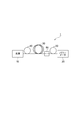
- FIG. 1 is a diagram showing an example of a device configuration for measuring crosstalk between cores of a multicore optical fiber and receiving light output from the multicore optical fiber at the time of measurement.
- the measurement light is incident only on a specific core of the multi-core optical fiber to be measured, and the emitted light from a specific core such as that core or another core is measured.
- the inter-core crosstalk measuring apparatus 1 is a single mode in which the light source 10 and one end are optically connected to one of the cores at the incident end of the multicore optical fiber 30 to be measured.
- the single mode optical fiber 50 (light receiving optical fiber as a light receiving waveguide), the output end of the multi-core optical fiber 30 and the single mode optical fiber 50.
- the optical component 60 and the power meter 20 are provided. That is, in the measurement apparatus 1, as an example, the multicore optical fiber 30 that is a measurement target is disposed between the light source 10 and the power meter 20. A single mode optical fiber 40 is disposed on the incident end side of the multi-core optical fiber 30, and a single mode optical fiber 50 is disposed on the exit end side.
- the multi-core optical fiber 30 and the single mode optical fiber 50 are connected by an optical component 60 that connects the cores. Further, an optical waveguide or the like may be used in place of the single mode optical fibers 40 and 50.
- a single-core optical fiber or optical waveguide disposed downstream (output end side) of the multi-core optical fiber 30 for guiding light output from the multi-core optical fiber 30 to be measured is In the embodiment, it is called a light receiving waveguide.
- the single mode optical fibers 40 and 50 are made of a glass material whose surface is covered with a coating.
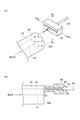
- FIG. 2A illustrates a configuration that realizes non-contact optical coupling.
- FIG. 2B shows a configuration in which the cores of the multi-core optical fiber 30 and the single mode optical fiber 40 are fixed using an adhesive. Note that the measurement light is introduced into the first core 31 of the multi-core optical fiber 30 to be measured.
- the single mode optical fiber 50 is optically coupled to the second core 32 different from the first core 31 at the emission end face 30a in order to measure the inter-core crosstalk in the multi-core optical fiber 30 (the first mode 31).
- the light output from the second core 32 is guided through the single mode optical fiber 50).
- the end of the single mode optical fiber 50 is installed in a holder 61 composed of a lower member and an upper member in which a V-groove is formed.
- the holder 61 moves in the horizontal direction indicated by arrows S 1a and S 1b in the drawing, and also moves in the vertical direction indicated by arrows S 2a and S 2b in the drawing.
- the holder 61 on which the end portion of the single mode optical fiber 50 is installed moves the core of the single mode optical fiber 50 relative to the second core 32 of the multicore optical fiber 30, thereby allowing the multicore optical fiber 30 to move. Alignment of the second core 32 and the core of the single mode optical fiber 50 is performed. In the example of FIG.
- the multicore optical fiber 30 and the single mode optical fiber 50 are held without being bonded using an adhesive.
- the end portion of the single-mode optical fiber 50 including the end face facing the second core 32 of the multi-core optical fiber 30 is exposed to the glass part from which the coating has been removed (the glass part is covered with the coating). Also good).
- a ferrule is not mounted at the end of the single mode optical fiber 50. With this configuration, the light output from the second core 32 of the multi-core optical fiber 30 enters the core of the single mode optical fiber 50 in which no ferrule is mounted at the end.
- the multi-core optical fiber 30 and the single-mode optical fiber 50 are bonded. Bonding is performed using an agent 63. Subsequently, the transparent ferrule 62 is bonded to the end portion of the single mode optical fiber 50 including the end surface facing the second core 32 of the multi-core optical fiber 30 with the glass portion from which the coating has been removed exposed. 64 (the ferrule 62 moves along the end of the single mode optical fiber 50 along the arrow S3). Note that the refractive index of the adhesive for mounting the ferrule is higher than the refractive index of the cladding portion of the single mode optical fiber 50. With this configuration, the light output from the second core 32 of the multi-core optical fiber 30 enters the core of the single mode optical fiber 50 in which the transparent ferrule is mounted at the end.
- E is an electric field vector
- H is a magnetic field vector
- p is a subscript (subscript)
- the parameter on the output side of the butt coupling is q.
- Parameters attached as subscripts) are components on the incident side
- U z is a unit vector in the light propagation direction.
- a single core optical fiber (single mode optical fiber: SMF) is studied for the purpose of investigating the crosstalk at the coupling portion between the multicore optical fiber and the light receiving waveguide where the crosstalk between cores during light propagation is very small and can be ignored.
- SMF single mode optical fiber
- the relationship between the amount of axial misalignment of the core and the coupling power (coupling power profile) at the coupling portion when they were coupled to each other was examined using an actual single mode optical fiber.
- the coupling power is standardized so that it becomes 0 dB when there is no axial deviation.
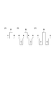
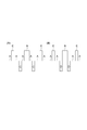
- FIG. 3 shows an example of the refractive index profile of a single mode optical fiber.
- 3A shows a matched clad type having only a clad layer A and a core layer B having a higher refractive index than that of the clad layer A.
- FIG. 3B shows a trench layer C having a low refractive index inside the clad layer A.
- FIG. 3C shows a depressed type refractive index profile having a depressed layer D between the cladding layer A and the core layer B.
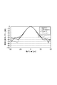
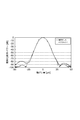
- FIG. FIG. 4 shows a coupling loss profile between matched-clad single-mode optical fibers
- FIG. 5 shows a coupling loss profile between trench-type single-mode optical fibers.
- square glass represents a rod-shaped glass ferrule having a square cross section
- cylindrical glass with metal represents a glass ferrule with a metal housing attached to its surface
- zirconia represents a ferrule made of zirconia.
- Bored fiber represents a state in which the coating at the end of the single mode optical fiber 50 is removed and the glass portion is exposed.
- FIG. 6 shows an average value of the coupling power in the range where the absolute value of the axis deviation amount of FIGS.
- the average value of the coupling power is higher in the order of the matched clad single-mode optical fiber and the trench single-mode optical fiber.
- the average value of the coupling power is higher in the order of the zirconia ferrule, the glass ferrule (regardless of the shape and the presence or absence of the metal part), and the bare fiber.
- the average value of the coupling power was significantly reduced when trench-type single-mode optical fibers were butt-coupled with each other, especially when compared with matched-clad single-mode optical fibers. Is done.
- the trench type single mode optical fiber has a trench layer having a low refractive index around the core, the coupling from the clad mode to the core mode is suppressed by the trench layer as a barrier.
- the refractive index distribution shape desirable as a light receiving waveguide used in a measurement system for measuring inter-core crosstalk in a multicore optical fiber to be measured has the following characteristics: It turns out that.
- a portion having a lower refractive index than the clad exists between the core and the clad, such as a trench type refractive index distribution and a depressed type refractive index distribution.
- the trench layer and the depressed layer have a thickness and a refractive index difference with respect to the clad that sufficiently inhibit the coupling from the clad mode to the core mode.
- the radius from the core center to the interface between the trench layer and the cladding layer (trench outer diameter) or the radius from the depressed layer to the interface between the cladding layer (depressed layer) should be as small as possible. .
- the reason for this is that when measuring inter-core crosstalk in a multi-core optical fiber, when the output light from the coupling-target core is received by the light-receiving waveguide, the coupling source at the butt surface of the multi-core optical fiber and the light-receiving waveguide This is because most of the power of the output light from the core is coupled to the outside of the cladding outer diameter and the depressed outer diameter of the light receiving waveguide. This is intended to prevent the component that should inhibit the coupling of the light receiving waveguide to the core from coupling inside the blocking barrier.
- a butt end portion with the multi-core optical fiber 30 has the following characteristics.
- the coating is removed and the glass portion is exposed.
- the refractive index of the coating is higher than that of the cladding, and the end face of the light receiving optical fiber can be cut cleanly without leaving the coating, the glass portion may be covered with the coating.
- the bonding surface between the light receiving optical fiber and the ferrule requires a certain area, so the light receiving optical fiber is bonded to the ferrule.
- the state is preferable.
- the ferrule is made of a material that transmits light in a wavelength band used for measurement without scattering, so that the light scattered by the ferrule does not return to the light receiving optical fiber.
- the ferrule and the adhesive that bonds the ferrule and the fiber have a higher refractive index than the clad of the optical fiber for light reception so that the clad mode power can easily escape to the ferrule.
- FIG. 7A shows a trench type refractive index distribution having a trap layer E, and FIG.
- FIG. 7B shows a depressed type refractive index distribution having a trap layer E.
- the clad layer A is provided on the outer periphery of the core layer B, and the trench layer C and the trap layer E are provided in the clad layer A in the order from the core B. ing.
- a depressed layer D is provided between the core layer B and the clad layer A, and is within the clad layer A and from the core layer B more than the depressed layer D.
- a trap layer E is provided at a far position.
- the core is refracted more than the cladding around the core, such as a depressed type refractive index distribution or a trench type refractive index distribution.
- the layer having a low refractive index suppresses propagation of noise and the like from the clad side to the core.
- the inter-core crosstalk can be accurately measured.
- the light receiving waveguide described above may have a plurality of cores, and can receive light output from the multicore optical fiber according to the present embodiment. Even when the method is used when signal light is simultaneously and individually extracted from a plurality of cores of a multicore fiber, crosstalk between cores can be suppressed and signal light with less noise can be extracted. This enables measurement methods (such as measurement of transmission loss, cut-off wavelength, etc.) in which the influence of crosstalk other than crosstalk measurement is a concern, and reception of signal light at a receiver for multicore optical fibers in a transmission system. It can also be applied to.
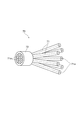
- FIG. 8 shows a specific configuration of the light receiving waveguide having a plurality of cores.
- the light receiving waveguide 70 shown in FIG. 8 includes a plurality of single-core optical fibers 71 each having a core 71a and satisfying the characteristics of the present invention, and a plurality of single-core waveguides at one end thereof.
- Core optical fibers 71 are bundled. This one end is ferruled or connected in a state where the single-core optical fibers 71 are arranged so as to match the core arrangement of the multicore optical fiber 30 (in FIG. 8, one end is fixed by the ferrule 72). Example).
- the single-core optical fibers are separated one by one.
- the light receiving waveguide 70 shown in FIG. 8 is bundled with a plurality of single-core optical fibers 71 being maintained in a predetermined arrangement at one end, while a plurality of single core optical fibers 71 are bundled at the other end.
- This is a fan-out device in which single-core optical fibers 71 are separated from each other.
- Such a light receiving waveguide 70 can also be used as a light receiving waveguide for guiding the light output from each of the cores on the emission end face 30a of the multi-core optical fiber 30.
Landscapes
- Physics & Mathematics (AREA)
- General Physics & Mathematics (AREA)
- Optics & Photonics (AREA)
- Chemical & Material Sciences (AREA)
- Analytical Chemistry (AREA)
- Optical Couplings Of Light Guides (AREA)
- Optical Integrated Circuits (AREA)
- Photometry And Measurement Of Optical Pulse Characteristics (AREA)
Abstract
In the present invention a light reception waveguide that has been provided, in a manner similar to a depressed type or a trench type, with a layer having a lower refractive index than the cladding on the periphery of the core is used in a light receiving means that receives light output from multi-core optical fiber, and this low refractive index layer can thereby suppress the propagation of noise and the like from the cladding side to the core. As a result, even when the crosstalk between cores is small, components differing from components that originated in the crosstalk are reduced, enabling accurate measurement of the crosstalk between cores.
Description
本発明は、マルチコア光ファイバから出力される光の受光方法、及び、マルチコア光ファイバから出力される光を分離するための分離装置に関する。
The present invention relates to a method for receiving light output from a multi-core optical fiber and a separation device for separating light output from the multi-core optical fiber.
近年、複数のコアを有するマルチコア光ファイバが盛んに研究されている。マルチコア光ファイバは、例えば、その長手方向に垂直な断面において複数のコアが二次元状に分散配置された構成を有し、複数のコア間でクロストークが発生することが知られている。このマルチコア光ファイバにおけるコア間クロストークの測定方法と、測定時のマルチコア光ファイバから出力される光の受光方法が、例えば非特許文献1~3等に開示されている。具体的には、クロストークの測定は、結合元コアから結合先コアへの光パワーの移行率の測定として行われる。
In recent years, multicore optical fibers having a plurality of cores have been actively studied. For example, it is known that a multi-core optical fiber has a configuration in which a plurality of cores are two-dimensionally distributed in a cross section perpendicular to the longitudinal direction, and crosstalk occurs between the plurality of cores. For example, Non-Patent Documents 1 to 3 disclose a method for measuring crosstalk between cores in this multicore optical fiber and a method for receiving light output from the multicore optical fiber during measurement. Specifically, the measurement of crosstalk is performed as a measurement of the transfer rate of optical power from the coupling source core to the coupling destination core.
発明者らは、上述の従来技術について検討した結果、以下のような課題を発見した。すなわち、入射光伝搬に起因したコア間クロストークが極めて低いマルチコア光ファイバにおいてそのクロストークを測ろうとすると、ノイズ光や、受光用光ファイバとの結合時のクロストークの方が大きく、正確な測定ができない場合がある。具体的には、マルチコア光ファイバの出射端で、結合先コアと出射側の受光用光ファイバのコアとを調芯すると、結合先コアからの出力光より遙かに大きな結合元コアからの出力光が、受光用光ファイバのクラッドに入射する。ここで、ファイバ端部の状態や、ファイバ構造によっては、受光用光ファイバのクラッドに入射した光が受光用光ファイバのコアに結合してしまい、測定時のノイズになってしまう。
The inventors have found the following problems as a result of examining the above-described conventional technology. In other words, when trying to measure the crosstalk in a multi-core optical fiber that has extremely low crosstalk between cores due to the propagation of incident light, the crosstalk at the time of coupling with noise light or the optical fiber for receiving light is larger, and the measurement is accurate. May not be possible. Specifically, if the coupling destination core and the core of the receiving optical fiber on the emission side are aligned at the output end of the multicore optical fiber, the output from the coupling source core is much larger than the output light from the coupling destination core. Light enters the cladding of the light receiving optical fiber. Here, depending on the state of the fiber end and the fiber structure, the light incident on the cladding of the light receiving optical fiber is coupled to the core of the light receiving optical fiber, resulting in noise during measurement.
本発明は上記を鑑みてなされたものであり、コア間クロストークが小さい場合であっても精度よく該コア間クロストークの測定を可能にするマルチコア光ファイバから出力される光の受光方法、及び、分離装置を提供することを目的とする。
The present invention has been made in view of the above, and a method of receiving light output from a multicore optical fiber that enables accurate measurement of crosstalk between cores even when the crosstalk between cores is small, and An object is to provide a separation device.
上記目的を達成するため、本発明に係るマルチコア光ファイバから出力される光の受光方法は、第1態様として、マルチコア光ファイバの出射端側に特徴的な構造を有する受光用導波路を配置し、マルチコア光ファイバの第1の端面において第1のコアに測定光を入射し、マルチコア光ファイバの第1の端面に対向する第2の端面において第1のコアと異なる第2のコアから出射される光に受光用導波路内を導波させ、そして、受光用導波路を導波した光を受光する。ここで、受光用導波路は、マルチコア光ファイバから出力される光が到達する位置に配置され、マルチコア光ファイバのコアから出力される光を導波する導波路であって、コア周囲をクラッドよりも屈折率が低い層で囲まれたディプレスト型あるいはトレンチ型の屈折率構造を持つ。
In order to achieve the above object, a light receiving method for light output from a multicore optical fiber according to the present invention includes, as a first aspect, a light receiving waveguide having a characteristic structure on the emission end side of the multicore optical fiber. The measurement light is incident on the first core at the first end face of the multi-core optical fiber, and is emitted from the second core different from the first core at the second end face opposite to the first end face of the multi-core optical fiber. Light is guided through the light receiving waveguide, and the light guided through the light receiving waveguide is received. Here, the light receiving waveguide is a waveguide that guides the light output from the core of the multi-core optical fiber, and is disposed at a position where the light output from the multi-core optical fiber reaches. Also, it has a depressed type or trench type refractive index structure surrounded by a layer having a low refractive index.
なお、ディプレスト層およびトレンチ層の少なくともいずれかは、全てが固体で構成されている必要はなく、空孔により、平均的な屈折率がクラッドより低くなっている構造でも良い。
It should be noted that at least one of the depressed layer and the trench layer does not have to be composed entirely of solid, and may have a structure in which the average refractive index is lower than that of the cladding due to the holes.
上記第1態様の受光方法によれば、ディプレスト型あるいはトレンチ型のように、コア周囲にクラッドよりも屈折率が低い層が設けられた受光用導波路を用いることで、この屈折率の低い層がクラッド側からコアへのノイズ等の伝搬を抑制することができる。その結果、コア間クロストークが小さいマルチコア光ファイバに対する測定であってもクロストーク由来とは異なる成分が低減されてコア間クロストークを精度よく測定することが可能になる。
According to the light receiving method of the first aspect, the refractive index is low by using a light receiving waveguide in which a layer having a refractive index lower than that of the cladding is provided around the core, such as a depressed type or a trench type. The layer can suppress propagation of noise and the like from the clad side to the core. As a result, even when measurement is performed on a multi-core optical fiber having a small inter-core crosstalk, components different from those derived from crosstalk are reduced, and the inter-core crosstalk can be accurately measured.
ここで、上記作用を効果的に奏する構成としては、以下の態様(第1態様に適用可能な第2態様)が挙げられる。具体的に受光用導波路は、その表面が被覆によって覆われた、ガラス材料からなる受光用光ファイバを含む。マルチコア光ファイバの第2のコアと受光用光ファイバのコアとが調芯された後、マルチコア光ファイバと受光用光ファイバとは、接着剤を用いて接着されることなく保持される。マルチコア光ファイバの第2のコアに対面する端面を含む受光用光ファイバの端部は、被覆が除去されたガラス部が露出しているか、あるいは、ガラス部が被覆によって覆われている。以上の第2態様において、マルチコア光ファイバの第2のコアから出力された光は、受光用光ファイバの端部にフェルールが実装されていない状態で受光用光ファイバのコアへ入射する。
Here, examples of the configuration that effectively exhibits the above-described operation include the following modes (second mode applicable to the first mode). Specifically, the light receiving waveguide includes a light receiving optical fiber made of a glass material whose surface is covered with a coating. After the second core of the multi-core optical fiber and the core of the light-receiving optical fiber are aligned, the multi-core optical fiber and the light-receiving optical fiber are held without being bonded using an adhesive. At the end of the light receiving optical fiber including the end face facing the second core of the multi-core optical fiber, the glass part from which the coating has been removed is exposed, or the glass part is covered with the coating. In the second aspect described above, the light output from the second core of the multi-core optical fiber enters the core of the light receiving optical fiber in a state where no ferrule is mounted on the end of the light receiving optical fiber.
上記作用を効果的に奏する他の構成としては、以下の態様(上記第1態様に適用可能な第3態様)が挙げられる。具体的に受光用導波路は、その表面が被覆で覆われた、ガラス材料からなる受光用光ファイバを含む。マルチコア光ファイバの第2のコアと受光用光ファイバのコアとが調芯された後、マルチコア光ファイバと受光用光ファイバとは接着剤を用いて接着される。マルチコア光ファイバの第2のコアに対面する端面を含む受光用光ファイバの端部には、被覆が除去されたガラス部が露出した状態で、透明なフェルールが接着剤で実装される。なお、フェルール実装用の接着剤の屈折率は、前記受光用光ファイバのクラッド部の屈折率よりも高い。以上の第3態様において、マルチコア光ファイバの第2のコアから出力された光は、受光用光ファイバの端部に透明なフェルールが実装された状態で受光用光ファイバのコアへ入射する。
Other configurations that effectively exhibit the above-described action include the following aspects (third aspect applicable to the first aspect). Specifically, the light receiving waveguide includes a light receiving optical fiber made of a glass material whose surface is covered with a coating. After the second core of the multi-core optical fiber and the core of the light-receiving optical fiber are aligned, the multi-core optical fiber and the light-receiving optical fiber are bonded using an adhesive. A transparent ferrule is mounted with an adhesive on the end portion of the light receiving optical fiber including the end face facing the second core of the multi-core optical fiber with the glass portion from which the coating has been removed exposed. Note that the refractive index of the adhesive for mounting the ferrule is higher than the refractive index of the cladding portion of the light receiving optical fiber. In the above third aspect, the light output from the second core of the multi-core optical fiber is incident on the core of the light receiving optical fiber in a state where a transparent ferrule is mounted on the end of the light receiving optical fiber.
また、本発明に係るマルチコア光ファイバから出力される光の受光方法は、第4態様として、マルチコア光ファイバの出射端側に特徴的な構造を有する受光用導波路を配置し、マルチコア光ファイバの第1の端面において1又はそれ以上のコアそれぞれに測定光、あるいは信号光を入射し、マルチコア光ファイバの第1の端面と対向する第2の端面においてコアそれぞれから出力される光に受光用導波路内を導波させることで、第2の端面におけるコアそれぞれから出力される光を分離し、そして、受光用導波路の複数のコアを導波した光を個別に受光しても良い。
The light receiving method of the light output from the multi-core optical fiber according to the present invention, as a fourth aspect, arranges a light receiving waveguide having a characteristic structure on the emission end side of the multi-core optical fiber, and Measurement light or signal light is incident on each of the one or more cores at the first end face, and the light output from each of the cores at the second end face opposite to the first end face of the multicore optical fiber is guided to receive light. By guiding the light in the waveguide, the light output from each of the cores on the second end face may be separated, and the light guided through the plurality of cores of the light receiving waveguide may be individually received.
この第4態様において、受光用導波路は、マルチコア光ファイバから出力される光が到達する位置に配置され、マルチコア光ファイバのコアから出力される光を導波する導波路であって、複数のコアを有し、各コア周囲をクラッドよりも屈折率が低い層で囲まれたディプレスト型あるいはトレンチ型の屈折率構造を持つ。また、ディプレスト層およびトレンチ層の少なくともいずれかは、クラッドよりも屈折率が低い固体のみによって形成され、あるいは、固体内に空孔を有することにより平均的な屈折率がクラッドより低い層として形成される。
In this fourth aspect, the light receiving waveguide is a waveguide that is disposed at a position where the light output from the multi-core optical fiber reaches and guides the light output from the core of the multi-core optical fiber. Each of the cores has a depressed or trench type refractive index structure surrounded by a layer having a lower refractive index than the cladding. In addition, at least one of the depressed layer and the trench layer is formed only of a solid having a lower refractive index than that of the clad, or is formed as a layer having an average refractive index lower than that of the clad by having pores in the solid. Is done.
第4態様に適用可能な第5態様として、受光用導波路は、ディプレスト層あるいはトレンチ層より外側に、クラッドよりも屈折率の高いトラップ層を有する屈折率構造を有しても良い。
As a fifth aspect applicable to the fourth aspect, the light receiving waveguide may have a refractive index structure having a trap layer having a refractive index higher than that of the cladding outside the depressed layer or the trench layer.
また、第5態様として、本発明に係るマルチコア光ファイバから出力される光の分離装置は、マルチコア光ファイバのコアから出射された光を導波する受光用導波路であって、特徴的な構造を有するとともにマルチコア光ファイバから出力された光が到達する位置に配置された受光用導波路を備える。受光用導波路は、複数のコアを有し、各コア周囲をクラッドよりも屈折率が低い層で囲まれたディプレスト型あるいはトレンチ型の屈折率構造を持つ。また、ディプレスト層およびトレンチ層の少なくともいずれかは、クラッドよりも屈折率が低い固体のみによって形成され、あるいは、固体内に空孔を有することにより平均的な屈折率がクラッドより低い層として形成されても良い。
Further, as a fifth aspect, the separation device for light output from the multicore optical fiber according to the present invention is a light receiving waveguide for guiding light emitted from the core of the multicore optical fiber, and has a characteristic structure And a light receiving waveguide disposed at a position where the light output from the multi-core optical fiber reaches. The light receiving waveguide has a plurality of cores, and has a depressed type or trench type refractive index structure in which each core is surrounded by a layer having a refractive index lower than that of the cladding. In addition, at least one of the depressed layer and the trench layer is formed only of a solid having a lower refractive index than that of the clad, or is formed as a layer having an average refractive index lower than that of the clad by having pores in the solid. May be.
この第5態様において、マルチコア光ファイバの第1の端面において1又はそれ以上のコアそれぞれに測定光、あるいは信号光が入射される。マルチコア光ファイバの第1の端面に対向する第2の端面においてコアそれぞれから出力される光に受光用導波路内を導波させることで、第2の端面におけるコアそれぞれから出力される光が分離される。その結果、受光用導波路の複数のコアを導波した光が個別に受光される。
In this fifth aspect, measurement light or signal light is incident on each of one or more cores on the first end face of the multi-core optical fiber. The light output from each of the cores at the second end face is separated by guiding the light output from each of the cores at the second end face facing the first end face of the multi-core optical fiber through the light receiving waveguide. Is done. As a result, the light guided through the plurality of cores of the light receiving waveguide is individually received.
上記第5態様の作用を効果的に奏する構成としては、以下の態様(第5態様に適用可能な第6態様)が挙げられる。具体的には、受光用導波路は、一端が束ねられた複数本の単芯コア光ファイバにより構成される。この受光用導波路の一端は、複数本の単芯コア光ファイバがマルチコアファイバのコア配置に合わせて配列された状態でフェルール化、あるいは、コネクタ化される。一方、受光用導波路の他端は、複数本の単芯コア光ファイバが個別に分離可能な状態になっている。
The following aspect (sixth aspect applicable to the fifth aspect) can be cited as a configuration that effectively exhibits the action of the fifth aspect. Specifically, the light receiving waveguide is constituted by a plurality of single-core optical fibers whose one ends are bundled. One end of the light receiving waveguide is formed into a ferrule or a connector in a state in which a plurality of single core optical fibers are arranged in accordance with the core arrangement of the multicore fiber. On the other hand, the other end of the light receiving waveguide is in a state in which a plurality of single-core optical fibers can be individually separated.
本発明によれば、コア間クロストークが小さいマルチコア光ファイバに対する測定であっても精度よくコア間クロストークの測定を可能にするマルチコア光ファイバから出力される光の受光方法等の提供が可能になる。
According to the present invention, it is possible to provide a method for receiving light output from a multi-core optical fiber that enables accurate measurement of cross-core cross-talk even when measuring a multi-core optical fiber with low cross-core between cores. Become.
以下、添付図面を参照して、本発明を実施するための最良の形態を詳細に説明する。なお、図面の説明においては同一要素には同一符号を付し、重複する説明を省略する。
The best mode for carrying out the present invention will be described below in detail with reference to the accompanying drawings. In the description of the drawings, the same elements are denoted by the same reference numerals, and redundant description is omitted.
図1は、マルチコア光ファイバのコア間クロストークを測定し、また、測定時のマルチコア光ファイバから出力される光の受光する際の装置構成の一例を示す図である。マルチコア光ファイバのコア間クロストークを測定するとき、測定対象のマルチコア光ファイバの特定のコアのみに測定光を入射させ、そのコアや別のコアなどのある特定のコアからの出射光を測定する必要がある。よって、図1に示されたように、コア間クロストーク測定装置1は、光源10、一端が測定対象であるマルチコア光ファイバ30の入射端におけるいずれかのコアと光学的に接続されたシングルモード光ファイバ40(送光用光ファイバ)、シングルモード光ファイバ50(受光用導波路としての受光用光ファイバ)、マルチコア光ファイバ30の出射端とシングルモード光ファイバ50とを光学的に結合させるための光学部品60と、パワーメータ20を備える。すなわち、当該測定装置1においては、一例として、光源10とパワーメータ20との間に、測定対象であるマルチコア光ファイバ30が配置される。マルチコア光ファイバ30の入射端側にはシングルモード光ファイバ40、出射端側にはシングルモード光ファイバ50がそれぞれ配置される。マルチコア光ファイバ30とシングルモード光ファイバ50との間は、コア同士を接続する光学部品60で接続される。また、シングルモード光ファイバ40、50に替えて、光導波路等が用いられることもある。
FIG. 1 is a diagram showing an example of a device configuration for measuring crosstalk between cores of a multicore optical fiber and receiving light output from the multicore optical fiber at the time of measurement. When measuring crosstalk between cores of a multi-core optical fiber, the measurement light is incident only on a specific core of the multi-core optical fiber to be measured, and the emitted light from a specific core such as that core or another core is measured. There is a need. Therefore, as shown in FIG. 1, the inter-core crosstalk measuring apparatus 1 is a single mode in which the light source 10 and one end are optically connected to one of the cores at the incident end of the multicore optical fiber 30 to be measured. In order to optically couple the optical fiber 40 (light transmitting optical fiber), the single mode optical fiber 50 (light receiving optical fiber as a light receiving waveguide), the output end of the multi-core optical fiber 30 and the single mode optical fiber 50. The optical component 60 and the power meter 20 are provided. That is, in the measurement apparatus 1, as an example, the multicore optical fiber 30 that is a measurement target is disposed between the light source 10 and the power meter 20. A single mode optical fiber 40 is disposed on the incident end side of the multi-core optical fiber 30, and a single mode optical fiber 50 is disposed on the exit end side. The multi-core optical fiber 30 and the single mode optical fiber 50 are connected by an optical component 60 that connects the cores. Further, an optical waveguide or the like may be used in place of the single mode optical fibers 40 and 50.
ここで、測定対象であるマルチコア光ファイバ30から出力される光を導波させるための、該マルチコア光ファイバ30より後段(出力端側)に配置されるシングルコアの光ファイバや光導波路を、本実施形態では受光用導波路と呼ぶ。また、シングルモード光ファイバ40、50は、その表面が被覆で覆われた、ガラス材料からなる。
Here, a single-core optical fiber or optical waveguide disposed downstream (output end side) of the multi-core optical fiber 30 for guiding light output from the multi-core optical fiber 30 to be measured is In the embodiment, it is called a light receiving waveguide. The single mode optical fibers 40 and 50 are made of a glass material whose surface is covered with a coating.
マルチコア光ファイバ30とシングルモード光ファイバ40のコア同士の結合は、例えば図2に示された構成により実現可能である。図2(A)には一例として、非接触による光結合を実現する構成が示されている。また、図2(B)に示された例では、マルチコア光ファイバ30とシングルモード光ファイバ40のコア同士が接着剤を用いて固定される構成が示されている。なお、測定光は、測定対象であるマルチコア光ファイバ30の第1のコア31に導入される。シングルモード光ファイバ50は、当該マルチコア光ファイバ30におけるコア間クロストークを測定するため、出射端面30aにおいて第1のコア31とは異なる第2のコア32に対して光学的に結合される(第2のコア32から出力される光がシングルモード光ファイバ50を導波する)。
The coupling between the cores of the multi-core optical fiber 30 and the single mode optical fiber 40 can be realized, for example, by the configuration shown in FIG. As an example, FIG. 2A illustrates a configuration that realizes non-contact optical coupling. 2B shows a configuration in which the cores of the multi-core optical fiber 30 and the single mode optical fiber 40 are fixed using an adhesive. Note that the measurement light is introduced into the first core 31 of the multi-core optical fiber 30 to be measured. The single mode optical fiber 50 is optically coupled to the second core 32 different from the first core 31 at the emission end face 30a in order to measure the inter-core crosstalk in the multi-core optical fiber 30 (the first mode 31). The light output from the second core 32 is guided through the single mode optical fiber 50).
図2(A)において、シングルモード光ファイバ50の端部は、V溝が形成された下側部材と上側部材で構成された保持具61に設置されている。この保持具61は、図中の矢印S1a、S1bで示された水平方向に移動することにより、また、図中の矢印S2a、S2bで示された垂直方向に移動する。シングルモード光ファイバ50の端部が設置された保持具61が、マルチコア光ファイバ30における第2のコア32に対し、シングルモード光ファイバ50のコアを相対的に移動させることで、マルチコア光ファイバ30における第2のコア32とシングルモード光ファイバ50のコアとの調芯が行われる。なお、この図2(A)の例では、調芯後、マルチコア光ファイバ30とシングルモード光ファイバ50とは、接着剤を用いて接着されることなく保持される。また、マルチコア光ファイバ30の第2のコア32に対面する端面を含むシングルモード光ファイバ50の端部は、被覆が除去されたガラス部が露出している(ガラス部は被覆によって覆われていてもよい)。シングルモード光ファイバ50の端部には、フェルールは実装されていない。この構成により、マルチコア光ファイバ30の第2のコア32から出力された光は、端部にフェルールが実装されていないシングルモード光ファイバ50のコアへ入射する。
In FIG. 2A, the end of the single mode optical fiber 50 is installed in a holder 61 composed of a lower member and an upper member in which a V-groove is formed. The holder 61 moves in the horizontal direction indicated by arrows S 1a and S 1b in the drawing, and also moves in the vertical direction indicated by arrows S 2a and S 2b in the drawing. The holder 61 on which the end portion of the single mode optical fiber 50 is installed moves the core of the single mode optical fiber 50 relative to the second core 32 of the multicore optical fiber 30, thereby allowing the multicore optical fiber 30 to move. Alignment of the second core 32 and the core of the single mode optical fiber 50 is performed. In the example of FIG. 2A, after the alignment, the multicore optical fiber 30 and the single mode optical fiber 50 are held without being bonded using an adhesive. In addition, the end portion of the single-mode optical fiber 50 including the end face facing the second core 32 of the multi-core optical fiber 30 is exposed to the glass part from which the coating has been removed (the glass part is covered with the coating). Also good). A ferrule is not mounted at the end of the single mode optical fiber 50. With this configuration, the light output from the second core 32 of the multi-core optical fiber 30 enters the core of the single mode optical fiber 50 in which no ferrule is mounted at the end.
一方、図2(B)では、マルチコア光ファイバ30の第2のコア32とシングルモード光ファイバ光ファイバ50のコアとが調芯された後、マルチコア光ファイバ30とシングルモード光ファイバ50とが接着剤63を用いて接着される。続いて、マルチコア光ファイバ30の第2のコア32に対面する端面を含むシングルモード光ファイバ50の端部には、被覆が除去されたガラス部が露出した状態で、透明なフェルール62が接着剤64で実装される(フェルール62は、矢印S3に沿ってシングルモード光ファイバ50の端部に沿って移動)。なお、フェルール実装用の接着剤の屈折率は、シングルモード光ファイバ50のクラッド部の屈折率よりも高い。この構成により、マルチコア光ファイバ30の第2のコア32から出力された光は、透明フェルールが端部に実装されたシングルモード光ファイバ50のコアへ入射する。
On the other hand, in FIG. 2B, after the second core 32 of the multi-core optical fiber 30 and the core of the single-mode optical fiber 50 are aligned, the multi-core optical fiber 30 and the single-mode optical fiber 50 are bonded. Bonding is performed using an agent 63. Subsequently, the transparent ferrule 62 is bonded to the end portion of the single mode optical fiber 50 including the end surface facing the second core 32 of the multi-core optical fiber 30 with the glass portion from which the coating has been removed exposed. 64 (the ferrule 62 moves along the end of the single mode optical fiber 50 along the arrow S3). Note that the refractive index of the adhesive for mounting the ferrule is higher than the refractive index of the cladding portion of the single mode optical fiber 50. With this configuration, the light output from the second core 32 of the multi-core optical fiber 30 enters the core of the single mode optical fiber 50 in which the transparent ferrule is mounted at the end.
受光用導波路をマルチコア光ファイバ30の後段に配置し、マルチコア光ファイバ30から出力された測定光に受光用導波路内を導波させることで、測定光の伝搬中に生じるコア間クロストークが極めて低いマルチコア光ファイバにおけるコア間クロストークの測定を考える。このような条件下においては、理論値から予測される光伝搬によるコア間クロストークよりも大きなクロストークが測定されることが確認された。そして、この値について、従来の突き合わせ結合の結合効率の式(岡本勝就、光導波路の基礎、コロナ社)である以下の数式(1)から予測されるマルチコア光ファイバと受光用導波路の結合部におけるコア間クロストークを考慮に入れても説明できないことを発明者は発見した。

By arranging the light receiving waveguide in the subsequent stage of the multi-core optical fiber 30 and guiding the measurement light output from the multi-core optical fiber 30 in the light receiving waveguide, crosstalk between cores generated during propagation of the measuring light is reduced. Consider the measurement of crosstalk between cores in a very low multicore optical fiber. Under such conditions, it was confirmed that crosstalk larger than inter-core crosstalk due to light propagation predicted from theoretical values was measured. Then, with respect to this value, the coupling between the multicore optical fiber and the light receiving waveguide predicted from the following formula (1), which is a formula for coupling efficiency of conventional butt coupling (Katsuaki Okamoto, fundamentals of optical waveguide, Corona) The inventor has found that this cannot be explained even if the crosstalk between the cores is taken into account.
なお、上記数式(1)において、Eは電界のベクトル、Hは磁界のベクトル、pが添え字(下付き文字)として付いているパラメータは突き合わせ結合の出力側の成分で、qが添え字(下付き文字)として付いているパラメータは入射側の成分であり、Uzは光の伝搬方向の単位ベクトルである。
In the above formula (1), E is an electric field vector, H is a magnetic field vector, p is a subscript (subscript), and the parameter on the output side of the butt coupling is q. Parameters attached as subscripts) are components on the incident side, and U z is a unit vector in the light propagation direction.
上記式(1)をスカラー表示の電界で簡単に書き直すと、以下の数式(2)となり、光強度の結合係数としては以下の数式(3)と表すことができる。
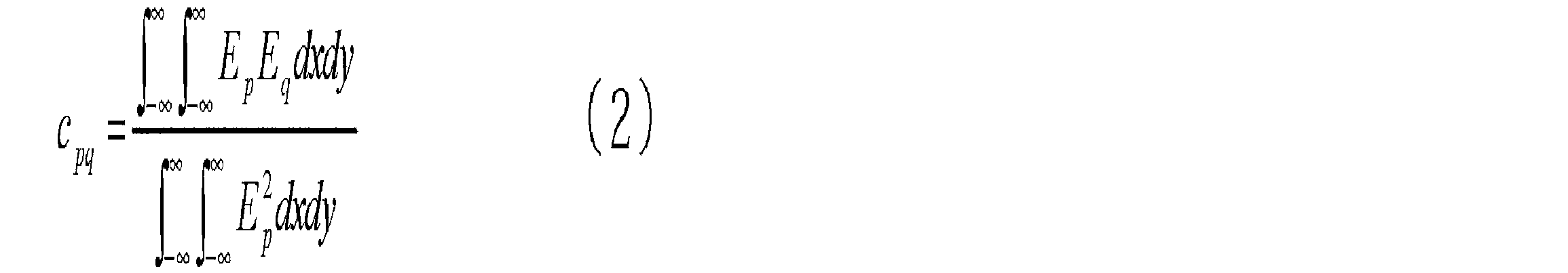
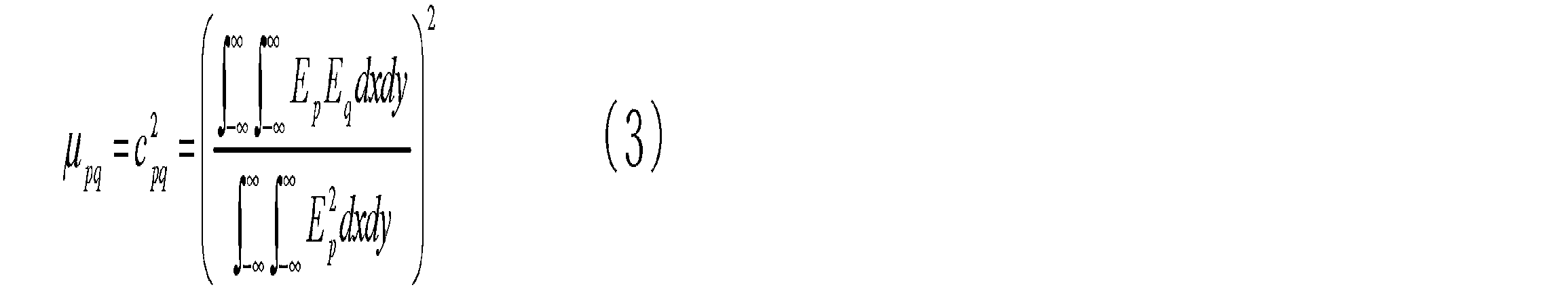
When the above equation (1) is simply rewritten with an electric field of scalar display, the following equation (2) is obtained, and the coupling coefficient of light intensity can be represented by the following equation (3).
通常、シングルモード光ファイバでは、基底モードの電界分布は、コアの中心から離れるにつれて単調減少である。
Normally, in a single mode optical fiber, the electric field distribution in the fundamental mode decreases monotonically as the distance from the center of the core increases.
ここで、光伝搬中のコア間クロストークが非常に小さく無視できるマルチコア光ファイバと受光用導波路の結合部におけるクロストークについて調べることを目的とし、単芯コア光ファイバ(シングルモード光ファイバ:SMF)同士を結合させた場合の結合部における、コアの軸ズレ量と結合パワーとの関係(結合パワープロファイル)を、実際のシングルモード光ファイバを用いて調べた。結合パワーについては、軸ズレ量無しのときが0dBになる様に規格化してある。
Here, a single core optical fiber (single mode optical fiber: SMF) is studied for the purpose of investigating the crosstalk at the coupling portion between the multicore optical fiber and the light receiving waveguide where the crosstalk between cores during light propagation is very small and can be ignored. ) The relationship between the amount of axial misalignment of the core and the coupling power (coupling power profile) at the coupling portion when they were coupled to each other was examined using an actual single mode optical fiber. The coupling power is standardized so that it becomes 0 dB when there is no axial deviation.
図3に、シングルモード光ファイバの屈折率分布の例を示す。図3(A)は、クラッド層Aとクラッド層Aよりも屈折率の高いコア層Bのみを有するマッチドクラッド型、図3(B)は、クラッド層Aの内部に屈折率の低いトレンチ層Cを有するトレンチ型、図3(C)は、クラッド層Aとコア層Bとの間にディプレスト層Dを有するディプレスト型の屈折率分布である。そして、図4に、マッチドクラッド型のシングルモード光ファイバ同士の結合損失プロファイルを、図5に、トレンチ型のシングルモード光ファイバ同士の結合損失プロファイルを示す。
Fig. 3 shows an example of the refractive index profile of a single mode optical fiber. 3A shows a matched clad type having only a clad layer A and a core layer B having a higher refractive index than that of the clad layer A. FIG. 3B shows a trench layer C having a low refractive index inside the clad layer A. FIG. FIG. 3C shows a depressed type refractive index profile having a depressed layer D between the cladding layer A and the core layer B. FIG. FIG. 4 shows a coupling loss profile between matched-clad single-mode optical fibers, and FIG. 5 shows a coupling loss profile between trench-type single-mode optical fibers.
ここで、図4および5において、「角型ガラス」、「金属付き円柱ガラス」、「ジルコニア」は、それぞれシングルモード光ファイバ50の端部に実装されているフェルールの材料を表している。具体的に、「角型ガラス」は断面角型の棒状ガラスフェルールを表し、「金属付き円柱ガラス」は金属筐体がその表面に取り付けられたガラスフェルールを表し、「ジルコニア」はジルコニアからなるフェルールを表している。また、「ベアファイバ」(bared fiber)はシングルモード光ファイバ50の端部における被覆が除去され、ガラス部がむき出しになっている状態を表す。
Here, in FIGS. 4 and 5, “square glass”, “cylindrical glass with metal”, and “zirconia” represent ferrule materials mounted on the ends of the single-mode optical fiber 50, respectively. Specifically, “square glass” represents a rod-shaped glass ferrule having a square cross section, “cylindrical glass with metal” represents a glass ferrule with a metal housing attached to its surface, and “zirconia” represents a ferrule made of zirconia. Represents. “Bared fiber” represents a state in which the coating at the end of the single mode optical fiber 50 is removed and the glass portion is exposed.
図4および5の双方において、綺麗な単峰型の部分であって軸ズレ量の絶対値がおよそ25~30μm以下の範囲で見られる部分が上記数式(1)~(3)で説明可能な部分である。一方、軸ズレ量の絶対値が25~30μmよりも大きい範囲で見られる波打った部分が数式(1)~(3)で説明できない部分である。単峰型の部分が図4より図5の方が鋭い形状になっているのは、後者の方がコアの伝搬モードの広がりが小さいためである。
In both FIGS. 4 and 5, a clean single-peaked portion where the absolute value of the axial deviation amount is found in the range of about 25 to 30 μm or less can be explained by the above formulas (1) to (3). Part. On the other hand, the wavy portions seen in the range where the absolute value of the axis deviation amount is larger than 25 to 30 μm are portions that cannot be explained by the equations (1) to (3). The reason why the unimodal portion is sharper in FIG. 5 than in FIG. 4 is that the latter has a smaller spread of the propagation mode of the core.
ここで、図4および5の軸ズレ量の絶対値が30~50μmの範囲(数式(1)~(3)で説明できない範囲)の結合パワーの平均値を図6に示す。
Here, FIG. 6 shows an average value of the coupling power in the range where the absolute value of the axis deviation amount of FIGS.
図6の結果によれば、ファイバに関しては、マッチドクラッド型シングルモード光ファイバ、トレンチ型シングルモード光ファイバの順で結合パワーの平均値が高い。フェルールに関しては、ジルコニアフェルール、ガラスフェルール(形状や金属部の有無問わず)、ベアファイバの順で結合パワーの平均値が高いことが分かる。このうち、特に、マッチドクラッド型シングルモード光ファイバ同士と突き合わせ結合させた場合に比べて、トレンチ型シングルモード光ファイバ同士を突き合わせ結合させた場合の、結合パワーの平均値の低減が著しいことが確認される。
According to the results of FIG. 6, the average value of the coupling power is higher in the order of the matched clad single-mode optical fiber and the trench single-mode optical fiber. Regarding the ferrule, it can be seen that the average value of the coupling power is higher in the order of the zirconia ferrule, the glass ferrule (regardless of the shape and the presence or absence of the metal part), and the bare fiber. Among these, it was confirmed that the average value of the coupling power was significantly reduced when trench-type single-mode optical fibers were butt-coupled with each other, especially when compared with matched-clad single-mode optical fibers. Is done.
上記の結果が得られた理由は、定性的に以下のように説明できる。
The reason why the above results were obtained can be explained qualitatively as follows.
(A)まず、上記数式(1)~(3)は、ファイバ端面の突き合わせ部分のみで起こる結合を表している。ところが、実際には、軸ズレが大きくなると、突き合わせ結合での出力側光ファイバのコアへの結合パワーが小さくなると共に、クラッドに殆どのパワーが結合する様になる。クラッドの伝搬モードは不安定であって伝搬損失が大きいが、クラッドモードからコアモードへの伝搬しながらの結合があり、突き合わせ結合でのコアへの結合が大きい際には無視できるが、突き合わせ結合でのコアへの結合が小さくなると無視できなくなる。
(A) First, the above formulas (1) to (3) represent coupling that occurs only at the butted portion of the fiber end face. However, in reality, when the axial misalignment increases, the coupling power to the core of the output side optical fiber in the butt coupling decreases, and most of the power is coupled to the clad. Although the propagation mode of the clad is unstable and the propagation loss is large, there is coupling while propagating from the clad mode to the core mode, and it can be ignored when the coupling to the core by butt coupling is large, but butt coupling If the coupling to the core in the is small, it can not be ignored.
(B)また、トレンチ型シングルモード光ファイバは、コアの周囲に屈折率の低いトレンチ層が存在するため、クラッドモードからコアモードへの結合をトレンチ層が障壁となって小さく押さえている。
(B) Moreover, since the trench type single mode optical fiber has a trench layer having a low refractive index around the core, the coupling from the clad mode to the core mode is suppressed by the trench layer as a barrier.
(C)クラッド外に抜けるはずの光が、フェルール及びフェルールと光ファイバを接着する接着剤により、散乱又は反射される。そのため、クラッド外に抜けるはずの光がクラッド内に閉じ込められ、クラッドモードからコアモードへ結合する光のパワーを大きくする。
(C) Light that should escape from the cladding is scattered or reflected by the ferrule and the adhesive that bonds the ferrule and the optical fiber. Therefore, the light that should escape from the cladding is confined in the cladding, and the power of the light coupled from the cladding mode to the core mode is increased.
以上の分析に基づいて、測定対象であるマルチコア光ファイバにおけるコア間クロストークを測定するための測定系に用いられる受光用導波路として望ましい屈折率分布形状は、下記の特徴を有していることであることが分かった。
Based on the above analysis, the refractive index distribution shape desirable as a light receiving waveguide used in a measurement system for measuring inter-core crosstalk in a multicore optical fiber to be measured has the following characteristics: It turns out that.
(1)トレンチ型の屈折率分布やディプレスト型の屈折率分布など、コアとクラッドの間にクラッドより屈折率の低い部分が存在すること。
(1) A portion having a lower refractive index than the clad exists between the core and the clad, such as a trench type refractive index distribution and a depressed type refractive index distribution.
(2)トレンチ層やディプレスト層が、十分にクラッドモードからコアモードへの結合を阻害するだけの、厚みとクラッドに対する屈折率差を有すること。
(2) The trench layer and the depressed layer have a thickness and a refractive index difference with respect to the clad that sufficiently inhibit the coupling from the clad mode to the core mode.
(3)上記の前提で、コア中心からトレンチ層とクラッド層の界面までの半径(トレンチ外径)、あるいは、ディプレスト層とクラッド層の界面までの半径(ディプレスト層)は、なるべく小さいこと。この理由は、マルチコア光ファイバにおけるコア間クロストークを測定する場合、結合先コアからの出力光を受光用導波路で受光する際に、マルチコア光ファイバと受光用導波路の突き合わせ面において、結合元コアからの出力光のパワーの大部分を、受光用導波路のクラッド外径やディプレスト外径の外側に結合させるためである。これは、受光用導波路のコアへの結合を阻害すべき成分が、阻害する障壁の内側に結合しないことを目的としている。
(3) Under the above assumption, the radius from the core center to the interface between the trench layer and the cladding layer (trench outer diameter) or the radius from the depressed layer to the interface between the cladding layer (depressed layer) should be as small as possible. . The reason for this is that when measuring inter-core crosstalk in a multi-core optical fiber, when the output light from the coupling-target core is received by the light-receiving waveguide, the coupling source at the butt surface of the multi-core optical fiber and the light-receiving waveguide This is because most of the power of the output light from the core is coupled to the outside of the cladding outer diameter and the depressed outer diameter of the light receiving waveguide. This is intended to prevent the component that should inhibit the coupling of the light receiving waveguide to the core from coupling inside the blocking barrier.
また、受光用導波路が光ファイバ(受光用光ファイバ)である場合には、マルチコア光ファイバ30との突き合わせ端部が以下の特徴を有していることが好ましい。
In addition, when the light receiving waveguide is an optical fiber (light receiving optical fiber), it is preferable that a butt end portion with the multi-core optical fiber 30 has the following characteristics.
(4)マルチコア光ファイバと受光用光ファイバの接着する必要がない場合(融着を行う場合や調芯機上での測定など)は、被覆が除去されてガラス部分がむき出しの状態が望ましい。ただし、被覆の屈折率がクラッドより高い場合で、かつ、被覆を残したままでも受光用光ファイバの端面を綺麗にカットできるのであれば、ガラス部は被覆で覆われていてもよい。
(4) When it is not necessary to bond the multi-core optical fiber and the light-receiving optical fiber (when performing fusion or measurement on a centering machine), it is desirable that the coating is removed and the glass portion is exposed. However, if the refractive index of the coating is higher than that of the cladding, and the end face of the light receiving optical fiber can be cut cleanly without leaving the coating, the glass portion may be covered with the coating.
(5)マルチコア光ファイバと受光用光ファイバを接着する必要がある場合は、受光用光ファイバとフェルールとの接着面はある程度の面積が必要であるため、受光用光ファイバはフェルールに接着された状態であることが好ましい。また、フェルールに散乱された光が受光用光ファイバに戻ってこない様に、フェルールは測定に用いる波長帯の光を散乱せずに透過する材質であることが好ましい。さらに、クラッドモードのパワーがフェルールに逃げやすいように、フェルール、及び、フェルールとファイバを接着する接着剤は、受光用光ファイバのクラッドより高い屈折率を有することが好ましい。
(5) When it is necessary to bond the multi-core optical fiber and the light receiving optical fiber, the bonding surface between the light receiving optical fiber and the ferrule requires a certain area, so the light receiving optical fiber is bonded to the ferrule. The state is preferable. Moreover, it is preferable that the ferrule is made of a material that transmits light in a wavelength band used for measurement without scattering, so that the light scattered by the ferrule does not return to the light receiving optical fiber. Furthermore, it is preferable that the ferrule and the adhesive that bonds the ferrule and the fiber have a higher refractive index than the clad of the optical fiber for light reception so that the clad mode power can easily escape to the ferrule.
(6)フェルール、及び、フェルールと受光用光ファイバを接着する接着剤の屈折率が、受光用光ファイバのクラッドより低い場合は、トレンチ界面やディプレスト界面の外側のクラッド内に、クラッドより屈折率の高い層(トラップ層)を設けて、クラッドモードをトラップ層に結合させても良い。このとき、トラップ層の外側に更にクラッドがあっても、トラップ層の外側界面がガラスと空気の界面でもよい。トラップ層を設けた受光用光ファイバの屈折率分布の例を図7に示す。図7(A)は、トラップ層Eを有するトレンチ型の屈折率分布であり、図7(B)は、トラップ層Eを有するディプレスト型の屈折率分布である。なお、図7(A)の屈折率分布は、コア層Bの外周にクラッド層Aが設けられており、このクラッド層A内に、コアBから近い順にトレンチ層C、トラップ層Eが設けられている。また、図7(B)の屈折率分布は、コア層Bとクラッド層Aの間にディプレスト層Dが設けられており、クラッド層A内であってディプレスト層Dよりもコア層Bから遠い位置にトラップ層Eが設けられている。
(6) When the refractive index of the ferrule and the adhesive that bonds the ferrule to the light receiving optical fiber is lower than that of the cladding of the light receiving optical fiber, the light is refracted from the cladding inside the cladding at the trench interface or the depressed interface. A high rate layer (trap layer) may be provided to couple the cladding mode to the trap layer. At this time, even if there is a cladding outside the trap layer, the outer interface of the trap layer may be an interface between glass and air. An example of the refractive index distribution of the light receiving optical fiber provided with the trap layer is shown in FIG. 7A shows a trench type refractive index distribution having a trap layer E, and FIG. 7B shows a depressed type refractive index distribution having a trap layer E. FIG. 7A, the clad layer A is provided on the outer periphery of the core layer B, and the trench layer C and the trap layer E are provided in the clad layer A in the order from the core B. ing. In the refractive index distribution of FIG. 7B, a depressed layer D is provided between the core layer B and the clad layer A, and is within the clad layer A and from the core layer B more than the depressed layer D. A trap layer E is provided at a far position.
以上のように、本実施形態にかかるマルチコア光ファイバから出力される光の受光方法によれば、ディプレスト型の屈折率分布あるいはトレンチ型の屈折率分布のように、コア周囲にクラッドよりも屈折率が低い層が設けられた受光用導波路を用いることで、この屈折率の低い層がクラッド側からコアへのノイズ等の伝搬を抑制する。この結果、コア間クロストークが小さいマルチコア光ファイバに対する測定においてもクロストーク由来とは異なる成分が低減されてコア間クロストークを精度よく測定することが可能になる。
As described above, according to the light receiving method for light output from the multi-core optical fiber according to the present embodiment, the core is refracted more than the cladding around the core, such as a depressed type refractive index distribution or a trench type refractive index distribution. By using a light receiving waveguide provided with a layer having a low rate, the layer having a low refractive index suppresses propagation of noise and the like from the clad side to the core. As a result, even in the measurement for the multi-core optical fiber having a small inter-core crosstalk, components different from those derived from the crosstalk are reduced, and the inter-core crosstalk can be accurately measured.
以上、主にクロストークの測定に関連した説明を行ってきたが、上述の受光用導波路は複数のコアを有しても良く、本実施形態に係るマルチコア光ファイバから出力される光の受光方法は、マルチコアファイバの複数コアから信号光を、同時かつ個別に取り出す際に用いても、コア間クロストークを抑制し、ノイズの少ない信号光を取り出すことができる。これにより、クロストーク測定以外のクロストークの影響が懸念される測定方法(例えば、伝送損失、カットオフ波長などの測定)や、伝送システム中のマルチコア光ファイバに対する受光器での信号光の受光に対しても適用可能となる。
As mentioned above, the explanation mainly related to the measurement of the crosstalk has been made. However, the light receiving waveguide described above may have a plurality of cores, and can receive light output from the multicore optical fiber according to the present embodiment. Even when the method is used when signal light is simultaneously and individually extracted from a plurality of cores of a multicore fiber, crosstalk between cores can be suppressed and signal light with less noise can be extracted. This enables measurement methods (such as measurement of transmission loss, cut-off wavelength, etc.) in which the influence of crosstalk other than crosstalk measurement is a concern, and reception of signal light at a receiver for multicore optical fibers in a transmission system. It can also be applied to.
上記複数のコアを有する受光用導波路の具体的構成を図8に示す。図8に示された受光用導波路70は、それぞれがコア71aを有しかつ本発明の特徴を満たす複数本の単芯コア光ファイバ71を備え、その一方の端部において複数本の単芯コア光ファイバ71が束ねられている。この一方の端部は、マルチコア光ファイバ30のコア配置に合う様に、単芯コア光ファイバ71が配列して状態でフェルール化あるいはコネクタ化されている(図8では、フェルール72により片端が固定された例を示す)。一方、受光用導波路70の他方の端部では、単芯コア光ファイバが1本1本分離した状態となっている。このように図8に示された受光用導波路70は、一方の端部において複数本の単芯コア光ファイバ71が所定配置を維持した状態で束ねられる一方、他方の端部において複数本の単芯コア光ファイバ71がそれぞれ分離している、ファンアウトデバイスである。このような受光用導波路70をマルチコア光ファイバ30の出射端面30aにおけるコアそれぞれから出力された光を導波する受光用導波路として用いることもできる。
FIG. 8 shows a specific configuration of the light receiving waveguide having a plurality of cores. The light receiving waveguide 70 shown in FIG. 8 includes a plurality of single-core optical fibers 71 each having a core 71a and satisfying the characteristics of the present invention, and a plurality of single-core waveguides at one end thereof. Core optical fibers 71 are bundled. This one end is ferruled or connected in a state where the single-core optical fibers 71 are arranged so as to match the core arrangement of the multicore optical fiber 30 (in FIG. 8, one end is fixed by the ferrule 72). Example). On the other hand, at the other end of the light-receiving waveguide 70, the single-core optical fibers are separated one by one. In this way, the light receiving waveguide 70 shown in FIG. 8 is bundled with a plurality of single-core optical fibers 71 being maintained in a predetermined arrangement at one end, while a plurality of single core optical fibers 71 are bundled at the other end. This is a fan-out device in which single-core optical fibers 71 are separated from each other. Such a light receiving waveguide 70 can also be used as a light receiving waveguide for guiding the light output from each of the cores on the emission end face 30a of the multi-core optical fiber 30.
1…コア間クロストーク測定装置、10…光源、20…パワーメータ、30…マルチコア光ファイバ、40…シングルモード光ファイバ(送光用導波路)、50…シングルモード光ファイバ(受光用導波路)、60…光学部品、61…保持具、62…フェルール、70…受光用導波路。
DESCRIPTION OF SYMBOLS 1 ... Inter-core crosstalk measuring apparatus, 10 ... Light source, 20 ... Power meter, 30 ... Multi-core optical fiber, 40 ... Single mode optical fiber (light transmission waveguide), 50 ... Single mode optical fiber (light reception waveguide) , 60: optical components, 61: holders, 62: ferrules, 70: waveguides for receiving light.
Claims (7)
- マルチコア光ファイバから出力される光の受光方法であって、
前記マルチコア光ファイバのコアから出力される光を導波する受光用導波路であって、コア周囲をクラッドよりも屈折率が低い層で囲まれたディプレスト型あるいはトレンチ型の屈折率構造を持つ受光用導波路を、前記マルチコア光ファイバから出力される光が到達する位置に配置し、
前記ディプレスト層あるいは前記トレンチ層は、前記クラッドよりも屈折率が低い固体のみによって形成され、あるいは、固体内に空孔を有することにより平均的な屈折率が前記クラッドより低い層として形成され、
前記マルチコア光ファイバの第1の端面において第1のコアに測定光を入射し、
前記マルチコア光ファイバの前記第1の端面に対向する第2の端面において前記第1のコアと異なる第2のコアから出射される光に前記受光用導波路内を導波させ、そして、
前記受光用導波路を導波した光を受光する、マルチコア光ファイバから出力される光の受光方法。 A method for receiving light output from a multi-core optical fiber,
A light receiving waveguide for guiding light output from the core of the multi-core optical fiber, having a depressed or trench type refractive index structure surrounded by a layer having a refractive index lower than that of the cladding. The light receiving waveguide is disposed at a position where the light output from the multi-core optical fiber reaches,
The depressed layer or the trench layer is formed only by a solid having a refractive index lower than that of the cladding, or is formed as a layer having an average refractive index lower than that of the cladding by having pores in the solid.
Measuring light is incident on the first core at the first end face of the multi-core optical fiber,
Guiding light emitted from a second core different from the first core at the second end surface facing the first end surface of the multi-core optical fiber through the light receiving waveguide; and
A method for receiving light output from a multi-core optical fiber, which receives light guided through the light receiving waveguide. - 請求項1記載の受光方法において、
前記受光用導波路は、その表面が被覆によって覆われた、ガラス材料からなる受光用光ファイバを含み、
前記マルチコア光ファイバの前記第2のコアと前記受光用光ファイバのコアとが調芯された後、前記マルチコア光ファイバと前記受光用光ファイバとは、接着剤を用いて接着されることなく保持され、
前記マルチコア光ファイバの前記第2のコアに対面する端面を含む前記受光用光ファイバの端部は、被覆が除去されたガラス部が露出しているか、あるいは、前記ガラス部が被覆によって覆われており、
前記マルチコア光ファイバの前記第2のコアから出力された光は、前記受光用光ファイバの端部にフェルールが実装されていない状態で前記受光用光ファイバの前記コアへ入射する。 The light receiving method according to claim 1,
The light receiving waveguide includes a light receiving optical fiber made of a glass material, the surface of which is covered with a coating,
After the second core of the multicore optical fiber and the core of the light receiving optical fiber are aligned, the multicore optical fiber and the light receiving optical fiber are held without being bonded using an adhesive And
The end of the light receiving optical fiber including the end surface facing the second core of the multi-core optical fiber has a glass part from which the coating has been removed exposed, or the glass part is covered with a coating. And
The light output from the second core of the multi-core optical fiber enters the core of the light receiving optical fiber in a state where no ferrule is mounted on the end of the light receiving optical fiber. - 請求項1記載の受光方法において、
前記受光用導波路は、その表面が被覆で覆われた、ガラス材料からなる受光用光ファイバを含み、
前記マルチコア光ファイバの前記第2のコアと前記受光用光ファイバのコアとが調芯された後、前記マルチコア光ファイバと受光用光ファイバとは接着剤を用いて接着され、
前記マルチコア光ファイバの前記第2のコアに対面する端面を含む前記受光用光ファイバの端部には、前記被覆が除去された前記ガラス部が露出した状態で、透明なフェルールが接着剤で実装されており、
前記フェルール実装用の接着剤の屈折率は、前記受光用光ファイバのクラッド部の屈折率よりも高く、
前記マルチコア光ファイバの前記第2のコアから出力された光は、前記受光用光ファイバの端部に前記透明なフェルールが実装された状態で前記受光用光ファイバの前記コアへ入射する。 The light receiving method according to claim 1,
The light receiving waveguide includes a light receiving optical fiber made of a glass material whose surface is covered with a coating;
After the second core of the multicore optical fiber and the core of the light receiving optical fiber are aligned, the multicore optical fiber and the light receiving optical fiber are bonded using an adhesive,
A transparent ferrule is mounted with an adhesive on the end portion of the light receiving optical fiber including the end surface facing the second core of the multi-core optical fiber with the glass portion from which the coating has been removed exposed. Has been
The refractive index of the adhesive for mounting the ferrule is higher than the refractive index of the cladding portion of the light receiving optical fiber,
The light output from the second core of the multi-core optical fiber is incident on the core of the light receiving optical fiber in a state where the transparent ferrule is mounted on the end of the light receiving optical fiber. - マルチコア光ファイバから出力される光の受光方法であって、
前記マルチコア光ファイバのコアから出射された光を導波する受光用導波路であって、複数のコアを有し、各コア周囲をクラッドよりも屈折率が低い層で囲まれたディプレスト型あるいはトレンチ型の屈折率構造を持つ受光用導波路を、前記マルチコア光ファイバから出力された光が到達する位置に配置し、
前記ディプレスト層あるいは前記トレンチ層は、前記クラッドよりも屈折率が低い固体のみによって形成され、あるいは、固体内に空孔を有することにより平均的な屈折率が前記クラッドより低い層として形成され、
前記マルチコア光ファイバの第1の端面において1又はそれ以上のコアそれぞれに測定光、あるいは信号光を入射し、
前記マルチコア光ファイバの前記第1の端面と対向する第2の端面においてコアそれぞれから出力される光に前記受光用導波路内を導波させることで、前記第2の端面におけるコアそれぞれから出力される光を分離し、そして、
前記受光用導波路の前記複数のコアを導波した光を個別に受光する、マルチコア光ファイバから出力される光の受光方法。 A method for receiving light output from a multi-core optical fiber,
A light receiving waveguide for guiding light emitted from the core of the multi-core optical fiber, wherein the waveguide has a plurality of cores, and each core is surrounded by a layer having a lower refractive index than the cladding. A light receiving waveguide having a trench type refractive index structure is disposed at a position where light output from the multi-core optical fiber reaches,
The depressed layer or the trench layer is formed only by a solid having a refractive index lower than that of the cladding, or is formed as a layer having an average refractive index lower than that of the cladding by having pores in the solid.
Measuring light or signal light is incident on each of one or more cores at the first end face of the multi-core optical fiber,
The light output from each of the cores at the second end surface facing the first end surface of the multi-core optical fiber is guided through the light receiving waveguide to be output from each of the cores at the second end surface. Separating light, and
A method of receiving light output from a multi-core optical fiber, which individually receives light guided through the plurality of cores of the light receiving waveguide. - 請求項1または4記載の受光方法において、
前記受光用導波路は、前記ディプレスト層あるいは前記トレンチ層より外側に、クラッドよりも屈折率の高いトラップ層を有する屈折率構造を有する。 The light receiving method according to claim 1 or 4,
The light receiving waveguide has a refractive index structure having a trap layer having a refractive index higher than that of the cladding outside the depressed layer or the trench layer. - マルチコア光ファイバから出力される光の分離装置であって、
前記マルチコア光ファイバのコアから出射された光を導波する受光用導波路であって、複数のコアを有し、各コア周囲をクラッドよりも屈折率が低い層で囲まれたディプレスト型あるいはトレンチ型の屈折率構造を持つ受光用導波路を備え、
前記受光用導波路は、前記マルチコア光ファイバから出力された光が到達する位置に配置され、
前記ディプレスト層あるいは前記トレンチ層は、前記クラッドよりも屈折率が低い固体のみによって形成され、あるいは、固体内に空孔を有することにより平均的な屈折率が前記クラッドより低い層として形成され、
前記マルチコア光ファイバの第1の端面において1又はそれ以上のコアそれぞれに測定光、あるいは信号光が入射され、
前記マルチコア光ファイバの前記第1の端面に対向する第2の端面においてコアそれぞれから出力される光に前記受光用導波路内を導波させることで、前記第2の端面におけるコアそれぞれから出力される光が分離され、
前記受光用導波路の前記複数のコアを導波した光が個別に受光される、マルチコア光ファイバから出力される光の分離装置。 A device for separating light output from a multi-core optical fiber,
A light receiving waveguide for guiding light emitted from the core of the multi-core optical fiber, wherein the waveguide has a plurality of cores, and each core is surrounded by a layer having a lower refractive index than the cladding. It has a light receiving waveguide with a trench type refractive index structure,
The light receiving waveguide is disposed at a position where the light output from the multi-core optical fiber reaches,
The depressed layer or the trench layer is formed only by a solid having a refractive index lower than that of the cladding, or is formed as a layer having an average refractive index lower than that of the cladding by having pores in the solid.
Measurement light or signal light is incident on each of one or more cores at the first end face of the multi-core optical fiber,
The light output from each of the cores at the second end surface opposite to the first end surface of the multi-core optical fiber is guided through the light-receiving waveguide so that the light is output from each of the cores at the second end surface. Light is separated,
An apparatus for separating light output from a multi-core optical fiber, wherein light guided through the plurality of cores of the light receiving waveguide is individually received. - 請求項6の分離装置において、
前記受光用導波路は、一端が束ねられた複数本の単芯コア光ファイバにより構成され、前記一端は、前記複数本の単芯コア光ファイバが前記マルチコアファイバのコア配置に合わせて配列された状態でフェルール化、あるいは、コネクタ化される一方、他端は、前記複数本の単芯コア光ファイバが個別に分離可能な状態になっている。 The separation device of claim 6,
The light receiving waveguide is composed of a plurality of single-core optical fibers bundled at one end, and the one end has the plurality of single-core optical fibers arranged in accordance with the core arrangement of the multi-core fiber. The ferrule or connector is formed in the state, while the other end is in a state in which the plurality of single-core optical fibers can be individually separated.
Priority Applications (3)
| Application Number | Priority Date | Filing Date | Title |
|---|---|---|---|
| DK12749190.0T DK2679977T3 (en) | 2011-02-25 | 2012-02-22 | METHOD AND APPARATUS FOR MEASURING THE INTER-CORE CROSS-TALK OF A MULTI-CORE OPTICAL FIBER |
| EP12749190.0A EP2679977B1 (en) | 2011-02-25 | 2012-02-22 | Method and device for measuring inter-core crosstalk of a multi-core optical fiber |
| CN201280010502.1A CN103392120B (en) | 2011-02-25 | 2012-02-22 | For the method for optical reception of light that exports from multi-core fiber and tripping device |
Applications Claiming Priority (4)
| Application Number | Priority Date | Filing Date | Title |
|---|---|---|---|
| JP2011040526 | 2011-02-25 | ||
| JP2011-040526 | 2011-02-25 | ||
| JP2012-000258 | 2012-01-04 | ||
| JP2012000258A JP5910087B2 (en) | 2011-02-25 | 2012-01-04 | Light receiving method and separation device for light output from multi-core optical fiber |
Publications (1)
| Publication Number | Publication Date |
|---|---|
| WO2012115162A1 true WO2012115162A1 (en) | 2012-08-30 |
Family
ID=46720937
Family Applications (1)
| Application Number | Title | Priority Date | Filing Date |
|---|---|---|---|
| PCT/JP2012/054306 WO2012115162A1 (en) | 2011-02-25 | 2012-02-22 | Light receiving method for light output from multi-core optical fiber, and separation apparatus |
Country Status (6)
| Country | Link |
|---|---|
| US (2) | US8923668B2 (en) |
| EP (1) | EP2679977B1 (en) |
| JP (1) | JP5910087B2 (en) |
| CN (1) | CN103392120B (en) |
| DK (1) | DK2679977T3 (en) |
| WO (1) | WO2012115162A1 (en) |
Cited By (2)
| Publication number | Priority date | Publication date | Assignee | Title |
|---|---|---|---|---|
| JP2012208236A (en) * | 2011-03-29 | 2012-10-25 | Nippon Telegr & Teleph Corp <Ntt> | Fan-out component for multi-core fiber |
| JP2015230263A (en) * | 2014-06-05 | 2015-12-21 | 株式会社フジクラ | Characteristic evaluation method of optical fiber |
Families Citing this family (19)
| Publication number | Priority date | Publication date | Assignee | Title |
|---|---|---|---|---|
| JP2011237782A (en) * | 2010-04-13 | 2011-11-24 | Sumitomo Electric Ind Ltd | Optical branch element and optical communication system including the same |
| JP5910087B2 (en) * | 2011-02-25 | 2016-04-27 | 住友電気工業株式会社 | Light receiving method and separation device for light output from multi-core optical fiber |
| US9513189B2 (en) * | 2012-11-08 | 2016-12-06 | Ofs Fitel, Llc | Device and method to measure the DMD and other parameters of a multicore optical fiber |
| WO2014123873A1 (en) * | 2013-02-05 | 2014-08-14 | Commscope, Inc. Of North Carolina | Methods of connectorizing multi-core fiber optic cables and related apparatus |
| JP5517228B1 (en) * | 2013-04-16 | 2014-06-11 | 日本電信電話株式会社 | Method and system for evaluating crosstalk characteristics of multi-core optical fiber |
| JP5801926B1 (en) * | 2014-05-29 | 2015-10-28 | 日本電信電話株式会社 | Crosstalk measuring apparatus and measuring method for optical fiber amplifier |
| JP6341788B2 (en) * | 2014-07-28 | 2018-06-13 | シチズン時計株式会社 | Optical fiber connector, optical module, and manufacturing method |
| WO2016106714A1 (en) * | 2014-12-31 | 2016-07-07 | 华为技术有限公司 | Data transmission method, apparatus and system |
| WO2017090616A1 (en) * | 2015-11-26 | 2017-06-01 | 日本電信電話株式会社 | Transmission quality estimation system, transmission quality estimation device, and transmission quality estimation method |
| JP6654104B2 (en) | 2016-02-26 | 2020-02-26 | 株式会社フジクラ | Method and apparatus for measuring crosstalk of multi-core fiber |
| KR20240035639A (en) * | 2016-05-11 | 2024-03-15 | 인튜어티브 서지컬 오퍼레이션즈 인코포레이티드 | Redundant core in multicore optical fiber for safety |
| JP6862712B2 (en) * | 2016-08-05 | 2021-04-21 | 住友電気工業株式会社 | Optical fiber evaluation method and optical fiber evaluation device |
| TWI636617B (en) | 2016-12-23 | 2018-09-21 | 財團法人工業技術研究院 | Electromagnetic wave transmitting board differential electromagnetic wave transmitting board |
| CN108254830B (en) * | 2016-12-29 | 2020-06-02 | 中国电子科技集团公司第三十四研究所 | Method for testing insertion loss of optical fiber buncher |
| JP2018138910A (en) * | 2017-02-24 | 2018-09-06 | 株式会社フジクラ | Device and method for measuring characteristics of multi-core fiber |
| EP3562064A1 (en) * | 2018-04-27 | 2019-10-30 | Institut Mines-Telecom | Methods and devices for the determination of core dependent loss in multi-core fiber transmission systems |
| CN109633828B (en) * | 2019-02-21 | 2024-05-14 | 浙江富春江光电科技有限公司 | Mounting structure of multicore fiber array |
| CN112697402B (en) * | 2020-12-15 | 2021-10-26 | 长飞光纤光缆股份有限公司 | Multi-core optical fiber testing method and device |
| CN112733073A (en) * | 2020-12-30 | 2021-04-30 | 中天通信技术有限公司 | Multi-core optical fiber crosstalk detection method based on coupling power theory |
Citations (3)
| Publication number | Priority date | Publication date | Assignee | Title |
|---|---|---|---|---|
| JPS6349707A (en) * | 1986-08-20 | 1988-03-02 | Sumitomo Electric Ind Ltd | Optical fiber for communication |
| WO2009107414A1 (en) * | 2008-02-27 | 2009-09-03 | 古河電気工業株式会社 | Optical transmission system and multi-core optical fiber |
| JP2011242204A (en) * | 2010-05-17 | 2011-12-01 | Sumitomo Electric Ind Ltd | Aligning device, core position specifying method, core loss measuring method, and method of measuring crosstalk between cores |
Family Cites Families (15)
| Publication number | Priority date | Publication date | Assignee | Title |
|---|---|---|---|---|
| JPS57191798A (en) | 1981-05-19 | 1982-11-25 | Furukawa Electric Co Ltd | Detection of value to be measured employing multi-core optical fiber |
| CA1273816A (en) * | 1985-05-24 | 1990-09-11 | Masatoshi Kaneshi | Method of the measurement of light from an optical cable and arrangement therefor |
| JPS6247604A (en) * | 1985-08-27 | 1987-03-02 | Furukawa Electric Co Ltd:The | Terminal part for multicore fiber |
| GB8816521D0 (en) * | 1988-07-12 | 1988-08-17 | British Telecomm | Optical star couplers |
| JP3271886B2 (en) * | 1996-01-04 | 2002-04-08 | 日本電信電話株式会社 | Optical attenuating optical fiber |
| US5841926A (en) * | 1996-01-04 | 1998-11-24 | Nippon Telegraph And Telephone Corporation | Optical fibers for optical attenuation |
| JP3461707B2 (en) * | 1997-12-10 | 2003-10-27 | 株式会社フジクラ | Optical fiber identification method |
| US6816652B1 (en) * | 2000-03-20 | 2004-11-09 | Calmar Optcom, Inc. | Pump fiber bundle coupler for double-clad fiber devices |
| JP2002131550A (en) * | 2000-10-25 | 2002-05-09 | Mitsubishi Cable Ind Ltd | Optical loss filter |
| JP2007086212A (en) * | 2005-09-20 | 2007-04-05 | Nippon Telegr & Teleph Corp <Ntt> | Optical network and optical circuit |
| JP2008277582A (en) * | 2007-04-27 | 2008-11-13 | Fujikura Ltd | Multicore fiber for optical pumping device, manufacturing method therefor, optical pumping device, fiber laser, and fiber amplifier |
| CN102282488B (en) | 2009-01-19 | 2014-04-23 | 住友电气工业株式会社 | Multi-core optical fiber |
| EP2209029B1 (en) * | 2009-01-19 | 2015-03-11 | Sumitomo Electric Industries, Ltd. | Optical fiber |
| JP5203262B2 (en) * | 2009-03-17 | 2013-06-05 | 日本電信電話株式会社 | Optical fiber manufacturing method |
| JP5910087B2 (en) * | 2011-02-25 | 2016-04-27 | 住友電気工業株式会社 | Light receiving method and separation device for light output from multi-core optical fiber |
-
2012
- 2012-01-04 JP JP2012000258A patent/JP5910087B2/en active Active
- 2012-02-22 WO PCT/JP2012/054306 patent/WO2012115162A1/en active Application Filing
- 2012-02-22 US US13/401,963 patent/US8923668B2/en active Active
- 2012-02-22 CN CN201280010502.1A patent/CN103392120B/en active Active
- 2012-02-22 EP EP12749190.0A patent/EP2679977B1/en active Active
- 2012-02-22 DK DK12749190.0T patent/DK2679977T3/en active
-
2014
- 2014-12-08 US US14/563,226 patent/US9383515B2/en active Active
Patent Citations (3)
| Publication number | Priority date | Publication date | Assignee | Title |
|---|---|---|---|---|
| JPS6349707A (en) * | 1986-08-20 | 1988-03-02 | Sumitomo Electric Ind Ltd | Optical fiber for communication |
| WO2009107414A1 (en) * | 2008-02-27 | 2009-09-03 | 古河電気工業株式会社 | Optical transmission system and multi-core optical fiber |
| JP2011242204A (en) * | 2010-05-17 | 2011-12-01 | Sumitomo Electric Ind Ltd | Aligning device, core position specifying method, core loss measuring method, and method of measuring crosstalk between cores |
Non-Patent Citations (5)
| Title |
|---|
| KATSUNARI OKAMOTO: "Fundamentals of Optical Waveguides", CORONA PUBLISHING |
| PROC. ECOC'10, WE.8.F.6, 2010 |
| PROC. OFC'09 OTUC3, 2009 |
| PROC. OFC'10 OWK7, 2010 |
| See also references of EP2679977A4 |
Cited By (2)
| Publication number | Priority date | Publication date | Assignee | Title |
|---|---|---|---|---|
| JP2012208236A (en) * | 2011-03-29 | 2012-10-25 | Nippon Telegr & Teleph Corp <Ntt> | Fan-out component for multi-core fiber |
| JP2015230263A (en) * | 2014-06-05 | 2015-12-21 | 株式会社フジクラ | Characteristic evaluation method of optical fiber |
Also Published As
| Publication number | Publication date |
|---|---|
| US8923668B2 (en) | 2014-12-30 |
| CN103392120B (en) | 2016-03-23 |
| JP5910087B2 (en) | 2016-04-27 |
| EP2679977A4 (en) | 2018-05-02 |
| DK2679977T3 (en) | 2022-07-11 |
| US9383515B2 (en) | 2016-07-05 |
| EP2679977A1 (en) | 2014-01-01 |
| US20120224808A1 (en) | 2012-09-06 |
| EP2679977B1 (en) | 2022-06-15 |
| CN103392120A (en) | 2013-11-13 |
| JP2012189580A (en) | 2012-10-04 |
| US20150093075A1 (en) | 2015-04-02 |
Similar Documents
| Publication | Publication Date | Title |
|---|---|---|
| WO2012115162A1 (en) | Light receiving method for light output from multi-core optical fiber, and separation apparatus | |
| US10094974B2 (en) | Multicore optical fiber with a randomized core structure | |
| KR102162811B1 (en) | Low-mode high power fiber combiner | |
| KR102217718B1 (en) | Ultra-high power fiber laser system with multimode-multimode fiber combiner | |
| JP6831241B2 (en) | A device for individually designating a microstructured multi-core optical fiber (MMOF) and a core of a microstructured multi-core optical fiber, and a method for manufacturing this device. | |
| JP7371828B2 (en) | Optical waveguide adapter assembly | |
| US20140003779A1 (en) | Multi-core fiber, and multi-core fiber connection method using the same | |
| JPH023A (en) | Method of accessing optical fiber circuit and connector plug thereof | |
| JPWO2017217539A1 (en) | Axis alignment method for coupled multi-core optical fiber | |
| KR20070093822A (en) | Optical power monitor | |
| US20110317967A1 (en) | Spliced connection between two optical fibers and method for producing a spliced connection of this type | |
| US20120262938A1 (en) | Cladding mode spatial filter | |
| EP1191372A2 (en) | Article comprising a multimode optical fiber coupler | |
| WO2007015577A1 (en) | Combined light source | |
| JP7200932B2 (en) | NONLINEARITY MEASUREMENT METHOD AND NONLINEARITY MEASUREMENT DEVICE | |
| US9946040B2 (en) | Optical fibers without cladding | |
| JP4019384B1 (en) | Optical power monitor | |
| JP2007133239A (en) | Collimator and optical filter device using the same | |
| JPWO2009004713A1 (en) | Bidirectional optical power monitor and its assembly | |
| Jung et al. | Multiport micro-optic devices for hollow core fibre applications | |
| CN109844588A (en) | Remove the connector of cladding mode light | |
| JP2009258757A (en) | Optical monitor, and optical monitor array and optical system using same | |
| JP5154047B2 (en) | Optical fiber coupling structure and coupling method | |
| JP2006098502A (en) | Optical monitor, optical monitor array using the monitor and optical system | |
| JP6438373B2 (en) | Optical fiber side input / output device and optical fiber side input / output method |
Legal Events
| Date | Code | Title | Description |
|---|---|---|---|
| WWE | Wipo information: entry into national phase |
Ref document number: 201280010502.1 Country of ref document: CN |
|
| 121 | Ep: the epo has been informed by wipo that ep was designated in this application |
Ref document number: 12749190 Country of ref document: EP Kind code of ref document: A1 |
|
| NENP | Non-entry into the national phase |
Ref country code: DE |
|
| WWE | Wipo information: entry into national phase |
Ref document number: 2012749190 Country of ref document: EP |