US5841926A - Optical fibers for optical attenuation - Google Patents
Optical fibers for optical attenuation Download PDFInfo
- Publication number
- US5841926A US5841926A US08/777,205 US77720596A US5841926A US 5841926 A US5841926 A US 5841926A US 77720596 A US77720596 A US 77720596A US 5841926 A US5841926 A US 5841926A
- Authority
- US
- United States
- Prior art keywords
- optical
- attenuation
- cladding
- attenuator
- core
- Prior art date
- Legal status (The legal status is an assumption and is not a legal conclusion. Google has not performed a legal analysis and makes no representation as to the accuracy of the status listed.)
- Expired - Lifetime
Links
- 230000003287 optical effect Effects 0.000 title claims abstract description 209
- 239000013307 optical fiber Substances 0.000 title claims abstract description 166
- 238000005253 cladding Methods 0.000 claims abstract description 208
- 239000002019 doping agent Substances 0.000 claims abstract description 81
- YBMRDBCBODYGJE-UHFFFAOYSA-N germanium dioxide Chemical group O=[Ge]=O YBMRDBCBODYGJE-UHFFFAOYSA-N 0.000 claims description 36
- MCMNRKCIXSYSNV-UHFFFAOYSA-N Zirconium dioxide Chemical compound O=[Zr]=O MCMNRKCIXSYSNV-UHFFFAOYSA-N 0.000 claims description 16
- 238000010168 coupling process Methods 0.000 abstract description 19
- 238000005859 coupling reaction Methods 0.000 abstract description 19
- 230000008878 coupling Effects 0.000 abstract description 17
- 230000000694 effects Effects 0.000 abstract description 9
- 238000000034 method Methods 0.000 description 18
- 238000009826 distribution Methods 0.000 description 16
- VYPSYNLAJGMNEJ-UHFFFAOYSA-N Silicium dioxide Chemical compound O=[Si]=O VYPSYNLAJGMNEJ-UHFFFAOYSA-N 0.000 description 12
- 230000000644 propagated effect Effects 0.000 description 12
- 238000005259 measurement Methods 0.000 description 11
- 230000002238 attenuated effect Effects 0.000 description 10
- 239000000835 fiber Substances 0.000 description 8
- 238000004519 manufacturing process Methods 0.000 description 8
- 230000000052 comparative effect Effects 0.000 description 7
- 239000000463 material Substances 0.000 description 6
- 238000012360 testing method Methods 0.000 description 6
- 230000008901 benefit Effects 0.000 description 5
- 230000008859 change Effects 0.000 description 4
- 239000006185 dispersion Substances 0.000 description 4
- PXGOKWXKJXAPGV-UHFFFAOYSA-N Fluorine Chemical compound FF PXGOKWXKJXAPGV-UHFFFAOYSA-N 0.000 description 2
- 239000011651 chromium Substances 0.000 description 2
- 239000010941 cobalt Substances 0.000 description 2
- 229910017052 cobalt Inorganic materials 0.000 description 2
- GUTLYIVDDKVIGB-UHFFFAOYSA-N cobalt atom Chemical compound [Co] GUTLYIVDDKVIGB-UHFFFAOYSA-N 0.000 description 2
- 239000011737 fluorine Substances 0.000 description 2
- 229910052731 fluorine Inorganic materials 0.000 description 2
- 230000008569 process Effects 0.000 description 2
- 238000004088 simulation Methods 0.000 description 2
- VYZAMTAEIAYCRO-UHFFFAOYSA-N Chromium Chemical compound [Cr] VYZAMTAEIAYCRO-UHFFFAOYSA-N 0.000 description 1
- 238000000862 absorption spectrum Methods 0.000 description 1
- 230000004075 alteration Effects 0.000 description 1
- 229910052804 chromium Inorganic materials 0.000 description 1
- 238000004891 communication Methods 0.000 description 1
- 238000007796 conventional method Methods 0.000 description 1
- 230000001419 dependent effect Effects 0.000 description 1
- 230000001627 detrimental effect Effects 0.000 description 1
- 230000009977 dual effect Effects 0.000 description 1
- 230000003028 elevating effect Effects 0.000 description 1
- 230000002401 inhibitory effect Effects 0.000 description 1
- 230000007246 mechanism Effects 0.000 description 1
- 238000012986 modification Methods 0.000 description 1
- 230000004048 modification Effects 0.000 description 1
- -1 not doped with GeO2 Chemical compound 0.000 description 1
- 238000005498 polishing Methods 0.000 description 1
- 230000001902 propagating effect Effects 0.000 description 1
- 230000005855 radiation Effects 0.000 description 1
- 229910052720 vanadium Inorganic materials 0.000 description 1
- LEONUFNNVUYDNQ-UHFFFAOYSA-N vanadium atom Chemical compound [V] LEONUFNNVUYDNQ-UHFFFAOYSA-N 0.000 description 1
Images


Classifications
-
- G—PHYSICS
- G02—OPTICS
- G02B—OPTICAL ELEMENTS, SYSTEMS OR APPARATUS
- G02B6/00—Light guides; Structural details of arrangements comprising light guides and other optical elements, e.g. couplings
- G02B6/02—Optical fibres with cladding with or without a coating
- G02B6/036—Optical fibres with cladding with or without a coating core or cladding comprising multiple layers
- G02B6/03616—Optical fibres characterised both by the number of different refractive index layers around the central core segment, i.e. around the innermost high index core layer, and their relative refractive index difference
- G02B6/03638—Optical fibres characterised both by the number of different refractive index layers around the central core segment, i.e. around the innermost high index core layer, and their relative refractive index difference having 3 layers only
- G02B6/0365—Optical fibres characterised both by the number of different refractive index layers around the central core segment, i.e. around the innermost high index core layer, and their relative refractive index difference having 3 layers only arranged - - +
-
- G—PHYSICS
- G02—OPTICS
- G02B—OPTICAL ELEMENTS, SYSTEMS OR APPARATUS
- G02B6/00—Light guides; Structural details of arrangements comprising light guides and other optical elements, e.g. couplings
- G02B6/02—Optical fibres with cladding with or without a coating
- G02B6/036—Optical fibres with cladding with or without a coating core or cladding comprising multiple layers
- G02B6/03616—Optical fibres characterised both by the number of different refractive index layers around the central core segment, i.e. around the innermost high index core layer, and their relative refractive index difference
- G02B6/03622—Optical fibres characterised both by the number of different refractive index layers around the central core segment, i.e. around the innermost high index core layer, and their relative refractive index difference having 2 layers only
- G02B6/03627—Optical fibres characterised both by the number of different refractive index layers around the central core segment, i.e. around the innermost high index core layer, and their relative refractive index difference having 2 layers only arranged - +
-
- G—PHYSICS
- G02—OPTICS
- G02B—OPTICAL ELEMENTS, SYSTEMS OR APPARATUS
- G02B6/00—Light guides; Structural details of arrangements comprising light guides and other optical elements, e.g. couplings
- G02B6/02—Optical fibres with cladding with or without a coating
- G02B6/036—Optical fibres with cladding with or without a coating core or cladding comprising multiple layers
- G02B6/03616—Optical fibres characterised both by the number of different refractive index layers around the central core segment, i.e. around the innermost high index core layer, and their relative refractive index difference
- G02B6/03638—Optical fibres characterised both by the number of different refractive index layers around the central core segment, i.e. around the innermost high index core layer, and their relative refractive index difference having 3 layers only
- G02B6/03644—Optical fibres characterised both by the number of different refractive index layers around the central core segment, i.e. around the innermost high index core layer, and their relative refractive index difference having 3 layers only arranged - + -
-
- G—PHYSICS
- G02—OPTICS
- G02B—OPTICAL ELEMENTS, SYSTEMS OR APPARATUS
- G02B6/00—Light guides; Structural details of arrangements comprising light guides and other optical elements, e.g. couplings
- G02B6/24—Coupling light guides
- G02B6/26—Optical coupling means
- G02B6/264—Optical coupling means with optical elements between opposed fibre ends which perform a function other than beam splitting
- G02B6/266—Optical coupling means with optical elements between opposed fibre ends which perform a function other than beam splitting the optical element being an attenuator
-
- G—PHYSICS
- G02—OPTICS
- G02B—OPTICAL ELEMENTS, SYSTEMS OR APPARATUS
- G02B6/00—Light guides; Structural details of arrangements comprising light guides and other optical elements, e.g. couplings
- G02B6/02—Optical fibres with cladding with or without a coating
- G02B6/02004—Optical fibres with cladding with or without a coating characterised by the core effective area or mode field radius
Definitions
- the present invention relates to an optical fiber for optical attenuation.
- the present invention relates to an optical attenuator used for attenuating intensity of optical signals at a constant rate, which is used in the fields of optical communication, optical instrumentation, CATV system and the like, and an optical fiber for optical attenuation used for the optical attenuator.
- a fixed attenuator is usually used by coupling optical fibers to its both ends or one end. At the coupled point, a little part of optical signals would be radiated into a cladding because of mismatch of cores of the coupled optical fibers and difference of mode field. In coupling of optical fibers of standard type, such cladding mode is extremely small relative to intensity of optical signals propagated in the core and therefore it may be considered substantially extinct during the propagation in the optical fibers.
- the present inventors confirmed that, because optical fibers used in fixed optical attenuators having such a structure as described above are short in their length and fixed linearly, the cladding mode generated at the coupling point of the input end is likely to propagate to the output end of the fixed attenuator and to be imode-coupled again into a core of optical fiber coupled at the coupling point of the output end.
- propagation loss of cladding mode was about 40 dB including coupling loss upon re-coupling according to the present inventors' measurement. If the optical fiber is relatively long and shows curvature, that value would further be reduced and therefore the propagation of cladding mode can be neglected for coupling of ordinary optical fibers. Further, such propagation of cladding mode can be considered to cause no practical problem in an attenuator of 10 dB or less even though it is a fixed optical attenuator.
- shape of propagation mode field of the optical fiber used for the fixed attenuator and that of the optical fibers to be coupled are substantially the same.
- relative intensity of the light radiated in the cladding is further increased and it is evident that such problems as mentioned above would occur even in a fixed attenuator for attenuation of 10 dB or less.
- the positional mismatch of the coupled cores is significant, the same problems would occur even though the shapes of mode field are substantially the same.
- the wavelength dependency of attenuation degree should greatly depend on the characteristic of the attenuation dopant. Because absorption spectrum of such a dopant usually vary depending on the wavelength, the optical attenuation characteristics should vary depending on the wavelength of optical signals.
- the object of the present invention is to provide a technique for reducing the effect of cladding mode upon coupling of optical fibers and providing an optical attenuator excellent in characteristic stability with a low cost.
- an optical fiber for optical attenuation consisting of a core and a cladding surrounding the core and having a refractive index lower than that of the core within at least a part of the cladding in the vicinity of the core, the core or the part of the cladding in the vicinity of the core comprising a dopant for attenuating optical signals, wherein the optical fiber comprises, in addition to the part in the vicinity of the core, a high refractive index part of the cladding having a refractive index higher than that of the part of the cladding in the vicinity of the core.
- a part or the whole of the high refractive index part of the cladding may be doped with a dopant for attenuating optical signals.
- an optical fiber for optical attenuation consisting of a core and a cladding surrounding the core and having a refractive index lower than that of the core within at least a part of the cladding in the vicinity of the core, the core or the part of the cladding in the vicinity of the core comprising a dopant for attenuating optical signals, wherein the optical fiber comprises a part, other than the part in the vicinity of the core, containing a dopant for attenuating optical signals.
- optical fibers of the first and second embodiments described above are characterized mainly in that a part for trapping optical signals propagated in the cladding is provided in the cladding at a position sufficiently separated from the core as a structural component of optical fiber for optical attenuation to prevent the optical signals propagated in the cladding from re-coupling with the core.
- the cladding has no attenuating property or the whole cladding has attenuating property. Therefore, such a structure as described above, where a part for trapping optical signals propagated in the cladding is provided in the cladding at a position sufficiently remote from the core, has not been known.
- the present inventors confirmed that cladding mode detrimental for an optical attenuator is basically not a mode trapped in the vicinity of the core, but a mode reaching a part of the cladding sufficiently remote from the core.
- the present invention has been completed based on this finding. Further, it has also been confirmed that the cladding mode can be sufficiently reduced only by providing a part for trapping cladding mode at a part of the cladding sufficiently remote from the core.
- an optical fiber for optical attenuation consisting of a core and a cladding surrounding the core and having a refractive index lower than that of the core within at least a part of the cladding in the vicinity of the core, wherein the cladding comprises an inner cladding and a low refractive index part surrounding the inner cladding and having a refractive index lower than that of the inner cladding and the core and a part or the whole of the inner cladding contains a dopant for attenuating optical signals.
- optical signals leaked from the core to the cladding is confined within the inner cladding.
- the core and a part or the whole of the inner cladding contains a dopant for attenuating optical signals
- optical signals generated upon coupling and confined within the inner cladding can be attenuated and hence the influence of cladding mode can be reduced.
- the optical fibers for optical attenuation of the first to third embodiments of the present invention commonly use a cladding comprising two or more parts different in their refractive indices and/or the attenuating dopant existence.
- the optical fibers of the first and second embodiments are different from the one of the third embodiment, since, in the optical fibers of the first and second embodiments, refractive index of the outer cladding is larger than that of the inner cladding, and on the other hand, in the optical fiber of the third embodiment, refractive index of the inner cladding is larger than that of the second cladding. Therefore, their mechanisms dealing with cladding mode are completely different from each other as described below.
- the effect of cladding mode is reduced by trapping and/or attenuating optical signals propagated in the cladding by means of the outer cladding.
- the effect of the cladding mode is reduced by confining optical signals propagated in the cladding within the inner cladding and attenuating the signals by means of a dopant doped in the core or a part or the whole of the inner cladding as described above.
- FIG. 1 is a cross-sectional view of an optical fiber for optical attenuation according to the first embodiment of the present invention (Example 1) showing its refractive index distribution.
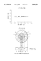
- FIG. 2 shows a structure of zirconia ferrule used for the fixed optical attenuator using the optical fiber according to the first embodiment of the present invention (Example 1).
- FIG. 3 shows a structure of the optical attenuator of SC type using the optical fiber according to the first embodiment of the present invention (Example 1).
- FIG. 4 is a graph showing the result of measurement of wavelength dependency of attenuation at 1.3 ⁇ m band for the first embodiment of the present invention (Example 1).
- FIG. 5 is a graph showing the result of measurement of wavelength dependency of attenuation at 1.3 ⁇ m band for a comparative example of the first embodiment of the present invention (Example 1).
- FIG. 6 is a cross-sectional view of an optical fiber for optical attenuation according to the first embodiment of the present invention (Example 2) showing its refractive index distribution.
- FIG. 7 is a cross-sectional view of an optical fiber for optical attenuation according to the second embodiment of the present invention (Example 3) showing its refractive index distribution.
- FIG. 8 is a cross-sectional view of an optical fiber for optical attenuation according to the second embodiment of the present invention (Example 4) showing its refractive index distribution.
- FIG. 9 is a cross-sectional view of an optical fiber for optical attenuation according to the third embodiment of the present invention (Example 5) showing its refractive index distribution.
- FIG. 10 is a graph showing the result of measurement of wavelength dependency of attenuation at 1.55 ⁇ m band for the fixed attenuator of SC type of Example 5.
- FIG. 11 is a cross-sectional view of an optical fiber for optical attenuation according to the third embodiment of the present invention (Example 6) showing its refractive index distribution.
- FIG. 12 is a graph showing the result of measurement of wavelength dependency of attenuation for a conventional optical attenuator.
- FIG. 1 is a cross-sectional view of an optical fiber for optical attenuation according to the first embodiment of the present invention (Example 1) showing its refractive index distribution.
- the optical fiber comprised a core 1 for optical propagation, inner cladding 2 and outer cladding 3, a part for trapping cladding mode.
- the core 1 was made of quartz glass and doped with GeO 2 so that there should be a relative refractive-index difference between the core 1 and the cladding.
- the relative refractive-index difference between the core and the cladding was 0.3% with the core diameter of 8 ⁇ m.
- the cutoff wavelength was about 1.1 ⁇ m.
- the core 1 was further doped with Co (cobalt) so that the intensity of optical signals should be attenuated.
- Co is an element suitable for optical attenuation at 1.3 ⁇ m and 1.55 ⁇ m wavelength band.
- the Co content was adjusted so that optical attenuation at a wavelength of 1.31 ⁇ m should be 30 dB with the fiber length of 22.4 mm.
- the inner cladding 2 was made of pure quartz glass and its outer diameter was about 40 ⁇ m.
- the outer cladding was doped with GeO 2 like the core, and its content was gradually increased from its inner side to outer side and its outer superficial part had such a GeO 2 content that a substantially constant relative refractive-index difference of 0.15% should be obtained.
- the outer diameter of the outer cladding was 125 ⁇ m, similar to that of an optical fiber of standard type. As to the relative refractive-index difference, the cladding was about a half of the core. However, since it was sufficiently remote from the core, optical signals propagated in the core were not affected.
- FIG. 2 shows an exemplary structure showing an example of way of use of the optical fiber described above, where the optical fiber is fixed in a zirconia ferrule.
- the optical fiber for optical attenuation 4 manufactured as described above is fixed in a zirconia ferrule 5 having a length of 22.4 mm.
- a zirconia ferrule is a conventional component for fixing optical fibers.
- the length of the optical fiber for optical attenuation 4 to be used was defined by the length of the zirconia ferrule 5 and attenuation of optical signals is determined by the length of the optical fiber for optical attenuation 4 and the content of doped Co.
- the length of the optical fiber for optical attenuation 4 is not particularly defined, for example, as in the case where single mode optical fibers of standard type were coupled to one or both ends of the optical fiber for optical attenuation 4, fixed attenuators with various attenuation degrees can be manufactured from one kind of the optical fiber for optical attenuation 4 by varying the length of the optical fiber for optical attenuation 4.
- FIG. 3 shows an example of fixed attenuator of SC type using the ferrule described above incorporated with the optical fiber for optical attenuation 4. It comprises a sleeve 6 and housing 7.
- the sleeve 6 is a component for adjusting the center axes of the optical fibers by applying uniform pressure to the ferrule of, for example, cylindrical shape, in its radial direction.
- the housing 7 is a container for the fixed attenuator of SC type.
- the above optical fiber can be manufactured at a cost lower than the one having a cladding throughout which is doped with an attenuating dopant, because an ordinary process for producing base materials of optical fibers can be used as it is for doping GeO 2 into the cladding of the optical fiber for optical attenuation 4 where a part of the cladding is doped with GeO 2 .
- Example 1 As a comparative sample for the Example 1 (first embodiment), an optical fiber for optical attenuation of which core had the same structure as the optical fiber of Example 1 and cladding was not doped with GeO 2 was prepared and a similar test was performed using the obtained optical fiber. Results of the measurement of wavelength dependency of attenuation at 1.3 ⁇ m band are shown in FIG. 5. As wavelength dependency, the attenuation showed periodically varying beats of a magnitude as large as ⁇ 5 dB and thus it was confirmed that attenuation could significantly change by a little change of the wavelength. This difference of the results clearly demonstrated the cladding mode eliminating effect of the optical fiber for optical attenuation of the present invention.
- FIG. 6 is a cross-sectional view of an optical fiber for optical attenuation according to the first embodiment of the present invention (Example 2) showing its refractive index distribution.
- the optical fiber comprised a core 1 for optical propagation, inner cladding 2, intermediate cladding 8, a part for trapping cladding mode, and outer cladding 3.
- the core 1 was made of quartz glass and doped with GeO 2 so that there should be a relative refractive-index difference between the core and the cladding.
- the relative refractive-index difference between the core and the cladding was 0.3% with the diameter of the core 1 of 8 ⁇ m.
- the cutoff wavelength was about 1.1 ⁇ m.
- the core 1 was doped with V (vandium) so that the intensity of optical signals should be attenuated.
- the V content was adjusted so that optical attenuation at a wavelength of 1.31 ⁇ m should be 20 dB with the fiber length of 22.4 mm.
- the inner cladding 2 and the outer cladding 3 was made of pure quartz glass.
- the outer diameter of the inner cladding 2 was about 75 ⁇ m and the outer diameter of the outer cladding was 125 ⁇ m, similar to that of an optical fiber of standard type.
- the intermediate cladding 8 was doped with GeO 2 like the core so that a substantially constant relative refractive-index difference of 0.3% should be obtained.
- the outer diameter of the intermediate cladding 8 was 100 ⁇ m.
- An optical attenuator of SC type was manufactured as described in Example 1 using this optical fiber for optical attenuation.
- optical attenuator of SC type comprising single mode optical fibers of standard type coupled to both ends of the optical attenuator, basic characteristics were measured at 1.3 ⁇ m band. The attenuation was very stable and no beat of attenuation was observed even though the wavelength was somewhat varied.
- FIG. 7 is a cross-sectional view of an optical fiber for optical attenuation according to the first embodiment of the present invention (Example 3) showing its refractive index distribution.
- the optical fiber comprised a core 1 for optical propagation, core center part 9 having optical attenuation property, inner cladding 2, and outer cladding 3, a part for trapping and attenuating cladding mode.
- the core 1 was made of quartz glass and doped with GeO 2 so that there should be a relative refractive-index difference between the core 1 and the cladding.
- the relative refractive-index difference between the core 1 and the cladding was 0.75% with the mode field diameter of about 8 ⁇ m, similar to that of dispersion shifted optical fibers.
- the cutoff wavelength was about 1.2 ⁇ m.
- the core center part 9 of the core 1 was doped with Co so that the intensity of optical signals should be attenuated.
- the doped Co content and the doped region (in the core center part) were adjusted so that optical attenuation at both wavelengths of 1.31 ⁇ m and 1.55 ⁇ m should be 25 dB with the fiber length of 22.4 mm.
- the inner cladding 2 was made of pure quartz glass and the outer diameter was about 85 ⁇ m.
- the outer cladding 3 was doped with GeO 2 like the core 1 so that a substantially constant relative refractive-index difference of 0.1% should be obtained.
- the outer cladding 3 was substantially uniformly doped with Co.
- the Co content was about one fifth of the Co content of the core 1.
- the outer diameter of the outer cladding was 125 ⁇ m, similar to that of optical fibers of standard type.
- An optical attenuator of SC type was manufactured as described in the example of the first embodiment (Example 1) using this optical fiber for optical attenuation.
- the same effect as described above can be expected for the case where the cladding is not doped with GeO 2 and the outer cladding is doped only with an attenuating dopant. If the amount of the attenuating dopant is larger than the amount used in this embodiment (Example 3), the influence of cladding mode would be more effectively reduced.
- the optical fiber can be manufactured at a cost lower than the one having a cladding throughout which is doped with an attenuating dopant, because a part of the cladding is doped with an attenuating dopant, though the cost may be higher than that of the first embodiment (Examples 1 and 2).
- FIG. 8 is a cross-sectional view of an optical fiber for optical attenuation according to the first and second embodiment of the present invention (Example 4) showing its refractive index distribution.
- the optical fiber comprised a core 1 for optical propagation, core center part 9 having optical attenuation property, inner cladding 2, intermediate cladding 8, a part for attenuating cladding mode, and outer cladding 3, a part for trapping cladding mode.
- the core 1 was made of quartz glass and doped with GeO 2 so that there should be a relative refractive-index difference between the core and the cladding.
- the relative refractive-index difference between the core 1 and the cladding was 0.75% with the mode field diameter of about 8 ⁇ m, similar to that of dispersion shifted optical fibers.
- the cutoff wavelength was about 1.2 ⁇ m.
- the core center part 9 of the core 1 was doped with Co so that the intensity of optical signals should be attenuated.
- the doped Co content and the doped region (in the core center part 9) were adjusted so that optical attenuation at both wavelengths of 1.31 ⁇ m and 1.55 ⁇ m should be 30 dB with the fiber length of 22.4 mm.
- the inner cladding 2 was made of pure quartz glass and the outer diameter was about 85 ⁇ m.
- the intermediate cladding 8 was substantially uniformly doped with Co.
- the Co content was about a half of the Co content of the core 1.
- the outer diameter of the intermediate cladding 8 was 100 ⁇ m.
- the outer cladding 3 was doped with GeO 2 like the core 1 so that a substantially constant relative refractive-index difference of 0.2% should be obtained.
- the outer diameter of the outer cladding was 125 ⁇ m, similar to that of optical fibers of standard type.
- An optical attenuator of SC type was manufactured as described in the example of the first embodiment (Example 1) using this optical fiber for optical attenuation.
- Example 3 The same test as in Example 3 was performed using this optical attenuator of SC type.
- the attenuation was very stable in the 1.31 ⁇ m and 1.55 ⁇ m bands and no beat of attenuation was observed even though the wavelength was somewhat varied.
- an optical fiber for optical attenuation where the core had the same structure as the optical fiber of Example 4 and Co was doped throughout the cladding was intended.
- doping throughout the cladding at a concentration similar to that of the core 1 requires many production steps and hence an optical fiber for optical attenuation of the intended type becomes very expensive and has little practical usefulness. Therefore, prepared was an optical fiber wherein only a part of cladding in the vicinity of the core, which had an outer diameter of 50 ⁇ m, was doped with Co at a content similar to that of the core. Similar test was performed using this optical fiber.
- the wavelength dependency of attenuation periodically varying beats of attenuation of about 1.5 dB was observed for both of the wavelength bands. Thus, cladding mode eliminating effect was insufficient.
- the attenuating dopant doped in the core 1 or in the vicinity of the core 1 comprised of one kind of dopant.
- the attenuating dopant doped in the core 1 or in the vicinity of the core 1 is doped to control the basic characteristics for optical attenuation and is not limited to one composed of one kind of dopant.
- the attenuating dopant doped in the cladding two or more dopants may be doped as the case may be, since it is not necessary to expand the doped region. In short, it is important to select the most effective doping method.
- FIG. 9 is a cross-sectional view of an optical fiber for optical attenuation according to the third embodiment of the present invention showing its refractive index distribution.
- the optical fiber comprised a core 1 for optical propagation, inner cladding 2, outer cladding 3 and a low refractive index part 10.
- the core 1 was made of quartz glass and doped with GeO 2 so that there should be a relative refractive-index difference between the core 1 and the inner cladding 2.
- the core diameter was 8 ⁇ m and the relative refractive-index difference between the core 1 and the inner cladding 2 was 0.3%.
- the cutoff wavelength was about 1.1 ⁇ m.
- the core was further doped with Co (cobalt) so that the intensity of optical signals should be attenuated.
- the Co content was adjusted so that optical attenuation at a wavelength of 1.55 ⁇ m should be 30 dB with the fiber length of 22 mm.
- the inner cladding 2 was a trapping part for cladding mode and doped with Co substantially uniformly.
- the inner cladding 2 had an outer diameter of about 40 ⁇ m.
- the Co content was about a half of that of the core 1, and the Co doping amount in the core 1 could be reduced by the doping of Co, since the refractive index was substantially unchanged by the doping of Co.
- the outer cladding 3 was made of pure quartz glass and the outer diameter of the outer cladding, i.e., the outer diameter of the optical fiber for optical attenuation of this example was 125 ⁇ m, similar to that of an optical fiber of standard type.
- the low refractive index part 10 was composed of a layer doped uniformly with F (fluorine) and having a thickness of 15 ⁇ m, which is present outside the inner cladding 2 and inside the outer cladding 3, and the doped content of F was adjusted so that a substantially constant relative refractive-index difference of -0.15% should be obtained.
- F fluorine
- optical signals propagated in the core 1 were not substantially affected by the relative refractive-index difference of the low refractive index part 10.
- An optical attenuator of SC type as shown in FIG. 3 was manufactured as described in Example 1 using the optical fiber obtained above.
- the ferrule 6 had a length of about 22 mm and its end surfaces had been subjected to advanced PC polishing.
- this optical attenuator of SC type comprising single mode optical fibers of standard type coupled to its both ends, basic characteristics were measured at 1.55 ⁇ m band. Results of the measurement of wavelength dependency of attenuation at 1.55 ⁇ m band are shown in FIG. 10. As seen from this figure, the attenuation degree of 30 dB was obtained very stably and no beat of attenuation was observed even though the wavelength was somewhat varied.
- the region to be doped with an attenuating dopant may be small since the region of the inner cladding 2 is small.
- technique for doping F into the low refractive index part 10 is widely used one and an ordinary process for producing base materials of optical fibers can be used as it is. Therefore, the optical fiber of the third embodiment can be manufactured at a cost lower than the cost for the conventional ones having a cladding throughout which is doped with an attenuating dopant.
- optical signals radiated from the core 1 to the inner cladding 2 and propagated are confined in the inner cladding 2 by providing a layer having a thickness of 15 ⁇ m and doped uniformly with F (fluorine) so that a substantially constant relative refractive-index difference of -0.15% should be obtained in the low refractive index part 10 outside the inner cladding 2.
- F fluorine
- by substantially uniformly doping the core 1 and the inner cladding 2 with Co as a dopant propagating optical signals are attenuated by the dopant of Co.
- the influence of cladding mode can be reduced. That is, cladding mode can be effectively reduced by local doping of the inner cladding 2, not doping of the whole optical fiber for optical attenuation.
- optical fibers for optical attenuation can be produced at a low cost.
- refractive indices of the core 1 and the inner cladding 2 were not substantially changed by the doping of Co. Therefore, coupling characteristics such as reflection characteristic advantageously suffer from no influence of the doping.
- the method for varying the relative refractive-index difference of the outer side of the inner cladding 2, i.e., inner side of the outer cladding 3, has already become a conventional method and therefore conventional apparatuses for manufacturing optical fibers can advantageously used. Moreover, because the region where the relative refractive-index difference is changed is small, optical fibers for optical attenuation can be produced at a further lower cost.
- the dopant for optical attenuation doped in the core 1 or in the vicinity of the core 1 comprised of one kind of dopant.
- the attenuating dopant doped in the core 1 or in the vicinity of the core 1 is doped to control the basic characteristics for optical attenuation and therefore is of course not limited to one comprising one kind of dopant.
- two or more dopants such as Cr (chromium) and V (vanadium) may of course be doped as the case may be, for example, when intended wavelength bands and/or fiber parameters are varied, since it is not necessary to expand the doped region.
- FIG. 11 is a cross-sectional view of example of the optical fiber for optical attenuation according to the third embodiment of the present invention, which view shows the refractive index distribution.
- the optical fiber comprised an optical attenuation dopant region 9.
- the optical attenuation dopant region 9 was a region doped with, for example, Co, and it was a region of the inner cladding 2 directly adjacent to the core 1.
- the core 1 of the optical fiber of this example was also doped with Co in addition to GeO 2 like the one in Example 5. That is, the optical fiber of this example had a region corresponding to the region of the optical fiber for optical attenuation of Example 5 doped with the dopant as a part of the inner cladding 2.
- the optical attenuation dopant region 9 doped with Co and the region not doped with Co were not substantially different from each other in their refractive index distributions and therefore the refractive index distribution shown in FIG. 11 could be obtained.
- the core had the highest refractive index.
- the inner cladding 2 comprising the optical attenuation dopant region 9 outside the core 1, and the low refractive index part 10, of which refractive index was lower than that of the inner cladding 2, outside the inner cladding 2.
- optical signals entered into the inner cladding 2 is confined within the inner cladding 2 comprising the optical attenuation dopant region 9 and attenuated by the optical attenuation dopant region 9. Accordingly, the optical fiber exerts the same effect as in the optical fiber for optical attenuation of Example 5.
- the region doped with the dopant can be made small, it can be produced at a cost still lower than that of the optical fiber for optical attenuation of Example 5.
- the whole core 1 was doped with the dopant in this example, only a part may of course be doped like the inner cladding 2.
- Example 5 As a comparative sample for that of Example 5 (third embodiment), an optical fiber for optical attenuation whose core had the same structure as the optical fiber of Example 5 and whose cladding was made of pure quartz glass, i.e., not doped with GeO 2 , was prepared. A similar test was performed using an optical attenuator of SC type comprising the obtained optical fiber.
- the amount of Co doped in the core had to be larger than those used in the optical fibers of Examples 5 and 6.
- the wavelength dependency of attenuation showed periodically varying beats of a magnitude as large as ⁇ 5 dB and, from these results, it was confirmed that attenuation could significantly change by a little change of the wavelength. Further, optical signals sometimes could not propagate properly due to coupling of cladding mode.
- optical fiber with the invention can be applied to the terminator with simple structure because the reflected optical power attenuated effecively only by using the optical fiber without any special end-treatment.
- kind, amount, doping method and the like of the dopant for the optical fiber for optical attenuation of the present invention are not limited to those described in the above examples.
- the fiber functions as the mode filter which effectively attenuates only the cladding propagation modes.
- (1) cladding mode can be effectively reduced without affecting the attenuating characteristics of optical attenuators (first and second embodiments).
- the mode field shape of basic mode is not altered when refractive index of the trapping part is changed and the basic characteristics such as attenuation wavelength characteristic of optical attenuators are not altered when an attenuating dopant is added to the trapping part. Therefore, characteristics of optical attenuation can be controlled only by structures around the core(first and second embodiments).
- the cladding can be produced by only a conventional apparatus for producing optical fibers(first and second embodiments).
Abstract
Description
Claims (26)
Applications Claiming Priority (4)
| Application Number | Priority Date | Filing Date | Title |
|---|---|---|---|
| JP00000496A JP3271886B2 (en) | 1996-01-04 | 1996-01-04 | Optical attenuating optical fiber |
| JP8-000004 | 1996-01-04 | ||
| JP8-126633 | 1996-05-22 | ||
| JP12663396A JP3209497B2 (en) | 1996-05-22 | 1996-05-22 | Optical attenuating optical fiber |
Publications (1)
| Publication Number | Publication Date |
|---|---|
| US5841926A true US5841926A (en) | 1998-11-24 |
Family
ID=26332908
Family Applications (1)
| Application Number | Title | Priority Date | Filing Date |
|---|---|---|---|
| US08/777,205 Expired - Lifetime US5841926A (en) | 1996-01-04 | 1996-12-27 | Optical fibers for optical attenuation |
Country Status (3)
| Country | Link |
|---|---|
| US (1) | US5841926A (en) |
| EP (1) | EP0783117B1 (en) |
| DE (1) | DE69734031T2 (en) |
Cited By (26)
| Publication number | Priority date | Publication date | Assignee | Title |
|---|---|---|---|---|
| US6078715A (en) * | 1997-06-13 | 2000-06-20 | Sumitomo Electric Industries, Ltd. | Optical fiber |
| EP1146356A1 (en) * | 1999-10-22 | 2001-10-17 | Showa Electric Wire and Cable Co.,Ltd. | Optical attenuator |
| US6327403B1 (en) * | 1999-06-10 | 2001-12-04 | Lasercomm Inc. | Reducing mode interference in transmission of LP02 Mode in optical fibers |
| US6411762B1 (en) * | 1997-12-09 | 2002-06-25 | Scientific-Atlanta, Inc. | Optical fiber with irregularities at cladding boundary |
| US20020106181A1 (en) * | 2001-02-02 | 2002-08-08 | Won-Taek Han | Optical fiber and planar waveguide for achieving a substantially uniform optical attenuation |
| US6490391B1 (en) | 2000-07-12 | 2002-12-03 | Oluma, Inc. | Devices based on fibers engaged to substrates with grooves |
| US6496643B1 (en) * | 2000-10-25 | 2002-12-17 | Itf Optical Technologies Inc. | Internal termination for optical fibers |
| US6498888B1 (en) * | 1998-04-22 | 2002-12-24 | Institut National D'optique | High-attenuation fiber with cladding mode suppression for all-fiber optical attenuator |
| US6501875B2 (en) | 2000-06-27 | 2002-12-31 | Oluma, Inc. | Mach-Zehnder inteferometers and applications based on evanescent coupling through side-polished fiber coupling ports |
| US6516114B2 (en) | 2000-06-27 | 2003-02-04 | Oluma, Inc. | Integration of fibers on substrates fabricated with grooves |
| US6542663B1 (en) | 2000-09-07 | 2003-04-01 | Oluma, Inc. | Coupling control in side-polished fiber devices |
| US6571035B1 (en) | 2000-08-10 | 2003-05-27 | Oluma, Inc. | Fiber optical switches based on optical evanescent coupling between two fibers |
| US6597833B1 (en) | 2000-06-27 | 2003-07-22 | Oluma, Inc. | Wavelength-division multiplexers and demultiplexers based on mach-zehnder interferometers and evanescent coupling |
| WO2003065099A1 (en) * | 2002-01-29 | 2003-08-07 | Nippon Electric Glass Co., Ltd. | Optical device and method of manufacturing the optical device |
| US6621951B1 (en) | 2000-06-27 | 2003-09-16 | Oluma, Inc. | Thin film structures in devices with a fiber on a substrate |
| US6621952B1 (en) | 2000-08-10 | 2003-09-16 | Oluma, Inc. | In-fiber variable optical attenuators and modulators using index-changing liquid media |
| US6625349B2 (en) | 2000-06-27 | 2003-09-23 | Oluma, Inc. | Evanescent optical coupling between a waveguide formed on a substrate and a side-polished fiber |
| US6681072B2 (en) * | 2000-08-28 | 2004-01-20 | Sumitomo Electric Industries Co., Ltd. | Optical fiber, method of making optical fiber preform, and method of making optical fiber |
| US6744948B1 (en) | 2001-06-20 | 2004-06-01 | Oluma, Inc. | Fiber tap monitor based on evanescent coupling |
| US20040114903A1 (en) * | 2002-11-27 | 2004-06-17 | Masamitsu Yamaguchi | Optical fiber for attenuating optical signal |
| US20040114897A1 (en) * | 2002-12-10 | 2004-06-17 | Sumitomo Electric Industries, Ltd. | Optical fiber |
| US20040218862A1 (en) * | 2000-09-21 | 2004-11-04 | Nec Corporation | Wavelength dispersion compensator and optical transmission line |
| US20050175284A1 (en) * | 2002-07-25 | 2005-08-11 | Morita Kazuaki | Optical filter |
| US20060245707A1 (en) * | 2005-05-02 | 2006-11-02 | Lucent Technologies, Inc. | Optical transmission fiber with a glass guiding cladding |
| WO2008110668A1 (en) * | 2007-03-15 | 2008-09-18 | Liekki Oy | Optical fiber structure and a method of producing thereof |
| US10162109B2 (en) | 2017-02-07 | 2018-12-25 | Corning Incorporated | Multimode optical fibers for attenuators |
Families Citing this family (9)
| Publication number | Priority date | Publication date | Assignee | Title |
|---|---|---|---|---|
| CA2341670A1 (en) | 1998-08-25 | 2000-03-02 | Wolfgang Dultz | Plastic optical fiber |
| US6434311B1 (en) | 1999-06-10 | 2002-08-13 | Lasercomm Inc. | Reducing mode interference in transmission of a high order mode in optical fibers |
| GB2379279B (en) * | 2001-08-31 | 2005-10-26 | Gsi Lumonics Ltd | Laser processing system and optical fibres |
| IL147554A (en) | 2002-01-10 | 2005-11-20 | Kiloambda Ip Ltd | Optical limiter |
| JPWO2003067723A1 (en) * | 2002-02-06 | 2005-06-02 | 三菱電機株式会社 | Multimode optical fiber, fiber laser amplifier and fiber laser oscillator |
| EP1467239B1 (en) * | 2003-04-09 | 2011-09-21 | KiloLambda Technologies Ltd. | Optical power limiter |
| JP4047232B2 (en) * | 2003-06-18 | 2008-02-13 | 株式会社フジクラ | Mode converter for high-order mode fiber |
| GB2444091A (en) | 2006-11-24 | 2008-05-28 | Gsi Group Ltd | A Laser Amplifier |
| JP5910087B2 (en) * | 2011-02-25 | 2016-04-27 | 住友電気工業株式会社 | Light receiving method and separation device for light output from multi-core optical fiber |
Citations (6)
| Publication number | Priority date | Publication date | Assignee | Title |
|---|---|---|---|---|
| US4610506A (en) * | 1983-01-11 | 1986-09-09 | Hitachi Cable, Ltd. | Single polarization optical fibers |
| JPH0589784A (en) * | 1991-09-30 | 1993-04-09 | Nec Corp | Plasma display panel |
| JPH05264816A (en) * | 1992-03-19 | 1993-10-15 | Showa Electric Wire & Cable Co Ltd | Optical attenuator |
| JPH05267710A (en) * | 1992-01-29 | 1993-10-15 | General Electric Co <Ge> | Amorphous multilayered avalanche photodiode |
| JPH06109923A (en) * | 1992-09-28 | 1994-04-22 | Seiko Instr Inc | Optical attenuator |
| US5509101A (en) * | 1994-07-11 | 1996-04-16 | Corning Incorporated | Radiation resistant optical waveguide fiber and method of making same |
Family Cites Families (11)
| Publication number | Priority date | Publication date | Assignee | Title |
|---|---|---|---|---|
| JPS5264816A (en) * | 1975-11-25 | 1977-05-28 | Oki Electric Ind Co Ltd | Signal sending unit for exchange |
| JPS542754A (en) * | 1977-06-08 | 1979-01-10 | Toshiba Corp | Stationary attenuator for optical fiber communication |
| JPS574006A (en) * | 1980-06-09 | 1982-01-09 | Toshiba Corp | Attenuator for optical fiber and its production |
| US4852968A (en) * | 1986-08-08 | 1989-08-01 | American Telephone And Telegraph Company, At&T Bell Laboratories | Optical fiber comprising a refractive index trench |
| JPS6396504U (en) | 1986-12-11 | 1988-06-22 | ||
| JPS6396506U (en) | 1986-12-12 | 1988-06-22 | ||
| GB8713081D0 (en) * | 1987-06-04 | 1987-07-08 | Pirelli General Plc | Optical fibre attenuators |
| US4877306A (en) * | 1987-09-30 | 1989-10-31 | Corning Glass Works | Coated optical waveguide fibers |
| JPH0361547U (en) | 1989-10-23 | 1991-06-17 | ||
| JPH07118663B2 (en) | 1993-04-16 | 1995-12-18 | 日本電気株式会社 | Signal detection circuit |
| JP3233503B2 (en) * | 1993-07-29 | 2001-11-26 | 昭和電線電纜株式会社 | Optical attenuator |
-
1996
- 1996-12-27 US US08/777,205 patent/US5841926A/en not_active Expired - Lifetime
-
1997
- 1997-01-03 EP EP97100057A patent/EP0783117B1/en not_active Expired - Lifetime
- 1997-01-03 DE DE69734031T patent/DE69734031T2/en not_active Expired - Lifetime
Patent Citations (6)
| Publication number | Priority date | Publication date | Assignee | Title |
|---|---|---|---|---|
| US4610506A (en) * | 1983-01-11 | 1986-09-09 | Hitachi Cable, Ltd. | Single polarization optical fibers |
| JPH0589784A (en) * | 1991-09-30 | 1993-04-09 | Nec Corp | Plasma display panel |
| JPH05267710A (en) * | 1992-01-29 | 1993-10-15 | General Electric Co <Ge> | Amorphous multilayered avalanche photodiode |
| JPH05264816A (en) * | 1992-03-19 | 1993-10-15 | Showa Electric Wire & Cable Co Ltd | Optical attenuator |
| JPH06109923A (en) * | 1992-09-28 | 1994-04-22 | Seiko Instr Inc | Optical attenuator |
| US5509101A (en) * | 1994-07-11 | 1996-04-16 | Corning Incorporated | Radiation resistant optical waveguide fiber and method of making same |
Cited By (40)
| Publication number | Priority date | Publication date | Assignee | Title |
|---|---|---|---|---|
| US6078715A (en) * | 1997-06-13 | 2000-06-20 | Sumitomo Electric Industries, Ltd. | Optical fiber |
| US6411762B1 (en) * | 1997-12-09 | 2002-06-25 | Scientific-Atlanta, Inc. | Optical fiber with irregularities at cladding boundary |
| US6498888B1 (en) * | 1998-04-22 | 2002-12-24 | Institut National D'optique | High-attenuation fiber with cladding mode suppression for all-fiber optical attenuator |
| US6327403B1 (en) * | 1999-06-10 | 2001-12-04 | Lasercomm Inc. | Reducing mode interference in transmission of LP02 Mode in optical fibers |
| EP1146356A1 (en) * | 1999-10-22 | 2001-10-17 | Showa Electric Wire and Cable Co.,Ltd. | Optical attenuator |
| US6748151B1 (en) * | 1999-10-22 | 2004-06-08 | Showa Electric Wire & Cable Co., Ltd. | Optical fiber attenuator with attenuating dopant limited to a central or peripheral area of the fiber core |
| EP1146356A4 (en) * | 1999-10-22 | 2005-04-27 | Showa Electric Wire & Cable Co | Optical attenuator |
| US6625349B2 (en) | 2000-06-27 | 2003-09-23 | Oluma, Inc. | Evanescent optical coupling between a waveguide formed on a substrate and a side-polished fiber |
| US6501875B2 (en) | 2000-06-27 | 2002-12-31 | Oluma, Inc. | Mach-Zehnder inteferometers and applications based on evanescent coupling through side-polished fiber coupling ports |
| US6516114B2 (en) | 2000-06-27 | 2003-02-04 | Oluma, Inc. | Integration of fibers on substrates fabricated with grooves |
| US6621951B1 (en) | 2000-06-27 | 2003-09-16 | Oluma, Inc. | Thin film structures in devices with a fiber on a substrate |
| US6556746B1 (en) | 2000-06-27 | 2003-04-29 | Oluma, Inc. | Integrated fiber devices based on Mach-Zehnder interferometers and evanescent optical coupling |
| US6597833B1 (en) | 2000-06-27 | 2003-07-22 | Oluma, Inc. | Wavelength-division multiplexers and demultiplexers based on mach-zehnder interferometers and evanescent coupling |
| US6490391B1 (en) | 2000-07-12 | 2002-12-03 | Oluma, Inc. | Devices based on fibers engaged to substrates with grooves |
| US6690857B2 (en) | 2000-07-12 | 2004-02-10 | Oluma, Inc. | Fiber devices having side evanescent coupling port |
| US6571035B1 (en) | 2000-08-10 | 2003-05-27 | Oluma, Inc. | Fiber optical switches based on optical evanescent coupling between two fibers |
| US6621952B1 (en) | 2000-08-10 | 2003-09-16 | Oluma, Inc. | In-fiber variable optical attenuators and modulators using index-changing liquid media |
| US6892019B2 (en) | 2000-08-28 | 2005-05-10 | Sumitomo Electric Industries, Ltd. | Optical fiber, method of making optical fiber preform, and method of making optical fiber |
| US6681072B2 (en) * | 2000-08-28 | 2004-01-20 | Sumitomo Electric Industries Co., Ltd. | Optical fiber, method of making optical fiber preform, and method of making optical fiber |
| US20040151455A1 (en) * | 2000-08-28 | 2004-08-05 | Sumitomo Electric Industries, Ltd. | Optical fiber, method of making optical fiber preform, and method of making optical fiber |
| US6542663B1 (en) | 2000-09-07 | 2003-04-01 | Oluma, Inc. | Coupling control in side-polished fiber devices |
| US6952509B2 (en) * | 2000-09-21 | 2005-10-04 | Nec Corporation | Wavelength dispersion compensator and optical transmission line |
| US20040218862A1 (en) * | 2000-09-21 | 2004-11-04 | Nec Corporation | Wavelength dispersion compensator and optical transmission line |
| US6496643B1 (en) * | 2000-10-25 | 2002-12-17 | Itf Optical Technologies Inc. | Internal termination for optical fibers |
| US20020106181A1 (en) * | 2001-02-02 | 2002-08-08 | Won-Taek Han | Optical fiber and planar waveguide for achieving a substantially uniform optical attenuation |
| US6757473B2 (en) * | 2001-02-02 | 2004-06-29 | Optonest Corporation | Optical fiber and planar waveguide for achieving a substantially uniform optical attenuation |
| US6744948B1 (en) | 2001-06-20 | 2004-06-01 | Oluma, Inc. | Fiber tap monitor based on evanescent coupling |
| WO2003065099A1 (en) * | 2002-01-29 | 2003-08-07 | Nippon Electric Glass Co., Ltd. | Optical device and method of manufacturing the optical device |
| US20070137255A1 (en) * | 2002-01-29 | 2007-06-21 | Taisei Miyake | Optical device and method of manufacturing the optical same |
| US20050175284A1 (en) * | 2002-07-25 | 2005-08-11 | Morita Kazuaki | Optical filter |
| US7092610B2 (en) * | 2002-11-27 | 2006-08-15 | Showa Electric Wire & Cable Co. Ltd. | Optical fiber for attenuating optical signal |
| US20040114903A1 (en) * | 2002-11-27 | 2004-06-17 | Masamitsu Yamaguchi | Optical fiber for attenuating optical signal |
| US6985660B2 (en) * | 2002-12-10 | 2006-01-10 | Sumitomo Electric Industries, Ltd. | Multiple cladding optical fiber |
| US20040114897A1 (en) * | 2002-12-10 | 2004-06-17 | Sumitomo Electric Industries, Ltd. | Optical fiber |
| US20060245707A1 (en) * | 2005-05-02 | 2006-11-02 | Lucent Technologies, Inc. | Optical transmission fiber with a glass guiding cladding |
| US7215860B2 (en) * | 2005-05-02 | 2007-05-08 | Lucent Technologies Inc. | Optical transmission fiber with a glass guiding cladding |
| WO2008110668A1 (en) * | 2007-03-15 | 2008-09-18 | Liekki Oy | Optical fiber structure and a method of producing thereof |
| US20100220965A1 (en) * | 2007-03-15 | 2010-09-02 | Liekki Oy | Optical fiber structure and a method of producing thereof |
| US8620126B2 (en) | 2007-03-15 | 2013-12-31 | Nlight Oy | Optical fiber structure and a method of producing thereof |
| US10162109B2 (en) | 2017-02-07 | 2018-12-25 | Corning Incorporated | Multimode optical fibers for attenuators |
Also Published As
| Publication number | Publication date |
|---|---|
| EP0783117A2 (en) | 1997-07-09 |
| EP0783117A3 (en) | 2000-03-22 |
| EP0783117B1 (en) | 2005-08-24 |
| DE69734031T2 (en) | 2006-03-30 |
| DE69734031D1 (en) | 2005-09-29 |
Similar Documents
| Publication | Publication Date | Title |
|---|---|---|
| US5841926A (en) | Optical fibers for optical attenuation | |
| KR960001319B1 (en) | Optical fiber | |
| EP1722256B1 (en) | Optical fiber filter for suppression of amplified spontaneous emission | |
| RU2168190C2 (en) | Optical fiber with positive dispersion | |
| EP0674193B1 (en) | Dispersion compensating optical fiber and optical transmission system including such fiber | |
| EP0721119B1 (en) | Controlled dispersion optical waveguide | |
| US5613027A (en) | Dispersion shifted optical waveguide fiber | |
| KR910000718B1 (en) | Optical fiber for propagating single mode single polarized wave | |
| CA1202506A (en) | Low loss single mode fiber | |
| EP1489444B1 (en) | Higher order mode dispersion compensating fiber and mode converter for higher order fiber | |
| US5572618A (en) | Optical attenuator | |
| US5883990A (en) | Low transmission loss optical fiber having a grating | |
| KR19990029743A (en) | Single mode optical waveguide fiber with damper | |
| US6282342B1 (en) | Monolithic coaxial device | |
| CA1248386A (en) | Quadruple-clad optical fiberguide | |
| KR920001217B1 (en) | Single mode lightguide fiber having a trapezoidal refractive index profile | |
| EP1113314A1 (en) | Optical fiber | |
| EP0798578A1 (en) | Dispersion shifted optical waveguide fiber | |
| JP3271886B2 (en) | Optical attenuating optical fiber | |
| JP3209497B2 (en) | Optical attenuating optical fiber | |
| AU753653B2 (en) | Highly non-linear single mode waveguide | |
| KR20010101087A (en) | Optical attenuator | |
| US7218823B2 (en) | Method and device for spectral filtering | |
| CN112859245B (en) | Double-core terahertz optical fiber coupler | |
| Stone et al. | F: End filters: etalon on the beveled facet of a fiber with an outdiffused core |
Legal Events
| Date | Code | Title | Description |
|---|---|---|---|
| AS | Assignment |
Owner name: NIPPON TELEGRAPH AND TELEPHONE CORPORATION, JAPAN Free format text: ASSIGNMENT OF ASSIGNORS INTEREST;ASSIGNORS:TAKEUCHI, YOSHIAKI;NAGASE, RYO;MITACHI, SEIKO;AND OTHERS;REEL/FRAME:008386/0533 Effective date: 19961225 Owner name: SHOWA ELECTRIC WIRE & CABLE CO., LTD., JAPAN Free format text: ASSIGNMENT OF ASSIGNORS INTEREST;ASSIGNORS:TAKEUCHI, YOSHIAKI;NAGASE, RYO;MITACHI, SEIKO;AND OTHERS;REEL/FRAME:008386/0533 Effective date: 19961225 |
|
| STCF | Information on status: patent grant |
Free format text: PATENTED CASE |
|
| FEPP | Fee payment procedure |
Free format text: PAYOR NUMBER ASSIGNED (ORIGINAL EVENT CODE: ASPN); ENTITY STATUS OF PATENT OWNER: LARGE ENTITY |
|
| CC | Certificate of correction | ||
| FPAY | Fee payment |
Year of fee payment: 4 |
|
| FPAY | Fee payment |
Year of fee payment: 8 |
|
| AS | Assignment |
Owner name: SWCC SHOWA DEVICE TECHNOLOGY CO., LTD., JAPAN Free format text: ASSIGNMENT OF ASSIGNORS INTEREST;ASSIGNOR:SHOWA ELECTRIC WIRE AND CABLE CO., LTD.;REEL/FRAME:018194/0728 Effective date: 20060724 |
|
| AS | Assignment |
Owner name: SWCC SHOWA CABLE SYSTEMS, CO., LTD., JAPAN Free format text: ASSIGNMENT OF ASSIGNORS INTEREST;ASSIGNOR:SWCC SHOWA DEVICE TECHNOLOGY CO., LTD.;REEL/FRAME:020540/0357 Effective date: 20080115 |
|
| FPAY | Fee payment |
Year of fee payment: 12 |