EP2679849B1 - Flüssigkeitsreibungskupplung - Google Patents
Flüssigkeitsreibungskupplung Download PDFInfo
- Publication number
- EP2679849B1 EP2679849B1 EP12004767.5A EP12004767A EP2679849B1 EP 2679849 B1 EP2679849 B1 EP 2679849B1 EP 12004767 A EP12004767 A EP 12004767A EP 2679849 B1 EP2679849 B1 EP 2679849B1
- Authority
- EP
- European Patent Office
- Prior art keywords
- friction clutch
- fluid friction
- valve
- fluid
- clutch according
- Prior art date
- Legal status (The legal status is an assumption and is not a legal conclusion. Google has not performed a legal analysis and makes no representation as to the accuracy of the status listed.)
- Revoked
Links
- 239000012530 fluid Substances 0.000 title claims description 54
- 230000008878 coupling Effects 0.000 title description 11
- 238000010168 coupling process Methods 0.000 title description 11
- 238000005859 coupling reaction Methods 0.000 title description 11
- 230000004888 barrier function Effects 0.000 claims description 2
- 230000004907 flux Effects 0.000 claims description 2
- 230000037431 insertion Effects 0.000 claims 1
- 238000003780 insertion Methods 0.000 claims 1
- 238000010586 diagram Methods 0.000 description 3
- 230000001419 dependent effect Effects 0.000 description 2
- 240000006829 Ficus sundaica Species 0.000 description 1
- 230000005540 biological transmission Effects 0.000 description 1
- 238000011161 development Methods 0.000 description 1
- 230000018109 developmental process Effects 0.000 description 1
- 230000000694 effects Effects 0.000 description 1
- 239000007788 liquid Substances 0.000 description 1
- 238000005086 pumping Methods 0.000 description 1
- 230000004044 response Effects 0.000 description 1
- 238000010008 shearing Methods 0.000 description 1
- 230000001502 supplementing effect Effects 0.000 description 1
Images


Classifications
-
- F—MECHANICAL ENGINEERING; LIGHTING; HEATING; WEAPONS; BLASTING
- F16—ENGINEERING ELEMENTS AND UNITS; GENERAL MEASURES FOR PRODUCING AND MAINTAINING EFFECTIVE FUNCTIONING OF MACHINES OR INSTALLATIONS; THERMAL INSULATION IN GENERAL
- F16D—COUPLINGS FOR TRANSMITTING ROTATION; CLUTCHES; BRAKES
- F16D35/00—Fluid clutches in which the clutching is predominantly obtained by fluid adhesion
- F16D35/02—Fluid clutches in which the clutching is predominantly obtained by fluid adhesion with rotary working chambers and rotary reservoirs, e.g. in one coupling part
- F16D35/021—Fluid clutches in which the clutching is predominantly obtained by fluid adhesion with rotary working chambers and rotary reservoirs, e.g. in one coupling part actuated by valves
- F16D35/022—Fluid clutches in which the clutching is predominantly obtained by fluid adhesion with rotary working chambers and rotary reservoirs, e.g. in one coupling part actuated by valves the valve being actuated by a bimetallic strip
-
- F—MECHANICAL ENGINEERING; LIGHTING; HEATING; WEAPONS; BLASTING
- F16—ENGINEERING ELEMENTS AND UNITS; GENERAL MEASURES FOR PRODUCING AND MAINTAINING EFFECTIVE FUNCTIONING OF MACHINES OR INSTALLATIONS; THERMAL INSULATION IN GENERAL
- F16D—COUPLINGS FOR TRANSMITTING ROTATION; CLUTCHES; BRAKES
- F16D35/00—Fluid clutches in which the clutching is predominantly obtained by fluid adhesion
- F16D35/02—Fluid clutches in which the clutching is predominantly obtained by fluid adhesion with rotary working chambers and rotary reservoirs, e.g. in one coupling part
- F16D35/021—Fluid clutches in which the clutching is predominantly obtained by fluid adhesion with rotary working chambers and rotary reservoirs, e.g. in one coupling part actuated by valves
- F16D35/024—Fluid clutches in which the clutching is predominantly obtained by fluid adhesion with rotary working chambers and rotary reservoirs, e.g. in one coupling part actuated by valves the valve being actuated electrically, e.g. by an electromagnet
Definitions
- the invention relates to a fluid friction clutch according to the preamble of claim 1.
- Such a fluid friction clutch is from the WO 2007/0163 14 A1
- the disclosure of which is hereby made by explicit reference to the disclosure content of the present application.
- the clutch performance can be further improved by providing a return pump which rotates at secondary or primary speed and, due to its location, scrapes off clutch fluid from the clutch plate and housing.
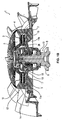
- Fig. 1A is a sectional view of a fluid friction clutch 1 according to the invention shown, which has a housing which is usually constructed of a housing body 2 and a lid 3.
- a clutch disc 4 is arranged, which is rotatable relative to the housing 2, 3.
- the relative to the housing 2, 3 rotatable clutch disc 4 is in this case rotatably disposed at one end 5 of a centrally mounted within the housing 2, 3 shaft 6.
- On the housing 2, 3 is a schematically shown slightly simplified drivable active member 7 fixed, which may be formed for example as a fan.
- a working chamber 9 is arranged between the housing 2, 3 and the clutch disc 4, which, as shown Fig. 1A can be seen, working column 15, due to a shearing effect on the working chamber 9 supplied coupling fluid make a torque transmission possible.
- a storage chamber 10 is provided for said coupling liquid, wherein a feed channel 11a, 11b leads from the storage chamber 10 to the working chamber 9 and thus forms the flow.
- a return pumping system or a return pump 16 which serves for the return of coupling fluid from the working chamber 9 to the storage chamber 10.
- This return pump is either formed by the resulting centrifugal force, which pumps 9 to evacuate the working chamber fluid to the storage chamber 10 to the outside.
- a separate component in the form of an active return pump as shown schematically in the hydraulic diagram of Fig. 7 and 8th is indicated, which acts on shear force.
- the fluid friction clutch 1 further comprises a stationary coupling part 13, which is rotatable relative to the housing 2, 3 and is preferably designed as a magnet, in particular electromagnet.
- an internal reservoir 18 is further provided, which is connected via the feed channel 11 to the storage chamber 10.
- the valve 17 is interposed in the supply channel 11 a, 11 b and the storage chamber 10 is arranged outside, as this in detail from the Fig. 1A to 2B results.
- a vomströmsperre 19 is provided, which is arranged between the valve 17 and the reservoir 18.
- This backflow barrier 19 may be, for example, a tube which projects beyond the fluid level into the reservoir 18.
- a return valve 20 is provided, which is operatively connected to the valve 17 and opens or closes a return channel 23 to the storage chamber 10.
- the preferably designed as a multi-way valve 17 has a valve member 24 which has a through hole 25 and a Fluideinleitaus Principleung 26 for introducing fluid into the working chamber 9, which is mainly from Fig. 5 and the detail of the Fig. 6 results.
- an actuator 27 for actuating the valve 17 and the return valve 20 is provided.
- the actuator 27 has a relative to the shaft 26 rotatable armature 28 and a rotatable with the shaft 6 Fluxring 29 which is excitable by the stationary coupling part in the form of the magnet 13 (s. Fig. 3 ).
- the actuator 27 may also be moved by a bimetallic strip (not shown) instead of the armature and the magnet.
- the storage chamber 10 is provided on the secondary side of the fluid friction clutch 1 and the inner chamber 18 on the primary side of the fluid friction clutch 1.
- the fluid friction clutch 1 to a return bore 30 for pressure relief, which connects the feed channel or Zuzhoukanalab Songs 11a via a further (not shown) fluid inlet opening of the valve 17 with the storage chamber 10.
- no internal volume is provided, so that the oil is not conveyed back through the inner reservoir.
- This embodiment of the fluid friction clutch 1 according to the invention can be used in smaller coupling designs that do not require an internal volume, since in these the drag torques are low.
Landscapes
- Engineering & Computer Science (AREA)
- General Engineering & Computer Science (AREA)
- Mechanical Engineering (AREA)
- Physics & Mathematics (AREA)
- Electromagnetism (AREA)
- Hydraulic Clutches, Magnetic Clutches, Fluid Clutches, And Fluid Joints (AREA)
- Braking Arrangements (AREA)
Description
- Die Erfindung betrifft eine Flüssigkeitsreibungskupplung gemäß dem Oberbegriff des Anspruches 1.
- Eine derartige Flüssigkeitsreibungskupplung ist aus der
WO 2007/0163 14 A1 bekannt, deren Offenbarungsgehalt hiermit durch explizite Bezugnahme zum Offenbarungsgehalt vorliegender Anmeldung gemacht wird. - Eine weitere Flüssigkeitsreibungskupplung ist aus der
US 5 499 706 A bekannt. - Es ist Aufgabe der vorliegenden Erfindung, eine Flüssigkeitsreibungskupplung der im Oberbegriff des Anspruches 1 angegebenen Art zu schaffen, mit der es auf einfache Art und Weise möglich ist, die Kupplungseffizienz zu steigern.
- Die Lösung dieser Aufgabe erfolgt durch die Merkmale des Anspruchs 1.
- Durch das Vorsehen eines drehbar gelagerten Vorlaufpumpenelementes, das mit dem Gehäuse einen Scherspalt definiert, wird es möglich gemacht, auf einfache Art und Weise durch Ausnutzung einer Differenzdrehzahl zwischen dem Pumpenelement und dem Gehäuse bzw. der Sekundärseite der Flüssigkeitsreibungskupplung einen von der Differenzdrehzahl abhängigen Volumenstrom von der Vorratskammer in die Arbeitskammer zu erzeugen.
- Zu den besonderen Vorteilen der erfindungsgemäßen Flüssigkeitsreibungskupplung zählt zunächst, dass nur eine geringe Menge an Kupplungsflüssigkeit erforderlich ist, da aufgrund der zuvor erläuterten Anordnung eine aktive Förderpumpe im Ölreservoir gebildet wird, was hinsichtlich der Kupplungsflüssigkeitsmenge gegenüber dem bekannten Ausnutzen von Zentrifugalkräften zum Füllen der Arbeitskammer vorteilhaft ist.
- Ferner wird das Ansprechverhalten der erfindungsgemäßen Flüssigkeitsreibungskupplung aufgrund des niedrigeren Kupplungsflüssigkeitsanteils schneller.
- Es ergibt sich ferner eine äußerst kompakte Bauweise, da der Außendurchmesser der Vorratskammer bzw. des Reservoirs größer gemacht werden kann, als der Innendurchmesser der Arbeitskammer.
- Zusammenfassend ist somit festzustellen, dass aufgrund des Umstandes, dass das Vorlaufpumpenelement mit Primärdrehzahl (Drehzahl der Welle) dreht und gegenüber dem Gehäuse Kupplungsflüssigkeit abstreift, eine hervorragende Kupplungsleistung erreichbar ist.
- Die Unteransprüche haben vorteilhafte Weiterbildungen der Erfindung zum Inhalt.
- Die Kupplungsleistung kann ferner dadurch verbessert werden, dass eine Rückförderpumpe vorgesehen ist, die mit Sekundär- oder Primärdrehzahl dreht und aufgrund ihrer Anordnung zwischen Kupplungsscheibe und Gehäuse Kupplungsflüssigkeit abstreift.
- Weitere Einzelheiten, Vorteile und Merkmale der vorliegenden Erfindung ergeben sich aus nachfolgender Beschreibung von Ausführungsbeispielen anhand der Zeichnung. Es zeigt:
- Fig. 1A
- eine Schnittdarstellung einer erfindungsgemäßen Flüssigkeitsreibungskupplung aus einer ersten Ansichtsrichtung,
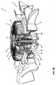
- Fig. 1B
- eine perspektivische, geschnittene Darstellung der Flüssigkeitsreibungskupplung gemäß
Fig. 1A , - Fig. 2A
- eine der
Fig. 1A entsprechende Darstellung der Flüssigkeitsreibungskupplung aus einer zweiten Ansichtsrichtung, - Fig. 2B
- eine der
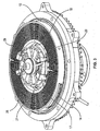
Fig. 1B entsprechende Darstellung der Flüssigkeitsreibungskupplung aus der Ansichtsrichtung gemäßFig. 2A , - Fig. 3
- eine perspektivische Draufsicht auf die Flüssigkeitsreibungskupplung ohne Gehäusedeckel,
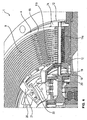
- Fig. 4
- eine der
Fig. 3 entsprechende Teildarstellung der Flüssigkeitsreibungskupplung, - Fig. 5
- eine der
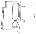
Fig. 4 entsprechende Teildarstellung eines anderen Bereiches der Flüssigkeitsreibungskupplung, - Fig. 6
- eine Detaildarstellung eines in
Fig. 5 dargestellten Ventilgliedes, - Fig. 7
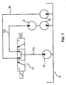
- eine erste Ausführungsform eines Hydraulikschaltplans für die erfindungsgemäße Flüssigkeitsreibungskupplung, und
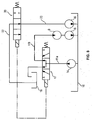
- Fig. 8
- eine der
Fig. 3 entsprechende Darstellung einer zweiten Ausführungsform des Hydraulikschaltplans für die erfindungsgemäße Flüssigkeitsreibungskupplung. - In
Fig. 1A ist eine Schnittdarstellung einer erfindungsgemäßen Flüssigkeitsreibungskupplung 1 dargestellt, die ein Gehäuse aufweist, das üblicherweise aus einem Gehäusekörper 2 und einem Deckel 3 aufgebaut ist. - Im Gehäuse 2, 3 ist eine Kupplungsscheibe 4 angeordnet, die gegenüber dem Gehäuse 2, 3 drehbar ist. Die gegenüber dem Gehäuse 2, 3 drehbare Kupplungsscheibe 4 ist hierbei drehfest an einem Ende 5 einer zentral innerhalb des Gehäuses 2, 3 gelagerten Welle 6 angeordnet. Am Gehäuse 2, 3 ist ein schematisch leicht vereinfacht dargestelltes antreibbares Wirkorgan 7 fixiert, das beispielsweise als Lüfterrad ausgebildet sein kann.
- Eine Arbeitskammer 9 ist zwischen dem Gehäuse 2, 3 und der Kupplungsscheibe 4 angeordnet, die, wie aus
Fig. 1A ersichtlich ist, Arbeitsspalte 15 aufweist, die aufgrund einer Scherwirkung auf die der Arbeitskammer 9 zugeführten Kupplungsflüssigkeit eine Drehmomentübertragung möglich machen. - Ferner ist eine Vorratskammer 10 für die genannte Kupplungsflüssigkeit vorgesehen, wobei ein Zuführkanal 11a, 11 b von der Vorratskammer 10 zur Arbeitskammer 9 führt und damit den Vorlauf bildet.
- Ferner ist erfindungsgemäß ein Rückpumpsystem bzw. eine Rückförderpumpe 16 vorgesehen, die zur Rückführung von Kupplungsflüssigkeit von der Arbeitskammer 9 zur Vorratskammer 10 dient. Diese Rückförderpumpe wird entweder von der entstehenden Fliehkraft gebildet, die zum Evakuieren der Arbeitskammer 9 Fluid zur Vorratskammer 10 nach außen pumpt. Alternativ ist es möglich, ein separates Bauteil in Form einer aktiven Rückförderpumpe vorzusehen, wie sie schematisch in dem Hydraulikdiagramm der
Fig. 7 und8 angedeutet ist, die über Scherkraft wirkt. - Die Flüssigkeitsreibungskupplung 1 weist ferner ein stationäres Kupplungsteil 13 auf, das gegenüber dem Gehäuse 2, 3 drehbar ist und vorzugsweise als Magnet, insbesondere Elektromagnet ausgebildet ist.
- Wie sich aus der Darstellung der
Fig. 1A ,1B ,2A und2B sowie 4 ergibt, ist ferner ein innenliegendes Reservoir 18 vorgesehen, das über den Zuführkanal 11 mit der Vorratskammer 10 verbunden ist. Hierbei ist das Ventil 17 in den Zuführkanal 11 a, 11 b zwischengeschaltet und die Vorratskammer 10 ist außenliegend angeordnet, wie sich dies im Einzelnen aus denFig. 1A bis 2B ergibt. - Ferner ist eine Rückströmsperre 19 vorgesehen, die zwischen dem Ventil 17 und dem Reservoir 18 angeordnet ist. Diese Rückströmsperre 19 kann beispielsweise ein Röhrchen sein, das über den Fluidspiegel hinaus in das Reservoir 18 hineinragt.
- Wie sich ferner aus den
Fig. 1A bis 2B sowie 4 und 5 ergibt, ist ein Rückleitventil 20 vorgesehen, das mit dem Ventil 17 wirkverbunden ist und einen Rücklaufkanal 23 zur Vorratskammer 10 öffnet bzw. schließt. - Das vorzugsweise als Mehrwegeventil ausgebildete Ventil 17 weist ein Ventilglied 24 auf, das eine Durchgangsbohrung 25 und eine Fluideinleitausnehmung 26 zum Einleiten von Fluid in die Arbeitskammer 9 aufweist, was sich vor allem aus
Fig. 5 und der Detaildarstellung derFig. 6 ergibt. - Ferner ist ein Aktuator 27 zur Betätigung des Ventils 17 und des Rückleitventils 20 vorgesehen. Vorzugsweise weist der Aktuator 27 einen relativ zur Welle 26 drehbaren Anker 28 und ein mit der Welle 6 drehbaren Fluxring 29 auf, der vom stationären Kupplungsteil in Form des Magneten 13 erregbar ist (s.
Fig. 3 ). - Der Aktuator 27 kann auch durch einen Bimetallstreifen (nicht dargestellt) anstelle des Ankers und des Magneten bewegt werden.
- Bei einer besonders bevorzugten Ausführungsform ist die Vorratskammer 10 auf der Sekundärseite der Flüssigkeitsreibungskupplung 1 und die innenliegende Kammer 18 auf der Primärseite der Flüssigkeitsreibungskupplung 1 vorgesehen.
- Schließlich weist gemäß
Fig. 7 bei einer alternativen Ausführungsform die Flüssigkeitsreibungskupplung 1 eine Rücklaufbohrung 30 zur Druckentlastung auf, die den Zuführkanal bzw. Zuführkanalabschnitt 11a über eine weitere (nicht dargestellte) Fluideinleitungsöffnung des Ventils 17 mit der Vorratskammer 10 verbindet. Bei dieser Ausführungsform ist kein inneres Volumen vorgesehen, so dass das Öl nicht über das innenliegende Reservoir zurückgefördert wird. Diese Ausführungsform der erfindungsgemäßen Flüssigkeitsreibungskupplung 1 kann bei kleineren Kupplungsbauformen, die kein inneres Volumen benötigen, verwendet werden, da bei diesen die Schleppmomente gering sind. - Neben der vorstehenden schriftlichen Offenbarung der Erfindung wird hiermit zur Ergänzung der Erfindungsoffenbarung explizit auf die zeichnerische Darstellung der Erfindung in den
Fig. 1 bis 4 verwiesen. -
- 1
- Flüssigkeitsreibungskupplung
- 2, 3
- Gehäuse (2: Gehäusekörper, 3: Deckel)
- 4
- Kupplungsscheibe
- 5
- Ende der Welle 6
- 6
- Welle
- 7
- Wirkorgan (z.B. Pumpenrad, Lüfterrad usw.)
- 8
- zweites Ende der Welle 6
- 9
- Arbeitskammer
- 10
- Vorratskammer
- 11a, 11b
- Zuführkanal
- 12
- Scherspalt
- 13
- stationäres Kupplungsteile (Magnet)
- 14
- Vorlaufpumpenelement
- 15
- Arbeitsspalte
- 16
- Rückförderpumpe
- 17
- Ventil
- 18
- innenliegendes Reservoir
- 19
- Rückströmsperre
- 20
- Rückleitventil
- 21
- Ventilarm
- 22
- Verbindungsbohrung
- 23
- Rücklaufkanal
- 24
- Ventilglied
- 25
- Durchgangsbohrung
- 26
- Fluideinleitausnehmung
- 27
- Aktuator
- 28
- Anker
- 29
- Fluxring
- 30
- Rücklaufbohrung
Claims (14)
- Flüssigkeitsreibungskupplung (1)- mit einem Gehäuse (2, 3), an dem ein Wirkorgan (7) angeordnet ist- mit einer Kupplungsscheibe (4),• die gegenüber dem Gehäuse (2, 3) drehbar ist, und• die an einem Ende (5) einer zentral innerhalb des Gehäuses (2, 3) gelagerten Welle (6) angeordnet ist,- mit einer Arbeitskammer (9) zwischen dem Gehäuse (2, 3) und der Kupplungsscheibe (4);- mit einer Vorratskammer (10) für Kupplungsflüssigkeit; und- mit einem Zuführkanal (11a, 11 b), der von der Vorratskammer (10) zur Arbeitskammer (9) führt, und in dem ein Ventil (17) angeordnet ist, gekennzeichnet- durch ein gegenüber dem Gehäuse (2, 3) drehbares Vorlaufpumpenelement (14),• das drehfest auf der Welle (6) angeordnet ist, und• das mit dem Gehäuse (2, 3) einen Scherspalt (12) definiert; und- wobei die Vorratskammer (10) außen liegend angeordnet ist.
- Flüssigkeitsreibungskupplung nach Anspruch 1, dadurch gekennzeichnet, dass ein stationäres Kupplungsteil (13) vorgesehen ist, gegenüber dem das Gehäuse (3) drehbar ist.
- Flüssigkeitsreibungskupplung nach Anspruch 1 oder 2; gekennzeichnet durch ein innenliegendes Reservoir (18), das über den Zuführkanal (11a, 11b) unter Zwischenschaltung des Ventils (17) mit der Vorratskammer (10) verbunden ist.
- Flüssigkeitsreibungskupplung nach Anspruch 3, gekennzeichnet durch eine Rückströmsperre (19), die zwischen dem Ventil (17) und dem Reservoir (18) angeordnet ist.
- Flüssigkeitsreibungskupplung nach einem der Ansprüche 1 bis 4, dadurch gekennzeichnet, dass das Ventil (17) ein Mehrwegeventil ist.
- Flüssigkeitsreibungskupplung nach einem der Ansprüche 1 bis 5, gekennzeichnet durch ein Rückleitventil (20), das mit dem Ventil (17) wirkverbunden ist und einen Rücklaufkanal (23) zur Vorratskammer (10) öffnet bzw. schließt.
- Flüssigkeitsreibungskupplung nach Anspruch 5, dadurch gekennzeichnet, dass das Mehrwegeventil (17) ein Ventilglied (24) aufweist, das eine Durchgangsbohrung (25) und eine Fluideinleitausnehmung (26) zum Einleiten von Fluid in die Arbeitskammer (9) aufweist.
- Flüssigkeitsreibungskupplung nach einem der Ansprüche 1 bis 7, gekennzeichnet durch eine Rückförderpumpe (16) zur Rückführung von Kupplungsflüssigkeit von der Arbeitskammer (9) zur Vorratskammer (10).
- Flüssigkeitsreibungskupplung nach einem der Ansprüche 1 bis 8, gekennzeichnet durch einen Aktuator (27) zur Betätigung des Ventils (17) und des Rückleitventils (20).
- Flüssigkeitsreibungskupplung nach Anspruch 9, dadurch gekennzeichnet, dass der Aktuator (27) einen relativ zur Welle (6) drehbaren Anker (28) und einen mit der Welle (6) drehbaren Fluxring (29) aufweist, der vom stationären Kupplungsteil (13) erregt wird.
- Flüssigkeitsreibungskupplung nach Anspruch 9, dadurch gekennzeichnet, dass der Aktuator (27) mittels einer Bimetallstreifenanordnung bewegbar ist.
- Flüssigkeitsreibungskupplung nach einem der Ansprüche 1 bis 11, dadurch gekennzeichnet, dass die Vorratskammer (10) vorzugsweise auf der Sekundärseite angeordnet ist.
- Flüssigkeitsreibungskupplung nach einem der Ansprüche 1 bis 12, dadurch gekennzeichnet, dass das innenliegende Reservoir (18) auf der Primärseite angeordnet ist.
- Flüssigkeitsreibungskupplung nach Anspruch 1, gekennzeichnet durch eine Rücklaufbohrung (30) zur Druckentlastung, die einen Zuführkanalabschnitt (11a) des Zuführkanals (11a, 11b) über eine weitere Fluideinleitungsöffnung des Ventils (17) mit der Vorratskammer (10) verbindet.
Priority Applications (5)
| Application Number | Priority Date | Filing Date | Title |
|---|---|---|---|
| EP12004767.5A EP2679849B1 (de) | 2012-06-26 | 2012-06-26 | Flüssigkeitsreibungskupplung |
| US14/410,614 US9328780B2 (en) | 2012-06-26 | 2013-06-24 | Fluid friction clutch |
| PCT/US2013/047238 WO2014004338A1 (en) | 2012-06-26 | 2013-06-24 | Fluid friction clutch |
| CN201380040047.4A CN104508312B (zh) | 2012-06-26 | 2013-06-24 | 流体摩擦式离合器 |
| IN415DEN2015 IN2015DN00415A (de) | 2012-06-26 | 2013-06-24 |
Applications Claiming Priority (1)
| Application Number | Priority Date | Filing Date | Title |
|---|---|---|---|
| EP12004767.5A EP2679849B1 (de) | 2012-06-26 | 2012-06-26 | Flüssigkeitsreibungskupplung |
Publications (2)
| Publication Number | Publication Date |
|---|---|
| EP2679849A1 EP2679849A1 (de) | 2014-01-01 |
| EP2679849B1 true EP2679849B1 (de) | 2016-09-07 |
Family
ID=46464986
Family Applications (1)
| Application Number | Title | Priority Date | Filing Date |
|---|---|---|---|
| EP12004767.5A Revoked EP2679849B1 (de) | 2012-06-26 | 2012-06-26 | Flüssigkeitsreibungskupplung |
Country Status (5)
| Country | Link |
|---|---|
| US (1) | US9328780B2 (de) |
| EP (1) | EP2679849B1 (de) |
| CN (1) | CN104508312B (de) |
| IN (1) | IN2015DN00415A (de) |
| WO (1) | WO2014004338A1 (de) |
Families Citing this family (5)
| Publication number | Priority date | Publication date | Assignee | Title |
|---|---|---|---|---|
| DE102015200930A1 (de) | 2015-01-21 | 2016-08-04 | Borgwarner Inc. | Flüssigkeitsreibungskupplung |
| US9470278B1 (en) * | 2015-11-10 | 2016-10-18 | Borgwarner Inc. | Apparatus employing shear forces to transmit energy having flow altering structures configured to increase heat rejection from a working fluid and related method |
| DE102017216696B4 (de) | 2017-09-21 | 2019-05-23 | Borgwarner Ludwigsburg Gmbh | Flüssigkeitsreibungskupplung |
| WO2019213359A1 (en) | 2018-05-02 | 2019-11-07 | Horton, Inc. | Energy harvesting clutch control assembly, valve assembly, and electrically actuated clutch |
| CN115516224B (zh) * | 2020-05-14 | 2025-10-17 | 霍顿公司 | 用于粘滞摩擦离合器的阀控制系统 |
Citations (8)
| Publication number | Priority date | Publication date | Assignee | Title |
|---|---|---|---|---|
| US5499706A (en) | 1993-12-30 | 1996-03-19 | Unisia Jecs Corporation | Viscous fluid clutch with auxiliary reservoir |
| DE19548065A1 (de) | 1995-12-21 | 1997-06-26 | Fichtel & Sachs Ag | Visko-Lüfterkupplung mit fliehkraftbedingt befüllbarer Vorratskammer |
| EP0936371A1 (de) | 1998-02-16 | 1999-08-18 | Eaton Corporation | Wassergekühlter Flüssigkeitsreibungsantrieb eines Ventilators |
| US6026943A (en) | 1999-04-16 | 2000-02-22 | Eaton Corporation | Segmented reservoir for viscous clutches |
| DE10338432A1 (de) | 2002-08-23 | 2004-03-04 | Behr Gmbh & Co. Kg | Flüssigkeitsreibkupplung |
| EP1566526A2 (de) | 2004-02-23 | 2005-08-24 | Behr GmbH & Co. KG | Regelbarer Antrieb für ein Kraftfahrzeug |
| WO2007016314A1 (en) | 2005-07-29 | 2007-02-08 | Horton, Inc. | Viscous clutch |
| EP1731787B1 (de) | 2005-06-09 | 2008-08-13 | BorgWarner Inc. | Flüssigkeitsreibungskupplung |
Family Cites Families (11)
| Publication number | Priority date | Publication date | Assignee | Title |
|---|---|---|---|---|
| US4086987A (en) | 1976-09-27 | 1978-05-02 | General Motors Corporation | Viscous fluid clutch |
| US4278157A (en) | 1979-02-16 | 1981-07-14 | King Palmer F | Fluid clutch |
| DE3445664A1 (de) * | 1984-12-14 | 1986-06-26 | Daimler-Benz Ag, 7000 Stuttgart | Fluessigkeitsreibungskupplung mit vorratskammer in der primaerscheibe |
| US4828088A (en) * | 1987-05-18 | 1989-05-09 | Eaton Corporation | Closed loop pulse modulated viscous fan control |
| DE19742823B4 (de) * | 1997-09-27 | 2004-05-19 | Behr Gmbh & Co. | Flüssigkeitsreibungskupplung |
| US6125981A (en) * | 1998-06-17 | 2000-10-03 | Usui Kokusai Sangyo Kaisha Limited | Temperature sensitive fluid type fan coupling apparatus |
| JP2002130332A (ja) | 2000-10-30 | 2002-05-09 | Isuzu Motors Ltd | 流体クラッチ |
| CN102472334B (zh) * | 2009-07-09 | 2014-10-01 | 博格华纳公司 | 流体离合器装置 |
| DE112010002888T5 (de) * | 2009-07-10 | 2012-06-14 | Borgwarner Inc. | Fluid-Speicherkammer |
| ATE556241T1 (de) * | 2009-08-12 | 2012-05-15 | Borgwarner Inc | Flüssigkeitsreibungskupplung |
| EP2487380B1 (de) * | 2011-02-14 | 2013-05-01 | BorgWarner, Inc. | Flüssigkeitsreibungkupplung |
-
2012
- 2012-06-26 EP EP12004767.5A patent/EP2679849B1/de not_active Revoked
-
2013
- 2013-06-24 CN CN201380040047.4A patent/CN104508312B/zh not_active Expired - Fee Related
- 2013-06-24 US US14/410,614 patent/US9328780B2/en active Active
- 2013-06-24 IN IN415DEN2015 patent/IN2015DN00415A/en unknown
- 2013-06-24 WO PCT/US2013/047238 patent/WO2014004338A1/en not_active Ceased
Patent Citations (8)
| Publication number | Priority date | Publication date | Assignee | Title |
|---|---|---|---|---|
| US5499706A (en) | 1993-12-30 | 1996-03-19 | Unisia Jecs Corporation | Viscous fluid clutch with auxiliary reservoir |
| DE19548065A1 (de) | 1995-12-21 | 1997-06-26 | Fichtel & Sachs Ag | Visko-Lüfterkupplung mit fliehkraftbedingt befüllbarer Vorratskammer |
| EP0936371A1 (de) | 1998-02-16 | 1999-08-18 | Eaton Corporation | Wassergekühlter Flüssigkeitsreibungsantrieb eines Ventilators |
| US6026943A (en) | 1999-04-16 | 2000-02-22 | Eaton Corporation | Segmented reservoir for viscous clutches |
| DE10338432A1 (de) | 2002-08-23 | 2004-03-04 | Behr Gmbh & Co. Kg | Flüssigkeitsreibkupplung |
| EP1566526A2 (de) | 2004-02-23 | 2005-08-24 | Behr GmbH & Co. KG | Regelbarer Antrieb für ein Kraftfahrzeug |
| EP1731787B1 (de) | 2005-06-09 | 2008-08-13 | BorgWarner Inc. | Flüssigkeitsreibungskupplung |
| WO2007016314A1 (en) | 2005-07-29 | 2007-02-08 | Horton, Inc. | Viscous clutch |
Also Published As
| Publication number | Publication date |
|---|---|
| CN104508312A (zh) | 2015-04-08 |
| US20150144452A1 (en) | 2015-05-28 |
| WO2014004338A1 (en) | 2014-01-03 |
| US9328780B2 (en) | 2016-05-03 |
| EP2679849A1 (de) | 2014-01-01 |
| IN2015DN00415A (de) | 2015-06-19 |
| CN104508312B (zh) | 2017-03-08 |
Similar Documents
| Publication | Publication Date | Title |
|---|---|---|
| EP2284414B1 (de) | Flüssigkeitsreibungskupplung | |
| EP2679849B1 (de) | Flüssigkeitsreibungskupplung | |
| EP2487380B1 (de) | Flüssigkeitsreibungkupplung | |
| EP2336546B1 (de) | Kraftstoff-Hochdruckpumpe | |
| DE102010039918B4 (de) | Druckregelventil in Schieberbauweise mit verbessertem Dämpfungsverhalten | |
| EP1566526B1 (de) | Kühlmittelpumpe für ein Kraftfahrzeug, mit regelbarem Antrieb | |
| DE102013018205B3 (de) | Regelbare Kühlmittelpumpe | |
| DE10206927B4 (de) | Hydraulisch dämpfendes Lager | |
| DE19742823A1 (de) | Flüssigkeitsreibungskupplung | |
| EP1454075B1 (de) | Elektromagnetisch angesteuerte flüssigkeitsreibungskupplung | |
| EP3077712B1 (de) | Magentventil | |
| EP2213921B1 (de) | Druckregelventil | |
| DE102009057070A1 (de) | Kolbenmaschine zum Einsatz als Vakuumpumpe für medizinische Zwecke | |
| DE102015200930A1 (de) | Flüssigkeitsreibungskupplung | |
| DE3716190A1 (de) | Schlupfregelsystem fuer die trennkupplung einer stroemungskupplung | |
| DE102010064114B4 (de) | Pumpe mit einer Drossel | |
| EP2626584B1 (de) | Flüssigkeitsreibungskupplung | |
| DE102015205340A1 (de) | Flüssigkeitsreibungskupplung | |
| DE2740845C2 (de) | ||
| DE102015203064A1 (de) | Flüssigkeitsreibungskupplung | |
| EP2679850B1 (de) | Flüssigkeitsreibungskupplung | |
| DE102006022472B3 (de) | Hydrostatische Kupplungsanordnung mit Zahnringmaschine | |
| DE102014006503A1 (de) | Membranpumpe | |
| DE102011013569A1 (de) | Druckspeicher mit Solenoidventil | |
| DE102017216696B4 (de) | Flüssigkeitsreibungskupplung |
Legal Events
| Date | Code | Title | Description |
|---|---|---|---|
| PUAI | Public reference made under article 153(3) epc to a published international application that has entered the european phase |
Free format text: ORIGINAL CODE: 0009012 |
|
| AK | Designated contracting states |
Kind code of ref document: A1 Designated state(s): AL AT BE BG CH CY CZ DE DK EE ES FI FR GB GR HR HU IE IS IT LI LT LU LV MC MK MT NL NO PL PT RO RS SE SI SK SM TR |
|
| AX | Request for extension of the european patent |
Extension state: BA ME |
|
| 17P | Request for examination filed |
Effective date: 20140701 |
|
| RBV | Designated contracting states (corrected) |
Designated state(s): AL AT BE BG CH CY CZ DE DK EE ES FI FR GB GR HR HU IE IS IT LI LT LU LV MC MK MT NL NO PL PT RO RS SE SI SK SM TR |
|
| GRAP | Despatch of communication of intention to grant a patent |
Free format text: ORIGINAL CODE: EPIDOSNIGR1 |
|
| INTG | Intention to grant announced |
Effective date: 20160428 |
|
| GRAS | Grant fee paid |
Free format text: ORIGINAL CODE: EPIDOSNIGR3 |
|
| GRAA | (expected) grant |
Free format text: ORIGINAL CODE: 0009210 |
|
| AK | Designated contracting states |
Kind code of ref document: B1 Designated state(s): AL AT BE BG CH CY CZ DE DK EE ES FI FR GB GR HR HU IE IS IT LI LT LU LV MC MK MT NL NO PL PT RO RS SE SI SK SM TR |
|
| REG | Reference to a national code |
Ref country code: GB Ref legal event code: FG4D Free format text: NOT ENGLISH |
|
| REG | Reference to a national code |
Ref country code: CH Ref legal event code: EP |
|
| REG | Reference to a national code |
Ref country code: IE Ref legal event code: FG4D Free format text: LANGUAGE OF EP DOCUMENT: GERMAN |
|
| REG | Reference to a national code |
Ref country code: AT Ref legal event code: REF Ref document number: 827170 Country of ref document: AT Kind code of ref document: T Effective date: 20161015 |
|
| REG | Reference to a national code |
Ref country code: DE Ref legal event code: R096 Ref document number: 502012008158 Country of ref document: DE |
|
| REG | Reference to a national code |
Ref country code: LT Ref legal event code: MG4D |
|
| REG | Reference to a national code |
Ref country code: NL Ref legal event code: MP Effective date: 20160907 |
|
| PG25 | Lapsed in a contracting state [announced via postgrant information from national office to epo] |
Ref country code: HR Free format text: LAPSE BECAUSE OF FAILURE TO SUBMIT A TRANSLATION OF THE DESCRIPTION OR TO PAY THE FEE WITHIN THE PRESCRIBED TIME-LIMIT Effective date: 20160907 Ref country code: FI Free format text: LAPSE BECAUSE OF FAILURE TO SUBMIT A TRANSLATION OF THE DESCRIPTION OR TO PAY THE FEE WITHIN THE PRESCRIBED TIME-LIMIT Effective date: 20160907 Ref country code: LT Free format text: LAPSE BECAUSE OF FAILURE TO SUBMIT A TRANSLATION OF THE DESCRIPTION OR TO PAY THE FEE WITHIN THE PRESCRIBED TIME-LIMIT Effective date: 20160907 Ref country code: RS Free format text: LAPSE BECAUSE OF FAILURE TO SUBMIT A TRANSLATION OF THE DESCRIPTION OR TO PAY THE FEE WITHIN THE PRESCRIBED TIME-LIMIT Effective date: 20160907 Ref country code: NO Free format text: LAPSE BECAUSE OF FAILURE TO SUBMIT A TRANSLATION OF THE DESCRIPTION OR TO PAY THE FEE WITHIN THE PRESCRIBED TIME-LIMIT Effective date: 20161207 |
|
| PG25 | Lapsed in a contracting state [announced via postgrant information from national office to epo] |
Ref country code: NL Free format text: LAPSE BECAUSE OF FAILURE TO SUBMIT A TRANSLATION OF THE DESCRIPTION OR TO PAY THE FEE WITHIN THE PRESCRIBED TIME-LIMIT Effective date: 20160907 Ref country code: GR Free format text: LAPSE BECAUSE OF FAILURE TO SUBMIT A TRANSLATION OF THE DESCRIPTION OR TO PAY THE FEE WITHIN THE PRESCRIBED TIME-LIMIT Effective date: 20161208 Ref country code: SE Free format text: LAPSE BECAUSE OF FAILURE TO SUBMIT A TRANSLATION OF THE DESCRIPTION OR TO PAY THE FEE WITHIN THE PRESCRIBED TIME-LIMIT Effective date: 20160907 Ref country code: LV Free format text: LAPSE BECAUSE OF FAILURE TO SUBMIT A TRANSLATION OF THE DESCRIPTION OR TO PAY THE FEE WITHIN THE PRESCRIBED TIME-LIMIT Effective date: 20160907 Ref country code: ES Free format text: LAPSE BECAUSE OF FAILURE TO SUBMIT A TRANSLATION OF THE DESCRIPTION OR TO PAY THE FEE WITHIN THE PRESCRIBED TIME-LIMIT Effective date: 20160907 |
|
| PG25 | Lapsed in a contracting state [announced via postgrant information from national office to epo] |
Ref country code: RO Free format text: LAPSE BECAUSE OF FAILURE TO SUBMIT A TRANSLATION OF THE DESCRIPTION OR TO PAY THE FEE WITHIN THE PRESCRIBED TIME-LIMIT Effective date: 20160907 Ref country code: EE Free format text: LAPSE BECAUSE OF FAILURE TO SUBMIT A TRANSLATION OF THE DESCRIPTION OR TO PAY THE FEE WITHIN THE PRESCRIBED TIME-LIMIT Effective date: 20160907 |
|
| PG25 | Lapsed in a contracting state [announced via postgrant information from national office to epo] |
Ref country code: PT Free format text: LAPSE BECAUSE OF FAILURE TO SUBMIT A TRANSLATION OF THE DESCRIPTION OR TO PAY THE FEE WITHIN THE PRESCRIBED TIME-LIMIT Effective date: 20170109 Ref country code: BG Free format text: LAPSE BECAUSE OF FAILURE TO SUBMIT A TRANSLATION OF THE DESCRIPTION OR TO PAY THE FEE WITHIN THE PRESCRIBED TIME-LIMIT Effective date: 20161207 Ref country code: SK Free format text: LAPSE BECAUSE OF FAILURE TO SUBMIT A TRANSLATION OF THE DESCRIPTION OR TO PAY THE FEE WITHIN THE PRESCRIBED TIME-LIMIT Effective date: 20160907 Ref country code: SM Free format text: LAPSE BECAUSE OF FAILURE TO SUBMIT A TRANSLATION OF THE DESCRIPTION OR TO PAY THE FEE WITHIN THE PRESCRIBED TIME-LIMIT Effective date: 20160907 Ref country code: PL Free format text: LAPSE BECAUSE OF FAILURE TO SUBMIT A TRANSLATION OF THE DESCRIPTION OR TO PAY THE FEE WITHIN THE PRESCRIBED TIME-LIMIT Effective date: 20160907 Ref country code: IS Free format text: LAPSE BECAUSE OF FAILURE TO SUBMIT A TRANSLATION OF THE DESCRIPTION OR TO PAY THE FEE WITHIN THE PRESCRIBED TIME-LIMIT Effective date: 20170107 Ref country code: CZ Free format text: LAPSE BECAUSE OF FAILURE TO SUBMIT A TRANSLATION OF THE DESCRIPTION OR TO PAY THE FEE WITHIN THE PRESCRIBED TIME-LIMIT Effective date: 20160907 |
|
| REG | Reference to a national code |
Ref country code: DE Ref legal event code: R026 Ref document number: 502012008158 Country of ref document: DE |
|
| PLBI | Opposition filed |
Free format text: ORIGINAL CODE: 0009260 |
|
| PG25 | Lapsed in a contracting state [announced via postgrant information from national office to epo] |
Ref country code: IT Free format text: LAPSE BECAUSE OF FAILURE TO SUBMIT A TRANSLATION OF THE DESCRIPTION OR TO PAY THE FEE WITHIN THE PRESCRIBED TIME-LIMIT Effective date: 20160907 |
|
| 26 | Opposition filed |
Opponent name: MAHLE INTERNATIONAL GMBH Effective date: 20170602 |
|
| PLAX | Notice of opposition and request to file observation + time limit sent |
Free format text: ORIGINAL CODE: EPIDOSNOBS2 |
|
| PG25 | Lapsed in a contracting state [announced via postgrant information from national office to epo] |
Ref country code: DK Free format text: LAPSE BECAUSE OF FAILURE TO SUBMIT A TRANSLATION OF THE DESCRIPTION OR TO PAY THE FEE WITHIN THE PRESCRIBED TIME-LIMIT Effective date: 20160907 |
|
| PG25 | Lapsed in a contracting state [announced via postgrant information from national office to epo] |
Ref country code: SI Free format text: LAPSE BECAUSE OF FAILURE TO SUBMIT A TRANSLATION OF THE DESCRIPTION OR TO PAY THE FEE WITHIN THE PRESCRIBED TIME-LIMIT Effective date: 20160907 |
|
| PG25 | Lapsed in a contracting state [announced via postgrant information from national office to epo] |
Ref country code: MC Free format text: LAPSE BECAUSE OF FAILURE TO SUBMIT A TRANSLATION OF THE DESCRIPTION OR TO PAY THE FEE WITHIN THE PRESCRIBED TIME-LIMIT Effective date: 20160907 |
|
| REG | Reference to a national code |
Ref country code: CH Ref legal event code: PL |
|
| GBPC | Gb: european patent ceased through non-payment of renewal fee |
Effective date: 20170626 |
|
| REG | Reference to a national code |
Ref country code: IE Ref legal event code: MM4A |
|
| REG | Reference to a national code |
Ref country code: FR Ref legal event code: ST Effective date: 20180228 |
|
| PG25 | Lapsed in a contracting state [announced via postgrant information from national office to epo] |
Ref country code: LU Free format text: LAPSE BECAUSE OF NON-PAYMENT OF DUE FEES Effective date: 20170626 Ref country code: IE Free format text: LAPSE BECAUSE OF NON-PAYMENT OF DUE FEES Effective date: 20170626 Ref country code: GB Free format text: LAPSE BECAUSE OF NON-PAYMENT OF DUE FEES Effective date: 20170626 Ref country code: CH Free format text: LAPSE BECAUSE OF NON-PAYMENT OF DUE FEES Effective date: 20170630 Ref country code: LI Free format text: LAPSE BECAUSE OF NON-PAYMENT OF DUE FEES Effective date: 20170630 |
|
| PG25 | Lapsed in a contracting state [announced via postgrant information from national office to epo] |
Ref country code: FR Free format text: LAPSE BECAUSE OF NON-PAYMENT OF DUE FEES Effective date: 20170630 |
|
| REG | Reference to a national code |
Ref country code: BE Ref legal event code: MM Effective date: 20170630 |
|
| PGFP | Annual fee paid to national office [announced via postgrant information from national office to epo] |
Ref country code: DE Payment date: 20180608 Year of fee payment: 7 |
|
| REG | Reference to a national code |
Ref country code: AT Ref legal event code: MM01 Ref document number: 827170 Country of ref document: AT Kind code of ref document: T Effective date: 20170626 |
|
| PG25 | Lapsed in a contracting state [announced via postgrant information from national office to epo] |
Ref country code: BE Free format text: LAPSE BECAUSE OF NON-PAYMENT OF DUE FEES Effective date: 20170630 |
|
| PG25 | Lapsed in a contracting state [announced via postgrant information from national office to epo] |
Ref country code: MT Free format text: LAPSE BECAUSE OF FAILURE TO SUBMIT A TRANSLATION OF THE DESCRIPTION OR TO PAY THE FEE WITHIN THE PRESCRIBED TIME-LIMIT Effective date: 20160907 |
|
| PG25 | Lapsed in a contracting state [announced via postgrant information from national office to epo] |
Ref country code: AL Free format text: LAPSE BECAUSE OF FAILURE TO SUBMIT A TRANSLATION OF THE DESCRIPTION OR TO PAY THE FEE WITHIN THE PRESCRIBED TIME-LIMIT Effective date: 20160907 |
|
| RDAF | Communication despatched that patent is revoked |
Free format text: ORIGINAL CODE: EPIDOSNREV1 |
|
| STAA | Information on the status of an ep patent application or granted ep patent |
Free format text: STATUS: THE PATENT HAS BEEN GRANTED |
|
| PG25 | Lapsed in a contracting state [announced via postgrant information from national office to epo] |
Ref country code: AT Free format text: LAPSE BECAUSE OF NON-PAYMENT OF DUE FEES Effective date: 20170626 |
|
| REG | Reference to a national code |
Ref country code: DE Ref legal event code: R064 Ref document number: 502012008158 Country of ref document: DE Ref country code: DE Ref legal event code: R103 Ref document number: 502012008158 Country of ref document: DE |
|
| RDAG | Patent revoked |
Free format text: ORIGINAL CODE: 0009271 |
|
| STAA | Information on the status of an ep patent application or granted ep patent |
Free format text: STATUS: PATENT REVOKED |
|
| 27W | Patent revoked |
Effective date: 20181206 |
|
| REG | Reference to a national code |
Ref country code: AT Ref legal event code: MA03 Ref document number: 827170 Country of ref document: AT Kind code of ref document: T Effective date: 20181206 |
|
| PG25 | Lapsed in a contracting state [announced via postgrant information from national office to epo] |
Ref country code: MK Free format text: LAPSE BECAUSE OF FAILURE TO SUBMIT A TRANSLATION OF THE DESCRIPTION OR TO PAY THE FEE WITHIN THE PRESCRIBED TIME-LIMIT Effective date: 20160907 |
|
| PG25 | Lapsed in a contracting state [announced via postgrant information from national office to epo] |
Ref country code: CY Free format text: LAPSE BECAUSE OF FAILURE TO SUBMIT A TRANSLATION OF THE DESCRIPTION OR TO PAY THE FEE WITHIN THE PRESCRIBED TIME-LIMIT Effective date: 20160907 |
|
| PG25 | Lapsed in a contracting state [announced via postgrant information from national office to epo] |
Ref country code: TR Free format text: LAPSE BECAUSE OF FAILURE TO SUBMIT A TRANSLATION OF THE DESCRIPTION OR TO PAY THE FEE WITHIN THE PRESCRIBED TIME-LIMIT Effective date: 20160907 |