EP2679755A2 - Tür- oder Trennsystem - Google Patents
Tür- oder Trennsystem Download PDFInfo
- Publication number
- EP2679755A2 EP2679755A2 EP13002748.5A EP13002748A EP2679755A2 EP 2679755 A2 EP2679755 A2 EP 2679755A2 EP 13002748 A EP13002748 A EP 13002748A EP 2679755 A2 EP2679755 A2 EP 2679755A2
- Authority
- EP
- European Patent Office
- Prior art keywords
- door
- partition
- light beam
- partition wall
- wall
- Prior art date
- Legal status (The legal status is an assumption and is not a legal conclusion. Google has not performed a legal analysis and makes no representation as to the accuracy of the status listed.)
- Granted
Links
- 238000000926 separation method Methods 0.000 title claims abstract 3
- 238000005192 partition Methods 0.000 claims abstract description 80
- 230000004888 barrier function Effects 0.000 claims abstract description 15
- 238000007789 sealing Methods 0.000 claims description 25
- 239000000463 material Substances 0.000 claims description 2
- 230000000903 blocking effect Effects 0.000 claims 1
- 238000012544 monitoring process Methods 0.000 description 5
- 238000004519 manufacturing process Methods 0.000 description 3
- 238000001514 detection method Methods 0.000 description 2
- 229910000831 Steel Inorganic materials 0.000 description 1
- 238000010276 construction Methods 0.000 description 1
- 238000011161 development Methods 0.000 description 1
- 230000018109 developmental process Effects 0.000 description 1
- 239000010959 steel Substances 0.000 description 1
Images

Classifications
-
- E—FIXED CONSTRUCTIONS
- E05—LOCKS; KEYS; WINDOW OR DOOR FITTINGS; SAFES
- E05F—DEVICES FOR MOVING WINGS INTO OPEN OR CLOSED POSITION; CHECKS FOR WINGS; WING FITTINGS NOT OTHERWISE PROVIDED FOR, CONCERNED WITH THE FUNCTIONING OF THE WING
- E05F15/00—Power-operated mechanisms for wings
- E05F15/60—Power-operated mechanisms for wings using electrical actuators
- E05F15/603—Power-operated mechanisms for wings using electrical actuators using rotary electromotors
- E05F15/608—Power-operated mechanisms for wings using electrical actuators using rotary electromotors for revolving wings
-
- E—FIXED CONSTRUCTIONS
- E05—LOCKS; KEYS; WINDOW OR DOOR FITTINGS; SAFES
- E05F—DEVICES FOR MOVING WINGS INTO OPEN OR CLOSED POSITION; CHECKS FOR WINGS; WING FITTINGS NOT OTHERWISE PROVIDED FOR, CONCERNED WITH THE FUNCTIONING OF THE WING
- E05F15/00—Power-operated mechanisms for wings
- E05F15/40—Safety devices, e.g. detection of obstructions or end positions
- E05F15/42—Detection using safety edges
- E05F15/43—Detection using safety edges responsive to disruption of energy beams, e.g. light or sound
-
- E—FIXED CONSTRUCTIONS
- E05—LOCKS; KEYS; WINDOW OR DOOR FITTINGS; SAFES
- E05F—DEVICES FOR MOVING WINGS INTO OPEN OR CLOSED POSITION; CHECKS FOR WINGS; WING FITTINGS NOT OTHERWISE PROVIDED FOR, CONCERNED WITH THE FUNCTIONING OF THE WING
- E05F15/00—Power-operated mechanisms for wings
- E05F15/40—Safety devices, e.g. detection of obstructions or end positions
- E05F15/42—Detection using safety edges
- E05F15/43—Detection using safety edges responsive to disruption of energy beams, e.g. light or sound
- E05F2015/434—Detection using safety edges responsive to disruption of energy beams, e.g. light or sound with cameras or optical sensors
- E05F2015/435—Detection using safety edges responsive to disruption of energy beams, e.g. light or sound with cameras or optical sensors by interruption of the beam
-
- E—FIXED CONSTRUCTIONS
- E05—LOCKS; KEYS; WINDOW OR DOOR FITTINGS; SAFES
- E05Y—INDEXING SCHEME ASSOCIATED WITH SUBCLASSES E05D AND E05F, RELATING TO CONSTRUCTION ELEMENTS, ELECTRIC CONTROL, POWER SUPPLY, POWER SIGNAL OR TRANSMISSION, USER INTERFACES, MOUNTING OR COUPLING, DETAILS, ACCESSORIES, AUXILIARY OPERATIONS NOT OTHERWISE PROVIDED FOR, APPLICATION THEREOF
- E05Y2900/00—Application of doors, windows, wings or fittings thereof
- E05Y2900/10—Application of doors, windows, wings or fittings thereof for buildings or parts thereof
- E05Y2900/13—Type of wing
- E05Y2900/132—Doors
Definitions
- the present invention relates to a door or partition system according to the preamble of claim 1 with a light barrier for monitoring.
- the door or partition system is designed as a revolving door, sliding door, swing door or room dividing wall.
- FIG. 6 shows as an example a top view of a revolving door 100 according to the prior art.
- a dividing wall 103 divides the revolving door into a first chamber 111 and a second chamber 112.
- the dividing wall 103 rotates in the direction of rotation 104.
- the dividing wall 103 rotates, there is a portion of the dividing wall 103 in each chamber 111, 112 moves the user, and a share leading the user. It is important that the proportion of the partition wall 103 moving towards the user is monitored so that, for example, no pinching of feet or fingers between the partition wall 103 and the floor is possible.
- the monitoring takes place in the first chamber 111 with a first light beam 105 and in the second chamber 112 with a second light beam 106.
- the entire width of the partition 103 is monitored, so that the leading parts of the user Partition 103 are monitored.
- the unnecessary securing areas 107 mean that upon detection of an object in these areas, the revolving door 100 stops unnecessarily.
- a door or partition system comprising at least one movable partition member for locking and releasing a passage, a drive for actuating the separating element, and a light barrier with a horizontal light steel for driving the drive, wherein the light beam passes under the partition member
- the separating element is a partition wall in a revolving door, a sliding door leaf, a hinged door leaf and / or a room partition wall element of a room partition.
- the light beam according to the invention does not have to be absolutely horizontal. It is crucial that the area between the lower edge of the separating element and the floor is monitored. A "ray of light” is also a bundle of multiple rays of light to understand.
- the door or partition system is designed as a revolving door.
- the revolving door comprises at least one rotatable partition dividing the revolving door into a first and a second chamber.
- the first and second chambers may be persons at the same time.
- the one chamber serves to leave the building, the second chamber also serves to enter the building.
- the partition is set in rotation.
- the drive is monitored with the horizontal light beam. When this light beam is interrupted, the speed of the drive is stopped or changed the partition.
- the light beam passes under the dividing wall from the first chamber into the second chamber.
- only one light barrier with only one light beam is necessary for monitoring both chambers.
- the manufacturing and assembly costs are reduced and at the same time only the necessary areas are monitored
- the light beam passes through the center of the revolving door.
- the light beam extends approximately through the axis of rotation of the partition.
- the first half of the light beam can be used to monitor the first chamber.
- the second half of the light beam is used to monitor the second chamber.
- the light beam should be as close as possible to the dividing wall. Therefore, the angle between the light beam and the partition wall is preferably set to a constant value between 1 ° and 25 °.
- At the lower end of the partition is preferably at least one sealing element for sealing the partition wall relative to the ground.
- sealing elements are preferably formed as brush seals. So that the light beam can be carried out from the first chamber into the second chamber, the sealing element is recessed at one location, in particular at the center of the revolving door. Of course, a plurality of sealing elements can be used to form the recess, which are spaced to carry out the light beam.
- Part of the partition wall may be a sliding door or a swing door. This sliding or swing door can be used to walk around a building without rotating the partition.
- the sliding door or swing door integrated in the revolving door comprises at least a first and a second door leaf.
- a first sealing element is arranged at the bottom of the first door leaf.
- a second sealing element is arranged at the bottom of the second door leaf.
- the two sealing elements are preferably designed as brush seals.
- the two door leaves and thus also the two sealing elements preferably meet in the middle of the revolving door.
- the sealing elements in the center of the revolving door are spaced from each other and / or offset from each other. Offset to each other means that the two sealing elements are not aligned with each other.
- the revolving door can preferably be a showcase.
- a showcase is formed by another wall, which is angled to the partition.
- the showcase describes a dead space inside the revolving door, which rotates together with the partition, but can not be entered by the user.
- the light barrier is particularly preferably mounted on the other wall, which is used to form the showcase.
- the floor facing the surface of the partition with a non-reflective material, preferably dark-colored frosted formed.
- the revolving door described above is inexpensive to manufacture due to the only one light barrier. There are no losses in terms of safety, as the collision-prone area of the partition is still monitored by sensors.
- the invention can also be used in other door systems, not only revolving doors. Furthermore, the inventive idea can also be used in motor-driven space partitions.
- the decisive factor is that a light beam is always led under the door or partition walls (in general: separating element). For sliding doors, swing doors and room partitions, there is the advantage that all electronics of the light barrier can be installed in the frame. Thus, it requires no wiring of the separating element.
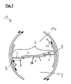
- Fig. 1 shows a revolving door 1 in plan view.
- the revolving door 1 comprises a partition wall 3 (also: separating element), which is rotated about an axis of rotation 10 by means of a drive, not shown.
- the partition 3 divides the revolving door into a first chamber 11 and a second chamber 12. In both chambers 11, 12 may be persons at the same time.
- a curved wall 7 is arranged in each case. The two curved walls 7 rotate together with the partition wall 3.
- the partition wall 3 is composed of two connected to the curved walls 7 walls 2 and a sliding door 4.
- the sliding door 4 includes a first door 5 and a second door 6.
- the two doors 5, 6 meet at the axis of rotation 10th
- the partition 3 is driven in the direction of rotation 21.
- the revolving door 1 can be committed via the sliding door 4.
- the light barrier 8 generates a light beam 9.
- the light beam 9 is for monitoring in the first chamber 11 and in the second chamber 12th
- the light beam 9 passes under the partition 3, in particular under the sliding door 4, and thus extends through both chambers 11, 12.
- the light beam 9 is as close as possible to the partition wall.
- the light beam 9 is necessary for monitoring both chambers 11, 12. Furthermore, the light beam is arranged so that only the relevant parts of the partition wall 3 are monitored.
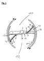
- Fig. 2 shows a second embodiment of the revolving door 1.
- the revolving door 1 in the second embodiment comprises two further walls 20.
- the two other walls 20 are angled relative to the partition wall 3 and against the walls 2. This creates between the wall 2, the other wall 20 and the curved wall 7 two showcases 13.
- On the other walls 20 are safety strips 14 for detecting an approaching object.
- the second embodiment shows that the light barrier 8 is preferably fastened to one of the further walls 20.
- Fig. 3 shows a third embodiment of the revolving door 1.
- two showcases 13 are formed by two further walls 20.
- the third embodiment shows an embodiment of the two door leaves 5, 6 as a swing door 15.
- the two door leaves 5, 6 are pivoted about an axis parallel to the axis of rotation 10.
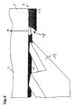
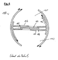
- Fig. 4 shows a detail of the revolving door 1 for the first three embodiments. Shown is the partition 3, in particular the first and second Door leaf 5, 6, approximately at the axis of rotation 10. At the lower edge of the first door leaf 5, a first sealing member 16 is arranged to seal against the ground. At the lower edge of the second door leaf 6, a second sealing element 17 is also arranged to seal against the ground.
- the two sealing elements 16, 17 are formed as brush seals. Due to the rotation of the partition wall 3 in the direction of rotation 21, the brushes of the sealing elements 16, 17 are in different directions.
- the two sealing elements 16, 17 are offset from one another or spaced from each other, so that the light beam 9 can be transferred approximately at the axis of rotation 10 of the one chamber into the other chamber 11, 12.
- the representation in Fig. 4 shows an offset and a spacing 18 of the sealing elements 16, 17.
- a standard specimen 19 is shown.
- This test piece 19 simulates the hand or foot of a user.
- the light beam 9 is interrupted by the test specimen 19. This causes the stopping or braking of the rotary movement of the partition wall 3.
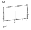
- Fig. 5 shows the construction of the door or partition system as a sliding door 30 according to the fourth embodiment.
- the sliding door 30 comprises two sliding door leaves 32 (also: separating elements), which are received in a frame 31.
- the sliding door leaves 32 are slightly spaced from the floor, so that the light beam 9 can pass under the sliding door wings 32 therethrough. All components for generating the light beam 9 are installed in the frame 31.
Landscapes
- Power-Operated Mechanisms For Wings (AREA)
- Extensible Doors And Revolving Doors (AREA)
Abstract
Description
- Vorliegende Erfindung betrifft ein Tür- oder Trennsystem gemäß dem Oberbegriff des Anspruchs 1 mit einer Lichtschranke zur Überwachung. Das Tür- oder Trennsystem ist ausgebildet als Karusselltür, Schiebetür, Drehflügeltür oder Raumtrennwand.
- Angetriebene Trennelemente von Tür- oder Trennsystemen werden zum Schutz des Benutzers mit Lichtschranken überwacht.
Fig. 6 zeigt als Beispiel eine Draufsicht auf eine Karusselltür 100 nach dem Stand der Technik. Eine Trennwand 103 unterteilt die Karusselltür in eine erste Kammer 111 und eine zweite Kammer 112. Mittels eines Antriebes rotiert die Trennwand 103 in Drehrichtung 104. Bei Rotation der Trennwand 103 gibt es in jeder Kammer 111, 112 einen Anteil der Trennwand 103, der sich auf den Benutzer zubewegt, und einen Anteil, der dem Benutzer voreilt. Wichtig ist, dass der Anteil der Trennwand 103, der sich auf den Benutzer zubewegt, überwacht wird, so dass beispielsweise kein Einklemmen von Füßen oder Fingern zwischen der Trennwand 103 und dem Boden möglich ist. Im gezeigten Stand der Technik erfolgt die Überwachung in der ersten Kammer 111 mit einem ersten Lichtstrahl 105 und in der zweiten Kammer 112 mit einem zweiten Lichtstrahl 106. Dabei wird jeweils die gesamte Breite der Trennwand 103 überwacht, so dass auch die dem Benutzer voreilenden Bestandteile der Trennwand 103 überwacht werden. Dadurch entstehen unnötige Sicherungsbereiche 107. Die unnötigen Sicherungsbereiche 107 führen dazu, dass bei Erfassen eines Objektes in diesen Bereichen die Karusselltür 100 unnötigerweise stoppt. - Es ist Aufgabe vorliegender Erfindung, ein Tür- oder Trennsystem gemäß dem Oberbegriff des Anspruchs 1 anzugeben, das bei möglichst kostengünstiger Herstellung und Montage einen sicheren Betrieb ermäglicht.
- Die Lösung der Aufgabe erfolgt durch die Merkmale des unabhängigen Anspruchs 1. Die Unteransprüche haben bevorzugte Weiterbildungen der Erfindung zum Gegenstand.
- Somit wird die Aufgabe gelöst durch ein Tür- oder Trennsystem umfassend zumindest ein bewegliches Trennelement zum Versperren und Freigeben eines Durchgangs, einen Antrieb zum Betätigen des Trennelementes, und eine Lichtschranke mit einem horizontalen Lichtstahl zum Ansteuern des Antriebs, wobei der Lichtstrahl unter dem Trennelement hindurch verläuft. Vorzugsweise ist das Trennelement eine Trennwand in einer Karusselltür, ein Schiebetürflügel, ein Schwenktürflügel und/oder ein Raumtrennwandelement einer Raumabtrennung. Der erfindungsgemäße Lichtstrahl muss nicht absolut horizontal verlaufen. Entscheidend ist, dass der Bereich zwischen der Unterkante des Trennelementes und dem Boden überwacht wird. Unter einem "Lichtstrahl" ist auch ein Bündel mehrerer Lichtstrahle zu verstehen.
- Bevorzugt ist das Tür- oder Trennsystem als Karusselltür ausgebildet. Die Karusselltür umfasst zumindest eine die Karusselltür in eine erste und zweite Kammer unterteilende, drehbare Trennwand als Trennelement. In der ersten und zweiten Kammer können sich gleichzeitig Personen befinden. Die eine Kammer dient dabei zum Verlassen des Gebäudes, wobei die zweite Kammer gleichzeitig zum Betreten des Gebäudes dient. Mittels des Antriebs wird die Trennwand in Rotation versetzt. Der Antrieb wird mit dem horizontalen Lichtstrahl überwacht. Bei Unterbrechung dieses Lichtstrahls erfolgt ein Stoppen oder Ändern der Geschwindigkeit des Antriebs der Trennwand. Erfindungsgemäß ist vorgesehen, dass der Lichtstrahl unter der Trennwand hindurch von der ersten Kammer in die zweite Kammer verläuft. Dadurch ist nur eine Lichtschranke mit nur einem Lichtstrahl zur Überwachung beider Kammem notwendig. Infolgedessen reduzieren sich die Herstellungs- und Montagekosten und es werden gleichzeitig nur die notwendigen Bereiche überwacht
- In bevorzugter Ausgestaltung ist vorgesehen, dass der Lichtstrahl durch die Mitte der Karusselltür verläuft. Insbesondere verläuft der Lichtstrahl in etwa durch die Drehachse der Trennwand. Somit kann die erste Hälfte des Lichtstrahls zur Überwachung der ersten Kammer genutzt werden. Die zweite Hälfte des Lichtstrahls wird zur Überwachung der zweiten Kammer genutzt.
- Der Lichtstrahl soll möglichst nahe an der Trennwand verlaufen. Deshalb wird der Winkel zwischen Lichtstrahl und Trennwand vorzugsweise auf eine konstanten Wert zwischen 1° und 25° angesetzt.
- Am unteren Ende der Trennwand befindet sich bevorzugt zumindest ein Dichtungselement zum Abdichten der Trennwand gegenüber dem Boden. Solche Dichtungselemente werden vorzugsweise als Bürstendichtungen ausgebildet. Damit der Lichtstrahl von der ersten Kammer in die zweite Kammer durchgeführt werden kann, ist das Dichtungselement an einer Stelle, insbesondere an der Mitte der Karusselltür, ausgespart. Selbstverständlich können zur Ausbildung der Aussparung auch mehrere Dichtungselemente verwendet werden, die zur Durchführung des Lichtstrahls beabstandet sind.
- Es wird also ein und derselbe Lichtstrahl in beiden Kammern zum Erfassen eines sich an die Trennwand annähernden Objektes verwendet, Bestandteil der Trennwand kann eine Schiebetür oder eine Drehflügeltür sein. Diese Schiebe- oder Drehflügeltüre kann zum Begehen eines Gebäudes, ohne einer Rotation der Trennwand genutzt werden.
- Bevorzugt ist vorgesehen, dass die in die Karusselltür integrierte Schiebetür oder Drehflügeltür zumindest einen ersten und einen zweiten Türflügel umfasst. An der Unterseite des ersten Türflügels ist ein erstes Dichtungselement angeordnet. An der Unterseite des zweiten Türflügels ist ein zweites Dichtungselement angeordnet. Die beiden Dichtungselemente sind, wie vorab bereits beschrieben, bevorzugt als Bürstendichtungen ausgebildet. Die beiden Türflügel und somit auch die beiden Dichtungselemente treffen sich bevorzugt in der Mitte der Karusselltüre. Zum Durchleiten des Lichtstrahls von einer Kammer in die andere Kammer sind die Dichtungselemente in der Mitte der Karusselltür voneinander beabstandet und/oder versetzt zu einander. Versetzt zu einander bedeutet, dass die beiden Dichtungselemente nicht fluchtend zu einander angeordnet sind.
- In der Karusselltür kann bevorzugt eine Vitrine ausgebildet werden. Solch eine Vitrine wird durch eine weitere Wand, die zur Trennwand abgewinkelt ist, gebildet. Die Vitrine beschreibt einen toten Raum innerhalb der Karusselltür, der zusammen mit der Trennwand rotiert, vom Benutzer jedoch nicht betreten werden kann. Die Lichtschranke wird besonders bevorzugt an der weiteren Wand, welche zur Ausbildung der Vitrine genutzt wird, montiert.
- Um ein möglichst fehlerfreies Erkennen sich annähernder Objekte zu erreichen, wird die dem Boden zugewandte Fläche der Trennwand mit einem nicht reflektierenden Material, vorzugsweise dunkelfarbig mattiert, ausgebildet.
- Die vorab beschriebene Karusselltür ist aufgrund der nur einen Lichtschranke preisgünstig zu fertigen. Dabei gibt es keine Einbußen bei der Sicherheit, da weiterhin der kollisionsgefährdete Bereich der Trennwand sensorisch überwacht wird.
- In allgemeiner Betrachtung, kann die Erfindung auch bei anderen Türsystemen, nicht nur bei Karusselltüren, verwendet werden. Des Weiteren kann der erfinderische Gedanke auch bei motorisch angetriebenen Raumabtrennungen verwendet werden. Entscheidend ist, dass stets ein Lichtstrahl unter den Tür- oder Trennwandflügeln (allgemein: Trennelement) hindurchgeführt wird. Bei Schiebetüren, Drehflügeltüren und Raumabtrennungen ergibt sich der Vorteil, dass alle Elektronik der Lichtschranke in der Zarge verbaut werden kann. Es bedarf somit keiner Verkabelung des Trennelementes.
- Nachfolgend werden Ausführungsbeispiele der Erfindung anhand der begleitenden Zeichnung beschrieben. Dabei zeigen:
- Fig. 1
- ein erfindungsgemäßes Tür- oder Trennsystem ausgebildet als Karusselltür gemäß einem ersten Ausführungsbeispiel,
- Fig. 2
- das erfindungsgemäße Tür- oder Trennsystem ausgebildet als Karusselltür gemäß einem zweiten Ausführungsbeispiel,
- Fig. 3
- das erfindungsgemäße Tür- oder Trennsystem ausgebildet als Karusselltür gemäß einem dritten Ausführungsbeispiel,
- Fig. 4
- eine Detailansicht der Karusselltür für das erste bis dritte Ausführungsbeispiel,
- Fig. 5
- das erfindungsgemäße Tür- oder Trennsystem ausgebildet als Schiebetoranordnung gemäß einem vierten Ausführungsbeispiel, und
- Fig. 5
- eine Karusselltür nach dem Stand der Technik.
- Gleiche bzw. funktional gleiche Bauteile sind in allen Ausführungsbeispielen mit denselben Bezugszeichen versehen.
-
Fig. 1 zeigt eine Karusselltür 1 in Draufsicht. Die Karusselltür 1 umfasst eine Trennwand 3 (auch: Trennelement), die mittels eines nicht gezeigten Antriebs um eine Drehachse 10 rotiert wird. Die Trennwand 3 unterteilt die Karusselltür in eine erste Kammer 11 und in eine zweite Kammer 12. In beiden Kammern 11, 12 können sich gleichzeitig Personen befinden. An den Enden der Trennwand 3 ist jeweils eine gebogene Wand 7 angeordnet. Die beiden gebogenen Wände 7 rotieren gemeinsam mit der Trennwand 3. - Die Trennwand 3 setzt sich zusammen aus zwei mit den gebogenen Wänden 7 verbundenen Wandungen 2 und einer Schiebetüre 4. Die Schiebetüre 4 umfasst einen ersten Türflügel 5 und einen zweiten Türflügel 6. Die beiden Türflügel 5, 6 treffen sich an der Drehachse 10.
- Zum Begehen der Karusselltür 1 wird die Trennwand 3 in Drehrichtung 21 angetrieben. Bei nichtrotierender Trennwand 3 kann die Karusselltüre 1 über die Schiebetüre 4 begangen werden.
- Des Weiteren zeigt
Fig. 1 eine Lichtschranke 8 der Karusselltür 1. Die Lichtschranke 8 erzeugt einen Lichtstrahl 9. Der Lichtstrahl 9 wird zur Überwachung in der ersten Kammer 11 und in der zweiten Kammer 12 benutzt, Hierzu geht der Lichtstrahl 9 unter der Trennwand 3, insbesondere unter der Schiebetür 4, hindurch und erstreckt sich somit durch beide Kammern 11, 12. Durch einen relativ kleinen Winkel α ist der Lichtstrahl 9 möglichst nah an der Trennwand 3. - Wie das erste Ausführungsbeispiel bereits zeigt, ist nur ein Lichtstrahl 9 zur Überwachung beider Kammern 11, 12 notwendig. Des Weiteren ist der Lichtstrahl so angeordnet, dass nur die relevanten Teile der Trennwand 3 überwacht werden.
-
Fig. 2 zeigt ein zweites Ausführungsbeispiel der Karusselltür 1. Im Gegensatz zum ersten Ausführungsbeispiel umfasst die Karusselltür 1 im zweiten Ausführungsbeispiel zwei weitere Wände 20. Die beiden weiteren Wände 20 sind gegenüber der Trennwand 3 bzw. gegenüber den Wandungen 2 abgewinkelt. Dadurch entstehen zwischen der Wandung 2, der weiteren Wand 20 und der gebogenen Wand 7 zwei Vitrinen 13. An den weiteren Wänden 20 befinden sich Sicherheitsleisten 14 zum Erfassen eines sich annähernden Objektes. Das zweite Ausführungsbeispiel zeigt, dass die Lichtschranke 8 bevorzugt an einer der weiteren Wände 20 befestigt wird. -
Fig. 3 zeigt ein drittes Ausführungsbeispiel der Karusselltür 1. Im dritten Ausführungsbeispiel sind, wie auch im zweiten Ausführungsbeispiel, zwei Vitrinen 13 durch zwei weitere Wände 20 gebildet. Das dritte Ausführungsbeispiel zeigt eine Ausbildung der beiden Türflügel 5, 6 als Drehflügeltür 15. Hierbei können die beiden Türflügel 5, 6 um eine zur Drehachse 10 parallele Achse verschwenkt werden. -
Fig. 4 zeigt ein Detail der Karusselltür 1 für die ersten drei Ausführungsbeispiele. Gezeigt ist die Trennwand 3, insbesondere der erste und zweite Türflügel 5, 6, in etwa bei der Drehachse 10. An der unteren Kante des ersten Türflügels 5 ist ein erstes Dichtungselement 16 zur Abdichtung gegenüber dem Boden angeordnet. An der Unterkante des zweiten Türflügels 6 ist ein zweites Dichtungselement 17 ebenfalls zur Abdichtung gegenüber dem Boden angeordnet. Die beiden Dichtungselemente 16, 17 sind als Bürstendichtungen ausgebildet. Aufgrund der Rotation der Trennwand 3 in Drehrichtung 21 liegen die Bürsten der Dichtungselemente 16, 17 in unterschiedlichen Richtungen. Die beiden Dichtungselemente 16, 17 sind versetzt zueinander oder beabstandet zueinander angeordnet, so dass der Lichtstrahl 9 in etwa bei der Drehachse 10 von der einen Kammer in die andere Kammer 11, 12 übergeführt werden kann. Die Darstellung inFig. 4 zeigt einen Versatz und eine Beabstandung 18 der Dichtungselemente 16, 17. - Des Weiteren ist in
Fig. 4 ein Standardprüfkörper 19 gezeigt. Dieser Prüfkörper 19 simuliert die Hand oder den Fuß eines Benutzers. Wie inFig. 4 gezeigt, wird der Lichtstrahl 9 durch den Prüfkörper 19 unterbrochen. Dadurch kommt es zum Abstoppen oder Abbremsen der Drehbewegung der Trennwand 3. -
Fig. 5 zeigt die Ausbildung des Tür- oder Trennsystems als Schiebetür 30 gemäß dem vierten Ausführungsbeispiel. Die Schiebetür 30 umfasst zwei Schiebetürflügel 32 (auch: Trennelemente), die in einer Zarge 31 aufgenommen sind. Die Schiebetürflügel 32 sind etwas vom Boden beabstandet, sodass der Lichtstrahl 9 unter den Schiebetürflügeln 32 hindurch verlaufen kann. Sämtliche Komponenten zur Erzeugung des Lichtstrahls 9 sind in der Zarge 31 verbaut. -
- 1
- Karusselltür
- 2
- Wandungen
- 3
- Trennwand
- 4
- Schiebetür
- 5
- Erster Türflügel
- 6
- Zweiter Türflügel
- 7
- Gebogene Wände
- 8
- Lichtschranke
- 9
- Lichtstrahl
- 10
- Drehachse
- 11
- Erste Kammer
- 12
- Zweite Kammer
- 13
- Vitrine
- 14
- Sicherheitsleisten
- 15
- Drehflügeltür
- 16
- Erstes Dichtungselement
- 17
- Zweites Dichtungselement
- 18
- Beabstandung
- 19
- Prüfkörper
- 20
- Weitere Wände
- 21
- Drehrichtung
- 30
- Schiebetüranordnung
- 31
- Zarge
- 32
- Schiebetürflügel
- 100
- Karusselltür nach dem Stand der Technik
- 103
- Trennwand nach dem Stand der Technik
- 104
- Drehrichtung nach dem Stand der Technik
- 105
- Erster Lichtstrahl nach dem Stand der Technik
- 106
- Zweiter Lichtstrahl nach dem Stand der Technik
- 107
- Unnötige Sicherungsbereiche im Stand der Technik
- 111
- Erste Kammer im Stand der Technik
- 112
- Zweite Kammer im Stand der Technik
Claims (13)
- Tür- oder Trennsystem (1, 30) umfassend- zumindest ein bewegliches Trennelement (3, 32) zum Versperren und Freigeben eines Durchgangs,- einen Antrieb zum Betätigen des Trennelementes (3, 32), und- eine Lichtschranke (8) mit einem horizontalen Lichtstahl (9) zum Ansteuern des Antriebs,dadurch gekennzeichnet, dass der Lichtstrahl (9) unter dem Trennelement (3,32) hindurch verläuft.
- Tür- oder Trennsystem nach Anspruch 1, dadurch gekennzeichnet, dass das Trennelement- eine Trennwand (3) in einer Karusselltür (1),- ein Schiebetürflügel (32),- ein schwenktürflügel und/oder- ein Raumtrennwandelement einer Raumabtrennung ist.
- Tür- oder Trennsystem nach einem der vorhergehenden Ansprüche, dadurch gekennzeichnet, dass die dem Boden zugewandte Fläche des Trennelementes (3, 32) mit einem nicht reflektierenden Material, vorzugsweise dunkelfarbig mattiert, ausgebildet ist.
- Tür- oder Trennsystem nach einem der vorhergehenden Ansprüche, ausgebildet als Karusselltür (1)- wobei das Trennelement als eine die Karusselltür (1) in eine erste und zweite Kammer (11, 12) unterteilende, drehbare Trennwand (3) ausgebildet ist,- wobei der Antrieb zum Drehen der Trennwand (3) ausgebildet ist, und- wobei der Lichtstrahl (9) unter der Trennwand (3) hindurch von der ersten in die zweite Kammer (11, 12) verläuft.
- Tür- oder Trennsystem nach Anspruch 4, dadurch gekennzeichnet, dass der Lichtstrahl (9) durch die Mitte der Karusselltür (1), vorzugsweise durch die Drehachse (10) der Trennwand (3), verläuft.
- Tür- oder Trennsystem nach einem der Ansprüche 4 bis 5, dadurch gekennzeichnet, dass der Lichtstrahl (9) gegenüber der Trennwand (3) mit einem konstanten Winkel (α) zwischen 1° und 25° angeordnet ist.
- Tür- oder Trennsystem nach einem der Ansprüche 4 bis 6, gekennzeichnet durch ein Dichtungselement (16, 17), vorzugsweise eine Bürstendichtungen, an der Unterseite der Trennwand (3), wobei das Dichtungselement (16, 17) an einer Stelle zum Durchführen des Lichtstrahls (9) ausgespart ist.
- Tür- oder Trennsystem nach einem der Ansprüche 4 bis 7, dadurch gekennzeichnet, dass die Lichtschranke (8) mit dem einen Lichtstrahl (9) in beiden Kammern (11, 12) zum Erfassen eines sich an die Trennwand (3) annähernden Objektes ausgebildet ist.
- Tür- oder Trennsystem nach einem der Ansprüche 4 bis 8, dadurch gekennzeichnet, dass zumindest ein Teil der Trennwand (3) durch eine Schiebetür (4) oder Drehflügeltür (15) gebildet ist.
- Tür- oder Trennsystem nach Anspruch 9, dadurch gekennzeichnet, dass die Schiebetür (4) oder Drehflügeltür (15) zumindest einen ersten und einen zweiten Türflügel (5, 6) umfasst, wobei an einer Unterseite des ersten Türflügels (5) ein erstes Dichtungselement (16), vorzugsweise eine Bürstendichtung, und an einer Unterseite des zweiten Türflügels (6) ein zweites Dichtungselement (17), vorzugsweise eine Bürstendichtung, angeordnet ist, und wobei das erste Dichtungselement (16) zum zweiten Dichtungselement (17) versetzt ist, um den Lichtstrahl (9) durchzuführen.
- Tür- oder Trennsystem nach einem der Ansprüche 4 bis 10, dadurch gekennzeichnet, dass in zumindest einer Kammer (11, 12) eine weitere Wand (20) zur Ausbildung einer Vitrine (13) angeordnet ist, wobei die weitere Wand (20) mit der Trennwand (3) mit dreht, und wobei die Lichtschranke (8) an der weiteren Wand (20) angeordnet ist.
- Tür- oder Trennsystem nach einem der Ansprüche 1 bis 3, ausgebildet als Schiebetüranordnung (30), Drehflügeltüranordnung oder Raumabtrennung,- wobei das Trennelement als ein Schiebetürflügel (32), ein Drehtürflügel oder ein Raumtrennwandelement ausgebildet ist,- wobei der Lichtstrahl (9) unter dem Schiebetürflügel (32), dem Drehtürflügel oder dem Raumtrennwandelement hindurch verläuft, und- wobei die Lichtschranke (8) in einer Zarge (31) des Tür- oder Trennsystem angeordnet ist.
- Tür- oder Trennsystem nach Anspruch 12, dadurch gekennzeichnet, dass alle Komponenten der Lichtschranke (8) in der Zarge (31) angeordnet sind.
Applications Claiming Priority (1)
| Application Number | Priority Date | Filing Date | Title |
|---|---|---|---|
| DE102012012609.3A DE102012012609A1 (de) | 2012-06-26 | 2012-06-26 | Tür- oder Trennsystem |
Publications (3)
| Publication Number | Publication Date |
|---|---|
| EP2679755A2 true EP2679755A2 (de) | 2014-01-01 |
| EP2679755A3 EP2679755A3 (de) | 2016-08-31 |
| EP2679755B1 EP2679755B1 (de) | 2018-05-09 |
Family
ID=48577464
Family Applications (1)
| Application Number | Title | Priority Date | Filing Date |
|---|---|---|---|
| EP13002748.5A Not-in-force EP2679755B1 (de) | 2012-06-26 | 2013-05-28 | Tür- oder Trennsystem |
Country Status (3)
| Country | Link |
|---|---|
| EP (1) | EP2679755B1 (de) |
| CN (1) | CN103510806B (de) |
| DE (1) | DE102012012609A1 (de) |
Families Citing this family (2)
| Publication number | Priority date | Publication date | Assignee | Title |
|---|---|---|---|---|
| CN109882042A (zh) * | 2019-03-14 | 2019-06-14 | 安徽开方宝盾自动门业有限公司 | 一种两翼旋转门旋转翼防夹门扇 |
| DE102019130440A1 (de) * | 2019-11-12 | 2021-05-12 | Dormakaba Deutschland Gmbh | Türsystem mit Sensorvorrichtung und Verfahren zur Steuerung eines Türsystems |
Family Cites Families (7)
| Publication number | Priority date | Publication date | Assignee | Title |
|---|---|---|---|---|
| CN1244622A (zh) * | 1998-08-10 | 2000-02-16 | 株式会社纳博克 | 旋转门装置 |
| JP2000170445A (ja) * | 1998-12-03 | 2000-06-20 | Nabco Ltd | 回転ドア装置 |
| DE10129230C1 (de) * | 2001-06-19 | 2002-06-20 | Dorma Gmbh & Co Kg | Sensoranordnung |
| JP2007224620A (ja) * | 2006-02-23 | 2007-09-06 | Matsushita Electric Works Ltd | 回転ドア装置 |
| US7900398B2 (en) * | 2006-11-14 | 2011-03-08 | Overhead Door Corporation | Security door system |
| WO2009144841A1 (ja) * | 2008-05-28 | 2009-12-03 | Kimura Masaaki | 安全性を具備する、左右両方向に開閉する自動回転扉 |
| CN101487371B (zh) * | 2009-01-19 | 2011-11-09 | 谭常蛟 | 自动旋转门 |
-
2012
- 2012-06-26 DE DE102012012609.3A patent/DE102012012609A1/de not_active Withdrawn
-
2013
- 2013-05-28 EP EP13002748.5A patent/EP2679755B1/de not_active Not-in-force
- 2013-06-26 CN CN201310259845.8A patent/CN103510806B/zh not_active Expired - Fee Related
Non-Patent Citations (1)
| Title |
|---|
| None |
Also Published As
| Publication number | Publication date |
|---|---|
| CN103510806A (zh) | 2014-01-15 |
| DE102012012609A1 (de) | 2014-01-02 |
| EP2679755A3 (de) | 2016-08-31 |
| EP2679755B1 (de) | 2018-05-09 |
| CN103510806B (zh) | 2016-12-07 |
Similar Documents
| Publication | Publication Date | Title |
|---|---|---|
| DE3505527A1 (de) | Vorrichtung zur kontaminationsueberwachung gegen strahlungsverseuchung von personen | |
| EP2653642B1 (de) | Verfahren für den betrieb eines faltsystems und faltsystem | |
| EP2400104A2 (de) | Brandschutzschiebetür und Betriebsverfahren hierfür | |
| EP0340771A1 (de) | Motorisch betriebene Drehtür mit auslenkbaren Flügeln | |
| DE102018214215A1 (de) | Vorrichtung zur Überwachung von Türen, Fenstern oder dergleichen | |
| EP2476842A2 (de) | Schiebetüranlage | |
| DE3935173A1 (de) | Verfahren zur steuerung eines elektromechanischen antriebs einer tuer oder dergl. sowie steuereinrichtung und elektromechanische antriebseinrichtung | |
| EP2679755B1 (de) | Tür- oder Trennsystem | |
| WO2006079472A1 (de) | Strahlenschutztor | |
| DE3344576C1 (de) | Sensoranordnung zur Überwachung des Schwenkbereiches von Türflügeln | |
| DE202018006347U1 (de) | Torsystem | |
| DE2803765C2 (de) | Drehtür | |
| DE60203946T2 (de) | Einklemmschutzvorrichtung für automatiktüren, insbesondere von aufzügen | |
| DE102007041618A1 (de) | Vorrichtung zur Druckentlastung von Feuerschutztüren in Tunnels | |
| EP2108775B1 (de) | Automatische Türanlage | |
| EP3526432B1 (de) | Schiebe-element | |
| EP2843163B1 (de) | Verriegelungsvorrichtung für ein Trennwandelement | |
| WO2024051874A1 (de) | Durchgangsschleuse | |
| DE102020205435B3 (de) | Automatische Karusselltüranlage | |
| EP2787160B1 (de) | Dichtung für einen Riegel und Dichtungsanordnung mit einer solchen Dichtung | |
| DE19821789A1 (de) | Karusseltür und Verfahren zum Betrieb einer Karusselltür | |
| DE102013103315A1 (de) | Tür- oder Trennsystem | |
| AT512598A1 (de) | Schiebetür für ein Schienenfahrzeug | |
| WO1994015054A1 (de) | Antrieb für eine bogenschiebetür | |
| DE102004029762B4 (de) | Karusselltür |
Legal Events
| Date | Code | Title | Description |
|---|---|---|---|
| PUAI | Public reference made under article 153(3) epc to a published international application that has entered the european phase |
Free format text: ORIGINAL CODE: 0009012 |
|
| AK | Designated contracting states |
Kind code of ref document: A2 Designated state(s): AL AT BE BG CH CY CZ DE DK EE ES FI FR GB GR HR HU IE IS IT LI LT LU LV MC MK MT NL NO PL PT RO RS SE SI SK SM TR |
|
| AX | Request for extension of the european patent |
Extension state: BA ME |
|
| RAP1 | Party data changed (applicant data changed or rights of an application transferred) |
Owner name: DORMA DEUTSCHLAND GMBH |
|
| PUAL | Search report despatched |
Free format text: ORIGINAL CODE: 0009013 |
|
| AK | Designated contracting states |
Kind code of ref document: A3 Designated state(s): AL AT BE BG CH CY CZ DE DK EE ES FI FR GB GR HR HU IE IS IT LI LT LU LV MC MK MT NL NO PL PT RO RS SE SI SK SM TR |
|
| AX | Request for extension of the european patent |
Extension state: BA ME |
|
| RIC1 | Information provided on ipc code assigned before grant |
Ipc: E05F 15/10 00000000ALI20160726BHEP Ipc: E05F 15/00 20150101AFI20160726BHEP |
|
| STAA | Information on the status of an ep patent application or granted ep patent |
Free format text: STATUS: REQUEST FOR EXAMINATION WAS MADE |
|
| 17P | Request for examination filed |
Effective date: 20170227 |
|
| RBV | Designated contracting states (corrected) |
Designated state(s): AL AT BE BG CH CY CZ DE DK EE ES FI FR GB GR HR HU IE IS IT LI LT LU LV MC MK MT NL NO PL PT RO RS SE SI SK SM TR |
|
| RAP1 | Party data changed (applicant data changed or rights of an application transferred) |
Owner name: DORMAKABA DEUTSCHLAND GMBH |
|
| RIC1 | Information provided on ipc code assigned before grant |
Ipc: E05F 15/608 20150101ALI20170929BHEP Ipc: E05F 15/00 20150101AFI20170929BHEP Ipc: E05F 15/43 20150101ALI20170929BHEP |
|
| GRAP | Despatch of communication of intention to grant a patent |
Free format text: ORIGINAL CODE: EPIDOSNIGR1 |
|
| STAA | Information on the status of an ep patent application or granted ep patent |
Free format text: STATUS: GRANT OF PATENT IS INTENDED |
|
| INTG | Intention to grant announced |
Effective date: 20171129 |
|
| GRAS | Grant fee paid |
Free format text: ORIGINAL CODE: EPIDOSNIGR3 |
|
| GRAA | (expected) grant |
Free format text: ORIGINAL CODE: 0009210 |
|
| STAA | Information on the status of an ep patent application or granted ep patent |
Free format text: STATUS: THE PATENT HAS BEEN GRANTED |
|
| AK | Designated contracting states |
Kind code of ref document: B1 Designated state(s): AL AT BE BG CH CY CZ DE DK EE ES FI FR GB GR HR HU IE IS IT LI LT LU LV MC MK MT NL NO PL PT RO RS SE SI SK SM TR |
|
| REG | Reference to a national code |
Ref country code: GB Ref legal event code: FG4D Free format text: NOT ENGLISH |
|
| REG | Reference to a national code |
Ref country code: CH Ref legal event code: EP Ref country code: AT Ref legal event code: REF Ref document number: 997712 Country of ref document: AT Kind code of ref document: T Effective date: 20180515 |
|
| REG | Reference to a national code |
Ref country code: IE Ref legal event code: FG4D Free format text: LANGUAGE OF EP DOCUMENT: GERMAN |
|
| REG | Reference to a national code |
Ref country code: DE Ref legal event code: R096 Ref document number: 502013010090 Country of ref document: DE |
|
| REG | Reference to a national code |
Ref country code: CH Ref legal event code: NV Representative=s name: RENTSCH PARTNER AG, CH |
|
| REG | Reference to a national code |
Ref country code: NL Ref legal event code: FP |
|
| REG | Reference to a national code |
Ref country code: LT Ref legal event code: MG4D |
|
| PG25 | Lapsed in a contracting state [announced via postgrant information from national office to epo] |
Ref country code: SE Free format text: LAPSE BECAUSE OF FAILURE TO SUBMIT A TRANSLATION OF THE DESCRIPTION OR TO PAY THE FEE WITHIN THE PRESCRIBED TIME-LIMIT Effective date: 20180509 Ref country code: ES Free format text: LAPSE BECAUSE OF FAILURE TO SUBMIT A TRANSLATION OF THE DESCRIPTION OR TO PAY THE FEE WITHIN THE PRESCRIBED TIME-LIMIT Effective date: 20180509 Ref country code: LT Free format text: LAPSE BECAUSE OF FAILURE TO SUBMIT A TRANSLATION OF THE DESCRIPTION OR TO PAY THE FEE WITHIN THE PRESCRIBED TIME-LIMIT Effective date: 20180509 Ref country code: NO Free format text: LAPSE BECAUSE OF FAILURE TO SUBMIT A TRANSLATION OF THE DESCRIPTION OR TO PAY THE FEE WITHIN THE PRESCRIBED TIME-LIMIT Effective date: 20180809 Ref country code: FI Free format text: LAPSE BECAUSE OF FAILURE TO SUBMIT A TRANSLATION OF THE DESCRIPTION OR TO PAY THE FEE WITHIN THE PRESCRIBED TIME-LIMIT Effective date: 20180509 Ref country code: BG Free format text: LAPSE BECAUSE OF FAILURE TO SUBMIT A TRANSLATION OF THE DESCRIPTION OR TO PAY THE FEE WITHIN THE PRESCRIBED TIME-LIMIT Effective date: 20180809 |
|
| PG25 | Lapsed in a contracting state [announced via postgrant information from national office to epo] |
Ref country code: GR Free format text: LAPSE BECAUSE OF FAILURE TO SUBMIT A TRANSLATION OF THE DESCRIPTION OR TO PAY THE FEE WITHIN THE PRESCRIBED TIME-LIMIT Effective date: 20180810 Ref country code: RS Free format text: LAPSE BECAUSE OF FAILURE TO SUBMIT A TRANSLATION OF THE DESCRIPTION OR TO PAY THE FEE WITHIN THE PRESCRIBED TIME-LIMIT Effective date: 20180509 Ref country code: HR Free format text: LAPSE BECAUSE OF FAILURE TO SUBMIT A TRANSLATION OF THE DESCRIPTION OR TO PAY THE FEE WITHIN THE PRESCRIBED TIME-LIMIT Effective date: 20180509 Ref country code: LV Free format text: LAPSE BECAUSE OF FAILURE TO SUBMIT A TRANSLATION OF THE DESCRIPTION OR TO PAY THE FEE WITHIN THE PRESCRIBED TIME-LIMIT Effective date: 20180509 |
|
| REG | Reference to a national code |
Ref country code: BE Ref legal event code: MM Effective date: 20180531 |
|
| PG25 | Lapsed in a contracting state [announced via postgrant information from national office to epo] |
Ref country code: DK Free format text: LAPSE BECAUSE OF FAILURE TO SUBMIT A TRANSLATION OF THE DESCRIPTION OR TO PAY THE FEE WITHIN THE PRESCRIBED TIME-LIMIT Effective date: 20180509 Ref country code: SK Free format text: LAPSE BECAUSE OF FAILURE TO SUBMIT A TRANSLATION OF THE DESCRIPTION OR TO PAY THE FEE WITHIN THE PRESCRIBED TIME-LIMIT Effective date: 20180509 Ref country code: EE Free format text: LAPSE BECAUSE OF FAILURE TO SUBMIT A TRANSLATION OF THE DESCRIPTION OR TO PAY THE FEE WITHIN THE PRESCRIBED TIME-LIMIT Effective date: 20180509 Ref country code: PL Free format text: LAPSE BECAUSE OF FAILURE TO SUBMIT A TRANSLATION OF THE DESCRIPTION OR TO PAY THE FEE WITHIN THE PRESCRIBED TIME-LIMIT Effective date: 20180509 Ref country code: CZ Free format text: LAPSE BECAUSE OF FAILURE TO SUBMIT A TRANSLATION OF THE DESCRIPTION OR TO PAY THE FEE WITHIN THE PRESCRIBED TIME-LIMIT Effective date: 20180509 Ref country code: RO Free format text: LAPSE BECAUSE OF FAILURE TO SUBMIT A TRANSLATION OF THE DESCRIPTION OR TO PAY THE FEE WITHIN THE PRESCRIBED TIME-LIMIT Effective date: 20180509 |
|
| REG | Reference to a national code |
Ref country code: DE Ref legal event code: R097 Ref document number: 502013010090 Country of ref document: DE |
|
| REG | Reference to a national code |
Ref country code: IE Ref legal event code: MM4A |
|
| PG25 | Lapsed in a contracting state [announced via postgrant information from national office to epo] |
Ref country code: SM Free format text: LAPSE BECAUSE OF FAILURE TO SUBMIT A TRANSLATION OF THE DESCRIPTION OR TO PAY THE FEE WITHIN THE PRESCRIBED TIME-LIMIT Effective date: 20180509 Ref country code: IT Free format text: LAPSE BECAUSE OF FAILURE TO SUBMIT A TRANSLATION OF THE DESCRIPTION OR TO PAY THE FEE WITHIN THE PRESCRIBED TIME-LIMIT Effective date: 20180509 |
|
| PLBE | No opposition filed within time limit |
Free format text: ORIGINAL CODE: 0009261 |
|
| STAA | Information on the status of an ep patent application or granted ep patent |
Free format text: STATUS: NO OPPOSITION FILED WITHIN TIME LIMIT |
|
| PG25 | Lapsed in a contracting state [announced via postgrant information from national office to epo] |
Ref country code: LU Free format text: LAPSE BECAUSE OF NON-PAYMENT OF DUE FEES Effective date: 20180528 Ref country code: MC Free format text: LAPSE BECAUSE OF FAILURE TO SUBMIT A TRANSLATION OF THE DESCRIPTION OR TO PAY THE FEE WITHIN THE PRESCRIBED TIME-LIMIT Effective date: 20180509 |
|
| 26N | No opposition filed |
Effective date: 20190212 |
|
| GBPC | Gb: european patent ceased through non-payment of renewal fee |
Effective date: 20180809 |
|
| PG25 | Lapsed in a contracting state [announced via postgrant information from national office to epo] |
Ref country code: FR Free format text: LAPSE BECAUSE OF NON-PAYMENT OF DUE FEES Effective date: 20180709 Ref country code: IE Free format text: LAPSE BECAUSE OF NON-PAYMENT OF DUE FEES Effective date: 20180528 |
|
| PG25 | Lapsed in a contracting state [announced via postgrant information from national office to epo] |
Ref country code: BE Free format text: LAPSE BECAUSE OF NON-PAYMENT OF DUE FEES Effective date: 20180531 Ref country code: SI Free format text: LAPSE BECAUSE OF FAILURE TO SUBMIT A TRANSLATION OF THE DESCRIPTION OR TO PAY THE FEE WITHIN THE PRESCRIBED TIME-LIMIT Effective date: 20180509 |
|
| REG | Reference to a national code |
Ref country code: AT Ref legal event code: MM01 Ref document number: 997712 Country of ref document: AT Kind code of ref document: T Effective date: 20180528 |
|
| PG25 | Lapsed in a contracting state [announced via postgrant information from national office to epo] |
Ref country code: AT Free format text: LAPSE BECAUSE OF NON-PAYMENT OF DUE FEES Effective date: 20180528 Ref country code: GB Free format text: LAPSE BECAUSE OF NON-PAYMENT OF DUE FEES Effective date: 20180809 |
|
| PG25 | Lapsed in a contracting state [announced via postgrant information from national office to epo] |
Ref country code: AL Free format text: LAPSE BECAUSE OF FAILURE TO SUBMIT A TRANSLATION OF THE DESCRIPTION OR TO PAY THE FEE WITHIN THE PRESCRIBED TIME-LIMIT Effective date: 20180509 |
|
| PG25 | Lapsed in a contracting state [announced via postgrant information from national office to epo] |
Ref country code: MT Free format text: LAPSE BECAUSE OF FAILURE TO SUBMIT A TRANSLATION OF THE DESCRIPTION OR TO PAY THE FEE WITHIN THE PRESCRIBED TIME-LIMIT Effective date: 20180509 |
|
| PG25 | Lapsed in a contracting state [announced via postgrant information from national office to epo] |
Ref country code: TR Free format text: LAPSE BECAUSE OF FAILURE TO SUBMIT A TRANSLATION OF THE DESCRIPTION OR TO PAY THE FEE WITHIN THE PRESCRIBED TIME-LIMIT Effective date: 20180509 |
|
| PG25 | Lapsed in a contracting state [announced via postgrant information from national office to epo] |
Ref country code: HU Free format text: LAPSE BECAUSE OF FAILURE TO SUBMIT A TRANSLATION OF THE DESCRIPTION OR TO PAY THE FEE WITHIN THE PRESCRIBED TIME-LIMIT; INVALID AB INITIO Effective date: 20130528 Ref country code: PT Free format text: LAPSE BECAUSE OF FAILURE TO SUBMIT A TRANSLATION OF THE DESCRIPTION OR TO PAY THE FEE WITHIN THE PRESCRIBED TIME-LIMIT Effective date: 20180509 |
|
| PG25 | Lapsed in a contracting state [announced via postgrant information from national office to epo] |
Ref country code: CY Free format text: LAPSE BECAUSE OF FAILURE TO SUBMIT A TRANSLATION OF THE DESCRIPTION OR TO PAY THE FEE WITHIN THE PRESCRIBED TIME-LIMIT Effective date: 20180509 Ref country code: MK Free format text: LAPSE BECAUSE OF NON-PAYMENT OF DUE FEES Effective date: 20180509 |
|
| PG25 | Lapsed in a contracting state [announced via postgrant information from national office to epo] |
Ref country code: IS Free format text: LAPSE BECAUSE OF FAILURE TO SUBMIT A TRANSLATION OF THE DESCRIPTION OR TO PAY THE FEE WITHIN THE PRESCRIBED TIME-LIMIT Effective date: 20180909 |
|
| PGFP | Annual fee paid to national office [announced via postgrant information from national office to epo] |
Ref country code: NL Payment date: 20220519 Year of fee payment: 10 |
|
| PGFP | Annual fee paid to national office [announced via postgrant information from national office to epo] |
Ref country code: CH Payment date: 20220519 Year of fee payment: 10 |
|
| PGFP | Annual fee paid to national office [announced via postgrant information from national office to epo] |
Ref country code: DE Payment date: 20220620 Year of fee payment: 11 |
|
| REG | Reference to a national code |
Ref country code: CH Ref legal event code: PL |
|
| REG | Reference to a national code |
Ref country code: NL Ref legal event code: MM Effective date: 20230601 |
|
| PG25 | Lapsed in a contracting state [announced via postgrant information from national office to epo] |
Ref country code: LI Free format text: LAPSE BECAUSE OF NON-PAYMENT OF DUE FEES Effective date: 20230531 Ref country code: CH Free format text: LAPSE BECAUSE OF NON-PAYMENT OF DUE FEES Effective date: 20230531 |
|
| PG25 | Lapsed in a contracting state [announced via postgrant information from national office to epo] |
Ref country code: NL Free format text: LAPSE BECAUSE OF NON-PAYMENT OF DUE FEES Effective date: 20230601 |
|
| REG | Reference to a national code |
Ref country code: DE Ref legal event code: R119 Ref document number: 502013010090 Country of ref document: DE |
|
| PG25 | Lapsed in a contracting state [announced via postgrant information from national office to epo] |
Ref country code: DE Free format text: LAPSE BECAUSE OF NON-PAYMENT OF DUE FEES Effective date: 20241203 |