EP2679466B2 - Sicheres Verfahren zu Bestimmung der Zusammenstellung eines Zugs - Google Patents
Sicheres Verfahren zu Bestimmung der Zusammenstellung eines Zugs Download PDFInfo
- Publication number
- EP2679466B2 EP2679466B2 EP13173858.5A EP13173858A EP2679466B2 EP 2679466 B2 EP2679466 B2 EP 2679466B2 EP 13173858 A EP13173858 A EP 13173858A EP 2679466 B2 EP2679466 B2 EP 2679466B2
- Authority
- EP
- European Patent Office
- Prior art keywords
- identifiers
- train
- identifier
- module
- general network
- Prior art date
- Legal status (The legal status is an assumption and is not a legal conclusion. Google has not performed a legal analysis and makes no representation as to the accuracy of the status listed.)
- Active
Links
Images


Classifications
-
- B—PERFORMING OPERATIONS; TRANSPORTING
- B61—RAILWAYS
- B61L—GUIDING RAILWAY TRAFFIC; ENSURING THE SAFETY OF RAILWAY TRAFFIC
- B61L15/00—Indicators provided on the vehicle or vehicle train for signalling purposes ; On-board control or communication systems
- B61L15/0072—On-board train data handling
-
- B—PERFORMING OPERATIONS; TRANSPORTING
- B61—RAILWAYS
- B61L—GUIDING RAILWAY TRAFFIC; ENSURING THE SAFETY OF RAILWAY TRAFFIC
- B61L23/00—Control, warning, or like safety means along the route or between vehicles or vehicle trains
- B61L23/34—Control, warnings or like safety means indicating the distance between vehicles or vehicle trains by the transmission of signals therebetween
-
- B—PERFORMING OPERATIONS; TRANSPORTING
- B61—RAILWAYS
- B61L—GUIDING RAILWAY TRAFFIC; ENSURING THE SAFETY OF RAILWAY TRAFFIC
- B61L15/00—Indicators provided on the vehicle or vehicle train for signalling purposes ; On-board control or communication systems
- B61L15/0018—Communication with or on the vehicle or vehicle train
- B61L15/0036—Conductor-based, e.g. using CAN-Bus, train-line or optical fibres
-
- B—PERFORMING OPERATIONS; TRANSPORTING
- B61—RAILWAYS
- B61L—GUIDING RAILWAY TRAFFIC; ENSURING THE SAFETY OF RAILWAY TRAFFIC
- B61L25/00—Recording or indicating positions or identities of vehicles or vehicle trains or setting of track apparatus
- B61L25/02—Indicating or recording positions or identities of vehicles or vehicle trains
- B61L25/028—Determination of vehicle position and orientation within a train consist, e.g. serialisation
-
- Y—GENERAL TAGGING OF NEW TECHNOLOGICAL DEVELOPMENTS; GENERAL TAGGING OF CROSS-SECTIONAL TECHNOLOGIES SPANNING OVER SEVERAL SECTIONS OF THE IPC; TECHNICAL SUBJECTS COVERED BY FORMER USPC CROSS-REFERENCE ART COLLECTIONS [XRACs] AND DIGESTS
- Y02—TECHNOLOGIES OR APPLICATIONS FOR MITIGATION OR ADAPTATION AGAINST CLIMATE CHANGE
- Y02D—CLIMATE CHANGE MITIGATION TECHNOLOGIES IN INFORMATION AND COMMUNICATION TECHNOLOGIES [ICT], I.E. INFORMATION AND COMMUNICATION TECHNOLOGIES AIMING AT THE REDUCTION OF THEIR OWN ENERGY USE
- Y02D30/00—Reducing energy consumption in communication networks
Definitions
- a unit denotes a set of integral and non-separable vehicles.
- Each unit of such a train includes a module adapted to perform various functions related to the safety of the train, such as for example the calculation of the speed of the train, the management of the train. opening of the doors or emergency braking.
- Another important function, which also concerns the safety of the train consists in being able to determine the composition of the train, in other words the order in which the units are connected to each other. The realization of this function allows the train to know its length, the knowledge of this parameter is essential when crossing overturning needles, or to know the mass distribution of its units, which is useful in particular for setting characteristics of the train.
- This determination of the composition of the train is carried out before the train is started, at a standstill, and is conventionally carried out by safety equipment installed on the ground, and able to determine the relative position of the units.
- safety equipment comprises for example radio transmitters, sensors and / or track circuits, operating independently or in combination with each other.
- This equipment then transmits the composition of the train to the train itself.
- the train checks its composition by reading electrical coupling couplers installed between each unit, and able to determine, for each unit of the train, the presence or absence of an adjacent unit.
- An object of the invention is therefore to provide a method of determining the composition of a train, safely, to overcome the use of equipment on the ground.
- An example relates to a train of the aforementioned type, for which, in each device, the message processing means are further able to produce a reconstitution message comprising the two identifiers of the device and one of the identifiers of a device. of an adjacent unit, and in that at least one device further comprises means for determining the composition of the train.
- the figure 1 represents a railway train 1 according to a first embodiment.
- the train 1 comprises a first rolling unit 10A, a second rolling unit 10B and a third rolling unit 10C, the second unit 10B being mechanically connected between the two units 10A, 10C.
- the first unit 10A is the head unit of the train 1 and the third unit 10C is the tail unit of the train 1.
- the train 1 further comprises a first hitch communication link 12 and a second hitch communication link 14.
- Each hitch communication link 12, 14 connects two adjacent units among the units 10A, 10B , 10C.
- the first hitch communication link 12 connects the units 10A and 10B
- the second hitch communication link 14 connects the units 10B and 10C.
- the two hitch communication links 12, 14 form a set 16 of hitch communication links.
- the train 1 further comprises a general network 18 connecting the units 10A, 10B, 10C to each other, as explained below.
- the set 16 of hitch communication links and the general network 18 are used for the transmission of logical data or information within the train 1.
- front and rear refer to the direction of advance of the train 1, from the rear to the front along the arrow F1 on the figure 1 .
- each unit 10A, 10B, 10C comprises a front hitch 19 and a rear hitch 20, to ensure the mechanical connection with an adjacent unit 10A, 10B, 10C.
- each front hitch 19 comprises a front coupling electric coupler 21
- each rear hitch 20 comprises a rear coupling electric coupler 22.
- Each unit 10A, 10B, respectively 10C further comprises a management device 24A, 24B, respectively 24C security, suitable for performing the various functions related to the safety of the train 1, and comprising data transmission means 26A, 26B, 26C respectively.
- the hitch communication link 12, respectively 14 connects the device 24B, respectively 24A, to the device 24C. More specifically, the hitch communication link 12, respectively 14, connects the data transmission means 26B to the data transmission means 26A, respectively 26C, as described in detail below.
- Each hitch communication link 12, 14 is for example a wired Ethernet link, compliant with the IEEE-802.1q standard, generally called VLAN link.
- each hitch communication link 12, 14 is a wired Ethernet link, compliant with the IEEE-802.1ab standard, generally referred to as an Ethernet link with "network discovery" type frames.
- each hitch communication link 12, 14 is a wired link other than a wired Ethernet link, such as a specific serial link, for example.
- each hitch communication link 12, 14 is a non-wired link, such as for example a radio link, or a link by optical or magnetic coupling.
- the hitch communication link 12 or 14 is adapted to circulate logic data or information from the device 24A, respectively 24C, to the device 24B, and vice versa, from the device 24B to the device 24A, respectively 24C.
- the general network 18 connects the devices 24A, 24B, 24C to each other. More specifically, the general network 18 connects the means 26A, 26B, 26C of data transmission between them.
- the general network 18 is, for example, an Ethernet network.
- the general network 18 is adapted to circulate logical data or information from a device 24A, 24B, 24C to another device 24A, 24B, 24C.
- each electric coupling coupler 21, 22 of a unit 10A, 10B, respectively 10C is connected to the device 24A, 24B, respectively 24C corresponding to the unit.
- each electric coupling coupler 21, 22 of a unit 10A, 10B, respectively 10C comprises in particular electrical contacts capable of detecting the presence of another unit connected to said unit 10A, 10B, respectively 10C. It is able to safely transmit to the device 24A, 24B, 24C to which it is connected, a presence or absence information of a unit 10A, 10B, 10C.
- This presence or absence information is in the form of two variables, one of the variables indicating the free state or not of the associated hitch, the other variable indicating the state of the hitch or not. associated.
- Each device 24A, 24B, respectively 24C further comprises a front module 30A, 30B, respectively 30C security management, and a rear module 32A, 32B, respectively 32C security management.
- Each device 24A, 24B, 24C contains in memory two identifiers of its own, as described below.
- the data transmission means 26A, 26B, respectively 26C comprise a front switch 34A, 34B, respectively 34C, and a rear switch 36A, 36B, respectively 36C.
- Each switch 34A, 34B, 34C, 36A, 36B, respectively 36C is connected on the one hand to a module 30A, 30B, 30C, 32A, 32B, respectively 32C and on the other hand to the general network 18.
- Each switch 34A, 34B , 34C, 36A, 36B, 36C is further connected to the front and rear hitch couplers 21 and 22 of the unit in which it is installed.
- the rear switch 36A, respectively 36B is further connected, via the hitch communication link 12, respectively 14, the front switch 34B, respectively 34C.
- Each switch 36A, 34B, 36B, 34C is able to transmit a message to the only switch to which it is connected via a hitch communication link 12, 14 and to receive a message from the same switch, and to address it to the module to which it is connected.
- Each switch 34A, 34B, 34C, 36A, 36B, 36C is further adapted to transmit a message to each other switch, on the general network 18.
- Each switch 34A, 34B, 34C, 36A, 36B, 36C is clean in addition to receiving a message from another switch on the general network 18, and to address the module to which it is connected.
- switches 34A, 34B, 34C, 36A, 36B, 36C are replaced by any means for transmitting data over a wired or non-wired network.
- the front modules 30A, 30B, 30C and the rear modules 32A, 32B, 32C all have the same structure. In the following, only the structure of the rear module 32A will be described.
- the rear module 32A comprises first memory means 38 and message processing means 40 connected to the first storage means 38.
- the rear module 32A also comprises means 44 for determining the composition of the train 1, connected to the first storage means 38 and means 40 for message processing.
- the first storage means 38 are connected to the rear switch 36A and are formed for example of a rewritable non-volatile memory, known per se. They are suitable for storing an identifier Id 32A specific to the rear module 32A.
- the first storage means 38 are also suitable for storing identifiers and pairs of identifiers transmitted by the rear switch 36A. The pairs of identifiers stored by the first storage means 38 are called couples of hitch identifiers thereafter.
- the first storage means 38 are particularly suitable for storing the identifier Id 30B specific to the module before 30B. They are furthermore suitable for storing the variables whose value indicates the free or occupied state of the rear hitch 20 of the first unit 10A.
- the two identifiers of each device 24A, 24B, 24C are the identifiers of the two security management modules that it comprises.
- the message processing means 40 are connected to the rear switch 36A and are for example formed of a data processor, known per se.
- the message processing means 40 are able to send a message to the other modules through the rear switch 36A.
- the message processing means 40 are suitable for producing a broadcast message including the identifier Id 32A . They are also suitable for producing a reconstitution message comprising the identifier Id 32A , the identifier of the module belonging to the same device as the rear module 32A, the identifier of the module connected to the module 32A via a link of hitch communication, and the value of one of the variables stored in the first storage means 38.
- the message processing means 40 are suitable for producing a reconstitution message comprising the identifier Id 32A , the identifier Id 30A , the ID Id 30B and the value of one of the variables indicating the free or occupied state of the rear hitch 20 of the first unit 10A.
- the message processing means 40 are also suitable for producing a message comprising the composition of the train 1.
- the message processing means 40 are furthermore suitable for preparing a request to confirm the presence of a unit intended for a coupler. electric coupling 21, 22.
- the means 44 for determining the composition of the train 1 comprise second storage means 46 and a computer 48 for executing an algorithm connected to the second storage means 46.
- the second storage means 46 are for example formed of a rewritable non-volatile memory. They include a reconstruction table 49, formed for example of a single input stack, and suitable for storing a list of identifiers.
- the second storage means 46 are able to store an algorithm for determining the composition of the train 1. The algorithm for determining the composition of the train 1 will be described later in the corresponding determination method.
- the second storage means 46 are suitable for storing an identifier Id 30A specific to the module before 30A. They are also suitable for storing pairs of identifiers transmitted by the rear switch 36A, and called pairs of unit identifiers thereafter.
- the second storage means 46 are adapted to store, in addition, a first variable, a second variable, a third variable and a fourth variable.
- the first variable corresponds to a first current identifier and the second variable corresponds to a second current identifier.
- the third variable corresponds to the identifier of a module of the presumed tail unit of the train 1 and the fourth variable corresponds to the identifier of a module of the presumed head unit of the train 1.
- the computer 48 is further connected to the first storage means 38 and the message processing means 40.
- the calculator 48 is suitable for implementing the algorithm for determining the composition of the train 1. It is also suitable for comparing a to one of the stored identifiers, and to search for an identifier stored in the first storage means 38 or in the second storage means 46.
- the computer 48 is also able to isolate a pair of identifiers stored in the first storage means 38 or in the second storage means 46, and to instantiate and / or update the first, second, third and fourth variables stored in the second storage means 46.
- each front module 30A, 30B, respectively 30C is connected to a rear module 32A, 32B, respectively 32C via an internal communication link to the device 24A, 24B, 24C, each communication link being for example a wired link constitutive part of the general network 18.
- a single security management module comprises means 44 for determining the composition of the train 1.
- At least one security management module comprises means 44 for determining the composition of the train 1.
- the train 1 is at a standstill and the first storage means 38 store the identifier Id 32A of the rear module 32A.
- the second storage means 46 are parameterized by an operator, so as to store the identifier Id 30A of the module before 30A.
- the reconstitution table 49 is empty.
- the first, second, third, and fourth variables have the value "NULL". The following three steps are also implemented, in parallel, by the modules 30A, 30B, 30C, 32B, 32C.
- the message processing means 40 of the rear module 32A develop an unsecured broadcast message with the Id 32A isolated identifier, ie not associated with another identifier.
- the message processing means 40 transmit, via the rear switch 36A, the unsecured broadcast message on the general network 18, according to a transmission mode known per se of "broadcast" type ("broadcast" in English).
- the first storage means 38 receive, on the general network 18, via the rear switch 36A, the isolated identifiers Id 30A , Id 30B , Id 30C , Id 32B , Id 32C contained in the messages of FIG. non-secure broadcast from modules 30A, 30B, 30C, 32B, 32C.
- the first storage means 38 then store the identifiers Id 30A , Id 30B , Id 30C , Id 32B , Id 32C .
- the message processing means 40 of the rear module 32A develop several secure messages, each secure message having the Id 32A identifier and the identifier of a module different from the rear module 32A.
- the message processing means 40 thus elaborate a number of secure messages equal to the number of identifiers received during the previous step 62.
- the message processing means 40 transmit, via the rear switch 36A, the messages that are secured on the hitch communication link 12 and on the general network 18, according to a conventional security transmission mode, of the bidirectional point-to-point linkage type. .
- the message processing means of the modules 30A, 32C transmit secure messages at least on the general network 18.
- the first storage means 38 receive on the hitch communication link 12, via the rear switch 36A, only the identifier Id 30B contained in a secure message from the front module 30B.
- the first storage means 38 store a couple of hitch identifiers formed of the identifier Id 32A and the identifier Id 30B .
- Step 64 is also implemented by each module 30B, 30C and 32B.
- the electrical coupling coupler 22 of the unit 10A safely transmits to the device 24A, a presence information of a unit.
- the first storage means 38 then store the values of the corresponding variables, respectively indicating the non-free state and the occupied state of the rear hitch 20 of the first unit 10A.
- the message processing means 40 produce a reconstitution message comprising the identifier of the rear module 32A, the identifier of the module belonging to the same device as the rear module 32A, the identifier of the connected module. to the module 32A via a hitch communication link, and the value of one of the variables stored in the first storage means 38.
- the reconstitution message comprises the identifier Id 32A , the identifier Id 30A , identifier Id 30B and value "busy".
- the message processing means 40 transmit, via the rear switch 36A, the message of reconstitution on the general network 18.
- the step 66 is implemented also, in parallel, by the modules 30A, 30B, 30C, 32B, 32C .
- each module 30A, 32C develop a reconstitution message comprising only the identifier of the module 30A, respectively 32C, the module identifier belonging to the same device as the module 30A, respectively 32C, or the identifier of the module 32A, respectively 30C, and the value "free".
- the computer 48 receives on the general network 18, via the rear switch 36A, the reconstitution messages from the modules 30A, 30B, 30C, 32B, 32C.
- the computer 48 then isolates, in the reconstitution messages received, the pairs of module identifiers belonging to the same security management device.
- each pair of identifiers isolated comprises the identifiers of the modules of the same unit, and forms a pair of unit identifiers.
- one of the couples of unit identifiers is formed of the identifier Id 32C and the identifier Id 30C .
- the computer 48 transmits these pairs of unit identifiers to the second storage means 46, which stores them.
- the computer 48 isolates, in the reconstitution messages from the modules 30B, 30C, 32B, the pairs of module identifiers connected via a hitch communication link.
- the computer 48 transmits these pairs of hitch identifiers to the first storage means 38, which stores them.
- the first storage means 38 store two first couples of hitch identifiers, each of the first two pairs being formed of the identifier Id 30C and Id 32B .
- the first storage means 38 also store a third pair of hitch identifiers formed of the identifier Id 30B and Id 32A .
- Step 68 is also implemented, in parallel, by the modules 30A, 30B, 30C, 32B, 32C.
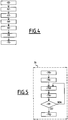
- the calculator 48 of the rear module 32A implements the algorithm for determining the composition of the train 1. This step is illustrated in detail on FIG. figure 5 .
- the computer 48 performs a comparison between the identifiers stored in the first storage means 38 and the couples of hitch identifiers stored in the first storage means 38. It then isolates the two identifiers contained in any pair of stored hitch IDs.
- the two identifiers that do not appear in any pair of stored hitch identifiers are the identifier Id 30A and the identifier Id 32C .
- the calculator 48 then arbitrarily isolates one of the two identifiers, for example the identifier Id 32C , and designates it as the identifier of a module of the presumed tail unit of the train 1.
- the calculator 48 designates also the identifier Id 32C as being the first current identifier and transmits it to the second storage means 46, which stores it in the table 49.
- the calculator 48 designates the identifier Id 30A as being the identifier of a module of the 1
- the calculator 48 designates the identifier Id 30A as being the identifier of a module of the suspected tail unit of the train 1, the identifier Id 32C being designated as being the identifier of a module of the presumed head unit of train 1.
- the computer 48 searches, in the second storage means 46, for the first current identifier among the pairs of stored unit identifiers.
- the computer 48 then isolates the pair of unit identifiers comprising the first current identifier and isolates the other identifier of this pair, the computer 48 then designating this identifier as the second current identifier.
- the calculator 48 transmits the second current identifier to the second storage means 46, which store it in the table 49.
- the computer 48 searches, in the first storage means 38, the second current identifier among the couples of hitch identifiers stored. The computer 48 then isolates the pair of hitch identifiers comprising the second current identifier and isolates the other identifier of this pair, the computer 48 then designating this identifier as the first current identifier. The computer 48 transmits the first current identifier to the second storage means 46, which stores it in the table 49.
- a subsequent step 70e is then implemented by the computer 48, the step 70e being identical to the step 70c.
- the calculator 48 compares the second current identifier with the identifier designated in step 70b as being the identifier of a module of the presumed head unit of the train 1, at the same time. instance Id 30A .
- step 70d is re-performed.
- a subsequent step 70g is implemented by the rear module 32A as described below.
- step 70g the message processing means 40 produce a message containing the content of the table 49.
- the message processing means 40 also elaborate, during this same step, a request for confirmation of presence of the message. one unit, to the electrical coupling coupler 21 of the unit 10A, and the electric coupling coupler 22 of the unit 10C.
- the message processing means 40 transmit, via the rear switch 36A, the message containing the content of the table 49, as well as the presence confirmation request to the electrical coupling coupler 22 of the unit 10C, on the general network 18.
- the request to confirm the presence of a unit, to the electric coupling coupler 21 of the unit 10A is directly transmitted by the message processing means 40 to the electric coupling coupler 21, via the rear switch 36A.
- the electric coupling coupler 21, respectively 22, of the unit 10A, respectively 10C indicates that no unit is connected to the unit 10A, respectively to the unit 10C. If, during step 70g, at least one of the two electrical couplers interrogated indicates that a unit is connected, the method for determining the composition of the train 1 is interrupted during a step 72, not shown. An operator can then intervene to perform, for example, a maintenance operation on the hitch communication links and / or the general network.
- the algorithm for determining the composition of the train 1 implemented by the computer 48 is interrupted in the case where a given security management module appears to be connected, via coupling communication links, to two different modules. .
- the method comprises an additional step 74, not shown, performed after step 70g.
- the message processing means 40 develop a test request for the hitch communication link 12 and a test request for the hitch communication link 14.
- the message processing means 40 transmit, via the rear switch 36A, the test request of the hitch communication link 12 to the module 30B, on the general network 18. They also issue the test request of the hitch communication link 14 to the 32B modules , 30C, on the general network 18. If, in step 74, at least one module indicates that the hitch communication link with which it is associated is defective, step 72 is performed.
- the steps 70b, 70c, 70d, 70e, 70f and 70g are implemented, in parallel, by the modules 30A, 30B, 30C, 32B, 32C.
- the method for determining the composition of the train 1 according to this embodiment of the invention thus makes it possible to dispense with the use of equipment on the ground.
- the method for determining the composition of the train 1 according to this embodiment of the invention does not impose particular constraints on the safety aspect or not of the hitch communication links 12, 14, unlike the second embodiment described later.
- This first embodiment constitutes the preferred embodiment of the invention.
- the security management modules belonging to the same device are connected by a wired link.
- each security management module has access to the identifier of the module belonging to the same device, and the second storage means 46 stores this identifier, before the implementation of the method according to the invention.
- the second storage means 46 are not parameterized by an operator.
- the identifiers Id 30A and Id 32A follow a rule indicating the membership of the front module 30A and the rear module 32A to the device 24A.
- the computer 48 is able to apply, for all the identifiers stored in the first storage means 38, a recognition rule of the identifier of the other security management module belonging to the device 24A, different from the rear module 32A.
- this other module is the front module 30A.
- the calculator 48 identifies the identifier Id 30A , by means of the recognition rule. The calculator 48 then transmits this identifier Id 30A to the second storage means 46, which store it.
- FIG 6 illustrates a second embodiment, for which elements similar to the first embodiment described above are identified by identical references.
- each security management device 24A, 24B, 24C respectively has only one module 76A, 76B, or 76C security management respectively.
- the data transmission means 26A, 26B, 26C respectively comprise a single switch 78A, 78B, 78C, respectively.
- each module 76A, 76B, 76C has a front portion having a first identifier, and a rear portion having a second identifier. Except for these features, the modules 76A, 76B, 76C are analogous to the modules 30A, 30B, 30C, 32A, 32B, 32C of the first embodiment.
- Each switch 78A, 78B, respectively 78C is connected on the one hand to a module 76A, 76B, respectively 76C and on the other hand to the general network 18.
- the switch 78A, respectively 78C is further connected via a communication link. hitch 80, respectively 81, to the switch 78B.
- each switch 78A, 78B, 78C is adapted to transmit a message to the or each switch to which it is connected via a hitch communication link 80, 81 as well as to receive a message from this or these switch (s), and address it to the module to which it is connected.
- the switches 78A, 78B, 78C are analogous to the switches 34A, 34B, 34C, 36A, 36B, 36C of the first embodiment.
- switches 78A, 78B, 78C are replaced by any means for transmitting data over a wired or non-wired network.
- each of the data transmission means 26A, 26B, respectively 26C comprises a front switch and a rear switch, the front and rear switches being connected to the module 76A, 76B, 76C respectively.
- each hitch communication link 80, 81 is a highly secure link, able to guarantee, in safety, the identity of the recipient and the integrity of the data it transmits.
- the train 1 is at a standstill and the first storage means 38 store the two identifiers of the module 76B.
- the message processing means 40 transmit on the general network 18, via the switch 78B, the unsecured broadcast message comprising the two identifiers of the module 76B.
- the first storage means 38 of the module 76B receive on the general network 18, via the switch 78B, the identifiers contained in the unsecured broadcast messages from the modules 76A, 76C. The first storage means 38 then store these identifiers.
- the message processing means 40 of the module 76B elaborate several secure messages, each secure message comprising the first identifier or the second identifier of the module 76B, and one of the identifiers of a module different from the module. 76B.
- the message processing means 40 thus elaborate a number of secure messages equal to twice the number of identifiers received during the previous step 62.
- the message processing means 40 transmit, via the switch 78B, on the hitch communication link 80, respectively 81, and on the general network 18, the secured messages comprising the first identifier, respectively the second identifier, according to a mode. conventional security transmission, point-to-point bidirectional link type.
- the front and rearward portions of the security management modules according to this second embodiment are similar to the front and rear modules respectively of the first embodiment. With this substitution, the following steps 64, 66, 68, 70b, 70c, 70d, 70e, 70f, 70g, 72 and 74 are identical to the corresponding steps of the method according to the first embodiment, and are therefore not described again. .
- steps 70b, 70c, 70d, 70e, 70f and 70g are also implemented, in parallel, by the modules 76A, 76C.
- the method for determining the composition of a train according to the invention thus makes it possible to dispense with the use of equipment on the ground.
- N being an integer greater than or equal to two, preferably greater than or equal to four.
Claims (5)
- Bestimmungsverfahren für die Zusammensetzung eines Zugs (1), der mehrere in aufeinanderfolgende Einheiten (10A, 10B, 10C) gruppierte, miteinander verbundene Fahrzeuge, darunter eine Kopfeinheit (10A) und eine Heckeinheit (10C) umfasst, wobei der Zug (1) umfasst:- eine Sicherheitsmanagement-Vorrichtung (24A, 24B, 24C) pro Einheit (10A, 10B, 10C), wobei jede Vorrichtung (24A, 24B, 24C) zwei ihr eigene Kennungen hat,- eine Kupplungskommunikationsverbindung (12, 14; 80, 81) für jedes Paar angrenzender Einheiten, wobei jede Kupplungskommunikationsverbindung (12, 14; 80, 81) nur zwei Vorrichtungen (24A, 24B, 24C) angrenzender Einheiten verbindet,- ein allgemeines Netz (18), das alle Vorrichtungen (24A, 24B, 24C) miteinander verbindet,wobei das Verfahren einen Anfangsschritt (60) zum Aussenden, durch jede Vorrichtung (24A, 24B, 24C) über das allgemeine Netz (18), einer ihre zwei Kennungen umfassenden, nicht gesicherten Verbreitungsnachricht, und einen Schritt (62) zum Empfangen, durch jede Vorrichtung (24A, 24B, 24C), von die Kennungen der anderen Vorrichtungen (24A, 24B, 24C) beinhaltenden Nachrichten umfasst, wobei das Verfahren dadurch gekennzeichnet ist, dass es die folgenden Schritte umfasst:- Aussenden (63), über das allgemeine Netz (18) und über jede Kupplungskommunikationsverbindung (12, 14; 80, 81), durch mindestens eine Vorrichtung (24A, 24B, 24C), einer gesicherten Nachricht an eine der an die besagte Vorrichtung (24A, 24B, 24C) angrenzenden Vorrichtungen (24A, 24B, 24C), wobei die Nachricht eine der Kennungen der besagten Vorrichtung (24A, 24B, 24C) beinhaltet,- Aussenden (66), über das allgemeine Netz (18), durch jede Vorrichtung (24A, 24B, 24C), die eine Kennung einer anderem Vorrichtung (24A, 24B, 24C) empfangen hat, die durch eine Kupplungskommunikationsverbindung (12, 14; 80, 81) verbunden ist, mindestens einer Wiederherstellungsnachricht, die die zwei Kennungen der besagten Vorrichtung (24A, 24B, 24C) sowie die empfangene Kennung beinhaltet,- Empfangen (68), durch jede Vorrichtung (24A, 24B, 24C), der ausgesendeten Wiederherstellungsnachrichten, und- Bestimmen (70), durch mindestens eine Vorrichtung (24A, 24B, 24C), der Zusammensetzung des Zugs (1), wobei der Bestimmungsschritt (70) aus der Umsetzung eines vorbestimmten Algorithmus in der besagten Vorrichtung (24A, 24B, 24C) besteht.
- Verfahren nach Anspruch 1, dadurch gekennzeichnet, dass jede Einheit (10A, 10B, 10C) darüber hinaus zwei Kupplungsstromkoppler (21, 22) umfasst, wobei jeder Kupplungsstromkoppler (21, 22) dazu geeignet ist, das Vorhandensein einer anderen mit der besagten Einheit verbundenen Einheit (10A, 10B, 10C) zu erfassen, und dass beim Bestimmungsschritt (70) für die Zusammensetzung des Zugs (1) der Bestimmungsalgorithmus die folgenden Schritte umfasst:- Suchen (70b) einer vermutlichen Heckvorrichtung des Zugs durch Identifikation der zwei Vorrichtungen (24A, 24B, 24C), die über eine Kupplungskommunikationsverbindung (12, 14; 80, 81) nur mit einer einzigen anderen Vorrichtung (24A, 24B, 24C) verbunden sind, und die Wahl einer der zwei Vorrichtungen,- Suchen (70c) einer zweiten Vorrichtung (24A, 24B, 24C), die über eine Kupplungskommunikationsverbindung (12, 14; 80, 81) mit der Heckvorrichtung verbunden ist,- schrittweises Iterieren (70f) des vorhergehenden Schritts bis zur anderen Vorrichtung (24A, 24B, 24C), die über eine Kupplungskommunikationsverbindung (12, 14; 80, 81) nur mit einer einzigen anderen Vorrichtung (24A, 24B, 24C) verbunden ist, wobei die besagte andere Vorrichtung (24A, 24B, 24C) die mutmaßliche Kopfvorrichtung darstellt, und- Validieren (70g) der Vollständigkeit des Zugs (1), wobei die mutmaßlichen Kopf- und Heckeinheiten (10A, 10B, 10C), die jeweils der mutmaßlichen Kopfeinheit und der mutmaßlichen Heckeinheit entsprechen, durch Auslesen der entsprechenden Kupplungsstromkoppler (21, 22) als Enden des Zugs (1) bestätigt werden müssen.
- Verfahren nach Anspruch 2, dadurch gekennzeichnet, dass jede Vorrichtung (24A, 24B, 24C) zwei Sicherheitsmanagement-Module (30A, 30B, 30C, 32A, 32B, 32C) umfasst, wobei jedes Modul (30A, 30B, 30C, 32A, 32B, 32C) eine ihm eigene Kennung hat, und dass beim Anfangsschritt (60) zum Aussenden, durch jede Vorrichtung (24A, 24B, 24C), über das allgemeine Netz (18), einer ihre zwei Kennungen umfassenden, nicht gesicherten Verbreitungsnachricht, und beim Aussendeschritt (66), durch jede Vorrichtung (24A, 24B, 24C), über das allgemeine Netz (18), mindestens einer Wiederherstellungsnachricht, die ihre zwei Kennungen sowie die empfangene Kennung beinhaltet, die besagten zwei Kennungen die Kennungen der zwei Sicherheitsmanagement-Module (30A, 30B, 30C, 32A, 32B, 32C) sind, die sie umfasst, wobei jedes Modul (30A, 30B, 30C, 32A, 32B, 32C) seine eigene Kennung über das allgemeine Netz (18) aussendet.
- Verfahren nach Anspruch 2, dadurch gekennzeichnet, dass jede Vorrichtung (24A, 24B, 24C) ein Sicherheitsmanagement-Modul (76A, 76B, 76C) umfasst, wobei jedes Modul (76A, 76B, 76C) zwei ihm eigene Kennungen hat, und dass beim Anfangsschritt (60) zum Aussenden, durch jede Vorrichtung (24A, 24B, 24C) über das allgemeine Netz (18), einer ihre zwei Kennungen umfassenden, nicht gesicherten Verbreitungsnachricht, und beim Aussendeschritt (66), durch jede Vorrichtung (24A, 24B, 24C) über das allgemeine Netz (18), mindestens einer Wiederherstellungsnachricht, die ihre zwei Kennungen sowie die empfangene Kennung beinhaltet, die besagten zwei Kennungen die Kennungen des Sicherheitsmanagement-Moduls (76A, 76B, 76C) sind, die sie beinhaltet.
- Verfahren nach einem der vorhergehenden Ansprüche, dadurch gekennzeichnet, dass beim Aussendeschritt (66), durch jede Vorrichtung (24A, 24B, 24C) über das allgemeine Netz (18), mindestens einer Wiederherstellungsnachricht, die ihre zwei Kennungen sowie die empfangene Kennung beinhaltet, zwei Vorrichtungen (24A, 24B, 24C) darüber hinaus über das allgemeine Netz (18) parallel eine Nachricht aussenden, die ihre zwei Kennungen sowie den Wert einer Variablen angibt, die das Vorhandensein oder nicht Vorhandensein einer angrenzenden Einheit angibt.
Applications Claiming Priority (1)
| Application Number | Priority Date | Filing Date | Title |
|---|---|---|---|
| FR1256126A FR2992620B1 (fr) | 2012-06-27 | 2012-06-27 | Train et procede de determination de la composition d'un tel train en securite |
Publications (3)
| Publication Number | Publication Date |
|---|---|
| EP2679466A1 EP2679466A1 (de) | 2014-01-01 |
| EP2679466B1 EP2679466B1 (de) | 2015-04-08 |
| EP2679466B2 true EP2679466B2 (de) | 2018-06-27 |
Family
ID=47049254
Family Applications (1)
| Application Number | Title | Priority Date | Filing Date |
|---|---|---|---|
| EP13173858.5A Active EP2679466B2 (de) | 2012-06-27 | 2013-06-26 | Sicheres Verfahren zu Bestimmung der Zusammenstellung eines Zugs |
Country Status (8)
| Country | Link |
|---|---|
| US (1) | US9221479B2 (de) |
| EP (1) | EP2679466B2 (de) |
| KR (1) | KR102131675B1 (de) |
| CN (1) | CN103507820B (de) |
| BR (1) | BR102013016687B1 (de) |
| CA (1) | CA2819848C (de) |
| ES (1) | ES2541903T5 (de) |
| FR (1) | FR2992620B1 (de) |
Families Citing this family (9)
| Publication number | Priority date | Publication date | Assignee | Title |
|---|---|---|---|---|
| CN104394240B (zh) * | 2014-11-13 | 2017-08-22 | 大连理工大学 | 一种列车乘客信息系统联挂解挂方法 |
| US10173698B2 (en) | 2015-02-09 | 2019-01-08 | General Electric Company | Communication system and method of a vehicle consist |
| US9862392B2 (en) * | 2015-02-09 | 2018-01-09 | General Electric Company | Communication system and method of a vehicle consist |
| DE102015204437A1 (de) * | 2015-03-12 | 2016-09-15 | Siemens Aktiengesellschaft | Verfahren und Vorrichtung zum Ermitteln eines Signalbegriffes für ein Schienenfahrzeug |
| US10112632B2 (en) | 2015-11-12 | 2018-10-30 | Trapeze Software Ulc | Method and system for rail vehicle coupling determination |
| US10029704B2 (en) * | 2016-08-04 | 2018-07-24 | Progress Rail Locomotive Inc. | Consist adhesion level control system for locomotives |
| DE102017113213A1 (de) * | 2017-06-15 | 2018-12-20 | Asto Telematics Gmbh | Anordnung zur Zusammenstellung und/oder Bestimmung der Wagenreihung und/oder Überprüfung der Vollständigkeit eines Schienenfahrzeugs, ein Verfahren und dessen Verwendung |
| EP3789263B1 (de) | 2019-09-04 | 2024-03-06 | Ovinto cvba | Verfahren und vorrichtung zur überwachung der konfiguration eines zuges |
| CN114802357B (zh) * | 2022-03-29 | 2023-08-25 | 卡斯柯信号有限公司 | 一种多列车连挂状态的安全识别方法、装置、设备及介质 |
Citations (4)
| Publication number | Priority date | Publication date | Assignee | Title |
|---|---|---|---|---|
| US20060180709A1 (en) † | 2005-02-11 | 2006-08-17 | Luc Breton | Method and system for IP train inauguration |
| DE102006018163A1 (de) † | 2006-04-19 | 2007-10-25 | Siemens Ag | Verfahren zur automatischen Adressvergabe |
| US20110224850A1 (en) † | 2007-12-21 | 2011-09-15 | Nomad Spectrum Limited | Component Vehicle |
| DE102010014333A1 (de) † | 2010-04-07 | 2011-10-13 | Siemens Aktiengesellschaft | Verfahren und Vorrichtung zur Bestimmung der Zuglänge mehrerer gekuppelter Triebfahrzeuge |
Family Cites Families (19)
| Publication number | Priority date | Publication date | Assignee | Title |
|---|---|---|---|---|
| JPS582864B2 (ja) * | 1978-04-07 | 1983-01-19 | 株式会社ナブコ | 列車の自動連結解放装置 |
| US5777547A (en) * | 1996-11-05 | 1998-07-07 | Zeftron, Inc. | Car identification and ordering system |
| DE19858922C1 (de) * | 1998-12-19 | 2000-07-06 | Deutsche Bahn Ag | Verfahren zum Bestimmen der physischen Reihenfolge von Fahrzeugen eines zusammengestellten Zuges und Anordnung zur Durchführung des Verfahrens |
| US6449536B1 (en) * | 2000-07-14 | 2002-09-10 | Canac, Inc. | Remote control system for locomotives |
| AU2001280020B2 (en) * | 2000-07-20 | 2005-09-22 | 2283188 Ontario Limited | System and method for transportation vehicle monitoring, feedback and control |
| US7131614B2 (en) * | 2003-05-22 | 2006-11-07 | General Electric Company | Locomotive control system and method |
| DE10152965B4 (de) * | 2001-10-26 | 2006-02-09 | Db Regio Ag | Verfahren zum Betreiben eines Kommunikationssystems für Züge |
| DE10245973B4 (de) * | 2002-09-30 | 2007-11-15 | Deutsche Bahn Regio Ag | Buskopplung |
| FR2857644B1 (fr) * | 2003-07-16 | 2006-03-10 | Inrets | Dispositif et procede de positionnement et de controle de vehicules ferroviaires a bandes de frequence ultra larges. |
| EP1677184A1 (de) * | 2003-07-22 | 2006-07-05 | Softbank Corp. | Inhaltspräsentationseinrichtung, verwaltungs-server, inhaltspräsentationssystem und inhaltspräsentationsverfahren |
| US8073582B2 (en) * | 2006-06-06 | 2011-12-06 | General Electric Company | System and method for establishing a wireless-based communication link between a pair of locomotives |
| WO2010007217A1 (fr) * | 2008-07-16 | 2010-01-21 | Siemens Transportation Systems Sas | Système de détermination de propriétés du mouvement d'un véhicule guidé |
| JP5358503B2 (ja) * | 2010-03-26 | 2013-12-04 | 株式会社日立国際電気 | ネットワーク管理システム、ネットワーク管理方法およびネットワーク管理装置 |
| US8473128B2 (en) * | 2010-05-19 | 2013-06-25 | L.B. Foster Rail Technologies Canada, Ltd. | Optimizing rail track performance |
| CA2818605A1 (en) * | 2010-11-23 | 2012-05-31 | Siemens Sas | Method for securing a control system of a reconfigurable multi-unit vehicle, and secured control system |
| FR2988064B1 (fr) * | 2012-03-15 | 2014-04-18 | Alstom Transport Sa | Systeme embarque de generation d'un signal de localisation d'un vehicule ferroviaire |
| US8630758B2 (en) * | 2012-05-08 | 2014-01-14 | Eric Ehrler | Method and apparatus for safety protocol verification, control and management |
| US9436830B2 (en) * | 2012-10-17 | 2016-09-06 | Sandisk Technologies Llc | Securing access of removable media devices |
| US9961384B2 (en) * | 2012-12-20 | 2018-05-01 | Nagravision S.A. | Method and a security module configured to enforce processing of management messages |
-
2012
- 2012-06-27 FR FR1256126A patent/FR2992620B1/fr active Active
-
2013
- 2013-06-25 CA CA2819848A patent/CA2819848C/fr active Active
- 2013-06-26 EP EP13173858.5A patent/EP2679466B2/de active Active
- 2013-06-26 ES ES13173858.5T patent/ES2541903T5/es active Active
- 2013-06-26 US US13/928,183 patent/US9221479B2/en active Active
- 2013-06-27 BR BR102013016687-1A patent/BR102013016687B1/pt active IP Right Grant
- 2013-06-27 KR KR1020130074685A patent/KR102131675B1/ko active IP Right Grant
- 2013-06-27 CN CN201310263568.8A patent/CN103507820B/zh active Active
Patent Citations (4)
| Publication number | Priority date | Publication date | Assignee | Title |
|---|---|---|---|---|
| US20060180709A1 (en) † | 2005-02-11 | 2006-08-17 | Luc Breton | Method and system for IP train inauguration |
| DE102006018163A1 (de) † | 2006-04-19 | 2007-10-25 | Siemens Ag | Verfahren zur automatischen Adressvergabe |
| US20110224850A1 (en) † | 2007-12-21 | 2011-09-15 | Nomad Spectrum Limited | Component Vehicle |
| DE102010014333A1 (de) † | 2010-04-07 | 2011-10-13 | Siemens Aktiengesellschaft | Verfahren und Vorrichtung zur Bestimmung der Zuglänge mehrerer gekuppelter Triebfahrzeuge |
Non-Patent Citations (1)
| Title |
|---|
| Normentwurf zu IEC 61375-2-5 "Electronic Railway Equipment- Train Backbone- Part 2.5: Ethernet Train Backbone" † |
Also Published As
| Publication number | Publication date |
|---|---|
| CA2819848C (fr) | 2020-10-13 |
| CA2819848A1 (fr) | 2013-12-27 |
| ES2541903T5 (es) | 2018-10-16 |
| KR20140001170A (ko) | 2014-01-06 |
| KR102131675B1 (ko) | 2020-07-08 |
| US9221479B2 (en) | 2015-12-29 |
| BR102013016687A2 (pt) | 2015-08-25 |
| EP2679466A1 (de) | 2014-01-01 |
| US20140005863A1 (en) | 2014-01-02 |
| FR2992620A1 (fr) | 2014-01-03 |
| BR102013016687B1 (pt) | 2021-07-13 |
| ES2541903T3 (es) | 2015-07-28 |
| CN103507820B (zh) | 2017-07-28 |
| BR102013016687A8 (pt) | 2016-05-31 |
| FR2992620B1 (fr) | 2014-08-15 |
| EP2679466B1 (de) | 2015-04-08 |
| CN103507820A (zh) | 2014-01-15 |
Similar Documents
| Publication | Publication Date | Title |
|---|---|---|
| EP2679466B2 (de) | Sicheres Verfahren zu Bestimmung der Zusammenstellung eines Zugs | |
| EP2832069B1 (de) | System zur überwachung der sicherheit einer architektur | |
| EP1992109B1 (de) | Verfahren zur einteilung von knoten eines netzwerkes in knotengruppen, computerprogramm zur umsetzung eines derartigen verfahrens und knoten eines knotennetzwerkes bildende kommunikationsvorrichtung | |
| EP2954648B1 (de) | Datenroutingverfahren, computerprogramm, netzwerksteuerung und dazugehörige netzwerke | |
| EP0959602A1 (de) | Anordnung für Nachrichtübertragung mit verbesserten Stationen und entsprechendes Verfahren | |
| FR2952257A1 (fr) | Procede et dispositif de configuration d'un systeme d'information de maintenance embarque dans un aeronef | |
| EP1787475A1 (de) | Schutz und überwachung von inhaltsverbreitung in einem telekommunikationsnetzwerk | |
| CA2819517C (fr) | Procede de fiabilisation de donnees, calculateur, ensembles de communication et systeme de gestion ferroviaire associe | |
| EP2643198B1 (de) | Verfahren zur sicherung eines steuersystems eines neukonfigurierbaren fahrzeugs aus mehreren einheiten sowie gesichertes steuersystem | |
| EP2599683A1 (de) | Vorrichtung und Verfahren zur Signalisierung für einen Zug | |
| EP2751959B1 (de) | Verfahren zum austausch von daten zwischen knoten in einem server-cluster und servercluster zur durchführung des verfahrens | |
| EP0634069B1 (de) | Anlage und verfahren zur uebertragung von daten in einem funknetz | |
| EP3251399B1 (de) | Verfahren zum testen einer funkkommunikationsvorrichtung eines gateways in einem gateway-pool | |
| FR2947127A1 (fr) | Systeme de simulation ou de test, et procede associe. | |
| FR2836611A1 (fr) | Procede de communication reseau avec une carte a puce par messages asynchrones | |
| WO2015177452A1 (fr) | Commutateur de trames numeriques | |
| EP0637417B1 (de) | Datenübertragungseinrichtung und verfahren für funknetz | |
| FR2665967A1 (fr) | Reseau informatique a anneau d'ecriture et anneau de lecture, station inserable dans un tel reseau, procede de connexion, de reconfiguration et protocole d'acces a un tel reseau. | |
| FR2794918A1 (fr) | Procede et dispositif d'emission, de traitement et de reception d'un paquet de donnees dans un reseau de communication | |
| FR2899986A1 (fr) | Procede de configuration de calculateurs et procede de communication, calculateur pour ces procedes | |
| EP2746977A1 (de) | Verfahren zur Erzeugung einer Überwachungsmodellversion eines Informationssystems | |
| FR3095914A1 (fr) | Procédé de routage dynamique dans un réseau d’objets connectés | |
| FR2736230A1 (fr) | Installation du type reseau radio de transmission de donnees avec rouage | |
| FR2791502A1 (fr) | Procede et dispositif de determination d'un chemin d'un paquet de donnees dans un reseau de communication | |
| EP3046368A1 (de) | Verfahren zur erfassung von leitwegdaten in einem ad-hoc-netz, und auswahlverfahren des leitwegs auf der basis der erfassten informationen |
Legal Events
| Date | Code | Title | Description |
|---|---|---|---|
| PUAI | Public reference made under article 153(3) epc to a published international application that has entered the european phase |
Free format text: ORIGINAL CODE: 0009012 |
|
| AK | Designated contracting states |
Kind code of ref document: A1 Designated state(s): AL AT BE BG CH CY CZ DE DK EE ES FI FR GB GR HR HU IE IS IT LI LT LU LV MC MK MT NL NO PL PT RO RS SE SI SK SM TR |
|
| AX | Request for extension of the european patent |
Extension state: BA ME |
|
| 17P | Request for examination filed |
Effective date: 20140701 |
|
| RBV | Designated contracting states (corrected) |
Designated state(s): AL AT BE BG CH CY CZ DE DK EE ES FI FR GB GR HR HU IE IS IT LI LT LU LV MC MK MT NL NO PL PT RO RS SE SI SK SM TR |
|
| GRAP | Despatch of communication of intention to grant a patent |
Free format text: ORIGINAL CODE: EPIDOSNIGR1 |
|
| RIC1 | Information provided on ipc code assigned before grant |
Ipc: B61L 25/02 20060101ALN20140929BHEP Ipc: B61L 15/00 20060101AFI20140929BHEP |
|
| INTG | Intention to grant announced |
Effective date: 20141023 |
|
| RAP1 | Party data changed (applicant data changed or rights of an application transferred) |
Owner name: ALSTOM TRANSPORT TECHNOLOGIES |
|
| GRAS | Grant fee paid |
Free format text: ORIGINAL CODE: EPIDOSNIGR3 |
|
| GRAA | (expected) grant |
Free format text: ORIGINAL CODE: 0009210 |
|
| AK | Designated contracting states |
Kind code of ref document: B1 Designated state(s): AL AT BE BG CH CY CZ DE DK EE ES FI FR GB GR HR HU IE IS IT LI LT LU LV MC MK MT NL NO PL PT RO RS SE SI SK SM TR |
|
| REG | Reference to a national code |
Ref country code: GB Ref legal event code: FG4D Free format text: NOT ENGLISH |
|
| REG | Reference to a national code |
Ref country code: CH Ref legal event code: EP |
|
| REG | Reference to a national code |
Ref country code: IE Ref legal event code: FG4D Free format text: LANGUAGE OF EP DOCUMENT: FRENCH |
|
| REG | Reference to a national code |
Ref country code: DE Ref legal event code: R096 Ref document number: 602013001446 Country of ref document: DE Effective date: 20150513 |
|
| REG | Reference to a national code |
Ref country code: AT Ref legal event code: REF Ref document number: 720319 Country of ref document: AT Kind code of ref document: T Effective date: 20150515 |
|
| REG | Reference to a national code |
Ref country code: FR Ref legal event code: PLFP Year of fee payment: 3 |
|
| REG | Reference to a national code |
Ref country code: NL Ref legal event code: T3 |
|
| REG | Reference to a national code |
Ref country code: SE Ref legal event code: TRGR Ref country code: ES Ref legal event code: FG2A Ref document number: 2541903 Country of ref document: ES Kind code of ref document: T3 Effective date: 20150728 |
|
| REG | Reference to a national code |
Ref country code: NL Ref legal event code: T3 |
|
| REG | Reference to a national code |
Ref country code: AT Ref legal event code: MK05 Ref document number: 720319 Country of ref document: AT Kind code of ref document: T Effective date: 20150408 |
|
| REG | Reference to a national code |
Ref country code: LT Ref legal event code: MG4D |
|
| PG25 | Lapsed in a contracting state [announced via postgrant information from national office to epo] |
Ref country code: PT Free format text: LAPSE BECAUSE OF FAILURE TO SUBMIT A TRANSLATION OF THE DESCRIPTION OR TO PAY THE FEE WITHIN THE PRESCRIBED TIME-LIMIT Effective date: 20150810 Ref country code: NO Free format text: LAPSE BECAUSE OF FAILURE TO SUBMIT A TRANSLATION OF THE DESCRIPTION OR TO PAY THE FEE WITHIN THE PRESCRIBED TIME-LIMIT Effective date: 20150708 Ref country code: LT Free format text: LAPSE BECAUSE OF FAILURE TO SUBMIT A TRANSLATION OF THE DESCRIPTION OR TO PAY THE FEE WITHIN THE PRESCRIBED TIME-LIMIT Effective date: 20150408 Ref country code: HR Free format text: LAPSE BECAUSE OF FAILURE TO SUBMIT A TRANSLATION OF THE DESCRIPTION OR TO PAY THE FEE WITHIN THE PRESCRIBED TIME-LIMIT Effective date: 20150408 Ref country code: FI Free format text: LAPSE BECAUSE OF FAILURE TO SUBMIT A TRANSLATION OF THE DESCRIPTION OR TO PAY THE FEE WITHIN THE PRESCRIBED TIME-LIMIT Effective date: 20150408 |
|
| PG25 | Lapsed in a contracting state [announced via postgrant information from national office to epo] |
Ref country code: RS Free format text: LAPSE BECAUSE OF FAILURE TO SUBMIT A TRANSLATION OF THE DESCRIPTION OR TO PAY THE FEE WITHIN THE PRESCRIBED TIME-LIMIT Effective date: 20150408 Ref country code: IS Free format text: LAPSE BECAUSE OF FAILURE TO SUBMIT A TRANSLATION OF THE DESCRIPTION OR TO PAY THE FEE WITHIN THE PRESCRIBED TIME-LIMIT Effective date: 20150808 Ref country code: GR Free format text: LAPSE BECAUSE OF FAILURE TO SUBMIT A TRANSLATION OF THE DESCRIPTION OR TO PAY THE FEE WITHIN THE PRESCRIBED TIME-LIMIT Effective date: 20150709 Ref country code: LV Free format text: LAPSE BECAUSE OF FAILURE TO SUBMIT A TRANSLATION OF THE DESCRIPTION OR TO PAY THE FEE WITHIN THE PRESCRIBED TIME-LIMIT Effective date: 20150408 Ref country code: AT Free format text: LAPSE BECAUSE OF FAILURE TO SUBMIT A TRANSLATION OF THE DESCRIPTION OR TO PAY THE FEE WITHIN THE PRESCRIBED TIME-LIMIT Effective date: 20150408 |
|
| REG | Reference to a national code |
Ref country code: DE Ref legal event code: R026 Ref document number: 602013001446 Country of ref document: DE |
|
| PLBI | Opposition filed |
Free format text: ORIGINAL CODE: 0009260 |
|
| PG25 | Lapsed in a contracting state [announced via postgrant information from national office to epo] |
Ref country code: DK Free format text: LAPSE BECAUSE OF FAILURE TO SUBMIT A TRANSLATION OF THE DESCRIPTION OR TO PAY THE FEE WITHIN THE PRESCRIBED TIME-LIMIT Effective date: 20150408 Ref country code: MC Free format text: LAPSE BECAUSE OF FAILURE TO SUBMIT A TRANSLATION OF THE DESCRIPTION OR TO PAY THE FEE WITHIN THE PRESCRIBED TIME-LIMIT Effective date: 20150408 Ref country code: EE Free format text: LAPSE BECAUSE OF FAILURE TO SUBMIT A TRANSLATION OF THE DESCRIPTION OR TO PAY THE FEE WITHIN THE PRESCRIBED TIME-LIMIT Effective date: 20150408 |
|
| PLAX | Notice of opposition and request to file observation + time limit sent |
Free format text: ORIGINAL CODE: EPIDOSNOBS2 |
|
| 26 | Opposition filed |
Opponent name: SIEMENS AKTIENGESELLSCHAFT Effective date: 20160108 |
|
| PG25 | Lapsed in a contracting state [announced via postgrant information from national office to epo] |
Ref country code: LU Free format text: LAPSE BECAUSE OF FAILURE TO SUBMIT A TRANSLATION OF THE DESCRIPTION OR TO PAY THE FEE WITHIN THE PRESCRIBED TIME-LIMIT Effective date: 20150626 Ref country code: SK Free format text: LAPSE BECAUSE OF FAILURE TO SUBMIT A TRANSLATION OF THE DESCRIPTION OR TO PAY THE FEE WITHIN THE PRESCRIBED TIME-LIMIT Effective date: 20150408 Ref country code: PL Free format text: LAPSE BECAUSE OF FAILURE TO SUBMIT A TRANSLATION OF THE DESCRIPTION OR TO PAY THE FEE WITHIN THE PRESCRIBED TIME-LIMIT Effective date: 20150408 Ref country code: RO Free format text: LAPSE BECAUSE OF NON-PAYMENT OF DUE FEES Effective date: 20150408 Ref country code: CZ Free format text: LAPSE BECAUSE OF FAILURE TO SUBMIT A TRANSLATION OF THE DESCRIPTION OR TO PAY THE FEE WITHIN THE PRESCRIBED TIME-LIMIT Effective date: 20150408 |
|
| REG | Reference to a national code |
Ref country code: IE Ref legal event code: MM4A |
|
| PG25 | Lapsed in a contracting state [announced via postgrant information from national office to epo] |
Ref country code: IE Free format text: LAPSE BECAUSE OF NON-PAYMENT OF DUE FEES Effective date: 20150626 |
|
| PG25 | Lapsed in a contracting state [announced via postgrant information from national office to epo] |
Ref country code: SI Free format text: LAPSE BECAUSE OF FAILURE TO SUBMIT A TRANSLATION OF THE DESCRIPTION OR TO PAY THE FEE WITHIN THE PRESCRIBED TIME-LIMIT Effective date: 20150408 |
|
| PLAF | Information modified related to communication of a notice of opposition and request to file observations + time limit |
Free format text: ORIGINAL CODE: EPIDOSCOBS2 |
|
| REG | Reference to a national code |
Ref country code: FR Ref legal event code: PLFP Year of fee payment: 4 |
|
| PLBB | Reply of patent proprietor to notice(s) of opposition received |
Free format text: ORIGINAL CODE: EPIDOSNOBS3 |
|
| RAP2 | Party data changed (patent owner data changed or rights of a patent transferred) |
Owner name: ALSTOM TRANSPORT TECHNOLOGIES |
|
| PG25 | Lapsed in a contracting state [announced via postgrant information from national office to epo] |
Ref country code: MT Free format text: LAPSE BECAUSE OF FAILURE TO SUBMIT A TRANSLATION OF THE DESCRIPTION OR TO PAY THE FEE WITHIN THE PRESCRIBED TIME-LIMIT Effective date: 20150408 |
|
| REG | Reference to a national code |
Ref country code: CH Ref legal event code: PL |
|
| PG25 | Lapsed in a contracting state [announced via postgrant information from national office to epo] |
Ref country code: LI Free format text: LAPSE BECAUSE OF NON-PAYMENT OF DUE FEES Effective date: 20160630 Ref country code: CH Free format text: LAPSE BECAUSE OF NON-PAYMENT OF DUE FEES Effective date: 20160630 |
|
| PG25 | Lapsed in a contracting state [announced via postgrant information from national office to epo] |
Ref country code: HU Free format text: LAPSE BECAUSE OF FAILURE TO SUBMIT A TRANSLATION OF THE DESCRIPTION OR TO PAY THE FEE WITHIN THE PRESCRIBED TIME-LIMIT; INVALID AB INITIO Effective date: 20130626 Ref country code: BG Free format text: LAPSE BECAUSE OF FAILURE TO SUBMIT A TRANSLATION OF THE DESCRIPTION OR TO PAY THE FEE WITHIN THE PRESCRIBED TIME-LIMIT Effective date: 20150408 |
|
| REG | Reference to a national code |
Ref country code: FR Ref legal event code: PLFP Year of fee payment: 5 |
|
| PG25 | Lapsed in a contracting state [announced via postgrant information from national office to epo] |
Ref country code: CY Free format text: LAPSE BECAUSE OF FAILURE TO SUBMIT A TRANSLATION OF THE DESCRIPTION OR TO PAY THE FEE WITHIN THE PRESCRIBED TIME-LIMIT Effective date: 20150408 |
|
| PG25 | Lapsed in a contracting state [announced via postgrant information from national office to epo] |
Ref country code: BE Free format text: LAPSE BECAUSE OF NON-PAYMENT OF DUE FEES Effective date: 20150630 |
|
| REG | Reference to a national code |
Ref country code: DE Ref legal event code: R082 Ref document number: 602013001446 Country of ref document: DE Representative=s name: LAVOIX MUNICH, DE Ref country code: DE Ref legal event code: R081 Ref document number: 602013001446 Country of ref document: DE Owner name: ALSTOM TRANSPORT TECHNOLOGIES, FR Free format text: FORMER OWNER: ALSTOM TRANSPORT TECHNOLOGIES, LEVALLOIS-PERRET, FR |
|
| RIC2 | Information provided on ipc code assigned after grant |
Ipc: B61L 15/00 20060101AFI20170926BHEP Ipc: B61L 25/02 20060101ALN20170926BHEP |
|
| PLAB | Opposition data, opponent's data or that of the opponent's representative modified |
Free format text: ORIGINAL CODE: 0009299OPPO |
|
| RIC2 | Information provided on ipc code assigned after grant |
Ipc: B61L 25/02 20060101ALN20171009BHEP Ipc: B61L 15/00 20060101AFI20171009BHEP |
|
| R26 | Opposition filed (corrected) |
Opponent name: SIEMENS AKTIENGESELLSCHAFT Effective date: 20160108 |
|
| REG | Reference to a national code |
Ref country code: FR Ref legal event code: CA Effective date: 20180103 |
|
| PUAH | Patent maintained in amended form |
Free format text: ORIGINAL CODE: 0009272 |
|
| STAA | Information on the status of an ep patent application or granted ep patent |
Free format text: STATUS: PATENT MAINTAINED AS AMENDED |
|
| PG25 | Lapsed in a contracting state [announced via postgrant information from national office to epo] |
Ref country code: SM Free format text: LAPSE BECAUSE OF FAILURE TO SUBMIT A TRANSLATION OF THE DESCRIPTION OR TO PAY THE FEE WITHIN THE PRESCRIBED TIME-LIMIT Effective date: 20150408 |
|
| REG | Reference to a national code |
Ref country code: FR Ref legal event code: PLFP Year of fee payment: 6 |
|
| 27A | Patent maintained in amended form |
Effective date: 20180627 |
|
| AK | Designated contracting states |
Kind code of ref document: B2 Designated state(s): AL AT BE BG CH CY CZ DE DK EE ES FI FR GB GR HR HU IE IS IT LI LT LU LV MC MK MT NL NO PL PT RO RS SE SI SK SM TR |
|
| REG | Reference to a national code |
Ref country code: DE Ref legal event code: R102 Ref document number: 602013001446 Country of ref document: DE |
|
| PG25 | Lapsed in a contracting state [announced via postgrant information from national office to epo] |
Ref country code: MK Free format text: LAPSE BECAUSE OF FAILURE TO SUBMIT A TRANSLATION OF THE DESCRIPTION OR TO PAY THE FEE WITHIN THE PRESCRIBED TIME-LIMIT Effective date: 20150408 |
|
| REG | Reference to a national code |
Ref country code: NL Ref legal event code: FP |
|
| REG | Reference to a national code |
Ref country code: SE Ref legal event code: RPEO |
|
| REG | Reference to a national code |
Ref country code: ES Ref legal event code: DC2A Ref document number: 2541903 Country of ref document: ES Kind code of ref document: T5 Effective date: 20181016 |
|
| PG25 | Lapsed in a contracting state [announced via postgrant information from national office to epo] |
Ref country code: AL Free format text: LAPSE BECAUSE OF FAILURE TO SUBMIT A TRANSLATION OF THE DESCRIPTION OR TO PAY THE FEE WITHIN THE PRESCRIBED TIME-LIMIT Effective date: 20150408 |
|
| PGFP | Annual fee paid to national office [announced via postgrant information from national office to epo] |
Ref country code: NL Payment date: 20230620 Year of fee payment: 11 Ref country code: FR Payment date: 20230627 Year of fee payment: 11 Ref country code: DE Payment date: 20230620 Year of fee payment: 11 |
|
| PGFP | Annual fee paid to national office [announced via postgrant information from national office to epo] |
Ref country code: TR Payment date: 20230620 Year of fee payment: 11 Ref country code: SE Payment date: 20230620 Year of fee payment: 11 |
|
| P01 | Opt-out of the competence of the unified patent court (upc) registered |
Effective date: 20230823 |
|
| PGFP | Annual fee paid to national office [announced via postgrant information from national office to epo] |
Ref country code: IT Payment date: 20230623 Year of fee payment: 11 Ref country code: GB Payment date: 20230622 Year of fee payment: 11 Ref country code: ES Payment date: 20230829 Year of fee payment: 11 |