EP2678259B1 - Seillastmesselement mit funkübertragung der messwerte - Google Patents
Seillastmesselement mit funkübertragung der messwerte Download PDFInfo
- Publication number
- EP2678259B1 EP2678259B1 EP12710166.5A EP12710166A EP2678259B1 EP 2678259 B1 EP2678259 B1 EP 2678259B1 EP 12710166 A EP12710166 A EP 12710166A EP 2678259 B1 EP2678259 B1 EP 2678259B1
- Authority
- EP
- European Patent Office
- Prior art keywords
- cable load
- cable
- receiver
- transmitter
- load measuring
- Prior art date
- Legal status (The legal status is an assumption and is not a legal conclusion. Google has not performed a legal analysis and makes no representation as to the accuracy of the status listed.)
- Active
Links
Images
Classifications
-
- B—PERFORMING OPERATIONS; TRANSPORTING
- B66—HOISTING; LIFTING; HAULING
- B66B—ELEVATORS; ESCALATORS OR MOVING WALKWAYS
- B66B19/00—Mining-hoist operation
- B66B19/06—Applications of signalling devices
-
- B—PERFORMING OPERATIONS; TRANSPORTING
- B66—HOISTING; LIFTING; HAULING
- B66B—ELEVATORS; ESCALATORS OR MOVING WALKWAYS
- B66B7/00—Other common features of elevators
- B66B7/06—Arrangements of ropes or cables
- B66B7/10—Arrangements of ropes or cables for equalising rope or cable tension
-
- B—PERFORMING OPERATIONS; TRANSPORTING
- B66—HOISTING; LIFTING; HAULING
- B66B—ELEVATORS; ESCALATORS OR MOVING WALKWAYS
- B66B7/00—Other common features of elevators
- B66B7/12—Checking, lubricating, or cleaning means for ropes, cables or guides
-
- B—PERFORMING OPERATIONS; TRANSPORTING
- B66—HOISTING; LIFTING; HAULING
- B66B—ELEVATORS; ESCALATORS OR MOVING WALKWAYS
- B66B7/00—Other common features of elevators
- B66B7/12—Checking, lubricating, or cleaning means for ropes, cables or guides
- B66B7/1207—Checking means
- B66B7/1215—Checking means specially adapted for ropes or cables
-
- G—PHYSICS
- G08—SIGNALLING
- G08C—TRANSMISSION SYSTEMS FOR MEASURED VALUES, CONTROL OR SIMILAR SIGNALS
- G08C17/00—Arrangements for transmitting signals characterised by the use of a wireless electrical link
- G08C17/02—Arrangements for transmitting signals characterised by the use of a wireless electrical link using a radio link
Definitions
- the present invention relates to a method and a device for determining the rope forces of a multi-cable conveyor system and evaluating the rope loads with correction specifications.
- Conveyors are essential systems for each mine in the world, with the help of which these conveyors can transport persons and material to the respective destinations in the mine, which can easily be several thousand meters deep, e.g. the case in the South African gold mines.
- the conventional construction of a conveyor system is such that a conveyor (e.g., bucket, skip or counterweight) is attached to the ends of the upper ropes. With the movement of the upper rope through the traction sheave, the conveyor is moved through the shaft. Depending on the particular depth of the conveying means, ie the length of the upper ropes in the shaft, different rope forces of the upper ropes can occur with each other. These differences must be compensated to ensure a uniform load capacity and thus a uniform load of the upper ropes.
- a conveyor e.g., bucket, skip or counterweight
- rope loads can be measured by conventional rope load gauges at the attachment points of the top rope to the conveyor and / or the load carrier, such as resistance gauges or other suitable means which provide an electrical signal corresponding to the respective rope load.
- the measured values of the rope load measuring elements are usually recorded manually, carried by hand to the surface of the mine and entered there in a data processing system, which is connected in doubt with an evaluation system.
- document DE 3307020 A1 discloses an arrangement for measuring rope forces, in which force gauges are arranged between a conveyor and ropes and the condition of friction grooves are monitored.
- a method of measuring rope loads in conveyors comprising the steps of providing rope load sensing elements in interconnections above the conveyor associated with at least one wireless transmitter, providing at least one wireless load level sensor at the mine surface level provided with an output interface, measuring the rope loads on the conveyor by means of the rope load measuring elements to determine rope loads, and wireless transmission of the rope load values from the transmitter to the receiver for rope load measurements.
- a method as described here provides the necessary security in the transmission of rope load readings from the conveyor to the surface of the well, with both human errors and mechanical errors of transmission substantially eliminated.
- the rope load readings are transmitted from the wireless receiver for rope load readings via the output interface directly to an evaluation system to ensure that the rope load readings are fed into the system without avoidable delay.
- a plurality of independent rope load sensing elements are provided to measure and transmit between the wireless transmitter and rope load readings receiver a corresponding plurality of independent rope load values.
- a rope load measuring element per upper cable is provided.
- radio transmission which may be radio relaying or WLAN.
- relay stations for the data to be transmitted which record the transmitted signal on the one hand, possibly amplify it and, on the other hand, deliver it again.
- a transmission module can be provided on the conveyor, which comprises at least one transmission antenna for the wireless transmissions of the rope load measurements to the surface, and to which the one or more independent load measuring elements are connected.
- the transmitter module may also include an interface, possibly in the form of an additional near-field antenna, a USB interface, a Bluetooth interface or an infrared interface, to be able to provide the measured cable loads to a receiver located within the conveyor is, as in the case of a laptop computer, a handheld or the like.
- a device for measuring cable loads of conveyor systems comprising at least one cable load measuring element for installation on a conveyor, at least one wireless transmitter for elevator rope load readings for installation on the conveyor, for connection to the rope load measuring elements or the; and at least one wireless load reading sensor for installation at the surface of the mine shaft, provided with an output interface for connection to an evaluation system, which device may have all those characteristics as already described in connection with the method.
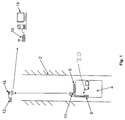
- FIG. 1 is a conveyor shaft 2 of a mine to recognize, in which a conveyor 4 can move up and down.
- the conveyor 4 is attached to a plurality of upper ropes (not shown) that the conveyor can lower into the shaft, or can pull to the surface or the upper end of the shaft.
- a rope load measuring element 6 is provided per upper cable (not shown) with which the respective cable load can be measured as a single, independent value for each measuring element. The determination of the rope loads via an intermediate harness in which the rope load measuring element is housed.
- the rope load measuring elements 6 are connected to a transmission module 8, wherein each rope load measuring element 6 has a separate and dedicated connection with the transmission module 8.
- the transmission module 8 is connected to an antenna 10 on the conveying means, which can transmit the read-out values of the rope load measuring elements 6 by radio to a corresponding antenna 14 to a receiver 12 which is located at the upper end of the shaft.
- the transmission module has six channels, so that with a number of more than six upper ropes and therefore correspondingly many rope load measuring elements, a correspondingly larger number of transmission modules 8 must be provided.
- the rope load measurements are again transmitted by radio to an additional receiver 16 connected to an evaluation system 18 for calculating the differences in rope loads and displaying the rope length correction values and / or the rope grooves of a cable carrier.
- the receiver 16 can also receive the measured values from more than one transmission module 8. So that the receiver 16 more than the six
- Each transmission module 6 sends an identifier before transmitting the six measured values, so that the receiver can assign the transmitted measured values to the respective transmitter module 6.
- the transmission of the respectively six measured values then takes place sequentially, ie one transmission module after the other.
- FIG. 1 it can be seen that another receiver 20 can be arranged within the conveying means 4 for receiving the rope load measured values which are supplied to the transmission module 8 by the rope load measuring elements 6.
Landscapes
- Engineering & Computer Science (AREA)
- Computer Networks & Wireless Communication (AREA)
- Physics & Mathematics (AREA)
- General Physics & Mathematics (AREA)
- Arrangements For Transmission Of Measured Signals (AREA)
- Control Of Conveyors (AREA)
- Force Measurement Appropriate To Specific Purposes (AREA)
Description
- Die vorliegende Erfindung bezieht sich auf ein Verfahren und eine Vorrichtung zur Bestimmung der Seilkräfte einer Mehrseilförderanlage und dem Auswerten der Seillasten mit Korrekturvorgaben.
- Förderanlagen sind wesentliche Systeme für jedes Bergwerk dieser Welt, mit deren Hilfe dieser Förderanlagen Personen und Material zu den jeweiligen Bestimmungsorten im Bergwerk transportiert werden können, die ohne Weiteres mehrere tausend Meter tief sein können, wie z.B. der Fall in den südafrikanischen Goldminen.
- Der herkömmliche Aufbau einer Förderanlage ist derart, dass an den Enden der Oberseile ein Fördermittel (z.B. Förderkorb, Skip oder Gegengewicht) befestigt ist. Mit der Bewegung des Oberseils durch die Treibscheibe, wird das Fördermittel durch den Schacht bewegt. Abhängig von der jeweiligen Teufe des Fördermittels, also Länge der Oberseile im Schacht, kann es zu unterschiedlichen Seilkräften der Oberseile untereinander kommen. Diese Unterschiede müssen ausgeglichen werden, um eine gleichmäßige Tragkraft und damit eine gleichmäßige Beanspruchung der Oberseile zu gewährleisten.
- Seillasten als solche können durch herkömmliche Seillastmesselemente an den Befestigungspunkten des Oberseils am Fördermittel und/oder dem Lastträger gemessen werden, wie zum Beispiel Widerstandsmessstreifen oder andere geeignete Mittel, die ein elektrisches Signal abgeben, das der jeweiligen Seillast entspricht.
- Bei Förderanlagen in Bergwerken werden die gemessenen Werte der Seillastmesselemente im Regelfall manuell aufgezeichnet, per Hand an die Oberfläche des Bergwerkes getragen und dort in ein Datenverarbeitungssystem eingegeben, das im Zweifel mit einem Auswertesystem verbunden ist.
- Das manuelle Auslesen von Seillastwerten und die manuelle Übertragung vom Fördermittel, wo die Seillasten gemessen werden, auf das Auswertesystem, wo die Werte in das System eingepflegt werden, ist nicht nur mühsam sondern auch fehleranfällig, was bei der vorgesehenen Anwendung in Bergwerken desaströs sein kann.
- Um dieses Problem zu lösen, sind Datenübertragungssysteme vorgeschlagen worden, bei denen Seillastwerte, wie an dem Fördermittel gemessen, auf eine Sinusschwingung aufmoduliert worden sind, die über das Oberseil übertragen wurde und an der Oberfläche des Schachtes vom Oberseil abgegriffen wurden. Es hat sich jedoch gezeigt, dass derartige Systeme extrem unzuverlässig sind und nicht die gewünschten Ergebnisse bezüglich der Übertragungssicherheit liefern konnten.
- Dokument
DE 3307020 A1 offenbart eine Anordnung zur Messung von Seilkräften, bei der Kraftmessgeräte zwischen einem Fördermittel und Seilen angeordnet sind und der Zustand von Friktionsnuten überwacht werden. - Dokument
US 2006/0086573 A1 offenbart ein Aufzugsystem, bei dem Daten zur Steuerung des Systems (z.B. Aufzugwunsch, dessen Priorität, Position der Kabine) zwischen Bedienterminals auf den einzelnen Stockwerken und / oder dem Gegengewicht bzw. der Kabine drahtlos übertragen werden. - Dementsprechend besteht nach wie vor ein großer Bedarf an einer Lösung, die es ermöglicht, die an dem Fördermittel gemessenen Seillasten zuverlässig den Schacht hinauf zur Oberfläche und zu einem Auswertesystem zu übermitteln.
- Um diesen Bedarf zu befriedigen wird ein Verfahren zur Messung von Seillasten in Förderanlagen offenbart, mit den Schritten des zur Verfügung Stellens von Seillastmesselementen in Zwischengeschirren oberhalb des Fördermittels, verbunden mit zumindest einem kabellosen Sender, Vorsehen zumindest eines kabellosen Empfängers für Seillastmesswerte auf der Ebene der Bergwerksoberfläche, versehen mit einer Ausgabeschnittstelle, Messen der Seillasten auf dem Fördermittel mittels der Seillastmesselemente, um Seillasten zu ermitteln, und kabelloses Übertragen der Seillastwerte vom Sender auf den Empfänger für Seillastmesswerte. Ein Verfahren wie hier beschrieben bietet die notwendige Sicherheit bei der Übertragung von Seillastmesswerten vom Fördermittel zur Oberfläche des Schachtes, wobei sowohl menschliche Fehler als auch mechanische Fehler der Übertragung im Wesentlichen eliminiert sind.
- In einer bevorzugten Ausführungsform der Erfindung werden die Seillastmesswerte von dem kabellosen Empfänger für Seillastmesswerte über die Ausgabeschnittstelle direkt an ein Auswertesystem übertragen, um sicherzustellen, dass die Seillastmesswerte ohne vermeidbare Verzögerung in das System eingespeist werden.
- Gemäß einer weiteren bevorzugten Ausführungsform ist eine Mehrzahl von unabhängigen Seillastmesselementen vorgesehen, um eine entsprechende Mehrzahl von unabhängigen Seillastwerten zu messen und zwischen dem kabellosen Sender und Empfänger für Seillastmesswerte zu übertragen. Besonders bevorzugt ist dabei ein Seillastmesselement pro Oberseil vorgesehen.
- Während eine kabellose Übertragung der Daten durch den Schacht aufwärts mit Hilfe von Laserstrahlen oder anderen vergleichbaren Einrichtungen denkbar ist, ist die bevorzugte Art und Weise der kabellosen Übertragung die Übertragung per Funk, wobei es sich dabei um Richtfunkübertragungen oder WLAN handeln kann. Bei großen Teufen ist dabei auch das Vorsehen von Relaisstationen für die zu übertragenden Daten denkbar, die das gesendete Signal einerseits aufnehmen, eventuell verstärken und andererseits wieder abgeben.
- Darüber hinaus kann auf dem Fördermittel ein Sendemodul vorgesehen sein, welches zumindest eine Übertragungsantenne für die kabellose Übertragungen der Seillastmesswerte zur Oberfläche umfasst, und mit dem das oder die voneinander unabhängigen Seillastmesselemente verbunden sind. Das Sendemodul kann darüber hinaus auch eine Schnittstelle umfassen, möglicherweise in Form einer zusätzlichen Nahbereichsantenne, einer USB-Schnittstelle, einer Bluetooth-Schnittstelle oder einer Infrarot-Schnittstelle, um die gemessenen Seillastwerte auch einem Empfänger zur Verfügung stellen zu können, der innerhalb des Fördermittels angeordnet ist, wie im Falle eines Laptopcomputers, eines Handhelds oder ähnlichem.
- Darüber hinaus ist vorgesehen eine Vorrichtung zur Messung von Seillasten von Förderanlagen, umfassend zumindest ein Seillastmesselement zur Installation an einem Fördermittel, zumindest einen kabellosen Sender für Aufzugseillastmesswerte zur Installation an dem Fördermittel, zur Verbindung mit dem oder den Seillastmesselementen; und zumindest einen kabellosen Empfänger für Seillastmesswerte zur Installation an der Oberfläche des Bergwerkschachtes, versehen mit einer Ausgabeschnittstelle zur Verbindung mit einem Auswertesystem, wobei diese Vorrichtung all diejenigen Eigenschaften aufweisen kann, wie sie schon in Verbindung mit dem Verfahren beschrieben worden sind.
- Weitere Elemente, Eigenschaften und Vorteile der vorliegenden Erfindung lassen sich der folgenden Beschreibung einer bevorzugten Ausführungsform im Zusammenhang mit den beigefügten Zeichnungen entnehmen, wobei diese Beschreibung und die Zeichnungen lediglich illustrierend sind und in keiner Weise einschränkend verstanden werden soll.
- In
Figur 1 ist ein Förderschacht 2 eines Bergwerkes zu erkennen, in dem sich ein Fördermittel 4 auf und ab bewegen kann. Das Fördermittel 4 ist an mehreren Oberseilen (nicht gezeigt) befestigt, dass das Fördermittel in den Schacht absenken kann, oder zur Oberfläche beziehungsweise dem oberen Ende des Schachtes ziehen kann. - An der Oberseite des Fördermittels 4 ist pro Oberseil (nicht gezeigt) ein Seillastmesselement 6 vorgesehen, mit denen die jeweilige Seillast als einzelner, unabhängiger Wert für jedes Messelement gemessen werden kann. Die Ermittlung der Seillasten erfolgt über ein Zwischengeschirr in dem das Seillastmesselement untergebracht ist.
- Die Seillastmesselemente 6 sind verbunden mit einem Sendemodul 8, wobei jedes Seillastmesselement 6 eine separate und dedizierte Verbindung mit dem Sendemodul 8 hat. Das Sendemodul 8 ist verbunden mit einer Antenne 10 auf dem Fördermittel, welche die ausgelesenen Werte der Seillastmesselemente 6 per Funk an eine entsprechende Antenne 14 an einen Empfänger 12 übertragen kann, der sich am oberen Ende des Schachtes befindet. Das Sendemodul hat sechs Kanäle, so dass bei einer Anzahl von mehr als sechs Oberseilen und damit entsprechend vielen Seillastmesselementen eine entsprechend größere Anzahl von Sendemodulen 8 vorgesehen sein muss.
- In der in der Figur gezeigten Ausführungsform werden die Seillastmesswerte, wie durch den Empfänger 12 empfangen, wiederum per Funk an einen zusätzlichen Empfänger 16 übertragen, der mit einem Auswertesystem 18 verbunden ist, zur Berechnung der Unterschiede in den Seillasten und Darstellung der Korrekturwerte für die Seillänge und/oder der Seilrillen eines Seilträgers. Der Empfänger 16 kann dabei auch die Messwerte von mehr als einem Sendemodul 8 empfangen. Damit der Empfänger 16 mehr als die sechs Kanäle eines Sendemoduls 8 verarbeiten kann sendet jedes Sendemodul 6 vor der Übertragung der sechs Messwerte eine Kennung, so dass der Empfänger die übertragenen Messwerte dem jeweiligen Sendemodul 6 zuordnen kann. Bei mehreren Sendemodulen 6 erfolgt die Übertragung der jeweils sechs Messwerte dann sequentiell, d.h. ein Sendemodul nach dem anderen.
- Was der
Figur 1 schließlich noch zu entnehmen ist, ist dass ein weiterer Empfänger 20 innerhalb des Fördermittels 4 angeordnet sein kann, zum Empfangen der Seillastmesswerte, die dem Sendemodul 8 von den Seillastmesselementen 6 zugeführt werden.
Claims (16)
- Verfahren zur Messung von Seillasten an Oberseilen in einem Förderschacht (2) umfassend die Schritte:Vorsehen von Seillastmesselementen (6) auf dem Fördermittel (4);Vorsehen zumindest eines kabellosen Senders (8, 10) für Seillastmesswerte im Fördermittel (4), verbunden mit den Seillastmesselementen (6);Vorsehen zumindest eines kabellosen Empfängers (12, 14) für Seillastmesswerte auf der Ebene der Oberfläche des Förderschachtes, versehen mit einer Ausgabeschnittstelle;Messen der Seillasten auf dem Fördermittel (4) mittels der Seillastmesselemente (6) zur Ermittlung von Seillastwerten;Übertragung der Seillastwerte kabellos zwischen dem Sender (8) und dem Empfänger (12) für Seillastmesswerte, wobei Relaisstationen für die zu übertragenden Daten vorgesehen sind, die das gesendete Signal aufnehmen, verstärken und wieder abgeben, um große Teufen zu überbrücken.
- Verfahren nach Anspruch 1, darüber hinaus umfassend den Schritt der Übertragung der Seillastwerte von dem kabellosen Empfänger (12) für Seillastmesswerte über die Ausgabeschnittstelle an ein Auswertesystem (18).
- Verfahren nach Anspruch 1 oder 2, wobei eine Mehrzahl von unabhängigen Seillastmesselementen (6) auf dem Fördermittel (4) vorgesehen sind und eine entsprechende Mehrzahl von separaten und unabhängigen Seillastwerten gemessen und übertragen werden zwischen dem Sender (8) und dem Empfänger (12) für Seillastmesswerte.
- Verfahren nach Anspruch 3, wobei pro Oberseil ein unabhängiges Seillastmesselement (6) auf dem Fördermittel (4) vorgesehen ist.
- Verfahren nach einem der vorhergehenden Ansprüche, wobei die kabellose Übertragung eine Funkübertragung ist.
- Verfahren nach Anspruch 1, wobei ein Sendemodul (8) vorgesehen ist auf dem Fördermittel (4) umfassend zumindest eine Übertragungsantenne (10) und mit dem die jeweiligen Seillastmesselemente (6) verbunden sind.
- Verfahren nach einem der Ansprüche 5 oder 6, wobei die Funkübertragung eine Richtfunkübertragung oder WLAN ist.
- Verfahren nach einem der vorhergehenden Ansprüche, wobei die Seillastmesselemente (6) in einem Zwischengeschirr integriert sind.
- Vorrichtung zur Messung von Seillasten in einem Förderschacht (2) umfassend:zumindest ein kabelloser Sender (8, 10) für Seillastmesswerte zur Installation an einem Fördermittel (4) verbindbar mit zumindest einem Seillastmesselement (6);zumindest ein kabelloser Empfänger (12, 14) für Seillastmesswerte zur Installation auf der Oberflächenebene des Bergwerkschachtes;dadurch gekennzeichnet,dass die Vorrichtung Relaisstationen für die zu übertragenden Daten, die das gesendete Signal aufnehmen, verstärken und wieder abgeben, um große Teufen zu überbrücken umfasst und das zumindest eine Seillastmesselement (6) an dem Fördermittel (4) installiert ist und wobei der kabelloser Empfänger (12, 14) versehen ist mit einer Ausgangsschnittstelle zur Verbindung mit einem Auswertesystem (18).
- Vorrichtung nach Anspruch 9, wobei pro Oberseil ein unabhängiges Seillastmesselement (6) vorgesehen ist.
- Vorrichtung nach einem der Ansprüche 9 oder 10, wobei der kabellose Sender (8, 10) ein Funksender ist.
- Vorrichtung nach Anspruch 11, wobei ein Sendemodul (8) zur Installation auf dem Fördermittel (4) vorgesehen ist, umfassend zumindest eine Übertragungsantenne (10) und mit dem die voneinander unabhängigen Seillastmesselemente (6) verbunden werden können.
- Vorrichtung nach einem der Ansprüche 11 oder 12, wobei der Funksender und - empfänger Richtfunksender und -empfänger sind.
- Vorrichtung nach einem der Ansprüche 11 oder 12, wobei der Funksender und - empfänger ein WLAN-Sender und -Empfänger sind.
- Vorrichtung nach einem der Ansprüche 11 oder 12, wobei der Funksender und - empfänger ein Bluetooth-Sender und -Empfänger sind.
- Vorrichtung nach einem der Ansprüche 9 bis 15, wobei die Seillastmesselemente (6) in einem Zwischengeschirr integriert sind.
Applications Claiming Priority (2)
| Application Number | Priority Date | Filing Date | Title |
|---|---|---|---|
| DE102011000875A DE102011000875A1 (de) | 2011-02-22 | 2011-02-22 | SME mit Funkübertragung der Messwerte |
| PCT/EP2012/053010 WO2012113828A1 (de) | 2011-02-22 | 2012-02-22 | Seillastmesselement mit funkübertragung der messwerte |
Publications (2)
| Publication Number | Publication Date |
|---|---|
| EP2678259A1 EP2678259A1 (de) | 2014-01-01 |
| EP2678259B1 true EP2678259B1 (de) | 2016-04-20 |
Family
ID=45876691
Family Applications (1)
| Application Number | Title | Priority Date | Filing Date |
|---|---|---|---|
| EP12710166.5A Active EP2678259B1 (de) | 2011-02-22 | 2012-02-22 | Seillastmesselement mit funkübertragung der messwerte |
Country Status (17)
| Country | Link |
|---|---|
| US (1) | US20140167980A1 (de) |
| EP (1) | EP2678259B1 (de) |
| KR (1) | KR20140018885A (de) |
| CN (1) | CN103502132A (de) |
| AP (1) | AP2013007065A0 (de) |
| AU (1) | AU2012219656A1 (de) |
| BR (1) | BR112013021238A2 (de) |
| CA (1) | CA2827783A1 (de) |
| CL (1) | CL2013002418A1 (de) |
| DE (1) | DE102011000875A1 (de) |
| EA (1) | EA201300859A1 (de) |
| ES (1) | ES2581759T3 (de) |
| MA (1) | MA34962B1 (de) |
| PL (1) | PL2678259T3 (de) |
| PT (1) | PT2678259T (de) |
| TN (1) | TN2013000350A1 (de) |
| WO (1) | WO2012113828A1 (de) |
Families Citing this family (5)
| Publication number | Priority date | Publication date | Assignee | Title |
|---|---|---|---|---|
| CN104973479B (zh) * | 2015-06-26 | 2017-07-25 | 中国矿业大学 | 一种施工立井吊桶运动状态监测系统及方法 |
| CN106865375A (zh) * | 2017-02-23 | 2017-06-20 | 太原理工大学 | 提升容器悬挂钢丝绳在线监测系统及方法 |
| EP3403980B1 (de) * | 2017-05-16 | 2022-01-26 | Otis Elevator Company | Verfahren zur spannung eines lasttragenden elements eines aufzugssystems |
| US10618772B2 (en) * | 2017-06-20 | 2020-04-14 | Otis Elevator Company | Elevator termination assembly that provides an indication of elevator car load |
| CN114718637B (zh) * | 2022-04-20 | 2023-09-26 | 安标国家矿用产品安全标志中心有限公司 | 一种智能式箕斗 |
Citations (1)
| Publication number | Priority date | Publication date | Assignee | Title |
|---|---|---|---|---|
| US20060086573A1 (en) * | 1999-11-26 | 2006-04-27 | Nobuhisa Motoyama | Elevator system |
Family Cites Families (10)
| Publication number | Priority date | Publication date | Assignee | Title |
|---|---|---|---|---|
| DE1157752B (de) * | 1960-05-14 | 1963-11-21 | Siemag Masch Stahlbau | Einrichtung zum Beladen von Foerdergefaessen in Schachtfoerderanlagen |
| DE3307020A1 (de) * | 1983-02-28 | 1984-08-30 | ASEA AB, Västeraas | Anordnung zur messung von seilkraeften |
| CA1212184A (en) * | 1983-03-07 | 1986-09-30 | Tage Danielsson | Rope force measuring means |
| JPS61267693A (ja) * | 1985-03-27 | 1986-11-27 | バ−ル、リ−フス、エクスプロレ−シヨン、エンド、マイニング、カンパニ−、リミテツド | ロ−プの張力検出装置 |
| CN2140365Y (zh) * | 1992-11-22 | 1993-08-18 | 中国矿业大学 | 提升钢丝绳张力监测转换装置 |
| US6123176A (en) * | 1996-05-28 | 2000-09-26 | Otis Elevator Company | Rope tension monitoring assembly and method |
| US7301474B2 (en) * | 2001-11-28 | 2007-11-27 | Schlumberger Technology Corporation | Wireless communication system and method |
| CN2902992Y (zh) * | 2006-05-10 | 2007-05-23 | 中国矿业大学 | 一种提升机载荷监测系统 |
| CN201240727Y (zh) * | 2008-05-15 | 2009-05-20 | 董传德 | 钢丝绳张力平衡油缸位置及提升载荷监测装置 |
| CN201460864U (zh) * | 2009-06-02 | 2010-05-12 | 中国石油集团川庆钻探工程有限公司地质勘探开发研究院 | 井下地层参数随钻测量多级传输结构 |
-
2011
- 2011-02-22 DE DE102011000875A patent/DE102011000875A1/de not_active Withdrawn
-
2012
- 2012-02-22 MA MA36232A patent/MA34962B1/fr unknown
- 2012-02-22 EP EP12710166.5A patent/EP2678259B1/de active Active
- 2012-02-22 EA EA201300859A patent/EA201300859A1/ru unknown
- 2012-02-22 PL PL12710166.5T patent/PL2678259T3/pl unknown
- 2012-02-22 WO PCT/EP2012/053010 patent/WO2012113828A1/de not_active Ceased
- 2012-02-22 BR BR112013021238A patent/BR112013021238A2/pt not_active IP Right Cessation
- 2012-02-22 CA CA2827783A patent/CA2827783A1/en not_active Abandoned
- 2012-02-22 CN CN201280018922.4A patent/CN103502132A/zh active Pending
- 2012-02-22 AU AU2012219656A patent/AU2012219656A1/en not_active Abandoned
- 2012-02-22 US US14/000,330 patent/US20140167980A1/en not_active Abandoned
- 2012-02-22 AP AP2013007065A patent/AP2013007065A0/xx unknown
- 2012-02-22 PT PT127101665T patent/PT2678259T/pt unknown
- 2012-02-22 KR KR1020137022248A patent/KR20140018885A/ko not_active Ceased
- 2012-02-22 ES ES12710166.5T patent/ES2581759T3/es active Active
-
2013
- 2013-08-20 TN TNP2013000350A patent/TN2013000350A1/fr unknown
- 2013-08-21 CL CL2013002418A patent/CL2013002418A1/es unknown
Patent Citations (1)
| Publication number | Priority date | Publication date | Assignee | Title |
|---|---|---|---|---|
| US20060086573A1 (en) * | 1999-11-26 | 2006-04-27 | Nobuhisa Motoyama | Elevator system |
Also Published As
| Publication number | Publication date |
|---|---|
| BR112013021238A2 (pt) | 2019-09-24 |
| PL2678259T3 (pl) | 2016-10-31 |
| CA2827783A1 (en) | 2012-08-30 |
| WO2012113828A1 (de) | 2012-08-30 |
| PT2678259T (pt) | 2016-07-15 |
| TN2013000350A1 (en) | 2015-01-20 |
| US20140167980A1 (en) | 2014-06-19 |
| AU2012219656A1 (en) | 2013-09-19 |
| AP2013007065A0 (en) | 2013-08-31 |
| CL2013002418A1 (es) | 2014-05-02 |
| EA201300859A1 (ru) | 2014-01-30 |
| DE102011000875A1 (de) | 2012-08-23 |
| ES2581759T3 (es) | 2016-09-07 |
| KR20140018885A (ko) | 2014-02-13 |
| CN103502132A (zh) | 2014-01-08 |
| EP2678259A1 (de) | 2014-01-01 |
| MA34962B1 (fr) | 2014-03-01 |
Similar Documents
| Publication | Publication Date | Title |
|---|---|---|
| EP2553405B1 (de) | Verfahren zum kalibrieren von wim-sensoren | |
| WO2012113828A1 (de) | Seillastmesselement mit funkübertragung der messwerte | |
| DE19543343C5 (de) | Landwirtschaftliche Ballenpresse | |
| EP1467193B1 (de) | System zur Überwachung der Bandspannung eines Gurtes, insbesondere eines Zurrgurtes | |
| DE112014001108T5 (de) | Verfahren und Vorrichtung zum Überwachen von Spannungsausgleichs- und -Versatzanpassungszuständen von Stahldrahtseilen einer mehrseiligen Fördervorrichtung | |
| DE2430214A1 (de) | Vorrichtung zum messen des den lasthaken eines krans belastenden gewichts | |
| WO2009024452A1 (de) | Aufzugsystem mit tragmittelzustanderfassungseinrichtung und verfahren zum erfassen eines zustandes eines tragmittels | |
| DE102011000820A1 (de) | Frachtladesystem und Verfahren zur Steuerung einer Vielzahl von Frachtfördereinrichtungen | |
| EP1415908A2 (de) | Frachtladesystem | |
| EP2787330A1 (de) | Wiegesystem und Verfahren zum Wiegen einer Ladung eines Kippsattelzugs | |
| EP3462055A1 (de) | Antriebsriemen | |
| KR101118059B1 (ko) | 스케일컨베이어의 제어시스템 | |
| DE102004029133A1 (de) | Kraftreduziertes Messverfahren für Traktionsantriebe, insbesondere Treibscheibenantriebe von Aufzügen | |
| EP2017574A2 (de) | Verfahren zur geodätischen Überwachung von Schienen | |
| WO2003040667A1 (de) | Messverfahren und messvorrichtung zum bestimmen der masse und/oder des schwerpunkts eines bauteils | |
| AT520445B1 (de) | Reifenförderer für Transportmittel | |
| DE3307020A1 (de) | Anordnung zur messung von seilkraeften | |
| CN106017797B (zh) | 一种无人机的惯量测量装置及无人机的惯量测量方法 | |
| DE102012010248A1 (de) | Lastumschlag-Fahrzeug und Verfahren zur Bestimmung einer Gewichtsverteilung einer Last an einem Lastumschlag-Fahrzeug | |
| EP4039619A1 (de) | Förderer mit klemmverbindung und verfahren zum betreiben eines förderers | |
| EP2053011B1 (de) | Auflageelement mit Gewichtssensor für Hebebühnen | |
| DE19618503A1 (de) | Vorrichtung zur dynamischen Erfassung des Gewichts sowie der Geometrie und/oder der Lage von Stückgütern | |
| EP3835254B1 (de) | Abstandsmesssystem für ein fahrzeug | |
| EP3803360B1 (de) | Überwachungsvorrichtung für ein messsystem von prozessgrössen insbesondere der flüssigkeitsanalyse | |
| DE202009017791U1 (de) | System zur Verfolgung eines Transportfahrzeuges |
Legal Events
| Date | Code | Title | Description |
|---|---|---|---|
| PUAI | Public reference made under article 153(3) epc to a published international application that has entered the european phase |
Free format text: ORIGINAL CODE: 0009012 |
|
| 17P | Request for examination filed |
Effective date: 20130809 |
|
| AK | Designated contracting states |
Kind code of ref document: A1 Designated state(s): AL AT BE BG CH CY CZ DE DK EE ES FI FR GB GR HR HU IE IS IT LI LT LU LV MC MK MT NL NO PL PT RO RS SE SI SK SM TR |
|
| DAX | Request for extension of the european patent (deleted) | ||
| 17Q | First examination report despatched |
Effective date: 20140703 |
|
| GRAP | Despatch of communication of intention to grant a patent |
Free format text: ORIGINAL CODE: EPIDOSNIGR1 |
|
| INTG | Intention to grant announced |
Effective date: 20150623 |
|
| GRAP | Despatch of communication of intention to grant a patent |
Free format text: ORIGINAL CODE: EPIDOSNIGR1 |
|
| INTG | Intention to grant announced |
Effective date: 20151110 |
|
| GRAS | Grant fee paid |
Free format text: ORIGINAL CODE: EPIDOSNIGR3 |
|
| GRAA | (expected) grant |
Free format text: ORIGINAL CODE: 0009210 |
|
| AK | Designated contracting states |
Kind code of ref document: B1 Designated state(s): AL AT BE BG CH CY CZ DE DK EE ES FI FR GB GR HR HU IE IS IT LI LT LU LV MC MK MT NL NO PL PT RO RS SE SI SK SM TR |
|
| REG | Reference to a national code |
Ref country code: GB Ref legal event code: FG4D Free format text: NOT ENGLISH |
|
| REG | Reference to a national code |
Ref country code: CH Ref legal event code: EP |
|
| REG | Reference to a national code |
Ref country code: AT Ref legal event code: REF Ref document number: 792209 Country of ref document: AT Kind code of ref document: T Effective date: 20160515 |
|
| REG | Reference to a national code |
Ref country code: IE Ref legal event code: FG4D Free format text: LANGUAGE OF EP DOCUMENT: GERMAN |
|
| REG | Reference to a national code |
Ref country code: DE Ref legal event code: R096 Ref document number: 502012006800 Country of ref document: DE |
|
| REG | Reference to a national code |
Ref country code: PT Ref legal event code: SC4A Ref document number: 2678259 Country of ref document: PT Date of ref document: 20160715 Kind code of ref document: T Free format text: AVAILABILITY OF NATIONAL TRANSLATION Effective date: 20160707 |
|
| REG | Reference to a national code |
Ref country code: LT Ref legal event code: MG4D |
|
| REG | Reference to a national code |
Ref country code: ES Ref legal event code: FG2A Ref document number: 2581759 Country of ref document: ES Kind code of ref document: T3 Effective date: 20160907 |
|
| REG | Reference to a national code |
Ref country code: NL Ref legal event code: MP Effective date: 20160420 |
|
| PG25 | Lapsed in a contracting state [announced via postgrant information from national office to epo] |
Ref country code: NL Free format text: LAPSE BECAUSE OF FAILURE TO SUBMIT A TRANSLATION OF THE DESCRIPTION OR TO PAY THE FEE WITHIN THE PRESCRIBED TIME-LIMIT Effective date: 20160420 Ref country code: NO Free format text: LAPSE BECAUSE OF FAILURE TO SUBMIT A TRANSLATION OF THE DESCRIPTION OR TO PAY THE FEE WITHIN THE PRESCRIBED TIME-LIMIT Effective date: 20160720 Ref country code: FI Free format text: LAPSE BECAUSE OF FAILURE TO SUBMIT A TRANSLATION OF THE DESCRIPTION OR TO PAY THE FEE WITHIN THE PRESCRIBED TIME-LIMIT Effective date: 20160420 Ref country code: LT Free format text: LAPSE BECAUSE OF FAILURE TO SUBMIT A TRANSLATION OF THE DESCRIPTION OR TO PAY THE FEE WITHIN THE PRESCRIBED TIME-LIMIT Effective date: 20160420 |
|
| PG25 | Lapsed in a contracting state [announced via postgrant information from national office to epo] |
Ref country code: RS Free format text: LAPSE BECAUSE OF FAILURE TO SUBMIT A TRANSLATION OF THE DESCRIPTION OR TO PAY THE FEE WITHIN THE PRESCRIBED TIME-LIMIT Effective date: 20160420 Ref country code: LV Free format text: LAPSE BECAUSE OF FAILURE TO SUBMIT A TRANSLATION OF THE DESCRIPTION OR TO PAY THE FEE WITHIN THE PRESCRIBED TIME-LIMIT Effective date: 20160420 Ref country code: SE Free format text: LAPSE BECAUSE OF FAILURE TO SUBMIT A TRANSLATION OF THE DESCRIPTION OR TO PAY THE FEE WITHIN THE PRESCRIBED TIME-LIMIT Effective date: 20160420 Ref country code: GR Free format text: LAPSE BECAUSE OF FAILURE TO SUBMIT A TRANSLATION OF THE DESCRIPTION OR TO PAY THE FEE WITHIN THE PRESCRIBED TIME-LIMIT Effective date: 20160721 Ref country code: HR Free format text: LAPSE BECAUSE OF FAILURE TO SUBMIT A TRANSLATION OF THE DESCRIPTION OR TO PAY THE FEE WITHIN THE PRESCRIBED TIME-LIMIT Effective date: 20160420 |
|
| PG25 | Lapsed in a contracting state [announced via postgrant information from national office to epo] |
Ref country code: IT Free format text: LAPSE BECAUSE OF FAILURE TO SUBMIT A TRANSLATION OF THE DESCRIPTION OR TO PAY THE FEE WITHIN THE PRESCRIBED TIME-LIMIT Effective date: 20160420 |
|
| REG | Reference to a national code |
Ref country code: DE Ref legal event code: R097 Ref document number: 502012006800 Country of ref document: DE |
|
| PG25 | Lapsed in a contracting state [announced via postgrant information from national office to epo] |
Ref country code: EE Free format text: LAPSE BECAUSE OF FAILURE TO SUBMIT A TRANSLATION OF THE DESCRIPTION OR TO PAY THE FEE WITHIN THE PRESCRIBED TIME-LIMIT Effective date: 20160420 Ref country code: RO Free format text: LAPSE BECAUSE OF FAILURE TO SUBMIT A TRANSLATION OF THE DESCRIPTION OR TO PAY THE FEE WITHIN THE PRESCRIBED TIME-LIMIT Effective date: 20160420 Ref country code: SK Free format text: LAPSE BECAUSE OF FAILURE TO SUBMIT A TRANSLATION OF THE DESCRIPTION OR TO PAY THE FEE WITHIN THE PRESCRIBED TIME-LIMIT Effective date: 20160420 Ref country code: CZ Free format text: LAPSE BECAUSE OF FAILURE TO SUBMIT A TRANSLATION OF THE DESCRIPTION OR TO PAY THE FEE WITHIN THE PRESCRIBED TIME-LIMIT Effective date: 20160420 Ref country code: DK Free format text: LAPSE BECAUSE OF FAILURE TO SUBMIT A TRANSLATION OF THE DESCRIPTION OR TO PAY THE FEE WITHIN THE PRESCRIBED TIME-LIMIT Effective date: 20160420 |
|
| PLBE | No opposition filed within time limit |
Free format text: ORIGINAL CODE: 0009261 |
|
| STAA | Information on the status of an ep patent application or granted ep patent |
Free format text: STATUS: NO OPPOSITION FILED WITHIN TIME LIMIT |
|
| PG25 | Lapsed in a contracting state [announced via postgrant information from national office to epo] |
Ref country code: SM Free format text: LAPSE BECAUSE OF FAILURE TO SUBMIT A TRANSLATION OF THE DESCRIPTION OR TO PAY THE FEE WITHIN THE PRESCRIBED TIME-LIMIT Effective date: 20160420 |
|
| 26N | No opposition filed |
Effective date: 20170123 |
|
| PG25 | Lapsed in a contracting state [announced via postgrant information from national office to epo] |
Ref country code: SI Free format text: LAPSE BECAUSE OF FAILURE TO SUBMIT A TRANSLATION OF THE DESCRIPTION OR TO PAY THE FEE WITHIN THE PRESCRIBED TIME-LIMIT Effective date: 20160420 Ref country code: BE Free format text: LAPSE BECAUSE OF NON-PAYMENT OF DUE FEES Effective date: 20170228 |
|
| PG25 | Lapsed in a contracting state [announced via postgrant information from national office to epo] |
Ref country code: MC Free format text: LAPSE BECAUSE OF FAILURE TO SUBMIT A TRANSLATION OF THE DESCRIPTION OR TO PAY THE FEE WITHIN THE PRESCRIBED TIME-LIMIT Effective date: 20160420 |
|
| REG | Reference to a national code |
Ref country code: CH Ref legal event code: PL |
|
| GBPC | Gb: european patent ceased through non-payment of renewal fee |
Effective date: 20170222 |
|
| PG25 | Lapsed in a contracting state [announced via postgrant information from national office to epo] |
Ref country code: LI Free format text: LAPSE BECAUSE OF NON-PAYMENT OF DUE FEES Effective date: 20170228 Ref country code: CH Free format text: LAPSE BECAUSE OF NON-PAYMENT OF DUE FEES Effective date: 20170228 |
|
| REG | Reference to a national code |
Ref country code: IE Ref legal event code: MM4A |
|
| REG | Reference to a national code |
Ref country code: FR Ref legal event code: ST Effective date: 20171031 |
|
| PG25 | Lapsed in a contracting state [announced via postgrant information from national office to epo] |
Ref country code: LU Free format text: LAPSE BECAUSE OF NON-PAYMENT OF DUE FEES Effective date: 20170222 |
|
| PG25 | Lapsed in a contracting state [announced via postgrant information from national office to epo] |
Ref country code: FR Free format text: LAPSE BECAUSE OF NON-PAYMENT OF DUE FEES Effective date: 20170228 |
|
| REG | Reference to a national code |
Ref country code: BE Ref legal event code: MM Effective date: 20170228 |
|
| PG25 | Lapsed in a contracting state [announced via postgrant information from national office to epo] |
Ref country code: IE Free format text: LAPSE BECAUSE OF NON-PAYMENT OF DUE FEES Effective date: 20170222 Ref country code: GB Free format text: LAPSE BECAUSE OF NON-PAYMENT OF DUE FEES Effective date: 20170222 Ref country code: PT Free format text: LAPSE BECAUSE OF NON-PAYMENT OF DUE FEES Effective date: 20171122 |
|
| REG | Reference to a national code |
Ref country code: AT Ref legal event code: MM01 Ref document number: 792209 Country of ref document: AT Kind code of ref document: T Effective date: 20170222 |
|
| PG25 | Lapsed in a contracting state [announced via postgrant information from national office to epo] |
Ref country code: AT Free format text: LAPSE BECAUSE OF NON-PAYMENT OF DUE FEES Effective date: 20170222 |
|
| REG | Reference to a national code |
Ref country code: ES Ref legal event code: FD2A Effective date: 20180629 |
|
| PG25 | Lapsed in a contracting state [announced via postgrant information from national office to epo] |
Ref country code: ES Free format text: LAPSE BECAUSE OF NON-PAYMENT OF DUE FEES Effective date: 20170223 |
|
| PG25 | Lapsed in a contracting state [announced via postgrant information from national office to epo] |
Ref country code: PL Free format text: LAPSE BECAUSE OF NON-PAYMENT OF DUE FEES Effective date: 20170222 |
|
| PG25 | Lapsed in a contracting state [announced via postgrant information from national office to epo] |
Ref country code: MT Free format text: LAPSE BECAUSE OF FAILURE TO SUBMIT A TRANSLATION OF THE DESCRIPTION OR TO PAY THE FEE WITHIN THE PRESCRIBED TIME-LIMIT Effective date: 20160420 |
|
| PG25 | Lapsed in a contracting state [announced via postgrant information from national office to epo] |
Ref country code: AL Free format text: LAPSE BECAUSE OF FAILURE TO SUBMIT A TRANSLATION OF THE DESCRIPTION OR TO PAY THE FEE WITHIN THE PRESCRIBED TIME-LIMIT Effective date: 20160420 |
|
| PG25 | Lapsed in a contracting state [announced via postgrant information from national office to epo] |
Ref country code: HU Free format text: LAPSE BECAUSE OF FAILURE TO SUBMIT A TRANSLATION OF THE DESCRIPTION OR TO PAY THE FEE WITHIN THE PRESCRIBED TIME-LIMIT; INVALID AB INITIO Effective date: 20120222 |
|
| PG25 | Lapsed in a contracting state [announced via postgrant information from national office to epo] |
Ref country code: BG Free format text: LAPSE BECAUSE OF FAILURE TO SUBMIT A TRANSLATION OF THE DESCRIPTION OR TO PAY THE FEE WITHIN THE PRESCRIBED TIME-LIMIT Effective date: 20160420 |
|
| PG25 | Lapsed in a contracting state [announced via postgrant information from national office to epo] |
Ref country code: CY Free format text: LAPSE BECAUSE OF NON-PAYMENT OF DUE FEES Effective date: 20160420 |
|
| PG25 | Lapsed in a contracting state [announced via postgrant information from national office to epo] |
Ref country code: MK Free format text: LAPSE BECAUSE OF FAILURE TO SUBMIT A TRANSLATION OF THE DESCRIPTION OR TO PAY THE FEE WITHIN THE PRESCRIBED TIME-LIMIT Effective date: 20160420 |
|
| PG25 | Lapsed in a contracting state [announced via postgrant information from national office to epo] |
Ref country code: TR Free format text: LAPSE BECAUSE OF FAILURE TO SUBMIT A TRANSLATION OF THE DESCRIPTION OR TO PAY THE FEE WITHIN THE PRESCRIBED TIME-LIMIT Effective date: 20160420 |
|
| PG25 | Lapsed in a contracting state [announced via postgrant information from national office to epo] |
Ref country code: IS Free format text: LAPSE BECAUSE OF FAILURE TO SUBMIT A TRANSLATION OF THE DESCRIPTION OR TO PAY THE FEE WITHIN THE PRESCRIBED TIME-LIMIT Effective date: 20160820 |
|
| REG | Reference to a national code |
Ref country code: DE Ref legal event code: R082 Ref document number: 502012006800 Country of ref document: DE Representative=s name: FORTMANN TEGETHOFF PATENT- UND RECHTSANWAELTE , DE Ref country code: DE Ref legal event code: R082 Ref document number: 502012006800 Country of ref document: DE Representative=s name: FORTMANN TEGETHOFF PATENT- UND RECHTSANWAELTE, DE |
|
| PGFP | Annual fee paid to national office [announced via postgrant information from national office to epo] |
Ref country code: DE Payment date: 20260217 Year of fee payment: 15 |