EP2677395A1 - Système de terminal et terminal souple - Google Patents
Système de terminal et terminal souple Download PDFInfo
- Publication number
- EP2677395A1 EP2677395A1 EP13151759.1A EP13151759A EP2677395A1 EP 2677395 A1 EP2677395 A1 EP 2677395A1 EP 13151759 A EP13151759 A EP 13151759A EP 2677395 A1 EP2677395 A1 EP 2677395A1
- Authority
- EP
- European Patent Office
- Prior art keywords
- terminal
- flexible
- amount
- local area
- unit
- Prior art date
- Legal status (The legal status is an assumption and is not a legal conclusion. Google has not performed a legal analysis and makes no representation as to the accuracy of the status listed.)
- Granted
Links
- 238000004891 communication Methods 0.000 claims abstract description 132
- 230000009466 transformation Effects 0.000 claims abstract description 54
- 239000010409 thin film Substances 0.000 claims description 6
- 239000010410 layer Substances 0.000 description 90
- 239000000463 material Substances 0.000 description 18
- 239000000758 substrate Substances 0.000 description 14
- 239000003990 capacitor Substances 0.000 description 11
- 239000000872 buffer Substances 0.000 description 10
- 239000010408 film Substances 0.000 description 8
- 210000000707 wrist Anatomy 0.000 description 7
- 238000007789 sealing Methods 0.000 description 6
- 239000011229 interlayer Substances 0.000 description 5
- OBAJPWYDYFEBTF-UHFFFAOYSA-N 2-tert-butyl-9,10-dinaphthalen-2-ylanthracene Chemical compound C1=CC=CC2=CC(C3=C4C=CC=CC4=C(C=4C=C5C=CC=CC5=CC=4)C4=CC=C(C=C43)C(C)(C)C)=CC=C21 OBAJPWYDYFEBTF-UHFFFAOYSA-N 0.000 description 4
- 229910052782 aluminium Inorganic materials 0.000 description 4
- NIHNNTQXNPWCJQ-UHFFFAOYSA-N fluorene Chemical compound C1=CC=C2CC3=CC=CC=C3C2=C1 NIHNNTQXNPWCJQ-UHFFFAOYSA-N 0.000 description 4
- 229910010272 inorganic material Inorganic materials 0.000 description 4
- 239000011147 inorganic material Substances 0.000 description 4
- 238000009413 insulation Methods 0.000 description 4
- 239000011368 organic material Substances 0.000 description 4
- AWXGSYPUMWKTBR-UHFFFAOYSA-N 4-carbazol-9-yl-n,n-bis(4-carbazol-9-ylphenyl)aniline Chemical compound C12=CC=CC=C2C2=CC=CC=C2N1C1=CC=C(N(C=2C=CC(=CC=2)N2C3=CC=CC=C3C3=CC=CC=C32)C=2C=CC(=CC=2)N2C3=CC=CC=C3C3=CC=CC=C32)C=C1 AWXGSYPUMWKTBR-UHFFFAOYSA-N 0.000 description 3
- VYPSYNLAJGMNEJ-UHFFFAOYSA-N Silicium dioxide Chemical compound O=[Si]=O VYPSYNLAJGMNEJ-UHFFFAOYSA-N 0.000 description 3
- 238000010586 diagram Methods 0.000 description 3
- 229910052737 gold Inorganic materials 0.000 description 3
- 229910052759 nickel Inorganic materials 0.000 description 3
- 239000012044 organic layer Substances 0.000 description 3
- 229910052763 palladium Inorganic materials 0.000 description 3
- 238000002161 passivation Methods 0.000 description 3
- 229910052697 platinum Inorganic materials 0.000 description 3
- 229910052709 silver Inorganic materials 0.000 description 3
- BIXGISJFDUHZEB-UHFFFAOYSA-N 2-[9,9-bis(4-methylphenyl)fluoren-2-yl]-9,9-bis(4-methylphenyl)fluorene Chemical compound C1=CC(C)=CC=C1C1(C=2C=CC(C)=CC=2)C2=CC(C=3C=C4C(C5=CC=CC=C5C4=CC=3)(C=3C=CC(C)=CC=3)C=3C=CC(C)=CC=3)=CC=C2C2=CC=CC=C21 BIXGISJFDUHZEB-UHFFFAOYSA-N 0.000 description 2
- OSQXTXTYKAEHQV-WXUKJITCSA-N 4-methyl-n-[4-[(e)-2-[4-[4-[(e)-2-[4-(4-methyl-n-(4-methylphenyl)anilino)phenyl]ethenyl]phenyl]phenyl]ethenyl]phenyl]-n-(4-methylphenyl)aniline Chemical group C1=CC(C)=CC=C1N(C=1C=CC(\C=C\C=2C=CC(=CC=2)C=2C=CC(\C=C\C=3C=CC(=CC=3)N(C=3C=CC(C)=CC=3)C=3C=CC(C)=CC=3)=CC=2)=CC=1)C1=CC=C(C)C=C1 OSQXTXTYKAEHQV-WXUKJITCSA-N 0.000 description 2
- VIZUPBYFLORCRA-UHFFFAOYSA-N 9,10-dinaphthalen-2-ylanthracene Chemical compound C12=CC=CC=C2C(C2=CC3=CC=CC=C3C=C2)=C(C=CC=C2)C2=C1C1=CC=C(C=CC=C2)C2=C1 VIZUPBYFLORCRA-UHFFFAOYSA-N 0.000 description 2
- VFUDMQLBKNMONU-UHFFFAOYSA-N 9-[4-(4-carbazol-9-ylphenyl)phenyl]carbazole Chemical group C12=CC=CC=C2C2=CC=CC=C2N1C1=CC=C(C=2C=CC(=CC=2)N2C3=CC=CC=C3C3=CC=CC=C32)C=C1 VFUDMQLBKNMONU-UHFFFAOYSA-N 0.000 description 2
- VIJYEGDOKCKUOL-UHFFFAOYSA-N 9-phenylcarbazole Chemical compound C1=CC=CC=C1N1C2=CC=CC=C2C2=CC=CC=C21 VIJYEGDOKCKUOL-UHFFFAOYSA-N 0.000 description 2
- HFPKZKXVTHRNFZ-UHFFFAOYSA-N C1=CC(C)=CC=C1C1(C=2C=CC(C)=CC=2)C2=CC(C=3C=C4C(C5=CC(=CC=C5C4=CC=3)C=3C=C4C(C5=CC=CC=C5C4=CC=3)(C=3C=CC(C)=CC=3)C=3C=CC(C)=CC=3)(C=3C=CC(C)=CC=3)C=3C=CC(C)=CC=3)=CC=C2C2=CC=CC=C21 Chemical compound C1=CC(C)=CC=C1C1(C=2C=CC(C)=CC=2)C2=CC(C=3C=C4C(C5=CC(=CC=C5C4=CC=3)C=3C=C4C(C5=CC=CC=C5C4=CC=3)(C=3C=CC(C)=CC=3)C=3C=CC(C)=CC=3)(C=3C=CC(C)=CC=3)C=3C=CC(C)=CC=3)=CC=C2C2=CC=CC=C21 HFPKZKXVTHRNFZ-UHFFFAOYSA-N 0.000 description 2
- 229910052779 Neodymium Inorganic materials 0.000 description 2
- FAPWRFPIFSIZLT-UHFFFAOYSA-M Sodium chloride Chemical compound [Na+].[Cl-] FAPWRFPIFSIZLT-UHFFFAOYSA-M 0.000 description 2
- 239000007983 Tris buffer Substances 0.000 description 2
- -1 acryl group Chemical group 0.000 description 2
- 229910021417 amorphous silicon Inorganic materials 0.000 description 2
- 238000005452 bending Methods 0.000 description 2
- 229910052804 chromium Inorganic materials 0.000 description 2
- 230000001351 cycling effect Effects 0.000 description 2
- 239000002019 doping agent Substances 0.000 description 2
- 230000000694 effects Effects 0.000 description 2
- 239000012535 impurity Substances 0.000 description 2
- 238000002347 injection Methods 0.000 description 2
- 239000007924 injection Substances 0.000 description 2
- 238000009434 installation Methods 0.000 description 2
- 229910052741 iridium Inorganic materials 0.000 description 2
- 239000004973 liquid crystal related substance Substances 0.000 description 2
- 229910052749 magnesium Inorganic materials 0.000 description 2
- 229910052751 metal Inorganic materials 0.000 description 2
- 239000002184 metal Substances 0.000 description 2
- IBHBKWKFFTZAHE-UHFFFAOYSA-N n-[4-[4-(n-naphthalen-1-ylanilino)phenyl]phenyl]-n-phenylnaphthalen-1-amine Chemical compound C1=CC=CC=C1N(C=1C2=CC=CC=C2C=CC=1)C1=CC=C(C=2C=CC(=CC=2)N(C=2C=CC=CC=2)C=2C3=CC=CC=C3C=CC=2)C=C1 IBHBKWKFFTZAHE-UHFFFAOYSA-N 0.000 description 2
- 229920003023 plastic Polymers 0.000 description 2
- 229910021420 polycrystalline silicon Inorganic materials 0.000 description 2
- 229920005591 polysilicon Polymers 0.000 description 2
- 239000004065 semiconductor Substances 0.000 description 2
- TVIVIEFSHFOWTE-UHFFFAOYSA-K tri(quinolin-8-yloxy)alumane Chemical compound [Al+3].C1=CN=C2C([O-])=CC=CC2=C1.C1=CN=C2C([O-])=CC=CC2=C1.C1=CN=C2C([O-])=CC=CC2=C1 TVIVIEFSHFOWTE-UHFFFAOYSA-K 0.000 description 2
- UHXOHPVVEHBKKT-UHFFFAOYSA-N 1-(2,2-diphenylethenyl)-4-[4-(2,2-diphenylethenyl)phenyl]benzene Chemical compound C=1C=C(C=2C=CC(C=C(C=3C=CC=CC=3)C=3C=CC=CC=3)=CC=2)C=CC=1C=C(C=1C=CC=CC=1)C1=CC=CC=C1 UHXOHPVVEHBKKT-UHFFFAOYSA-N 0.000 description 1
- LKQSEFCGKYFESN-UHFFFAOYSA-N 2-(2-methylphenoxy)-4h-1,3,2$l^{5}-benzodioxaphosphinine 2-oxide Chemical compound CC1=CC=CC=C1OP1(=O)OC2=CC=CC=C2CO1 LKQSEFCGKYFESN-UHFFFAOYSA-N 0.000 description 1
- HONWGFNQCPRRFM-UHFFFAOYSA-N 2-n-(3-methylphenyl)-1-n,1-n,2-n-triphenylbenzene-1,2-diamine Chemical compound CC1=CC=CC(N(C=2C=CC=CC=2)C=2C(=CC=CC=2)N(C=2C=CC=CC=2)C=2C=CC=CC=2)=C1 HONWGFNQCPRRFM-UHFFFAOYSA-N 0.000 description 1
- OGGKVJMNFFSDEV-UHFFFAOYSA-N 3-methyl-n-[4-[4-(n-(3-methylphenyl)anilino)phenyl]phenyl]-n-phenylaniline Chemical compound CC1=CC=CC(N(C=2C=CC=CC=2)C=2C=CC(=CC=2)C=2C=CC(=CC=2)N(C=2C=CC=CC=2)C=2C=C(C)C=CC=2)=C1 OGGKVJMNFFSDEV-UHFFFAOYSA-N 0.000 description 1
- DIVZFUBWFAOMCW-UHFFFAOYSA-N 4-n-(3-methylphenyl)-1-n,1-n-bis[4-(n-(3-methylphenyl)anilino)phenyl]-4-n-phenylbenzene-1,4-diamine Chemical compound CC1=CC=CC(N(C=2C=CC=CC=2)C=2C=CC(=CC=2)N(C=2C=CC(=CC=2)N(C=2C=CC=CC=2)C=2C=C(C)C=CC=2)C=2C=CC(=CC=2)N(C=2C=CC=CC=2)C=2C=C(C)C=CC=2)=C1 DIVZFUBWFAOMCW-UHFFFAOYSA-N 0.000 description 1
- MZYDBGLUVPLRKR-UHFFFAOYSA-N 9-(3-carbazol-9-ylphenyl)carbazole Chemical compound C12=CC=CC=C2C2=CC=CC=C2N1C1=CC(N2C3=CC=CC=C3C3=CC=CC=C32)=CC=C1 MZYDBGLUVPLRKR-UHFFFAOYSA-N 0.000 description 1
- IEQGNDONCZPWMW-UHFFFAOYSA-N 9-(7-carbazol-9-yl-9,9-dimethylfluoren-2-yl)carbazole Chemical compound C12=CC=CC=C2C2=CC=CC=C2N1C1=CC=C(C=2C(C3(C)C)=CC(=CC=2)N2C4=CC=CC=C4C4=CC=CC=C42)C3=C1 IEQGNDONCZPWMW-UHFFFAOYSA-N 0.000 description 1
- DVNOWTJCOPZGQA-UHFFFAOYSA-N 9-[3,5-di(carbazol-9-yl)phenyl]carbazole Chemical compound C12=CC=CC=C2C2=CC=CC=C2N1C1=CC(N2C3=CC=CC=C3C3=CC=CC=C32)=CC(N2C3=CC=CC=C3C3=CC=CC=C32)=C1 DVNOWTJCOPZGQA-UHFFFAOYSA-N 0.000 description 1
- FAXIBVQNHSURLH-UHFFFAOYSA-N 9-[3-[4-carbazol-9-yl-9-(2-methylphenyl)fluoren-9-yl]-4-methylphenyl]carbazole Chemical compound CC1=CC=CC=C1C1(C=2C(=CC=C(C=2)N2C3=CC=CC=C3C3=CC=CC=C32)C)C(C=CC=C2N3C4=CC=CC=C4C4=CC=CC=C43)=C2C2=CC=CC=C21 FAXIBVQNHSURLH-UHFFFAOYSA-N 0.000 description 1
- LTUJKAYZIMMJEP-UHFFFAOYSA-N 9-[4-(4-carbazol-9-yl-2-methylphenyl)-3-methylphenyl]carbazole Chemical group C12=CC=CC=C2C2=CC=CC=C2N1C1=CC=C(C=2C(=CC(=CC=2)N2C3=CC=CC=C3C3=CC=CC=C32)C)C(C)=C1 LTUJKAYZIMMJEP-UHFFFAOYSA-N 0.000 description 1
- BFDFHGPJXDFXBA-UHFFFAOYSA-N C12=CC=CC=C2C2=CC=CC=C2C1(C1=C2)C3=CC=CC=C3C1=CC=C2C(C=C1C2(C3=CC=CC=C3C3=CC=CC=C32)C2=C3)=CC=C1C2=CC=C3C(C=C12)=CC=C2C2=CC=CC=C2C21C1=CC=CC=C1C1=CC=CC=C21 Chemical compound C12=CC=CC=C2C2=CC=CC=C2C1(C1=C2)C3=CC=CC=C3C1=CC=C2C(C=C1C2(C3=CC=CC=C3C3=CC=CC=C32)C2=C3)=CC=C1C2=CC=C3C(C=C12)=CC=C2C2=CC=CC=C2C21C1=CC=CC=C1C1=CC=CC=C21 BFDFHGPJXDFXBA-UHFFFAOYSA-N 0.000 description 1
- 241000284156 Clerodendrum quadriloculare Species 0.000 description 1
- FUJCRWPEOMXPAD-UHFFFAOYSA-N Li2O Inorganic materials [Li+].[Li+].[O-2] FUJCRWPEOMXPAD-UHFFFAOYSA-N 0.000 description 1
- 229910000583 Nd alloy Inorganic materials 0.000 description 1
- 239000004642 Polyimide Substances 0.000 description 1
- 229910052581 Si3N4 Inorganic materials 0.000 description 1
- 229910004205 SiNX Inorganic materials 0.000 description 1
- XUIMIQQOPSSXEZ-UHFFFAOYSA-N Silicon Chemical compound [Si] XUIMIQQOPSSXEZ-UHFFFAOYSA-N 0.000 description 1
- 101150088517 TCTA gene Proteins 0.000 description 1
- GWEVSGVZZGPLCZ-UHFFFAOYSA-N Titan oxide Chemical compound O=[Ti]=O GWEVSGVZZGPLCZ-UHFFFAOYSA-N 0.000 description 1
- NRTOMJZYCJJWKI-UHFFFAOYSA-N Titanium nitride Chemical compound [Ti]#N NRTOMJZYCJJWKI-UHFFFAOYSA-N 0.000 description 1
- 229910001080 W alloy Inorganic materials 0.000 description 1
- 229910045601 alloy Inorganic materials 0.000 description 1
- 239000000956 alloy Substances 0.000 description 1
- XAGFODPZIPBFFR-UHFFFAOYSA-N aluminium Chemical compound [Al] XAGFODPZIPBFFR-UHFFFAOYSA-N 0.000 description 1
- 150000001412 amines Chemical class 0.000 description 1
- QVGXLLKOCUKJST-UHFFFAOYSA-N atomic oxygen Chemical compound [O] QVGXLLKOCUKJST-UHFFFAOYSA-N 0.000 description 1
- QVQLCTNNEUAWMS-UHFFFAOYSA-N barium oxide Inorganic materials [Ba]=O QVQLCTNNEUAWMS-UHFFFAOYSA-N 0.000 description 1
- XJHCXCQVJFPJIK-UHFFFAOYSA-M caesium fluoride Inorganic materials [F-].[Cs+] XJHCXCQVJFPJIK-UHFFFAOYSA-M 0.000 description 1
- 229910052681 coesite Inorganic materials 0.000 description 1
- 150000001875 compounds Chemical class 0.000 description 1
- 239000004020 conductor Substances 0.000 description 1
- 229910052802 copper Inorganic materials 0.000 description 1
- 239000010949 copper Substances 0.000 description 1
- PMHQVHHXPFUNSP-UHFFFAOYSA-M copper(1+);methylsulfanylmethane;bromide Chemical compound Br[Cu].CSC PMHQVHHXPFUNSP-UHFFFAOYSA-M 0.000 description 1
- 229910052906 cristobalite Inorganic materials 0.000 description 1
- XUCJHNOBJLKZNU-UHFFFAOYSA-M dilithium;hydroxide Chemical compound [Li+].[Li+].[OH-] XUCJHNOBJLKZNU-UHFFFAOYSA-M 0.000 description 1
- 239000011521 glass Substances 0.000 description 1
- RBTKNAXYKSUFRK-UHFFFAOYSA-N heliogen blue Chemical compound [Cu].[N-]1C2=C(C=CC=C3)C3=C1N=C([N-]1)C3=CC=CC=C3C1=NC([N-]1)=C(C=CC=C3)C3=C1N=C([N-]1)C3=CC=CC=C3C1=N2 RBTKNAXYKSUFRK-UHFFFAOYSA-N 0.000 description 1
- 230000005525 hole transport Effects 0.000 description 1
- PJXISJQVUVHSOJ-UHFFFAOYSA-N indium(III) oxide Inorganic materials [O-2].[O-2].[O-2].[In+3].[In+3] PJXISJQVUVHSOJ-UHFFFAOYSA-N 0.000 description 1
- AMGQUBHHOARCQH-UHFFFAOYSA-N indium;oxotin Chemical compound [In].[Sn]=O AMGQUBHHOARCQH-UHFFFAOYSA-N 0.000 description 1
- 239000011810 insulating material Substances 0.000 description 1
- 239000012774 insulation material Substances 0.000 description 1
- 229910052744 lithium Inorganic materials 0.000 description 1
- PQXKHYXIUOZZFA-UHFFFAOYSA-M lithium fluoride Inorganic materials [Li+].[F-] PQXKHYXIUOZZFA-UHFFFAOYSA-M 0.000 description 1
- IMKMFBIYHXBKRX-UHFFFAOYSA-M lithium;quinoline-2-carboxylate Chemical compound [Li+].C1=CC=CC2=NC(C(=O)[O-])=CC=C21 IMKMFBIYHXBKRX-UHFFFAOYSA-M 0.000 description 1
- 238000000034 method Methods 0.000 description 1
- 229910052750 molybdenum Inorganic materials 0.000 description 1
- BSEKBMYVMVYRCW-UHFFFAOYSA-N n-[4-[3,5-bis[4-(n-(3-methylphenyl)anilino)phenyl]phenyl]phenyl]-3-methyl-n-phenylaniline Chemical compound CC1=CC=CC(N(C=2C=CC=CC=2)C=2C=CC(=CC=2)C=2C=C(C=C(C=2)C=2C=CC(=CC=2)N(C=2C=CC=CC=2)C=2C=C(C)C=CC=2)C=2C=CC(=CC=2)N(C=2C=CC=CC=2)C=2C=C(C)C=CC=2)=C1 BSEKBMYVMVYRCW-UHFFFAOYSA-N 0.000 description 1
- TWNQGVIAIRXVLR-UHFFFAOYSA-N oxo(oxoalumanyloxy)alumane Chemical compound O=[Al]O[Al]=O TWNQGVIAIRXVLR-UHFFFAOYSA-N 0.000 description 1
- 229910052760 oxygen Inorganic materials 0.000 description 1
- 239000001301 oxygen Substances 0.000 description 1
- 125000001997 phenyl group Chemical group [H]C1=C([H])C([H])=C(*)C([H])=C1[H] 0.000 description 1
- 239000004033 plastic Substances 0.000 description 1
- 229920000728 polyester Polymers 0.000 description 1
- 229920001721 polyimide Polymers 0.000 description 1
- 230000035939 shock Effects 0.000 description 1
- 229910052710 silicon Inorganic materials 0.000 description 1
- 239000010703 silicon Substances 0.000 description 1
- 239000000377 silicon dioxide Substances 0.000 description 1
- HQVNEWCFYHHQES-UHFFFAOYSA-N silicon nitride Chemical compound N12[Si]34N5[Si]62N3[Si]51N64 HQVNEWCFYHHQES-UHFFFAOYSA-N 0.000 description 1
- 229910052814 silicon oxide Inorganic materials 0.000 description 1
- 239000002356 single layer Substances 0.000 description 1
- 239000011780 sodium chloride Substances 0.000 description 1
- 229910052682 stishovite Inorganic materials 0.000 description 1
- OGIDPMRJRNCKJF-UHFFFAOYSA-N titanium oxide Inorganic materials [Ti]=O OGIDPMRJRNCKJF-UHFFFAOYSA-N 0.000 description 1
- 229910052905 tridymite Inorganic materials 0.000 description 1
- YVTHLONGBIQYBO-UHFFFAOYSA-N zinc indium(3+) oxygen(2-) Chemical compound [O--].[Zn++].[In+3] YVTHLONGBIQYBO-UHFFFAOYSA-N 0.000 description 1
- XLOMVQKBTHCTTD-UHFFFAOYSA-N zinc oxide Inorganic materials [Zn]=O XLOMVQKBTHCTTD-UHFFFAOYSA-N 0.000 description 1
- 239000011787 zinc oxide Substances 0.000 description 1
Images


Classifications
-
- G—PHYSICS
- G06—COMPUTING; CALCULATING OR COUNTING
- G06F—ELECTRIC DIGITAL DATA PROCESSING
- G06F3/00—Input arrangements for transferring data to be processed into a form capable of being handled by the computer; Output arrangements for transferring data from processing unit to output unit, e.g. interface arrangements
- G06F3/01—Input arrangements or combined input and output arrangements for interaction between user and computer
- G06F3/011—Arrangements for interaction with the human body, e.g. for user immersion in virtual reality
- G06F3/014—Hand-worn input/output arrangements, e.g. data gloves
-
- H—ELECTRICITY
- H04—ELECTRIC COMMUNICATION TECHNIQUE
- H04B—TRANSMISSION
- H04B7/00—Radio transmission systems, i.e. using radiation field
- H04B7/24—Radio transmission systems, i.e. using radiation field for communication between two or more posts
-
- G—PHYSICS
- G06—COMPUTING; CALCULATING OR COUNTING
- G06F—ELECTRIC DIGITAL DATA PROCESSING
- G06F1/00—Details not covered by groups G06F3/00 - G06F13/00 and G06F21/00
- G06F1/16—Constructional details or arrangements
- G06F1/1613—Constructional details or arrangements for portable computers
- G06F1/163—Wearable computers, e.g. on a belt
-
- G—PHYSICS
- G06—COMPUTING; CALCULATING OR COUNTING
- G06F—ELECTRIC DIGITAL DATA PROCESSING
- G06F3/00—Input arrangements for transferring data to be processed into a form capable of being handled by the computer; Output arrangements for transferring data from processing unit to output unit, e.g. interface arrangements
- G06F3/14—Digital output to display device ; Cooperation and interconnection of the display device with other functional units
-
- G—PHYSICS
- G09—EDUCATION; CRYPTOGRAPHY; DISPLAY; ADVERTISING; SEALS
- G09F—DISPLAYING; ADVERTISING; SIGNS; LABELS OR NAME-PLATES; SEALS
- G09F9/00—Indicating arrangements for variable information in which the information is built-up on a support by selection or combination of individual elements
-
- H—ELECTRICITY
- H04—ELECTRIC COMMUNICATION TECHNIQUE
- H04B—TRANSMISSION
- H04B1/00—Details of transmission systems, not covered by a single one of groups H04B3/00 - H04B13/00; Details of transmission systems not characterised by the medium used for transmission
- H04B1/38—Transceivers, i.e. devices in which transmitter and receiver form a structural unit and in which at least one part is used for functions of transmitting and receiving
- H04B1/3827—Portable transceivers
- H04B1/385—Transceivers carried on the body, e.g. in helmets
- H04B2001/3861—Transceivers carried on the body, e.g. in helmets carried in a hand or on fingers
-
- H—ELECTRICITY
- H04—ELECTRIC COMMUNICATION TECHNIQUE
- H04M—TELEPHONIC COMMUNICATION
- H04M1/00—Substation equipment, e.g. for use by subscribers
- H04M1/72—Mobile telephones; Cordless telephones, i.e. devices for establishing wireless links to base stations without route selection
- H04M1/724—User interfaces specially adapted for cordless or mobile telephones
- H04M1/72403—User interfaces specially adapted for cordless or mobile telephones with means for local support of applications that increase the functionality
- H04M1/72409—User interfaces specially adapted for cordless or mobile telephones with means for local support of applications that increase the functionality by interfacing with external accessories
- H04M1/72412—User interfaces specially adapted for cordless or mobile telephones with means for local support of applications that increase the functionality by interfacing with external accessories using two-way short-range wireless interfaces
-
- H—ELECTRICITY
- H04—ELECTRIC COMMUNICATION TECHNIQUE
- H04M—TELEPHONIC COMMUNICATION
- H04M2250/00—Details of telephonic subscriber devices
- H04M2250/02—Details of telephonic subscriber devices including a Bluetooth interface
-
- H—ELECTRICITY
- H04—ELECTRIC COMMUNICATION TECHNIQUE
- H04M—TELEPHONIC COMMUNICATION
- H04M2250/00—Details of telephonic subscriber devices
- H04M2250/12—Details of telephonic subscriber devices including a sensor for measuring a physical value, e.g. temperature or motion
Definitions
- the present invention relates to a terminal system and a flexible terminal.
- Terminals have a wide range of uses. Among them, mobile phones perform various functions as well as a conventional telephonic function, and recently, the uses thereof are expanding. In particular, a smartphone performs various functions such as reproducing and recording multimedia content, execution of applications, and the like by installing a system similar to a computer operating system therein.
- such a smartphone may additionally include a function desired by a user that is enabled through installation of a separate component, such as a functional chip, other than installation of applications.
- a user carries a mobile phone, such as a smartphone, during an activity such as cycling or running.
- a mobile phone such as a smartphone
- an activity such as cycling or running.
- running or jogging it is difficult for the user to check information on the mobile phone.
- recent terminals, such as mobile phones are limited in improving user convenience.
- aspects of embodiments of the present invention are directed to a terminal system that improves user convenience. That is, aspects of embodiments of the invention are directed to a flexible terminal that improves user convenience.
- a flexible terminal having a local area wireless communication function is adapted to be bent and/or folded, to sense an amount of deflection of the flexible terminal, and to display different information according to the amount of deflection of the flexible terminal.
- a mobile terminal adapted to exchange information with a flexible terminal comprises a first communication unit adapted to transmit and/or receive information through a local area wireless communication network, and a first control unit adapted to control the first communication unit.
- a terminal system includes a first terminal and a second terminal that are coupled to each other through a local area wireless communication network, and the second terminal senses an amount of transformation of the second terminal and displays different information according to the amount of transformation of the second terminal.
- the second terminal may display information generated by the first terminal or information generated by the second terminal according to the amount of transformation of the second terminal.
- the second terminal When the second terminal is transformed by at least a reference amount, the second terminal may be coupled to the first terminal through the local area wireless communication network and may display information received from the first terminal.
- the second terminal When the amount of transformation of the second terminal is less than a reference amount, the second terminal may display information generated by the second terminal.
- a local area wireless communication function between the second terminal and the first terminal may be discontinued.
- a terminal system includes a first terminal including a first communication unit that transmits and/or receives information through a local area wireless communication network and a first control unit that controls the first communication unit.
- the terminal system also includes a second terminal including a second communication unit that communicates with the first communication unit, a second control unit that controls the second communication unit, a display unit that is controlled by the second control unit and displays information, and a transformation sensing unit.
- the transformation sensing unit senses the amount of transformation of the second terminal, and the second control unit receives information about the amount of transformation of the second terminal from the transformation sensing unit and controls the display unit according to the received information.
- the second terminal may display information generated by the first terminal or information generated by the second terminal according to the amount of transformation of the second terminal, the amount of transformation of the second terminal being sensed by the transformation sensing unit.
- the local area wireless communication between the first communication unit and the second communication unit may be started according to the amount of transformation of the second terminal, the amount of transformation of the second terminal being sensed by the transformation sensing unit.
- Information that is displayed on the display unit when the first communication unit and the second communication unit are coupled over the local area wireless communication network may be different from that when the first communication unit and the second communication unit are not coupled over the local area wireless communication network.
- Information received from the first terminal may be displayed on the display unit when the first communication unit and the second communication unit are coupled over the local area wireless communication network, and information generated by the second terminal may be displayed on the display unit when the first communication unit and the second communication are not coupled over the local area wireless communication network.
- the second communication unit may be activated to enable local area wireless communication when the amount of transformation of the second terminal is equal to or greater than a reference amount, and the second communication unit may be deactivated to disable the local area wireless communication when the amount of transformation of the second terminal is less than the reference amount, the amount of transformation of the second terminal being sensed by the transformation sensing unit.
- the first control unit may activate the first communication unit to enable local area wireless communication when the amount of transformation of the second terminal is equal to or greater than a reference amount, the amount of transformation of the second terminal being sensed by the transformation sensing unit.
- the second control unit may transmit information about the amount of transformation of the second terminal to the first control unit, and the first control unit may activate the first communication unit to enable local area wireless communication, the amount of transformation of the second terminal being sensed by the transformation sensing unit.
- the second communication unit may transmit information about the extent of transformation of the second terminal to the first control unit, and the first control unit may activate the first communication unit to enable local area wireless communication, the amount of transformation of the second terminal being sensed by the transformation sensing unit
- the local area wireless communication network may be a Bluetooth network.
- the first terminal may be a mobile phone.
- the second terminal may be flexible and adapted to be bent or folded.
- the second terminal may be a band configurable to be worn on a portion of a user's body.
- the first control unit and the first communication unit may be integrated.
- the second control unit and the second communication unit may be integrated.
- the display unit may include a first electrode, a second electrode, and an intermediate layer between the first electrode and the second electrode, the intermediate layer including an organic emission layer.
- the display unit may further include a thin film transistor that is electrically coupled to the first electrode, the thin film transistor including an active layer, a gate electrode, a source electrode, and a drain electrode.
- the first electrode may be on the same layer as the gate electrode.
- the display unit may include a liquid crystal layer.
- a flexible terminal has a local area wireless communication function, and the flexible terminal may sense the amount of transformation of the flexible terminal and may display different information according to the amount of transformation of the flexible terminal.
- the local area wireless communication function of the flexible terminal may be activated when the flexible terminal is transformed by at least a reference amount, and the local area wireless communication function of the flexible terminal may be deactivated when the flexible terminal is transformed by less than the reference amount.
- the local area wireless communication function of the flexible terminal may be activated, and the flexible terminal may be coupled to an external terminal through a local area wireless communication network and the flexible terminal may display information received from the external terminal.
- the flexible terminal When the flexible terminal is transformed by less than a reference amount, the flexible terminal may display information generated by the flexible terminal.
- a terminal system and flexible terminal according to embodiments of the present invention may improve user convenience.
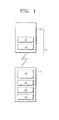
- FIG. 1 is a diagram schematically illustrating a terminal system according an embodiment of the present invention
- FIG.2 is a diagram illustrating an example in which the terminal system of FIG. 1 is used;
- FIG. 3 illustrates a bent second terminal of FIG. 1 ;
- FIG. 4 illustrates a flat second terminal of FIG. 1 ;
- FIG. 5 is a cross-sectional view illustrating an example of a display unit of the second terminal
- FIG. 6 is a cross-sectional view illustrating another example of the display unit of the second terminal.
- FIG. 7 is a cross-sectional view illustrating another example of the display unit of the second terminal.
- FIG. 8 is a cross-sectional view illustrating another example of the display unit of the second terminal.
- FIG. 1 is a diagram schematically illustrating a terminal system 30 according to an embodiment of the present invention.
- the terminal system 30 includes a first terminal 10 and a second terminal 20.
- the first terminal 10 and the second terminal 20 are separated and spaced apart from each other.
- the first and second terminals are coupled (e.g., connected) to each other over a wireless local area network such as a Bluetooth (Bluetooth is a registered trademark of Bluetooth Sig, Inc., a Delaware Corporation) network. Further details are described below.
- Bluetooth Bluetooth is a registered trademark of Bluetooth Sig, Inc., a Delaware Corporation
- the first terminal 10 includes a first control unit 11 and a first communication unit 12. Although in FIG. 1 , the first control unit 11 and the first communication unit 12 are separated from each other, the present invention is not limited thereto. That is, the first control unit 11 and the first communication unit 12 may be integrated. As illustrated in FIG. 2 , the first terminal 10 may be a mobile phone, in particular, a smartphone. The first control unit 11 controls the first communication unit 12 so that the first terminal 10 and the second terminal 20 communicate with each other, further details of which are included below.
- the second terminal 20 includes a second control unit 21, a second communication unit 22, a transformation sensing unit 23, and a display unit 24.
- the second terminal 20 is flexible so that it may be bent and/or folded according to a user's convenience. As a detailed example, as illustrated in FIG. 2 , the second terminal 20 may be worn on a user's wrist in the form of a band.
- the present invention is not limited thereto, and the second terminal 20 having flexibility may be worn on any portion of the body, be attached to clothing, and may also be fixed to a portion of a bicycle or other device. That is, the second terminal 20 is formed to be fixed to a portion of the body, a portion of clothing, or a portion of a bicycle or other sports equipment so that a user may easily check the display unit 24 while riding a bicycle as illustrated in FIG. 2 or doing other types of exercise.
- the transformation sensing unit 23 senses the extent of transformation (e.g., the extent of bending and/or folding) when the second terminal 20 is transformed by bending or folding thereof while, for example, wearing the second terminal 20 on a portion of the body, for example, the wrist.
- the transformation sensing unit 23 may include various sensors, and for example, a piezoelectric sensor.
- the second control unit 21 receives information about the extent of transformation of the second terminal 20, which the transformation sensing unit 23 has sensed.
- An operation of the second communication unit 22 is controlled by the second control unit 21. That is, when the second control unit 21 determines that the second terminal 20 has been transformed by a set or predetermined amount (e.g., a reference amount or first amount) through information received from the transformation sensing unit 23, the second control unit 21 allows the second communication unit 22 and the first communication unit 12 to be coupled (e.g., connected) to each other over a local area wireless communication network and to transmit and receive information between them.
- a set or predetermined amount e.g., a reference amount or first amount
- the second control unit 21 activates the second communication unit 22 to enable local area wireless communication, for example, Bluetooth communication, as a result of information received from the transformation sensing unit 23.
- the second control unit 21 transmits a signal to the first control unit 11, and the first control unit 11 activates the first communication unit 12 to enable local area wireless communication, for example, Bluetooth communication, as a result of the signal received from the second control unit 21.
- the activated first communication unit 12 and the activated second communication unit 22 may be coupled to each other by the local area wireless communication network and may exchange information with each other. In particular, information may be transmitted from the first terminal 10 to the second terminal 20.
- the second control unit 21 activates the second communication unit 22 to enable local area wireless communication, for example, Bluetooth communication, as a result of information received from the transformation sensing unit 23.
- the second communication unit 22 then transmits a signal to the first control unit 11 by using the local area wireless communication, and the first control unit 11 activates the first communication unit 12 to enable local area wireless communication, for example, Bluetooth communication, as a result of the signal received from the second communication unit 22.
- the first control unit 11 controls the first communication unit 12 to transmit predetermined or set information, selected in advance, from the first communication unit 12 to the second communication unit 22.
- the first control unit 11 also activates the first communication unit 12 to enable local area wireless communication when receiving a signal from the second control unit 21 or the second communication unit 22 as described above.
- information that is transmitted from the first communication unit 12 to the second communication unit 22 may be text messages received by the first terminal 10, and may be the current covered distance or travelling time of a user, which has been measured by the first terminal 10.
- the first terminal 10 when it is a smartphone, it may include various applications for checking a body condition of a user.
- the first terminal 10 may obtain information of a user through the various applications, and may transmit the information from the first communication unit 12 to the second communication unit 22.
- the display unit 24 displays information of the first terminal 10 received through communication between the first communication unit 12 and the second communication unit 22. That is, the display unit 24 displays, for example, text messages received by the first terminal 10 or various information of a user, which has been measured by the first terminal 10.
- the second control unit 21 controls the display unit 24 so that the display unit 24 may appropriately display information which the second communication unit 22 has received from the first communication unit 12.
- the display unit 24 may display information generated by the second terminal 20 according to information sensed by the transformation sensing unit 23. That is, when the extent of transformation of the second terminal 20, which the transformation sensing unit 23 has sensed, is smaller than a predetermined or set amount (e.g., a reference amount), brief information generated by the second terminal 20, instead of information of the first terminal 10, may be displayed. Further details are described below.
- a predetermined or set amount e.g., a reference amount
- FIG. 3 illustrates a bent second terminal 20.
- FIG. 3 illustrates a form of the second terminal 20 when a user is wearing the second terminal 20 on the wrist as illustrated in FIG. 2 .
- the transformation sensing unit 23 of the second terminal 20 senses a bend of the second terminal 20 and transmits information about a sensed result to the second control unit 21.
- the second control unit 21 determines that the second terminal 20 has been bent by a predetermined or set amount (e.g., a reference amount), through the information sensed by the transformation sensing unit 23, and activates the second communication unit 22 to enable a local area wireless connection (e.g., Bluetooth communication).
- a predetermined or set amount e.g., a reference amount
- the second control unit 21 transmits a signal to the first control unit 11 according to the information about the sensed result.
- the second communication unit 22 activated by the second control unit 21 may transmit the signal to the first control unit 11 (instead of the second control unit 21).
- the first control unit 11 that has received the signal from the second control unit 21 or the second communication unit 22 activates the first communication unit 12 to enable local area wireless communication between the first communication unit 12 and the second communication unit 22.
- the first terminal 10 may be a mobile phone such as a smartphone, and the first terminal 10 may transmit a received text message to the second terminal 20.
- the first terminal 10 may measure a covered distance and/or a travelling time at a specific point in time and may transmit the measured distance and time to the second terminal 20.
- the first terminal 10 may measure the covered distance and the travelling time by including an application for providing a GPS function.
- the second control unit 21 that controls the second communication unit 22 and the display unit 24 makes the display unit 24 display the information of the first terminal 10 in an appropriate form. That is, as a detailed example, as illustrated in FIG. 3 , the text message received by the first terminal 10 is displayed on an upper side of the display unit 24, and the covered distance and travelling time measured by the first terminal 10 is displayed on a lower side of the display unit 24.
- the first terminal 10 may acquire various information and may process the acquired information. That is, the first terminal 10 that is a smartphone may acquire various information, for example, call waiting information, traffic volume around the current position of a user, or the like by using software embedded therein, an application downloaded by the user, and/or a separately installed chip. The first terminal 10 may then display some or all of the various information on the display unit 24 of the second terminal 20.
- the second terminal 20 may be lighter, smaller, and more compact. Thus, it may be more convenient and comfortable to wear the second terminal 20 on a portion of the body.
- FIG. 4 illustrates a flat second terminal 20.
- the transformation sensing unit 23 senses the state of the second terminal 20 and transmits information about the sensed state to the second control unit 21, and the second control unit 21 disables a local area wireless communication function of the second communication unit 22.
- the second control unit 21 of the second terminal 20 may generate predetermined or set information, e.g., information such as the current time, that is, e.g., received from a time information chip (not shown) separately disposed in the second terminal 20, and makes the display unit 24 display the information.
- predetermined or set information e.g., information such as the current time, that is, e.g., received from a time information chip (not shown) separately disposed in the second terminal 20, and makes the display unit 24 display the information.
- the second terminal 20 directly displays information thereon (i.e., time), independent of the information of the first terminal 10.
- the second control unit 21 since a local area wireless communication function of the second communication unit 22 of the second terminal 20 is discontinued, the second control unit 21 does not need to transmit a separate signal to the first control unit 11 of the first terminal 10. However, as a selective example, the second control unit 21 may transmit a separate signal to the first control unit 11, and the first control unit 11 may interrupt the local area wireless communication function of the first communication unit 12.
- the first terminal 10 When performing an activity, such as cycling or running, the first terminal 10, such as a smartphone, may be stored in a knapsack (or other bag or purse), and thus, a user may not easily check information of the first terminal 10.
- a user In the terminal system 30 according to the current embodiment, a user may also check desired information through the second terminal 20.
- the second terminal 20 is formed to have a form of a flexible band that is easily worn on a portion of the body of a user, for example, the wrist, thereby improving user convenience.
- the second terminal 20 communicates with the first terminal 10 when the second terminal 20 has been transformed.
- the second terminal is worn on the wrist of a user and thus the user may be able to substantially check only the second terminal 20.
- a communication function between the first terminal 10 and the second terminal 20 is deactivated when the second terminal 20 has not been transformed (e.g., is flat), that is, when the user is not wearing the second terminal 20, and thus is not checking the second terminal 20.
- the terminal system 30 may be optimized.
- the efficiency of electrical power use of the first and second terminals 10 and 20 may be improved through an efficient operation of the first and second terminals 10 and 20.
- the second terminal 20 does not generate complicated information but generates only simple information, it is relatively easy to make the second terminal 20 smaller and more compact, and thus, it is possible to increase the ways to wear the second terminal 20 and to improve design flexibility of the second terminal 20.
- the display unit 24 may also have a certain flexibility.
- the second terminal 20 may include various forms of display units in which information is displayed (and be visually recognized by a user). A detailed example of the display unit 24 is described below.
- FIG. 5 is a cross-sectional view illustrating an example of the display unit 24 of the second terminal 20.
- the display unit 24 includes a first electrode 110, an intermediate layer 114, and a second electrode 115 on a substrate 201.
- the substrate 201 is formed of a flexible material.
- the substrate 201 may be formed of a transparent plastic material or any other suitable flexible substrate material.
- the first electrode 110 is formed on the substrate 201.
- the first electrode 110 may include a material such as indium tin oxide (ITO), indium zinc oxide (IZO), ZnO, or In 2 O 3 .
- the first electrode 110 may further include a reflection film formed of Ag, Mg, Al, Pt, Pd, Au, Ni, Nd, Ir, Cr, Li, Yb, and/or Ca.
- a buffer layer (not shown) may be formed between the substrate 201 and the first electrode 110.
- the buffer layer prevents impurities (e.g., undesirable elements) from entering into the substrate 201 and provides a flat surface on the substrate 201.
- the buffer layer may be formed by using one of various materials capable of performing the aforementioned functions.
- the buffer layer may include inorganic materials such as silicon oxide, silicon nitride, silicon oxynitride, aluminum oxide, aluminum nitride, titanium oxide, titanium nitride, and/or the like; organic materials such as polyimides, polyesters, compounds containing an acryl group, and/or the like; or may be a stacked structure including multiple layers, each layer optionally including one or more of the aforementioned materials.
- inorganic materials such as silicon oxide, silicon nitride, silicon oxynitride, aluminum oxide, aluminum nitride, titanium oxide, titanium nitride, and/or the like
- organic materials such as polyimides, polyesters, compounds containing an acryl group, and/or the like
- each layer optionally including one or more of the aforementioned materials.
- the intermediate layer 114 is formed on the first electrode 110.
- the intermediate layer 114 includes an organic emission layer to form visible light.
- the intermediate layer 114 may be formed as a low-molecular weight organic layer or a high-molecular weight organic layer.
- the intermediate layer 114 may include a hole injection layer (HIL), a hole transport layer (HTL), an organic emission layer, an electron transport layer (ETL), an electron injection layer (EIL), and the like.
- the HIL may be formed of a phthalocyanine compound such as copper phthalocyanine, a star-burst type amine such as tris(4-carbazoyl-9-ylphenyl)amine (TCTA), 4,4',4"-Tris(N-3-methylphenyl-N-phenylamino)triphenylamine (m-MTDATA), and/or 1,3,5-tris[4-(3-metylphenylphenylamino)phenyl]benzene (m-MTDAPB), and/or the like.
- TCTA tris(4-carbazoyl-9-ylphenyl)amine
- m-MTDATA 4,4',4"-Tris(N-3-methylphenyl-N-phenylamino)triphenylamine
- m-MTDAPB 1,3,5-tris[4-(3-metylphenylphenylamino)phenyl]benzene
- the HTL may be formed of N,N'-bis(3-methylphenyl)-N,N'-diphenyl-[1,1-biphenyl]-4,4'-diamine (TPD), N,N'-di(naphthalene-1-yl)-N,N'-diphenyl benzidine ( ⁇ -NPD), and/or the like.
- TPD N,N'-bis(3-methylphenyl)-N,N'-diphenyl-[1,1-biphenyl]-4,4'-diamine
- ⁇ -NPD N,N'-di(naphthalene-1-yl)-N,N'-diphenyl benzidine
- the EIL may be formed of a material such as LiF, NaCl, CsF, Li 2 O, BaO, lithium quinolate (Liq), and/or the like.
- the ETL may be formed of Alq 3 and/or the like.
- the organic emission layer may include a host material and a dopant material.
- the host material of the organic emission layer may be tris(8-hydroxy-quinolinato)aluminum (Alq 3 ), 9,10-di(naphth-2-yl)anthracene (ADN), 3-tert-butyl-9,10-di(naphth-2-yl)anthracene (TBADN), 4,4'-bis(2,2-diphenyl-ethene-1-yl)-4,4'-dimethylphenyl (DPVBi), 4,4'-bis(2,2-diphenyl-ethene-1-yl)-4,4'-dimethylphenyl (p-DMDPVBi), tert(9,9-diarylfluorene)s (TDAF), 2-(9,9'-spirobifluorene-2-yl)-9,9'-spirobifluorene(BSDF), 2,7-bis(9,9'-spirobifluorene-2-yl)-9,9'-
- Examples of the dopant material of the organic emission layer include 4,4'-bis[4-(di-p-tolylamino)styryl]biphenyl (DPAVBi), 9,10-di(naphth-2-yl)anthracene (ADN), 3-tert-butyl-9,1 0-di(naphth-2-yl)anthracene (TBADN), and/or the like.
- DPAVBi 4,4'-bis[4-(di-p-tolylamino)styryl]biphenyl
- ADN 9,10-di(naphth-2-yl)anthracene
- TAADN 3-tert-butyl-9,1 0-di(naphth-2-yl)anthracene
- the second electrode 115 is formed on the intermediate layer 114.
- the second electrode 115 may be formed of a metal such as Ag, Mg, Al, Pt, Pd, Au, Ni, Nd, Ir, Cr, Li, and/or Ca.
- FIG. 6 is a cross-sectional view illustrating another example of the display unit 24 of the second terminal 20.
- the display unit 24 includes a first electrode 210, a pixel-defining layer 219, an intermediate layer 214, and a second electrode 215 on a substrate 201.
- a configuration of each element will be described in detail. For convenience of description, mainly the differences from the above example will now be described.
- the first electrode 210 is formed on the substrate 201.
- the pixel-defining layer 219 is formed on the first electrode 210 by using an insulation material.
- the pixel-defining layer 219 has an opening to expose an upper surface of the first electrode 210.
- the intermediate layer 214 is formed on the exposed upper surface of the first electrode 210.
- the intermediate layer 214 includes an organic emission layer to emit visible light.
- the second electrode 215 is formed on the intermediate layer 214.
- FIG. 7 is a cross-sectional view illustrating another example of the display unit 24 of the second terminal 20.
- the display unit 24 includes a thin film transistor TFT formed on a substrate 301.
- the TFT includes an active layer 303, a gate electrode 305, a source electrode 307, and a drain electrode 308.
- a buffer layer 302 may optionally be formed on the substrate 301.
- the active layer 303 having a predetermined or set pattern (e.g., a first pattern) is formed on the buffer layer 302.
- the active layer 303 may be formed of an inorganic semiconductor, such as amorphous silicon or polysilicon, or an organic semiconductor.
- the active layer 303 includes a source area, a drain area, and a channel area.
- the source and drain areas of the active layer 303 may be formed by doping the active layer 303 with Group III and/or Group V impurities after the active layer 303 is formed of amorphous silicon or polysilicon.
- a gate insulation film 304 is formed on the active layer 303, and the gate electrode 305 is formed on a predetermined or set area (e.g., a first area) of the gate insulation film 304.
- the gate insulation film 304 insulates the gate electrode 305 from the active layer 303 and may be formed of an organic material or an inorganic material, such as SiNx and/or SiO 2 .
- the gate electrode 305 may include Au, Ag, Cu, Ni, Pt, Pd, Al, Mo, and/or an alloy, and may be an Al:Nd alloy or a Mo:W alloy.
- the material for forming the gate electrode 305 is not limited thereto, and various other materials may also be used to form the gate electrode 305 in consideration of adhesion with respect to an adjacent layer, planarization, electric resistance, and/or processability.
- An interlayer dielectric 317 is formed on the gate electrode 305.
- the interlayer dielectric 317 and the gate insulation film 304 are formed to expose the source and drain areas of the active layer 303.
- the source electrode 307 and the drain electrode 308 are formed to contact respective exposed source and drain areas of the active layer 303.
- the source electrode 307 and the drain electrode 308 may each be formed of any one of various conductive materials and may have a single-layer or multi-layer structure.
- a passivation layer 318 is formed on the TFT.
- the passivation layer 318 is formed on the source electrode 307 and the drain electrode 308.
- the passivation layer 318 is formed to expose a predetermined or set area (e.g., a first area) of the drain electrode 308 by not covering the whole drain electrode 308.
- a first electrode 310 is formed to be coupled (e.g. connected) to the exposed portion of the drain electrode 308.
- a pixel-defining film 319 is formed of an insulating material on the first electrode 310.
- the pixel-defining film 319 is formed to expose a predetermined or set area (e.g., a first area) of the first electrode 310.
- An intermediate layer 314 is formed to be coupled (e.g. connected) to the exposed portion of the first electrode 310.
- a second electrode 315 is formed to be coupled (e.g. connected) to the intermediate layer 314.
- a sealing element (not shown) may be disposed on the second electrode 315.
- the sealing element may be formed to protect the intermediate layer 314 and other layers from external humidity and/or oxygen.
- the sealing element may include plastic or may have a multi-layer structure of alternating organic material and inorganic material.
- FIG. 8 is a cross-sectional view illustrating another example of the display unit 24 of the second terminal 20.
- the display unit 24 includes a capacitor 418 and a thin film transistor TFT formed on a substrate 401.
- the TFT includes an active layer 403, a gate electrode 405, a source electrode 407, and a drain electrode 408.
- a buffer layer 402 is formed on the substrate 401.
- the active layer 403 having a predetermined or set area e.g., a first area
- a first capacitor electrode 411 is formed on the buffer layer 402.
- the first capacitor electrode 411 may be formed of the same material as the active layer 403.
- a gate insulating layer 404 is formed on the buffer layer 402 to cover the active layer 403 and the first capacitor electrode 411.
- the gate electrode 405, a first electrode 410, and a second capacitor electrode 413 are formed on the gate insulating layer 404.
- the gate electrode 405 includes a first conductive layer 405a and a second conductive layer 405b.
- the first electrode 410 may be formed of the same material as the first conductive layer 405a.
- a conductive portion 410a is disposed on a predetermined upper portion of the first electrode 410.
- the conductive portion 410a may be formed of the same material as the second conductive layer 405b.
- the second capacitor electrode 413 includes a first layer 413a and a second layer 413b.
- the first layer 413a may be formed of the same material as the first conductive layer 405a
- the second layer 413b may be formed of the same material as the second conductive layer 405b.
- the second layer 413b is formed on the first layer 413a to be smaller than the first layer 413a.
- the second capacitor electrode 413 overlaps with the first capacitor electrode 411, and is smaller than the first capacitor electrode 411.
- An interlayer dielectric 417 is formed on the first electrode 410, the gate electrode 405, and the second capacitor electrode 413.
- the source electrode 407 and the drain electrode 408 are formed on the interlayer dielectric 417 and are coupled (e.g. connected) to the active layer 403.
- one of the source electrode 407 and the drain electrode 408 is electrically coupled (e.g. connected) to the first electrode 410.
- FIG. 8 shows that the drain electrode 408 is electrically coupled to the first electrode 410.
- the drain electrode 408 contacts the active layer 403 and the conductive portion 410a.
- a pixel-defining layer 419 is formed on the interlayer dielectric 417 to cover the source electrode 407, the drain electrode 408, and the capacitor 418.
- the pixel-defining layer 419 includes an opening 419a that corresponds to an upper surface of the first electrode 410, and an intermediate layer 414 is formed on the first electrode 410 that is exposed through the opening 419a of the pixel-defining layer 419.
- a second electrode 415 is formed on the intermediate layer 414.
- a sealing element (not shown) may be disposed on the second electrode 415.
- the sealing element may be formed to prevent damage to the first electrode 410, the intermediate layer 414, or the second electrode 415 by external foreign bodies or shock.
- the sealing element may be formed by using glass, a thin metal film, or the like, or it may have a stacked structure, each layer formed of an organic material and/or an inorganic material.
- the display unit 24 of the second terminal 20 may be a liquid crystal device or any other suitable display device.
Landscapes
- Engineering & Computer Science (AREA)
- Theoretical Computer Science (AREA)
- General Engineering & Computer Science (AREA)
- Physics & Mathematics (AREA)
- General Physics & Mathematics (AREA)
- Human Computer Interaction (AREA)
- Computer Hardware Design (AREA)
- Signal Processing (AREA)
- Computer Networks & Wireless Communication (AREA)
- Telephone Function (AREA)
- Devices For Indicating Variable Information By Combining Individual Elements (AREA)
- Electroluminescent Light Sources (AREA)
- Telephone Set Structure (AREA)
Applications Claiming Priority (1)
| Application Number | Priority Date | Filing Date | Title |
|---|---|---|---|
| KR1020120065616A KR101971200B1 (ko) | 2012-06-19 | 2012-06-19 | 단말기 시스템 및 플렉시블 단말기 |
Publications (2)
| Publication Number | Publication Date |
|---|---|
| EP2677395A1 true EP2677395A1 (fr) | 2013-12-25 |
| EP2677395B1 EP2677395B1 (fr) | 2018-10-24 |
Family
ID=47739003
Family Applications (1)
| Application Number | Title | Priority Date | Filing Date |
|---|---|---|---|
| EP13151759.1A Active EP2677395B1 (fr) | 2012-06-19 | 2013-01-18 | Système de terminal et terminal souple |
Country Status (6)
| Country | Link |
|---|---|
| US (1) | US9395815B2 (fr) |
| EP (1) | EP2677395B1 (fr) |
| JP (1) | JP6278617B2 (fr) |
| KR (1) | KR101971200B1 (fr) |
| CN (2) | CN103516890B (fr) |
| TW (1) | TWI604713B (fr) |
Cited By (1)
| Publication number | Priority date | Publication date | Assignee | Title |
|---|---|---|---|---|
| WO2015107386A1 (fr) * | 2014-01-15 | 2015-07-23 | Sony Corporation | Notification haptique sur des articles portables sur soi |
Families Citing this family (7)
| Publication number | Priority date | Publication date | Assignee | Title |
|---|---|---|---|---|
| KR101971200B1 (ko) * | 2012-06-19 | 2019-04-23 | 삼성디스플레이 주식회사 | 단말기 시스템 및 플렉시블 단말기 |
| JP6264499B2 (ja) | 2015-02-27 | 2018-01-24 | 株式会社村田製作所 | Rfモジュール及びrfシステム |
| US10386941B2 (en) * | 2015-06-16 | 2019-08-20 | Intel Corporation | Gyratory sensing system to enhance wearable device user experience via HMI extension |
| US9787346B2 (en) * | 2016-01-28 | 2017-10-10 | Motorola Mobility Llc | Configurable wearable electronic device |
| CN108684025B (zh) * | 2018-04-28 | 2021-09-21 | 努比亚技术有限公司 | 一种数据传输方法、可折叠终端及计算机可读存储介质 |
| CN109547619B (zh) * | 2018-11-28 | 2020-09-04 | 三星电子(中国)研发中心 | 一种基于柔性屏幕的检测建立设备间连接的方法、装置及系统 |
| WO2023008911A1 (fr) * | 2021-07-30 | 2023-02-02 | 삼성전자 주식회사 | Dispositif électronique et son procédé de commande de communication |
Citations (2)
| Publication number | Priority date | Publication date | Assignee | Title |
|---|---|---|---|---|
| EP2192750A2 (fr) * | 2008-11-10 | 2010-06-02 | Lg Electronics Inc. | Terminal mobile utilisant un affichage flexible et procédé de contrôle du terminal mobile |
| EP2365530A2 (fr) * | 2010-03-09 | 2011-09-14 | Samsung Mobile Display Co., Ltd. | Appareil à affichage électroluminescent organique |
Family Cites Families (22)
| Publication number | Priority date | Publication date | Assignee | Title |
|---|---|---|---|---|
| JP2002116905A (ja) * | 2000-10-06 | 2002-04-19 | Matsushita Electric Ind Co Ltd | 情報処理装置 |
| JP4434609B2 (ja) * | 2002-03-29 | 2010-03-17 | 株式会社東芝 | 表示入力システム |
| US7456823B2 (en) * | 2002-06-14 | 2008-11-25 | Sony Corporation | User interface apparatus and portable information apparatus |
| US7557369B2 (en) * | 2004-07-29 | 2009-07-07 | Samsung Mobile Display Co., Ltd. | Display and method for manufacturing the same |
| KR20060019869A (ko) | 2004-08-30 | 2006-03-06 | 삼성전자주식회사 | 필름형 압박 센서를 통한 운동량 측정 장치 및 그 방법 |
| DE102004050907A1 (de) * | 2004-10-19 | 2006-04-27 | Siemens Ag | Gestaltungselement für ein Bedienfeld einer Vorrichtung |
| CN101247610B (zh) * | 2007-02-13 | 2012-03-28 | 艾威梯科技(北京)有限公司 | 管理多种短距离无线技术通信的方法、设备及系统 |
| KR100875101B1 (ko) * | 2007-08-08 | 2008-12-19 | 삼성모바일디스플레이주식회사 | 유기 발광 표시장치 및 유기 발광 표시장치의 제조방법 |
| KR101507786B1 (ko) * | 2008-03-31 | 2015-04-03 | 엘지전자 주식회사 | 단말기 및 이것의 간섭 개선 방법 |
| US20100011291A1 (en) | 2008-07-10 | 2010-01-14 | Nokia Corporation | User interface, device and method for a physically flexible device |
| US7953462B2 (en) * | 2008-08-04 | 2011-05-31 | Vartanian Harry | Apparatus and method for providing an adaptively responsive flexible display device |
| KR101495178B1 (ko) * | 2008-09-25 | 2015-02-24 | 엘지전자 주식회사 | 이동 단말기 및 이동 단말기의 무선 인터넷 접속 방법 |
| KR101139297B1 (ko) | 2008-09-27 | 2012-04-26 | 정세린 | 블루투스 시계 및 그의 제어방법 |
| WO2010046732A1 (fr) * | 2008-10-24 | 2010-04-29 | Nokia Corporation | Sélection de fonctions dans une communication sans fil |
| JP2010250708A (ja) * | 2009-04-17 | 2010-11-04 | Toshiba Corp | 手袋型携帯端末 |
| TWI401600B (zh) * | 2009-05-11 | 2013-07-11 | Compal Electronics Inc | 管理無線通訊元件功能的方法及使用者介面裝置 |
| WO2012061438A2 (fr) | 2010-11-01 | 2012-05-10 | Nike International Ltd. | Ensemble de dispositif pouvant être porté ayant une fonction athlétique |
| CN102413235A (zh) * | 2011-11-02 | 2012-04-11 | 中兴通讯股份有限公司 | 移动终端以及利用该移动终端进行信息显示的方法 |
| US20130201215A1 (en) * | 2012-02-03 | 2013-08-08 | John A. MARTELLARO | Accessing applications in a mobile augmented reality environment |
| US9411423B2 (en) * | 2012-02-08 | 2016-08-09 | Immersion Corporation | Method and apparatus for haptic flex gesturing |
| US9186077B2 (en) * | 2012-02-16 | 2015-11-17 | Google Technology Holdings LLC | Method and device with customizable power management |
| KR101971200B1 (ko) * | 2012-06-19 | 2019-04-23 | 삼성디스플레이 주식회사 | 단말기 시스템 및 플렉시블 단말기 |
-
2012
- 2012-06-19 KR KR1020120065616A patent/KR101971200B1/ko active IP Right Grant
- 2012-10-10 US US13/648,743 patent/US9395815B2/en active Active
- 2012-11-06 TW TW101141069A patent/TWI604713B/zh active
-
2013
- 2013-01-18 EP EP13151759.1A patent/EP2677395B1/fr active Active
- 2013-01-25 CN CN201310029591.0A patent/CN103516890B/zh active Active
- 2013-01-25 CN CN201320041248.3U patent/CN203445928U/zh not_active Withdrawn - After Issue
- 2013-06-10 JP JP2013121759A patent/JP6278617B2/ja active Active
Patent Citations (2)
| Publication number | Priority date | Publication date | Assignee | Title |
|---|---|---|---|---|
| EP2192750A2 (fr) * | 2008-11-10 | 2010-06-02 | Lg Electronics Inc. | Terminal mobile utilisant un affichage flexible et procédé de contrôle du terminal mobile |
| EP2365530A2 (fr) * | 2010-03-09 | 2011-09-14 | Samsung Mobile Display Co., Ltd. | Appareil à affichage électroluminescent organique |
Cited By (2)
| Publication number | Priority date | Publication date | Assignee | Title |
|---|---|---|---|---|
| WO2015107386A1 (fr) * | 2014-01-15 | 2015-07-23 | Sony Corporation | Notification haptique sur des articles portables sur soi |
| US9392094B2 (en) | 2014-01-15 | 2016-07-12 | Sony Corporation | Mobile electronic wearable device and method for providing haptic notification |
Also Published As
| Publication number | Publication date |
|---|---|
| EP2677395B1 (fr) | 2018-10-24 |
| CN103516890B (zh) | 2017-10-31 |
| US9395815B2 (en) | 2016-07-19 |
| CN103516890A (zh) | 2014-01-15 |
| KR101971200B1 (ko) | 2019-04-23 |
| US20130336304A1 (en) | 2013-12-19 |
| KR20130142413A (ko) | 2013-12-30 |
| CN203445928U (zh) | 2014-02-19 |
| TW201401836A (zh) | 2014-01-01 |
| JP2014003604A (ja) | 2014-01-09 |
| TWI604713B (zh) | 2017-11-01 |
| JP6278617B2 (ja) | 2018-02-14 |
Similar Documents
| Publication | Publication Date | Title |
|---|---|---|
| EP2677395B1 (fr) | Système de terminal et terminal souple | |
| EP2608288B1 (fr) | Appareil à affichage luminescent organique et son procédé de fabrication | |
| US10056575B2 (en) | Flexible display apparatus, organic light emitting display apparatus, and mother substrate for flexible display apparatus | |
| US9761647B2 (en) | Organic light emitting display device and method of manufacturing the same | |
| US8193017B2 (en) | Organic light emitting display device and method of manufacturing the same | |
| KR102085320B1 (ko) | 유기 발광 표시 장치 | |
| TWI584451B (zh) | 顯示基板與其製造方法 | |
| US9142162B2 (en) | Flexible display apparatus that adjusts image size and resolution according to folding thereof | |
| TWI549284B (zh) | 有機發光顯示裝置及其製造方法 | |
| US20110204342A1 (en) | Organic light-emitting display device and method of manufacturing the same | |
| US8994703B2 (en) | Display apparatus having bimetal element which can be controllably bent | |
| US8860015B2 (en) | Organic light emitting display apparatus and method of manufacturing the same | |
| KR20140046331A (ko) | 유기 발광 표시 장치 및 유기 발광 표시 장치 제조 방법 | |
| US9461263B2 (en) | Organic light emitting display apparatus and method of manufacturing the same | |
| US20140014914A1 (en) | Organic light-emitting display device and method of manufacturing the same | |
| US20140014908A1 (en) | Display apparatus and method of manufacturing the same | |
| CN111799309A (zh) | 压敏显示装置 |
Legal Events
| Date | Code | Title | Description |
|---|---|---|---|
| PUAI | Public reference made under article 153(3) epc to a published international application that has entered the european phase |
Free format text: ORIGINAL CODE: 0009012 |
|
| AK | Designated contracting states |
Kind code of ref document: A1 Designated state(s): AL AT BE BG CH CY CZ DE DK EE ES FI FR GB GR HR HU IE IS IT LI LT LU LV MC MK MT NL NO PL PT RO RS SE SI SK SM TR |
|
| AX | Request for extension of the european patent |
Extension state: BA ME |
|
| 17P | Request for examination filed |
Effective date: 20140213 |
|
| RBV | Designated contracting states (corrected) |
Designated state(s): AL AT BE BG CH CY CZ DE DK EE ES FI FR GB GR HR HU IE IS IT LI LT LU LV MC MK MT NL NO PL PT RO RS SE SI SK SM TR |
|
| RAP1 | Party data changed (applicant data changed or rights of an application transferred) |
Owner name: SAMSUNG DISPLAY CO., LTD. |
|
| 17Q | First examination report despatched |
Effective date: 20160603 |
|
| STAA | Information on the status of an ep patent application or granted ep patent |
Free format text: STATUS: EXAMINATION IS IN PROGRESS |
|
| GRAP | Despatch of communication of intention to grant a patent |
Free format text: ORIGINAL CODE: EPIDOSNIGR1 |
|
| STAA | Information on the status of an ep patent application or granted ep patent |
Free format text: STATUS: GRANT OF PATENT IS INTENDED |
|
| RIC1 | Information provided on ipc code assigned before grant |
Ipc: G06F 3/01 20060101AFI20180419BHEP Ipc: H04B 1/3827 20150101ALN20180419BHEP Ipc: G06F 1/16 20060101ALI20180419BHEP Ipc: G06F 3/0362 20130101ALI20180419BHEP Ipc: H04M 1/725 20060101ALN20180419BHEP Ipc: H04M 1/02 20060101ALI20180419BHEP Ipc: G06F 3/0487 20130101ALI20180419BHEP |
|
| RIC1 | Information provided on ipc code assigned before grant |
Ipc: G06F 3/0362 20130101ALI20180426BHEP Ipc: H04B 1/3827 20150101ALN20180426BHEP Ipc: H04M 1/02 20060101ALI20180426BHEP Ipc: G06F 3/01 20060101AFI20180426BHEP Ipc: G06F 1/16 20060101ALI20180426BHEP Ipc: G06F 3/0487 20130101ALI20180426BHEP Ipc: H04M 1/725 20060101ALN20180426BHEP |
|
| INTG | Intention to grant announced |
Effective date: 20180518 |
|
| RIC1 | Information provided on ipc code assigned before grant |
Ipc: H04M 1/725 20060101ALN20180507BHEP Ipc: G06F 3/0362 20130101ALI20180507BHEP Ipc: G06F 3/0487 20130101ALI20180507BHEP Ipc: H04B 1/3827 20150101ALN20180507BHEP Ipc: G06F 1/16 20060101ALI20180507BHEP Ipc: G06F 3/01 20060101AFI20180507BHEP Ipc: H04M 1/02 20060101ALI20180507BHEP |
|
| GRAS | Grant fee paid |
Free format text: ORIGINAL CODE: EPIDOSNIGR3 |
|
| GRAA | (expected) grant |
Free format text: ORIGINAL CODE: 0009210 |
|
| STAA | Information on the status of an ep patent application or granted ep patent |
Free format text: STATUS: THE PATENT HAS BEEN GRANTED |
|
| AK | Designated contracting states |
Kind code of ref document: B1 Designated state(s): AL AT BE BG CH CY CZ DE DK EE ES FI FR GB GR HR HU IE IS IT LI LT LU LV MC MK MT NL NO PL PT RO RS SE SI SK SM TR |
|
| REG | Reference to a national code |
Ref country code: CH Ref legal event code: EP |
|
| REG | Reference to a national code |
Ref country code: IE Ref legal event code: FG4D |
|
| REG | Reference to a national code |
Ref country code: AT Ref legal event code: REF Ref document number: 1057433 Country of ref document: AT Kind code of ref document: T Effective date: 20181115 |
|
| REG | Reference to a national code |
Ref country code: DE Ref legal event code: R096 Ref document number: 602013045435 Country of ref document: DE |
|
| REG | Reference to a national code |
Ref country code: NL Ref legal event code: FP |
|
| REG | Reference to a national code |
Ref country code: LT Ref legal event code: MG4D |
|
| REG | Reference to a national code |
Ref country code: AT Ref legal event code: MK05 Ref document number: 1057433 Country of ref document: AT Kind code of ref document: T Effective date: 20181024 |
|
| PG25 | Lapsed in a contracting state [announced via postgrant information from national office to epo] |
Ref country code: IS Free format text: LAPSE BECAUSE OF FAILURE TO SUBMIT A TRANSLATION OF THE DESCRIPTION OR TO PAY THE FEE WITHIN THE PRESCRIBED TIME-LIMIT Effective date: 20190224 Ref country code: FI Free format text: LAPSE BECAUSE OF FAILURE TO SUBMIT A TRANSLATION OF THE DESCRIPTION OR TO PAY THE FEE WITHIN THE PRESCRIBED TIME-LIMIT Effective date: 20181024 Ref country code: AT Free format text: LAPSE BECAUSE OF FAILURE TO SUBMIT A TRANSLATION OF THE DESCRIPTION OR TO PAY THE FEE WITHIN THE PRESCRIBED TIME-LIMIT Effective date: 20181024 Ref country code: LV Free format text: LAPSE BECAUSE OF FAILURE TO SUBMIT A TRANSLATION OF THE DESCRIPTION OR TO PAY THE FEE WITHIN THE PRESCRIBED TIME-LIMIT Effective date: 20181024 Ref country code: LT Free format text: LAPSE BECAUSE OF FAILURE TO SUBMIT A TRANSLATION OF THE DESCRIPTION OR TO PAY THE FEE WITHIN THE PRESCRIBED TIME-LIMIT Effective date: 20181024 Ref country code: NO Free format text: LAPSE BECAUSE OF FAILURE TO SUBMIT A TRANSLATION OF THE DESCRIPTION OR TO PAY THE FEE WITHIN THE PRESCRIBED TIME-LIMIT Effective date: 20190124 Ref country code: HR Free format text: LAPSE BECAUSE OF FAILURE TO SUBMIT A TRANSLATION OF THE DESCRIPTION OR TO PAY THE FEE WITHIN THE PRESCRIBED TIME-LIMIT Effective date: 20181024 Ref country code: PL Free format text: LAPSE BECAUSE OF FAILURE TO SUBMIT A TRANSLATION OF THE DESCRIPTION OR TO PAY THE FEE WITHIN THE PRESCRIBED TIME-LIMIT Effective date: 20181024 Ref country code: BG Free format text: LAPSE BECAUSE OF FAILURE TO SUBMIT A TRANSLATION OF THE DESCRIPTION OR TO PAY THE FEE WITHIN THE PRESCRIBED TIME-LIMIT Effective date: 20190124 Ref country code: ES Free format text: LAPSE BECAUSE OF FAILURE TO SUBMIT A TRANSLATION OF THE DESCRIPTION OR TO PAY THE FEE WITHIN THE PRESCRIBED TIME-LIMIT Effective date: 20181024 |
|
| PG25 | Lapsed in a contracting state [announced via postgrant information from national office to epo] |
Ref country code: PT Free format text: LAPSE BECAUSE OF FAILURE TO SUBMIT A TRANSLATION OF THE DESCRIPTION OR TO PAY THE FEE WITHIN THE PRESCRIBED TIME-LIMIT Effective date: 20190224 Ref country code: AL Free format text: LAPSE BECAUSE OF FAILURE TO SUBMIT A TRANSLATION OF THE DESCRIPTION OR TO PAY THE FEE WITHIN THE PRESCRIBED TIME-LIMIT Effective date: 20181024 Ref country code: SE Free format text: LAPSE BECAUSE OF FAILURE TO SUBMIT A TRANSLATION OF THE DESCRIPTION OR TO PAY THE FEE WITHIN THE PRESCRIBED TIME-LIMIT Effective date: 20181024 Ref country code: GR Free format text: LAPSE BECAUSE OF FAILURE TO SUBMIT A TRANSLATION OF THE DESCRIPTION OR TO PAY THE FEE WITHIN THE PRESCRIBED TIME-LIMIT Effective date: 20190125 Ref country code: RS Free format text: LAPSE BECAUSE OF FAILURE TO SUBMIT A TRANSLATION OF THE DESCRIPTION OR TO PAY THE FEE WITHIN THE PRESCRIBED TIME-LIMIT Effective date: 20181024 |
|
| REG | Reference to a national code |
Ref country code: DE Ref legal event code: R097 Ref document number: 602013045435 Country of ref document: DE |
|
| PG25 | Lapsed in a contracting state [announced via postgrant information from national office to epo] |
Ref country code: IT Free format text: LAPSE BECAUSE OF FAILURE TO SUBMIT A TRANSLATION OF THE DESCRIPTION OR TO PAY THE FEE WITHIN THE PRESCRIBED TIME-LIMIT Effective date: 20181024 Ref country code: CZ Free format text: LAPSE BECAUSE OF FAILURE TO SUBMIT A TRANSLATION OF THE DESCRIPTION OR TO PAY THE FEE WITHIN THE PRESCRIBED TIME-LIMIT Effective date: 20181024 Ref country code: DK Free format text: LAPSE BECAUSE OF FAILURE TO SUBMIT A TRANSLATION OF THE DESCRIPTION OR TO PAY THE FEE WITHIN THE PRESCRIBED TIME-LIMIT Effective date: 20181024 |
|
| PG25 | Lapsed in a contracting state [announced via postgrant information from national office to epo] |
Ref country code: MC Free format text: LAPSE BECAUSE OF FAILURE TO SUBMIT A TRANSLATION OF THE DESCRIPTION OR TO PAY THE FEE WITHIN THE PRESCRIBED TIME-LIMIT Effective date: 20181024 Ref country code: SM Free format text: LAPSE BECAUSE OF FAILURE TO SUBMIT A TRANSLATION OF THE DESCRIPTION OR TO PAY THE FEE WITHIN THE PRESCRIBED TIME-LIMIT Effective date: 20181024 Ref country code: EE Free format text: LAPSE BECAUSE OF FAILURE TO SUBMIT A TRANSLATION OF THE DESCRIPTION OR TO PAY THE FEE WITHIN THE PRESCRIBED TIME-LIMIT Effective date: 20181024 Ref country code: RO Free format text: LAPSE BECAUSE OF FAILURE TO SUBMIT A TRANSLATION OF THE DESCRIPTION OR TO PAY THE FEE WITHIN THE PRESCRIBED TIME-LIMIT Effective date: 20181024 Ref country code: SK Free format text: LAPSE BECAUSE OF FAILURE TO SUBMIT A TRANSLATION OF THE DESCRIPTION OR TO PAY THE FEE WITHIN THE PRESCRIBED TIME-LIMIT Effective date: 20181024 |
|
| PLBE | No opposition filed within time limit |
Free format text: ORIGINAL CODE: 0009261 |
|
| REG | Reference to a national code |
Ref country code: CH Ref legal event code: PL |
|
| STAA | Information on the status of an ep patent application or granted ep patent |
Free format text: STATUS: NO OPPOSITION FILED WITHIN TIME LIMIT |
|
| PG25 | Lapsed in a contracting state [announced via postgrant information from national office to epo] |
Ref country code: LU Free format text: LAPSE BECAUSE OF NON-PAYMENT OF DUE FEES Effective date: 20190118 |
|
| 26N | No opposition filed |
Effective date: 20190725 |
|
| REG | Reference to a national code |
Ref country code: BE Ref legal event code: MM Effective date: 20190131 |
|
| REG | Reference to a national code |
Ref country code: IE Ref legal event code: MM4A |
|
| PG25 | Lapsed in a contracting state [announced via postgrant information from national office to epo] |
Ref country code: SI Free format text: LAPSE BECAUSE OF FAILURE TO SUBMIT A TRANSLATION OF THE DESCRIPTION OR TO PAY THE FEE WITHIN THE PRESCRIBED TIME-LIMIT Effective date: 20181024 |
|
| PG25 | Lapsed in a contracting state [announced via postgrant information from national office to epo] |
Ref country code: BE Free format text: LAPSE BECAUSE OF NON-PAYMENT OF DUE FEES Effective date: 20190131 |
|
| PG25 | Lapsed in a contracting state [announced via postgrant information from national office to epo] |
Ref country code: CH Free format text: LAPSE BECAUSE OF NON-PAYMENT OF DUE FEES Effective date: 20190131 Ref country code: LI Free format text: LAPSE BECAUSE OF NON-PAYMENT OF DUE FEES Effective date: 20190131 |
|
| PG25 | Lapsed in a contracting state [announced via postgrant information from national office to epo] |
Ref country code: IE Free format text: LAPSE BECAUSE OF NON-PAYMENT OF DUE FEES Effective date: 20190118 |
|
| PG25 | Lapsed in a contracting state [announced via postgrant information from national office to epo] |
Ref country code: TR Free format text: LAPSE BECAUSE OF FAILURE TO SUBMIT A TRANSLATION OF THE DESCRIPTION OR TO PAY THE FEE WITHIN THE PRESCRIBED TIME-LIMIT Effective date: 20181024 |
|
| PG25 | Lapsed in a contracting state [announced via postgrant information from national office to epo] |
Ref country code: MT Free format text: LAPSE BECAUSE OF NON-PAYMENT OF DUE FEES Effective date: 20190118 |
|
| PG25 | Lapsed in a contracting state [announced via postgrant information from national office to epo] |
Ref country code: CY Free format text: LAPSE BECAUSE OF FAILURE TO SUBMIT A TRANSLATION OF THE DESCRIPTION OR TO PAY THE FEE WITHIN THE PRESCRIBED TIME-LIMIT Effective date: 20181024 |
|
| PG25 | Lapsed in a contracting state [announced via postgrant information from national office to epo] |
Ref country code: HU Free format text: LAPSE BECAUSE OF FAILURE TO SUBMIT A TRANSLATION OF THE DESCRIPTION OR TO PAY THE FEE WITHIN THE PRESCRIBED TIME-LIMIT; INVALID AB INITIO Effective date: 20130118 |
|
| PG25 | Lapsed in a contracting state [announced via postgrant information from national office to epo] |
Ref country code: MK Free format text: LAPSE BECAUSE OF FAILURE TO SUBMIT A TRANSLATION OF THE DESCRIPTION OR TO PAY THE FEE WITHIN THE PRESCRIBED TIME-LIMIT Effective date: 20181024 |
|
| P01 | Opt-out of the competence of the unified patent court (upc) registered |
Effective date: 20230515 |
|
| PGFP | Annual fee paid to national office [announced via postgrant information from national office to epo] |
Ref country code: GB Payment date: 20231220 Year of fee payment: 12 |
|
| PGFP | Annual fee paid to national office [announced via postgrant information from national office to epo] |
Ref country code: NL Payment date: 20231221 Year of fee payment: 12 Ref country code: FR Payment date: 20231222 Year of fee payment: 12 |
|
| PGFP | Annual fee paid to national office [announced via postgrant information from national office to epo] |
Ref country code: DE Payment date: 20231220 Year of fee payment: 12 |