EP2677300A2 - Non-dispersive infrared gas sensor with a reflective diffuser - Google Patents
Non-dispersive infrared gas sensor with a reflective diffuser Download PDFInfo
- Publication number
- EP2677300A2 EP2677300A2 EP13172490.8A EP13172490A EP2677300A2 EP 2677300 A2 EP2677300 A2 EP 2677300A2 EP 13172490 A EP13172490 A EP 13172490A EP 2677300 A2 EP2677300 A2 EP 2677300A2
- Authority
- EP
- European Patent Office
- Prior art keywords
- infrared
- gas sensor
- reflective
- dispersive
- waveguide
- Prior art date
- Legal status (The legal status is an assumption and is not a legal conclusion. Google has not performed a legal analysis and makes no representation as to the accuracy of the status listed.)
- Withdrawn
Links
- PXHVJJICTQNCMI-UHFFFAOYSA-N Nickel Chemical compound [Ni] PXHVJJICTQNCMI-UHFFFAOYSA-N 0.000 claims description 10
- 239000011248 coating agent Substances 0.000 claims description 10
- 238000000576 coating method Methods 0.000 claims description 10
- 238000000034 method Methods 0.000 claims description 6
- 229920001169 thermoplastic Polymers 0.000 claims description 6
- 239000004416 thermosoftening plastic Substances 0.000 claims description 6
- PCHJSUWPFVWCPO-UHFFFAOYSA-N gold Chemical compound [Au] PCHJSUWPFVWCPO-UHFFFAOYSA-N 0.000 claims description 5
- 239000010931 gold Substances 0.000 claims description 5
- 229910052737 gold Inorganic materials 0.000 claims description 5
- 238000007654 immersion Methods 0.000 claims description 5
- 229910052759 nickel Inorganic materials 0.000 claims description 5
- 238000004891 communication Methods 0.000 claims description 4
- 230000035945 sensitivity Effects 0.000 abstract description 4
- 239000007789 gas Substances 0.000 description 59
- 238000001745 non-dispersive infrared spectroscopy Methods 0.000 description 23
- 238000010521 absorption reaction Methods 0.000 description 5
- 238000002347 injection Methods 0.000 description 3
- 239000007924 injection Substances 0.000 description 3
- 239000002184 metal Substances 0.000 description 3
- 229910052751 metal Inorganic materials 0.000 description 3
- 239000002131 composite material Substances 0.000 description 2
- 238000010586 diagram Methods 0.000 description 2
- 238000012986 modification Methods 0.000 description 2
- 230000004048 modification Effects 0.000 description 2
- 239000005060 rubber Substances 0.000 description 2
- 230000002596 correlated effect Effects 0.000 description 1
- 238000013461 design Methods 0.000 description 1
- 238000004519 manufacturing process Methods 0.000 description 1
- 230000005855 radiation Effects 0.000 description 1
- 238000012552 review Methods 0.000 description 1
Images


Classifications
-
- G—PHYSICS
- G01—MEASURING; TESTING
- G01N—INVESTIGATING OR ANALYSING MATERIALS BY DETERMINING THEIR CHEMICAL OR PHYSICAL PROPERTIES
- G01N21/00—Investigating or analysing materials by the use of optical means, i.e. using sub-millimetre waves, infrared, visible or ultraviolet light
- G01N21/17—Systems in which incident light is modified in accordance with the properties of the material investigated
- G01N21/25—Colour; Spectral properties, i.e. comparison of effect of material on the light at two or more different wavelengths or wavelength bands
- G01N21/31—Investigating relative effect of material at wavelengths characteristic of specific elements or molecules, e.g. atomic absorption spectrometry
- G01N21/35—Investigating relative effect of material at wavelengths characteristic of specific elements or molecules, e.g. atomic absorption spectrometry using infrared light
- G01N21/37—Investigating relative effect of material at wavelengths characteristic of specific elements or molecules, e.g. atomic absorption spectrometry using infrared light using pneumatic detection
-
- G—PHYSICS
- G01—MEASURING; TESTING
- G01N—INVESTIGATING OR ANALYSING MATERIALS BY DETERMINING THEIR CHEMICAL OR PHYSICAL PROPERTIES
- G01N21/00—Investigating or analysing materials by the use of optical means, i.e. using sub-millimetre waves, infrared, visible or ultraviolet light
- G01N21/17—Systems in which incident light is modified in accordance with the properties of the material investigated
- G01N21/25—Colour; Spectral properties, i.e. comparison of effect of material on the light at two or more different wavelengths or wavelength bands
- G01N21/31—Investigating relative effect of material at wavelengths characteristic of specific elements or molecules, e.g. atomic absorption spectrometry
- G01N21/35—Investigating relative effect of material at wavelengths characteristic of specific elements or molecules, e.g. atomic absorption spectrometry using infrared light
- G01N21/3504—Investigating relative effect of material at wavelengths characteristic of specific elements or molecules, e.g. atomic absorption spectrometry using infrared light for analysing gases, e.g. multi-gas analysis
-
- G—PHYSICS
- G01—MEASURING; TESTING
- G01N—INVESTIGATING OR ANALYSING MATERIALS BY DETERMINING THEIR CHEMICAL OR PHYSICAL PROPERTIES
- G01N21/00—Investigating or analysing materials by the use of optical means, i.e. using sub-millimetre waves, infrared, visible or ultraviolet light
- G01N21/17—Systems in which incident light is modified in accordance with the properties of the material investigated
- G01N21/59—Transmissivity
- G01N21/61—Non-dispersive gas analysers
-
- G—PHYSICS
- G01—MEASURING; TESTING
- G01N—INVESTIGATING OR ANALYSING MATERIALS BY DETERMINING THEIR CHEMICAL OR PHYSICAL PROPERTIES
- G01N21/00—Investigating or analysing materials by the use of optical means, i.e. using sub-millimetre waves, infrared, visible or ultraviolet light
- G01N21/17—Systems in which incident light is modified in accordance with the properties of the material investigated
- G01N21/25—Colour; Spectral properties, i.e. comparison of effect of material on the light at two or more different wavelengths or wavelength bands
- G01N21/31—Investigating relative effect of material at wavelengths characteristic of specific elements or molecules, e.g. atomic absorption spectrometry
- G01N21/35—Investigating relative effect of material at wavelengths characteristic of specific elements or molecules, e.g. atomic absorption spectrometry using infrared light
-
- G—PHYSICS
- G01—MEASURING; TESTING
- G01N—INVESTIGATING OR ANALYSING MATERIALS BY DETERMINING THEIR CHEMICAL OR PHYSICAL PROPERTIES
- G01N2201/00—Features of devices classified in G01N21/00
- G01N2201/06—Illumination; Optics
- G01N2201/063—Illuminating optical parts
- G01N2201/0634—Diffuse illumination
-
- G—PHYSICS
- G01—MEASURING; TESTING
- G01N—INVESTIGATING OR ANALYSING MATERIALS BY DETERMINING THEIR CHEMICAL OR PHYSICAL PROPERTIES
- G01N2201/00—Features of devices classified in G01N21/00
- G01N2201/06—Illumination; Optics
- G01N2201/069—Supply of sources
- G01N2201/0696—Pulsed
Definitions
- the present disclosure relates generally to a non-dispersive infrared gas sensor and more particularly relates to a non-dispersive infrared gas sensor with a reflective diffuser therein to promote scattering so as to reduce overall mechanical sensitivity.
- Gas sensors such as a non-dispersive infrared (“NDIR”) gas sensor may measure gas concentrations based upon infrared absorption. Specifically, NDIR gas sensors measure the gas concentrations based on unique absorption characteristics specific to each gas at certain wavelengths. In other words, different gases have clearly defined absorption characteristics.
- the NDIR gas sensors may include an infrared source and an infrared detector. The infrared source may be modulated and the measured signal may be correlated to the gas concentrations.
- a waveguide may be used as the gas sample chamber between the source and the detector. The internal surface of the waveguide typically is smooth and reflective so as to minimize the scattering of the infrared light therein. The waveguide surface thus may provide near specular reflections so as to maximize the signal received at the detector.
- a gas sensor using such a surface may be sensitive to mechanical changes. For example, temperature changes may have an impact on the components and, hence, the reliability of the signal.
- known attempts to increase overall gas sensor stability have involved the use of precision components and/or bum in periods so as to stabilize the electronics therein. These techniques, however, generally may be expensive and/or time consuming.
- Such an improved NDIR gas sensor may provide overall mechanical stability for a more homogeneous signal without requiring the use of expensive components or modifications.
- the present application and the resultant patent thus provide a non-dispersive infrared gas sensor.
- the non-dispersive infrared gas sensor may include an infrared source, an infrared detector, and a waveguide extending about the infrared source and the infrared detector.
- the waveguide may include a reflective diffuser thereon.
- the present application and the resultant patent further provide a method of measuring a concentration of a gas in a chamber.
- the method may include the steps of pulsing an infrared signal into the chamber, scattering the infrared signal off of a reflective diffuser, receiving the scattered infrared signal at an infrared detector, and determining the intensity of the scattered infrared signal.
- the present application and the resultant patent further provide a non-dispersive infrared gas sensor.
- the non-dispersive infrared gas sensor may include an infrared source, an infrared detector, and a waveguide extending about the infrared source and the infrared detector.
- the waveguide may include a reflective diffuser with a textured surface and a reflective coating thereon.
- Fig. 1 shows a typical NDIR gas sensor.
- the NDIR gas sensor 10 may include an infrared source 15 and an infrared detector 20. More than one infrared detector 20 may be used.
- the infrared source 15 and the infrared detector 20 may be positioned on a printed circuit board 25.
- the infrared source 15 and the infrared detector 20 may be in communication via a microprocessor 30.
- Various types of amplifiers, filters, and other components also may be used.
- the NDIR sensor 10 may be enclosed by a waveguide 35.
- the waveguide 35 may define a chamber 40 extending from and enclosing in part the infrared source 15 to the infrared detector 20.
- the waveguide 35 may include one or more internal reflective surfaces 45.
- the reflective surfaces 45 typically may be smooth and may provide near specular reflection so as to minimize scattering of the light therein.
- the waveguide 35 may be made from thermoplastic, metal, rubber, composite materials, and the like. If the waveguide 35 is made out of thermoplastics, for example, the injection mold for the waveguide 35 may be highly polished about the reflective surfaces 45.
- the reflective surfaces 45 then may receive a plate or coating 50.
- the plate or coating 50 may be a metal surface so as to produce a near specular reflective surface 55. Specifically, such a near specular reflective surface 55 may maximize the signal received at the infrared detector 20 by limiting scattering.
- the infrared source 115 may pulse an infrared beam within the chamber 40.
- the beam may reflect off of the reflective surfaces 45 of the waveguide 35 and may be received by the infrared detector 20.
- the gas within the chamber 40 absorbs radiation of a known wavelength and this absorption is a measure of the concentration of the gas. Different gases have clearly defined absorption characteristics.
- the infrared detector 20 thus delivers a signal proportional to the gas concentration to the microprocessor 30. These signals then may be averaged.
- Other components and other configurations may be used.
- Fig. 2 shows a NDIR gas sensor 100 as may be described herein. Similar to that described above, the NDIR gas sensor 100 may include an infrared source 110 and an infrared detector 120. More than one infrared detector 120 may be used herein.
- the infrared source 110 and the infrared detector 120 may be of conventional design.
- the infrared source 110 and the infrared detector 120 may be positioned about a printed circuit board 130 or other type of mechanical support and/or electronic connection.
- the infrared source 110 and the infrared detector 120 may be in communication via a microprocessor 140.
- the microprocessor 140 may be any type of programmable logic device. Various types of filters, amplifiers, and the like also may be used herein. Other components and other configurations may be used herein.
- the NDIR gas sensor 100 also may include a waveguide 150.
- the waveguide 150 may define a chamber 160 therein extending from the infrared source 110 to the infrared detector 120.
- the waveguide 150 may be made from thermoplastics, metal, rubber, composite materials and the like.
- the waveguide 150 may have any size, shape, or configuration.
- the waveguide 150 may have one or more internal reflective surfaces 170 therein.
- a detector reflective surface 180 may be positioned above the infrared detector 120.
- the reflective surface 170 may be in the form of a reflective diffuser 190 instead of the specular reflective surface 55 described above.
- the reflective diffuser 190 may include a non-specular or a textured surface 200.
- the textured surface 200 may include a random pattern 210.
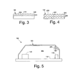
- the textured surface 200 also may include a uniform or a precision pattern 220 as is shown in exaggerated form in Fig. 4 . Any type of textured surface 200 may be used herein. Holographic patterns also may be used herein. Further, combinations of random patterns, precision patterns, holographic patterns, and the like may be used together herein.
- the injection mold may provide the textured surface 200 as part of the mold.
- the mold thus produces a textured component 230 with the textured surface 200.
- the surface properties largely may be controlled by the nature of the mold.
- the textured component 230 then may be coated or plated with a reflective coat 240 to produce the reflective diffuser 190.
- the reflective coating 240 may be metallic and the like. Many other manufacturing techniques may be used herein. For example, existing components may be textured via sandpaper and the like and then coated.
- the textured surface 200 of the reflective diffuser 190 is generally incorporated on a reflective surface 170 in the signal path where the majority of the infrared energy must pass.
- the detector reflective surface 180 is shown in Fig. 2 adjacent to the infrared detector 120.
- Fig. 5 shows a source reflective surface 250 positioned above the infrared source 110.
- Multiple reflective surfaces 170 also may be used herein.
- the printed circuit board 130 also may act as a reflective surface 170.
- the printed circuit board 130 may have a printed circuit board reflective surface 260.
- the printed circuit board reflective surface 260 may be electroplated with, for example, an electroless nickel immersion gold ("ENIG") surface 270.
- ENIG surface 270 may be sufficiently textured so as to act as a reflective diffuser 190.
- Other types of surfaces 270 may be used.
- Other components and other configurations may be used herein.
- the NDIR gas sensor 100 with the reflective diffuser 190 induces scattering into the infrared signal pulses produced by the infrared source 110. Because the reflective energy is being diffused, the signals being reflected off of the textured surface 200 of the reflective diffuser 190 may have more of an average and homogeneous signal intensity distribution.
- the reflective diffuser 190 thus reduces overall mechanical sensitivity in the waveguide 50, the infrared source 110, and the infrared detector 120 such that the NDIR gas sensor 100 as a whole may have increased stability.
- the nature of the textured surface 200 of the reflective diffuser 190 may be optimized for different gases and intended uses.
- the NDIR gas sensor 100 described herein uses the textured surface 200 of the reflective diffuser 190 as a lambertian surface to induce scattering into the signal. This scattering thus optically averages the signal.
- the signal reflected off the reflective diffuser 190 has more of an average and homogeneous signal intensity distribution because the reflective energy therein is diffused. The more homogeneous signal intensity distribution thus results in reduced sensitivity to mechanical changes and therefore an increase in overall stability.
- the NDIR gas sensor 100 herein purposefully induces such scattering for increased stability. Such an increase in stability may permit tighter accuracy specifications with lower costs.
- Other components and other configurations may be used herein.
- the NDIR gas sensor 100 also may include multiple infrared detectors 120.
- a first infrared detector 280 and a second infrared detector 290 may be used. Any number of infrared detectors 120 may be used herein.
- the infrared detectors 280, 290 may be in physically separated different locations.
- the signal reflected by the reflective diffuser 190 may result in similar energy presented to the detectors 280, 290.
- the reflective diffuser 190 thus averages the signals to allow both detectors 280, 290 to see similar intensity energy such that the sensor 100 may be less sensitive to mechanical changes.
Landscapes
- Physics & Mathematics (AREA)
- Spectroscopy & Molecular Physics (AREA)
- Health & Medical Sciences (AREA)
- Life Sciences & Earth Sciences (AREA)
- Chemical & Material Sciences (AREA)
- Analytical Chemistry (AREA)
- Biochemistry (AREA)
- General Health & Medical Sciences (AREA)
- General Physics & Mathematics (AREA)
- Immunology (AREA)
- Pathology (AREA)
- Investigating Or Analysing Materials By Optical Means (AREA)
Abstract
Description
- The present disclosure relates generally to a non-dispersive infrared gas sensor and more particularly relates to a non-dispersive infrared gas sensor with a reflective diffuser therein to promote scattering so as to reduce overall mechanical sensitivity.
- Gas sensors such as a non-dispersive infrared ("NDIR") gas sensor may measure gas concentrations based upon infrared absorption. Specifically, NDIR gas sensors measure the gas concentrations based on unique absorption characteristics specific to each gas at certain wavelengths. In other words, different gases have clearly defined absorption characteristics. The NDIR gas sensors may include an infrared source and an infrared detector. The infrared source may be modulated and the measured signal may be correlated to the gas concentrations. A waveguide may be used as the gas sample chamber between the source and the detector. The internal surface of the waveguide typically is smooth and reflective so as to minimize the scattering of the infrared light therein. The waveguide surface thus may provide near specular reflections so as to maximize the signal received at the detector.
- Although the smooth surface providing nearly specular reflections may minimize scattering and maximize the signal, a gas sensor using such a surface also may be sensitive to mechanical changes. For example, temperature changes may have an impact on the components and, hence, the reliability of the signal. As a result, known attempts to increase overall gas sensor stability have involved the use of precision components and/or bum in periods so as to stabilize the electronics therein. These techniques, however, generally may be expensive and/or time consuming.
- There is thus a desire for an improved gas sensor such as a NDIR gas sensor. Such an improved NDIR gas sensor may provide overall mechanical stability for a more homogeneous signal without requiring the use of expensive components or modifications.
- The present application and the resultant patent thus provide a non-dispersive infrared gas sensor. The non-dispersive infrared gas sensor may include an infrared source, an infrared detector, and a waveguide extending about the infrared source and the infrared detector. The waveguide may include a reflective diffuser thereon.
- The present application and the resultant patent further provide a method of measuring a concentration of a gas in a chamber. The method may include the steps of pulsing an infrared signal into the chamber, scattering the infrared signal off of a reflective diffuser, receiving the scattered infrared signal at an infrared detector, and determining the intensity of the scattered infrared signal.
- The present application and the resultant patent further provide a non-dispersive infrared gas sensor. The non-dispersive infrared gas sensor may include an infrared source, an infrared detector, and a waveguide extending about the infrared source and the infrared detector. The waveguide may include a reflective diffuser with a textured surface and a reflective coating thereon.
- These and other features and improvements of the present application and the resultant patent will become apparent to one of ordinary skill in the art upon review of the following detailed description when taken in conjunction with the several drawings and the appended claims.
-
Fig. 1 is a schematic diagram of an NDIR gas sensor. -
Fig. 2 is a schematic diagram of an NDIR gas sensor as may be described herein. -
Fig. 3 is a side cross-sectional view of a reflective diffuser as may be used with the NDIR sensor ofFig. 2 . -
Fig. 4 is an alternative embodiment of a reflective diffuser as may be used with the NDIR sensor ofFig. 2 . -
Fig. 5 is an alternative embodiment of an NDIR sensor. -
Fig. 6 is an alternative embodiment of an NDIR sensor. -
Fig. 7 is an alternative embodiment of an NDIR sensor. - Referring now to the drawings, in which like numerals refer to like elements throughout the several views,
Fig. 1 shows a typical NDIR gas sensor. Generally described, theNDIR gas sensor 10 may include aninfrared source 15 and aninfrared detector 20. More than oneinfrared detector 20 may be used. Theinfrared source 15 and theinfrared detector 20 may be positioned on a printedcircuit board 25. Theinfrared source 15 and theinfrared detector 20 may be in communication via amicroprocessor 30. Various types of amplifiers, filters, and other components also may be used. - The NDIR
sensor 10 may be enclosed by awaveguide 35. Thewaveguide 35 may define achamber 40 extending from and enclosing in part theinfrared source 15 to theinfrared detector 20. Thewaveguide 35 may include one or more internal reflective surfaces 45. The reflective surfaces 45 typically may be smooth and may provide near specular reflection so as to minimize scattering of the light therein. Thewaveguide 35 may be made from thermoplastic, metal, rubber, composite materials, and the like. If thewaveguide 35 is made out of thermoplastics, for example, the injection mold for thewaveguide 35 may be highly polished about the reflective surfaces 45. The reflective surfaces 45 then may receive a plate or coating 50. The plate orcoating 50 may be a metal surface so as to produce a near specular reflective surface 55. Specifically, such a near specular reflective surface 55 may maximize the signal received at theinfrared detector 20 by limiting scattering. - As described above, the infrared source 115 may pulse an infrared beam within the
chamber 40. The beam may reflect off of the reflective surfaces 45 of thewaveguide 35 and may be received by theinfrared detector 20. The gas within thechamber 40 absorbs radiation of a known wavelength and this absorption is a measure of the concentration of the gas. Different gases have clearly defined absorption characteristics. Theinfrared detector 20 thus delivers a signal proportional to the gas concentration to themicroprocessor 30. These signals then may be averaged. Other components and other configurations may be used. -
Fig. 2 shows aNDIR gas sensor 100 as may be described herein. Similar to that described above, theNDIR gas sensor 100 may include aninfrared source 110 and aninfrared detector 120. More than oneinfrared detector 120 may be used herein. Theinfrared source 110 and theinfrared detector 120 may be of conventional design. Theinfrared source 110 and theinfrared detector 120 may be positioned about a printedcircuit board 130 or other type of mechanical support and/or electronic connection. Theinfrared source 110 and theinfrared detector 120 may be in communication via amicroprocessor 140. Themicroprocessor 140 may be any type of programmable logic device. Various types of filters, amplifiers, and the like also may be used herein. Other components and other configurations may be used herein. - The NDIR
gas sensor 100 also may include awaveguide 150. Thewaveguide 150 may define achamber 160 therein extending from theinfrared source 110 to theinfrared detector 120. Thewaveguide 150 may be made from thermoplastics, metal, rubber, composite materials and the like. Thewaveguide 150 may have any size, shape, or configuration. - The
waveguide 150 may have one or more internalreflective surfaces 170 therein. In this example, a detectorreflective surface 180 may be positioned above theinfrared detector 120. Thereflective surface 170 may be in the form of areflective diffuser 190 instead of the specular reflective surface 55 described above. As opposed to such a smooth surface, thereflective diffuser 190 may include a non-specular or atextured surface 200. As is shown in exaggerated form inFig. 3 , thetextured surface 200 may include arandom pattern 210. Further, thetextured surface 200 also may include a uniform or aprecision pattern 220 as is shown in exaggerated form inFig. 4 . Any type oftextured surface 200 may be used herein. Holographic patterns also may be used herein. Further, combinations of random patterns, precision patterns, holographic patterns, and the like may be used together herein. - If the
waveguide 150 is injection molded thermoplastic component and the like, the injection mold may provide thetextured surface 200 as part of the mold. The mold thus produces atextured component 230 with thetextured surface 200. The surface properties largely may be controlled by the nature of the mold. Thetextured component 230 then may be coated or plated with areflective coat 240 to produce thereflective diffuser 190. Thereflective coating 240 may be metallic and the like. Many other manufacturing techniques may be used herein. For example, existing components may be textured via sandpaper and the like and then coated. - The
textured surface 200 of thereflective diffuser 190 is generally incorporated on areflective surface 170 in the signal path where the majority of the infrared energy must pass. As such, the detectorreflective surface 180 is shown inFig. 2 adjacent to theinfrared detector 120. Alternatively,Fig. 5 shows a sourcereflective surface 250 positioned above theinfrared source 110. Multiplereflective surfaces 170 also may be used herein. Moreover, the printedcircuit board 130 also may act as areflective surface 170. InFig. 6 , the printedcircuit board 130 may have a printed circuit boardreflective surface 260. The printed circuit boardreflective surface 260 may be electroplated with, for example, an electroless nickel immersion gold ("ENIG")surface 270. Such anENIG surface 270 may be sufficiently textured so as to act as areflective diffuser 190. Other types ofsurfaces 270 may be used. Other components and other configurations may be used herein. - In use, the
NDIR gas sensor 100 with thereflective diffuser 190 induces scattering into the infrared signal pulses produced by theinfrared source 110. Because the reflective energy is being diffused, the signals being reflected off of thetextured surface 200 of thereflective diffuser 190 may have more of an average and homogeneous signal intensity distribution. Thereflective diffuser 190 thus reduces overall mechanical sensitivity in thewaveguide 50, theinfrared source 110, and theinfrared detector 120 such that theNDIR gas sensor 100 as a whole may have increased stability. The nature of thetextured surface 200 of thereflective diffuser 190 may be optimized for different gases and intended uses. - Specifically, the
NDIR gas sensor 100 described herein uses thetextured surface 200 of thereflective diffuser 190 as a lambertian surface to induce scattering into the signal. This scattering thus optically averages the signal. The signal reflected off thereflective diffuser 190 has more of an average and homogeneous signal intensity distribution because the reflective energy therein is diffused. The more homogeneous signal intensity distribution thus results in reduced sensitivity to mechanical changes and therefore an increase in overall stability. As opposed to sensors with the specular surface 55 intended to reduce scattering described above, theNDIR gas sensor 100 herein purposefully induces such scattering for increased stability. Such an increase in stability may permit tighter accuracy specifications with lower costs. Other components and other configurations may be used herein. - The
NDIR gas sensor 100 also may include multipleinfrared detectors 120. In the example ofFig. 7 , a firstinfrared detector 280 and a secondinfrared detector 290 may be used. Any number ofinfrared detectors 120 may be used herein. Theinfrared detectors reflective diffuser 190 may result in similar energy presented to thedetectors reflective diffuser 190 thus averages the signals to allow bothdetectors sensor 100 may be less sensitive to mechanical changes. - It should be apparent that the foregoing relates only to certain embodiments of the present application and the resultant patent. Numerous changes and modifications may be made herein by one of ordinary skill in the art without departing from the general spirit and scope of the invention as defined by the following claims and the equivalents thereof.
- Various aspects and embodiments of the present invention are defined by the following numbered clauses:
- 1. A non-dispersive infrared gas sensor, comprising:
- an infrared source;
- an infrared detector; and
- a waveguide extending about the infrared source and the infrared detector;
- the waveguide comprising a reflective diffuser thereon.
- 2. The non-dispersive infrared gas sensor of clause 1, wherein the waveguide defines a chamber.
- 3. The non-dispersive infrared gas sensor of any preceding clause, wherein the reflective diffuser comprises a textured surface.
- 4. The non-dispersive infrared gas sensor of any preceding clause, wherein the textured surface comprises a random pattern.
- 5. The non-dispersive infrared gas sensor of any preceding clause, wherein the textured surface comprises a precision pattern.
- 6. The non-dispersive infrared gas sensor of any preceding clause, wherein the reflective diffuser comprises a reflective coating thereon.
- 7. The non-dispersive infrared gas sensor of any preceding clause, wherein the waveguide comprises a textured thermoplastic component with a reflective metallic coating thereon.
- 8. The non-dispersive infrared gas sensor of any preceding clause, wherein the reflective diffuser comprises a detector reflective surface.
- 9. The non-dispersive infrared gas sensor of any preceding clause, wherein the reflective diffuser comprises a source reflective surface.
- 10. The non-dispersive infrared gas sensor of any preceding clause, wherein the reflective diffuser comprises a printed circuit board reflective surface.
- 11. The non-dispersive infrared gas sensor of any preceding clause, wherein the printed circuit board reflective surface comprises an electroless nickel immersion gold surface.
- 12. The non-dispersive infrared gas sensor of any preceding clause, further comprising a plurality of infrared detectors.
- 13. The non-dispersive infrared gas sensor of any preceding clause, further comprising a plurality of infrared detectors spaced apart from each other.
- 14. The non-dispersive infrared gas sensor of any preceding clause, further comprising a microprocessor in communication with the infrared source and the infrared detector.
- 15. A method of measuring a concentration of a gas in a chamber, comprising:
- pulsing an infrared signal into the chamber;
- scattering the infrared signal off of a reflective diffuser;
- receiving the scattered infrared signal at an infrared detector; and
- determining the intensity of the scattered infrared signal.
- 16. A non-dispersive infrared gas sensor, comprising:
- an infrared source;
- an infrared detector; and
- a waveguide extending about the infrared source and the infrared detector;
- the waveguide comprising a reflective diffuser with a textured surface and a reflective coating thereon.
- 17. The non-dispersive infrared gas sensor of any preceding clause, wherein the textured surface comprises a random pattern or a precision pattern.
- 18. The non-dispersive infrared gas sensor of any preceding clause, wherein the reflective diffuser comprises a detector reflective surface.
- 19. The non-dispersive infrared gas sensor of any preceding clause, wherein the reflective diffuser comprises a source reflective surface.
- 20. The non-dispersive infrared gas sensor of any preceding clause, wherein the reflective diffuser comprises a printed circuit board reflective surface with an electroless nickel immersion gold surface.
Claims (15)
- A non-dispersive infrared gas sensor (100), comprising:an infrared source (110);an infrared detector (120); anda waveguide (150) extending about the infrared source and the infrared detector;the waveguide comprising a reflective diffuser (190) thereon.
- The non-dispersive infrared gas sensor (100) of claim 1, wherein the waveguide defines a chamber (160).
- The non-dispersive infrared gas sensor (100) of claim 1 or claim 2, wherein the reflective diffuser comprises a textured surface (200).
- The non-dispersive infrared gas sensor (100) of claim 3, wherein the textured surface comprises a random pattern (210), or a precision pattern (220).
- The non-dispersive infrared gas sensor (100) of claim 3, wherein the reflective diffuser comprises a reflective coating (240) thereon.
- The non-dispersive infrared gas sensor (100) of any preceding claim, wherein the waveguide comprises a textured thermoplastic component (230) with a reflective metallic coating (240) thereon.
- The non-dispersive infrared gas sensor (100) of any preceding claim, wherein the reflective diffuser comprises a detector reflective surface (180), or a source reflective surface (250).
- The non-dispersive infrared gas sensor (100) of any preceding claim, wherein the reflective diffuser comprises a printed circuit board reflective surface (260).
- The non-dispersive infrared gas sensor (100) of claim 8, wherein the printed circuit board reflective surface comprises an electroless nickel immersion gold surface (270).
- The non-dispersive infrared gas sensor (100) of any preceding claim, further comprising a plurality of infrared detectors (120), wherein, preferably, the plurality of infrared detectors spaced apart from each other.
- The non-dispersive infrared gas sensor (100) of any preceding claim, further comprising a microprocessor (140) in communication with the infrared source and the infrared detector.
- A method of measuring a concentration of a gas in a chamber (160), comprising:pulsing an infrared signal into the chamber;scattering the infrared signal off of a reflective diffuser (190);receiving the scattered infrared signal at an infrared detector (120); anddetermining the intensity of the scattered infrared signal.
- The non-dispersive infrared gas sensor of claim 1, comprising:an infrared source (110);an infrared detector (120); anda waveguide (150) extending about the infrared source and the infrared detector;the waveguide comprising a reflective diffuser (190) with a textured surface and a reflective coating thereon.
- The non-dispersive infrared gas sensor of claim 13, wherein the textured surface comprises a random pattern or a precision pattern.
- The non-dispersive infrared gas sensor of claim 13 or claim 14, wherein the reflective diffuser comprises a printed circuit board reflective surface with an electroless nickel immersion gold surface.
Applications Claiming Priority (1)
| Application Number | Priority Date | Filing Date | Title |
|---|---|---|---|
| US13/526,589 US8969808B2 (en) | 2012-06-19 | 2012-06-19 | Non-dispersive infrared sensor with a reflective diffuser |
Publications (2)
| Publication Number | Publication Date |
|---|---|
| EP2677300A2 true EP2677300A2 (en) | 2013-12-25 |
| EP2677300A3 EP2677300A3 (en) | 2014-01-29 |
Family
ID=48747315
Family Applications (1)
| Application Number | Title | Priority Date | Filing Date |
|---|---|---|---|
| EP13172490.8A Withdrawn EP2677300A3 (en) | 2012-06-19 | 2013-06-18 | Non-dispersive infrared gas sensor with a reflective diffuser |
Country Status (7)
| Country | Link |
|---|---|
| US (1) | US8969808B2 (en) |
| EP (1) | EP2677300A3 (en) |
| JP (1) | JP2014002146A (en) |
| KR (1) | KR20130142940A (en) |
| CN (1) | CN103512857A (en) |
| CA (1) | CA2818156A1 (en) |
| FI (1) | FI20135628A7 (en) |
Cited By (1)
| Publication number | Priority date | Publication date | Assignee | Title |
|---|---|---|---|---|
| WO2018024840A1 (en) * | 2016-08-05 | 2018-02-08 | Osram Opto Semiconductors Gmbh | Detection assembly and method for producing detection assemblies |
Families Citing this family (13)
| Publication number | Priority date | Publication date | Assignee | Title |
|---|---|---|---|---|
| CN104122224A (en) * | 2014-08-13 | 2014-10-29 | 成都君凌科创科技有限公司 | High-precision non-dispersion infrared ray gas sensor |
| USD764540S1 (en) * | 2014-09-26 | 2016-08-23 | Lexmark International, Inc. | Portion of a display screen with icon |
| EP3265766B1 (en) | 2015-03-05 | 2023-09-27 | Honeywell International Inc. | Use of selected glass types and glass thicknesses in the optical path to remove cross sensitivity to water absorption peaks |
| CN105006477B (en) * | 2015-08-04 | 2017-12-05 | 中国电子科技集团公司第十三研究所 | A kind of embedded refrigeration mode infrared focal plane detector connector of ceramics |
| FR3048084A1 (en) * | 2016-02-18 | 2017-08-25 | Commissariat Energie Atomique | NON-DISPERSIVE INFRARED SENSOR FOR DETECTING GAS. |
| DE102016003285A1 (en) * | 2016-03-18 | 2017-09-21 | Dräger Safety AG & Co. KGaA | In situ gas detection system for gas reactors with critical environments |
| CN105962524B (en) * | 2016-06-27 | 2017-09-29 | 尚妙根 | One kind massage intelligent protection footwear |
| US10222274B2 (en) * | 2016-09-28 | 2019-03-05 | General Electric Company | Thermographic temperature sensor |
| US10161859B2 (en) | 2016-10-27 | 2018-12-25 | Honeywell International Inc. | Planar reflective ring |
| EP3144663B1 (en) * | 2016-11-18 | 2020-06-17 | Sensirion AG | Gas sensor module |
| US20190312186A1 (en) * | 2018-04-09 | 2019-10-10 | Microsoft Technology Licensing, Llc | Side-Emitting LED with Increased Illumination |
| WO2020079960A1 (en) | 2018-10-19 | 2020-04-23 | ソニー株式会社 | Imaging device and solid-state imaging device |
| CN110371920B (en) * | 2019-07-12 | 2023-09-08 | 北京机械设备研究所 | Method and device for inhibiting vibration sensitivity of NDIR gas sensor |
Family Cites Families (10)
| Publication number | Priority date | Publication date | Assignee | Title |
|---|---|---|---|---|
| US5341214A (en) | 1989-09-06 | 1994-08-23 | Gaztech International Corporation | NDIR gas analysis using spectral ratioing technique |
| US5747808A (en) | 1994-02-14 | 1998-05-05 | Engelhard Sensor Technologies | NDIR gas sensor |
| DE19608604C2 (en) | 1996-03-06 | 1998-09-10 | Conducta Endress & Hauser | Gas analyzer and measuring cell for use in a gas analyzer |
| US6410918B1 (en) * | 1997-10-28 | 2002-06-25 | Edwards Systems Technology, Inc. | Diffusion-type NDIR gas analyzer with improved response time due to convection flow |
| US6469303B1 (en) * | 2000-05-17 | 2002-10-22 | Rae Systems, Inc. | Non-dispersive infrared gas sensor |
| GB0030675D0 (en) | 2000-12-15 | 2001-01-31 | Rue De Int Ltd | Methods of creating high efficiency diffuse back-reflectors based on embossed surface relief |
| GB0327931D0 (en) | 2003-12-02 | 2004-01-07 | City Tech | Gas sensor |
| DE102004044145B3 (en) | 2004-09-13 | 2006-04-13 | Robert Bosch Gmbh | Reflector module for a photometric gas sensor |
| DE102005032722B3 (en) | 2005-07-13 | 2006-10-05 | Tyco Electronics Raychem Gmbh | Measuring presence and/or concentration of analyte using gas sensor, by comparing first recorded value with threshold and triggering alarm if threshold is exceeded |
| EP2169384B1 (en) | 2008-09-30 | 2013-04-10 | General Electric Company | IR gas sensor with simplified beam splitter. |
-
2012
- 2012-06-19 US US13/526,589 patent/US8969808B2/en active Active
-
2013
- 2013-06-06 CA CA2818156A patent/CA2818156A1/en not_active Abandoned
- 2013-06-06 FI FI20135628A patent/FI20135628A7/en not_active Application Discontinuation
- 2013-06-14 JP JP2013125112A patent/JP2014002146A/en active Pending
- 2013-06-18 EP EP13172490.8A patent/EP2677300A3/en not_active Withdrawn
- 2013-06-18 KR KR1020130069685A patent/KR20130142940A/en not_active Withdrawn
- 2013-06-19 CN CN201310242739.9A patent/CN103512857A/en active Pending
Non-Patent Citations (1)
| Title |
|---|
| None |
Cited By (2)
| Publication number | Priority date | Publication date | Assignee | Title |
|---|---|---|---|---|
| WO2018024840A1 (en) * | 2016-08-05 | 2018-02-08 | Osram Opto Semiconductors Gmbh | Detection assembly and method for producing detection assemblies |
| US11486819B2 (en) | 2016-08-05 | 2022-11-01 | Osram Oled Gmbh | Detection arrangement and method for producing detection arrangements |
Also Published As
| Publication number | Publication date |
|---|---|
| US8969808B2 (en) | 2015-03-03 |
| EP2677300A3 (en) | 2014-01-29 |
| CA2818156A1 (en) | 2013-12-19 |
| US20130334423A1 (en) | 2013-12-19 |
| KR20130142940A (en) | 2013-12-30 |
| CN103512857A (en) | 2014-01-15 |
| JP2014002146A (en) | 2014-01-09 |
| FI20135628L (en) | 2013-12-20 |
| FI20135628A7 (en) | 2013-12-20 |
Similar Documents
| Publication | Publication Date | Title |
|---|---|---|
| US8969808B2 (en) | Non-dispersive infrared sensor with a reflective diffuser | |
| US4278353A (en) | Optical inspection of gold surfaces | |
| US20160313244A1 (en) | Optical sensing apparatus provided with light source and light detector | |
| US9536368B2 (en) | Authentication device | |
| CN102762974A (en) | Device and method for calibrating a scattered light meter | |
| CN101865840A (en) | Surface plasmon resonance imaging sensing system | |
| CN103620384A (en) | Diffuse measurement window for near and mid-IR multi-channel sensors | |
| JP2008076126A (en) | Photometric device and method | |
| CN111936049A (en) | Measurement system for spectroscopic biopsy | |
| US20200400544A1 (en) | Integrated filter-based particulate matter sensors | |
| CN102959382A (en) | Non-destructive measuring device for fruits and vegetables | |
| CN110892237A (en) | Optical sensor package and method of making the same | |
| WO2013137145A1 (en) | Non-destructive measuring device | |
| CN105223151B (en) | Optics cavity for gas detection apparatus | |
| US11921031B2 (en) | Compact gas sensor | |
| KR102246452B1 (en) | Non-dispersive Infra Red(NDIR) gas sensor and manufacturing method thereof | |
| HK1192615A (en) | Non-dispersive infrared sensor with a reflective diffuser | |
| CN118159829A (en) | Multi-wavelength ozone concentration sensor and use method | |
| US8698103B2 (en) | Measuring device for determination of at least one parameter of a blood sample | |
| CN202204759U (en) | Reaction vessel chain and biochemical analyzer with same | |
| JP2011153929A (en) | Total light quantity measurement system, total light quantity measurement apparatus, and total light quantity measurement method | |
| CN221781681U (en) | Light energy detection device | |
| TW200736593A (en) | Apparatus for measuring reflectance, method for measuring reflectance and method for manufacturing display panel | |
| CN105021289B (en) | Non-contact temperature measuring device | |
| CN118089930A (en) | Light energy detection device |
Legal Events
| Date | Code | Title | Description |
|---|---|---|---|
| PUAI | Public reference made under article 153(3) epc to a published international application that has entered the european phase |
Free format text: ORIGINAL CODE: 0009012 |
|
| AK | Designated contracting states |
Kind code of ref document: A2 Designated state(s): AL AT BE BG CH CY CZ DE DK EE ES FI FR GB GR HR HU IE IS IT LI LT LU LV MC MK MT NL NO PL PT RO RS SE SI SK SM TR |
|
| AX | Request for extension of the european patent |
Extension state: BA ME |
|
| PUAL | Search report despatched |
Free format text: ORIGINAL CODE: 0009013 |
|
| AK | Designated contracting states |
Kind code of ref document: A3 Designated state(s): AL AT BE BG CH CY CZ DE DK EE ES FI FR GB GR HR HU IE IS IT LI LT LU LV MC MK MT NL NO PL PT RO RS SE SI SK SM TR |
|
| AX | Request for extension of the european patent |
Extension state: BA ME |
|
| RIC1 | Information provided on ipc code assigned before grant |
Ipc: G01N 21/61 20060101ALI20131220BHEP Ipc: G02B 5/02 20060101ALI20131220BHEP Ipc: G01N 21/35 20060101AFI20131220BHEP |
|
| 17P | Request for examination filed |
Effective date: 20140729 |
|
| RBV | Designated contracting states (corrected) |
Designated state(s): AL AT BE BG CH CY CZ DE DK EE ES FI FR GB GR HR HU IE IS IT LI LT LU LV MC MK MT NL NO PL PT RO RS SE SI SK SM TR |
|
| RAP1 | Party data changed (applicant data changed or rights of an application transferred) |
Owner name: AMPHENOL THERMOMETRICS, INC. |
|
| 17Q | First examination report despatched |
Effective date: 20160217 |
|
| STAA | Information on the status of an ep patent application or granted ep patent |
Free format text: STATUS: THE APPLICATION IS DEEMED TO BE WITHDRAWN |
|
| 18D | Application deemed to be withdrawn |
Effective date: 20160628 |