EP2677263A1 - Wärmeübertrager - Google Patents
Wärmeübertrager Download PDFInfo
- Publication number
- EP2677263A1 EP2677263A1 EP20130170660 EP13170660A EP2677263A1 EP 2677263 A1 EP2677263 A1 EP 2677263A1 EP 20130170660 EP20130170660 EP 20130170660 EP 13170660 A EP13170660 A EP 13170660A EP 2677263 A1 EP2677263 A1 EP 2677263A1
- Authority
- EP
- European Patent Office
- Prior art keywords
- legs
- heat exchanger
- exchanger according
- tubes
- openings
- Prior art date
- Legal status (The legal status is an assumption and is not a legal conclusion. Google has not performed a legal analysis and makes no representation as to the accuracy of the status listed.)
- Granted
Links
Images


Classifications
-
- H—ELECTRICITY
- H01—ELECTRIC ELEMENTS
- H01M—PROCESSES OR MEANS, e.g. BATTERIES, FOR THE DIRECT CONVERSION OF CHEMICAL ENERGY INTO ELECTRICAL ENERGY
- H01M10/00—Secondary cells; Manufacture thereof
- H01M10/60—Heating or cooling; Temperature control
- H01M10/61—Types of temperature control
- H01M10/613—Cooling or keeping cold
-
- F—MECHANICAL ENGINEERING; LIGHTING; HEATING; WEAPONS; BLASTING
- F28—HEAT EXCHANGE IN GENERAL
- F28D—HEAT-EXCHANGE APPARATUS, NOT PROVIDED FOR IN ANOTHER SUBCLASS, IN WHICH THE HEAT-EXCHANGE MEDIA DO NOT COME INTO DIRECT CONTACT
- F28D1/00—Heat-exchange apparatus having stationary conduit assemblies for one heat-exchange medium only, the media being in contact with different sides of the conduit wall, in which the other heat-exchange medium is a large body of fluid, e.g. domestic or motor car radiators
- F28D1/02—Heat-exchange apparatus having stationary conduit assemblies for one heat-exchange medium only, the media being in contact with different sides of the conduit wall, in which the other heat-exchange medium is a large body of fluid, e.g. domestic or motor car radiators with heat-exchange conduits immersed in the body of fluid
- F28D1/04—Heat-exchange apparatus having stationary conduit assemblies for one heat-exchange medium only, the media being in contact with different sides of the conduit wall, in which the other heat-exchange medium is a large body of fluid, e.g. domestic or motor car radiators with heat-exchange conduits immersed in the body of fluid with tubular conduits
- F28D1/053—Heat-exchange apparatus having stationary conduit assemblies for one heat-exchange medium only, the media being in contact with different sides of the conduit wall, in which the other heat-exchange medium is a large body of fluid, e.g. domestic or motor car radiators with heat-exchange conduits immersed in the body of fluid with tubular conduits the conduits being straight
- F28D1/0535—Heat-exchange apparatus having stationary conduit assemblies for one heat-exchange medium only, the media being in contact with different sides of the conduit wall, in which the other heat-exchange medium is a large body of fluid, e.g. domestic or motor car radiators with heat-exchange conduits immersed in the body of fluid with tubular conduits the conduits being straight the conduits having a non-circular cross-section
- F28D1/05366—Assemblies of conduits connected to common headers, e.g. core type radiators
-
- F—MECHANICAL ENGINEERING; LIGHTING; HEATING; WEAPONS; BLASTING
- F28—HEAT EXCHANGE IN GENERAL
- F28F—DETAILS OF HEAT-EXCHANGE AND HEAT-TRANSFER APPARATUS, OF GENERAL APPLICATION
- F28F9/00—Casings; Header boxes; Auxiliary supports for elements; Auxiliary members within casings
- F28F9/02—Header boxes; End plates
- F28F9/0219—Arrangements for sealing end plates into casing or header box; Header box sub-elements
- F28F9/0224—Header boxes formed by sealing end plates into covers
-
- F—MECHANICAL ENGINEERING; LIGHTING; HEATING; WEAPONS; BLASTING
- F28—HEAT EXCHANGE IN GENERAL
- F28F—DETAILS OF HEAT-EXCHANGE AND HEAT-TRANSFER APPARATUS, OF GENERAL APPLICATION
- F28F9/00—Casings; Header boxes; Auxiliary supports for elements; Auxiliary members within casings
- F28F9/02—Header boxes; End plates
- F28F9/04—Arrangements for sealing elements into header boxes or end plates
- F28F9/16—Arrangements for sealing elements into header boxes or end plates by permanent joints, e.g. by rolling
- F28F9/18—Arrangements for sealing elements into header boxes or end plates by permanent joints, e.g. by rolling by welding
-
- H—ELECTRICITY
- H01—ELECTRIC ELEMENTS
- H01M—PROCESSES OR MEANS, e.g. BATTERIES, FOR THE DIRECT CONVERSION OF CHEMICAL ENERGY INTO ELECTRICAL ENERGY
- H01M10/00—Secondary cells; Manufacture thereof
- H01M10/60—Heating or cooling; Temperature control
- H01M10/65—Means for temperature control structurally associated with the cells
- H01M10/655—Solid structures for heat exchange or heat conduction
- H01M10/6556—Solid parts with flow channel passages or pipes for heat exchange
-
- H—ELECTRICITY
- H01—ELECTRIC ELEMENTS
- H01M—PROCESSES OR MEANS, e.g. BATTERIES, FOR THE DIRECT CONVERSION OF CHEMICAL ENERGY INTO ELECTRICAL ENERGY
- H01M8/00—Fuel cells; Manufacture thereof
- H01M8/04—Auxiliary arrangements, e.g. for control of pressure or for circulation of fluids
- H01M8/04007—Auxiliary arrangements, e.g. for control of pressure or for circulation of fluids related to heat exchange
- H01M8/04067—Heat exchange or temperature measuring elements, thermal insulation, e.g. heat pipes, heat pumps, fins
- H01M8/04074—Heat exchange unit structures specially adapted for fuel cell
-
- Y—GENERAL TAGGING OF NEW TECHNOLOGICAL DEVELOPMENTS; GENERAL TAGGING OF CROSS-SECTIONAL TECHNOLOGIES SPANNING OVER SEVERAL SECTIONS OF THE IPC; TECHNICAL SUBJECTS COVERED BY FORMER USPC CROSS-REFERENCE ART COLLECTIONS [XRACs] AND DIGESTS
- Y02—TECHNOLOGIES OR APPLICATIONS FOR MITIGATION OR ADAPTATION AGAINST CLIMATE CHANGE
- Y02E—REDUCTION OF GREENHOUSE GAS [GHG] EMISSIONS, RELATED TO ENERGY GENERATION, TRANSMISSION OR DISTRIBUTION
- Y02E60/00—Enabling technologies; Technologies with a potential or indirect contribution to GHG emissions mitigation
- Y02E60/10—Energy storage using batteries
-
- Y—GENERAL TAGGING OF NEW TECHNOLOGICAL DEVELOPMENTS; GENERAL TAGGING OF CROSS-SECTIONAL TECHNOLOGIES SPANNING OVER SEVERAL SECTIONS OF THE IPC; TECHNICAL SUBJECTS COVERED BY FORMER USPC CROSS-REFERENCE ART COLLECTIONS [XRACs] AND DIGESTS
- Y02—TECHNOLOGIES OR APPLICATIONS FOR MITIGATION OR ADAPTATION AGAINST CLIMATE CHANGE
- Y02E—REDUCTION OF GREENHOUSE GAS [GHG] EMISSIONS, RELATED TO ENERGY GENERATION, TRANSMISSION OR DISTRIBUTION
- Y02E60/00—Enabling technologies; Technologies with a potential or indirect contribution to GHG emissions mitigation
- Y02E60/30—Hydrogen technology
- Y02E60/50—Fuel cells
Definitions
- the invention relates to a heat exchanger, in particular a cooler for batteries or electronic components, in particular for motor vehicles.
- Li-ion batteries have a temperature dependence, insofar as the battery cells age much faster from a design-related temperature limit, thereby significantly reducing the life of the battery, which is unacceptable at today's prices for such batteries.
- An embodiment of the invention provides a heat exchanger, in particular for temperature control for batteries or electronics, with at least one manifold with a bottom and a lid, provided in the bottom openings for receiving pipe ends of pipes in fluid communication with the headers, wherein the Are formed manifolds of a U-shaped element with two parallel legs and a leg connecting the bottom region, wherein the openings in the floor area are provided and is provided as a lid inserted between the legs wall portion.
- the pipes are sealed at their two opposite ends in openings of headers. If only one manifold is used, it may for example be a deflection in the pipe or the pipe as a whole be deflected or bent.
- the height of the openings perpendicular to the plane of the legs substantially corresponds to the distance of the legs on its inner side. As a result, a particularly flat design is achieved. If flat tubes are used, and these are arranged with their flat side parallel to the legs, a particularly flat design is realized.
- the legs have a Lotplatt ist, which is applied to the surface of the inside of the legs.
- the tube end preferably soldered to the flat sides, at least one tube or all tubes with the two opposite legs of the soil.
- the cover is formed by a solid metal part which is preferably rectangular in section.
- the tubes are formed as flat tubes with flat sides, wherein the extension of the tubes in a plane parallel to the plane of the legs of the bottom is greater than in a plane perpendicular thereto, in particular 3 to 12 times larger is.
- a plurality of flat tubes are arranged side by side and on the flat sides of the flat tubes a plate is placed and connected to the flat tubes.
- the extent of the plate in a direction perpendicular to the plane of the legs substantially corresponds to the extension of the legs in this direction.
- the floor has passages on the outside in the floor area.
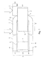
- FIG. 1 schematically shows a manifold 1 of a heat exchanger, wherein the manifold 1 consists of a bottom 2 and a lid 3.
- the manifold 1 has in the bottom 2 openings 4, inserted into the pipe ends 5 of tubes 6 and sealed are connected.
- the tubes 6 are in fluid communication with the headers 2.
- a plate 7 is still placed as a cover plate.
- the bottom 2 of the collection tube 1 is U-shaped, wherein the bottom 2 has a core material 8, which is provided with a Lotplattmaschine 9, wherein the Lotplatt ist is applied to the inside of the U-shaped bottom 2.
- the lid 3 is at the open end portion 10 of the bottom 2 between the two defining the bottom 2 together with the bottom portion 13 opposite legs 11, 12 added.
- the two legs 11, 12 are connected by a connecting bottom portion 13.
- the distance between the two legs 11, 12 essentially corresponds to the extent C2 of the tube 6 or C1 of the cover 3 in this direction.
- the thickness of the wall thickness of the collecting tube 3 is made up of a thickness of the core material 8 and plus the thickness B1 of the Lotplatt ist.
- the total height of the manifold 1 perpendicular to the plane of the legs 11, 12, in the FIG. 1 denoted as D, the sum of twice A1 plus C1 or plus C2.
- the tube 6 is inserted into the opening 4 and is thereby inserted by a path with the amount E in the manifold.
- the amount E is longer than the wall thickness A1 of the manifold, so that the tube 6 along the inner wall of the legs 11, 12 has an extension, so that the tube 6 is soldered in its area 5 with the legs 11, 12.
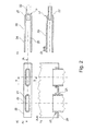
- FIG. 2a shows a section of a manifold 20 with openings 21 into which a tube 22 is inserted.
- FIG. 2b shows a section of the manifold according to the line AA FIG. 2a , It can be seen that the manifold 20 has at the edge of the openings 21 passages 23 which abut the short surfaces of the headers to achieve a better soldering.
- the Figure 2c shows the manifold of the FIG. 2a on average. It can be seen that the manifold 20 essentially consists of two legs 24, 25 and a connecting region 26 is formed, wherein the openings 21 are provided in the connecting region 26, through which the tube 22 is inserted into the collecting tube 20.
- the Figure 2d shows a section through the manifold 20 along the line BB of FIG. 2a. It can be seen that the manifold 20 has at its front end portion 27 outwardly deformed passages which are in lateral abutment with the end portion of the tube 22. This achieves improved soldering.
- FIG. 3 shows a further embodiment of a manifold 30 in the openings 31 in the bottom portion 32 of the tube sheet 33 are introduced.
- a flat tube 34 is inserted into such an opening 31.
- inwardly directed passages 36 are present, which are formed substantially in the lateral rounding area on the narrow sides of the openings 31.
- Passages 38 are provided along the longitudinal sides 37 of the openings 31, which are set to the outside, wherein these passages 38 are formed such that they have two parts, a first part 39 and a second part 40, wherein a recess 41, the two parts of Passage separates.
- the indentation serves to accommodate bulges of a cover plate.
- the collecting tube can also be provided with a bulge, in which case the cover plate would advantageously have indentations in order to receive the bulges.
- the openings 31 provided on the outside are provided on both the upper and the lower side of the openings 38.
- a notch or recess 42 is provided for the positive connection of the lid to the bottom or a lateral closure for closing off the collecting tube in the lateral direction.
- the FIG. 4 shows a section of a manifold 50 in an enlarged view.
- the manifold 50 has an opening 51 in the bottom portion 52 of the floor, the opening having rounded side short end portions 53 which are formed as inwardly directed passages.
- Side means in this context as arranged on the narrow side.
- opposite passages 54 are formed, which are directed to the outside.
- the passages 54 again have indentations or indentations 55, which are provided both centrally and in the end regions of the passages 54.
- the passages also have chamfers 56, which serve as insertion bevels for the introduction of the flat tubes into the opening 51.
- the insertion bevels are arranged on the opposite inner sides of the passages 54.
- the indentations 55 are used to position the plate or cover plate, which are placed on the flat tubes.
- FIG. 5 shows a manifold 60 with inserted into openings flat tubes 61 which are spaced from each other.
- the flat tubes come into contact with the inwardly directed passages in the region of the openings, see reference numeral 53 of FIG. 4 and with the outward passages 62. Furthermore, the constrictions 63 of the passages 62 can be seen.
- FIG. 6 shows a section of a heat exchanger in the arrangement of FIG. 5
- the cover plate 64 at its the collecting tube 60 adjacent edge projections 65 which engage in the indentations 63 of the collecting tube.
Landscapes
- Engineering & Computer Science (AREA)
- Physics & Mathematics (AREA)
- General Engineering & Computer Science (AREA)
- Mechanical Engineering (AREA)
- Thermal Sciences (AREA)
- Chemical Kinetics & Catalysis (AREA)
- General Chemical & Material Sciences (AREA)
- Electrochemistry (AREA)
- Chemical & Material Sciences (AREA)
- Manufacturing & Machinery (AREA)
- Life Sciences & Earth Sciences (AREA)
- Sustainable Development (AREA)
- Sustainable Energy (AREA)
- Heat-Exchange Devices With Radiators And Conduit Assemblies (AREA)
- Details Of Heat-Exchange And Heat-Transfer (AREA)
Abstract
Description
- Die Erfindung betrifft einen Wärmeübertrager, insbesondere einen Kühler für Batterien oder Elektronikbauteile, insbesondere für Kraftfahrzeuge.
- In Kraftfahrzeugen aber auch in anderen Anwendungen werden Batterien immer häufiger verwendet. Beim Betrieb der Batterien wird dabei Abwärme erzeugt aufgrund der Verlustwärme aufgrund der Prozesse innerhalb der Batterie selbst. Dies führt zwangsläufig zu einer Erwärmung der Batterie.
- Die dabei derzeit favorisierten Li-Ionen-Batterien weisen eine Temperaturabhängigkeit auf, insofern ab einer auch bauartbedingten Temperaturgrenze die Batteriezellen deutlich schneller altern, so dass dadurch die Lebensdauer der Batterie deutlich absinkt, was bei den heutigen Preisen für solche Batterien nicht akzeptabel ist.
- Daher ist es für solche Batterien entscheidend, die Verlustwärme der Batterie abzuführen, um keine überhöhten Temperaturen der Batterie zulassen zu müssen.
- Weiterhin haben diese Batterien bei tiefen Temperaturen den Nachteil, dass ihre Leistungsfähigkeit ebenso beschränkt ist. In solchen Situationen wäre eine Erwärmung der Batterie auf eine erhöhte Temperatur erwünscht.
- Dazu werden heute Wärmeübertrager eingesetzt, wie sie beispielsweise durch die ältere Anmeldung der Anmelderin
DE 10 2011 005 236 bekannt geworden sind. Solche Wärmeübertrager weisen jedoch hinsichtlich ihrer Ausdehnung noch Nachteile auf, weil sie relativ hoch bauen und damit mehr Bauraum erfordern als dafür in manchen Anwendungen zur Verfügung gestellt werden soll. - Es ist die Aufgabe der Erfindung, einen Wärmeübertrager der eingangs genannten Art zu schaffen, der eine geringe Bauhöhe aufweist und dennoch einfach und kostengünstig herstellbar ist.
- Dies wird mit den Merkmalen von Anspruch 1 erreicht.
- Ein Ausführungsbeispiel der Erfindung sieht einen Wärmeübertrager vor, insbesondere zur Temperierung für Batterien oder Elektronik, mit zumindest einem Sammelrohr mit einem Boden und einem Deckel, mit in dem Boden vorgesehenen Öffnungen zur Aufnahme von Rohrenden von Rohren die in Fluidkommunikation mit den Sammelrohren stehen, wobei die Sammelrohre aus einem U-förmigen Element mit zwei parallelen Schenkeln und einem die Schenkel verbindenden Bodenbereich gebildet sind, wobei die Öffnungen in dem Bodenbereich vorgesehen sind und als Deckel ein zwischen die Schenkel eingeführter Wandbereich vorgesehen ist. Dadurch kann eine flache Bauweise realisiert werden und dennoch kann eine effiziente Gestaltung mit geringem kühlmittel- bzw. kältemittelseitigem Druckabfall im Sammelrohr geschaffen werden. Vorteilhaft sind die Rohre an ihren beiden gegenüberliegenden Enden in Öffnungen von Sammelrohren abgedichtet aufgenommen. Wird nur ein Sammelrohr verwendet, so kann beispielsweise eine Umlenkung im Rohr vorliegen oder das Rohr als Ganzes umgelenkt oder umgebogen sein.
- Vorteilhaft ist insbesondere, wenn die Höhe der Öffnungen senkrecht zur Ebene der Schenkel im Wesentlichen dem Abstand der Schenkel auf ihrer Innenseite entspricht. Dadurch wird eine besonders flache Gestaltung erreicht. Wenn Flachrohre eingesetzt werden, und diese mit ihrer Flachseite parallel zu den Schenkeln angeordnet sind, wird eine besonders flache Bauweise realisiert.
- Vorteilhaft ist es, wenn die Schenkel eine Lotplattierung aufweisen, die auf der Oberfläche der Innenseite der Schenkel aufgebracht ist.
- Dadurch wird erreicht, dass die Verlötung der Außenfläche der Flachseiten der Flachrohre bzw. der Seiten der Rohre, die den Schenkeln direkt gegenüber liegen mit den Schenkeln verlötet werden. Dies erhöht die Stabilität des Sammelrohrs und kann dadurch zu einer Materialdickenreduktion im Bereich der Wandstärke des Sammelrohrs führen.
- Dabei ist es auch vorteilhaft, wenn das Rohrende, bevorzugt an den Flachseiten, zumindest eines Rohrs oder aller Rohre mit den beiden sich gegenüberliegenden Schenkeln des Bodens verlötet ist.
- Vorteilhaft ist weiterhin, wenn der Deckel durch ein im Schnitt vorzugsweise rechteckiges, massives Metallteil gebildet ist.
- Auch ist es zweckmäßig, wenn die Rohre als Flachrohre mit Flachseiten gebildet sind, wobei die Ausdehnung der Rohre in einer Ebene parallel zu der Ebene der Schenkel des Bodens größer ist als in einer dazu senkrechten Ebene, insbesondere um das 3- bis 12-fache größer ist.
- Gemäß eines weiteren vorteilhaften Ausführungsbeispiels ist es zweckmäßig, wenn eine Mehrzahl von Flachrohren nebeneinander angeordnet sind und auf die Flachseiten der Flachrohre eine Platte aufgelegt und mit den Flachrohren verbunden ist.
- Vorteilhaft ist es, wenn die Ausdehnung der Platte in einer Richtung senkrecht zur Ebene der Schenkel im Wesentlichen der Ausdehnung der Schenkel in dieser Richtung entspricht.
- Auch ist es zweckmäßig, wenn der Boden auf seiner Außenseite im Bodenbereich Durchzüge aufweist.
- Dabei ist es zweckmäßig, wenn die Durchzüge die Flachseiten der Flachrohre übergreifen. Dadurch kann auf der Außenseite des Sammelrohrs eine stabile Lötverbindung zwischen dem Rohr und dem Sammelrohr erzielt werden.
- Weitere vorteilhafte Ausgestaltungen sind durch die nachfolgende Figurenbeschreibung und durch die Unteransprüche beschrieben.
- Nachstehend wird die Erfindung auf der Grundlage zumindest eines Ausführungsbeispiels anhand der Zeichnungen näher erläutert. Es zeigen:
- Fig. 1
- eine schematische Ansicht eines Sammelrohrs eines Wärmeübertragers mit einem in eine Öffnung eingeführten Rohr,
- Fig. 2
- in Teilfiguren a), b), c) und d) jeweils Teilansichten des Sammelrohrs,
- Fig. 3
- eine dreidimensionale Ansicht eines Sammelrohrs,
- Fig. 4
- eine vergrößerte Ansicht eines Teils eines Sammelrohrs,
- Fig. 5
- eine Ansicht eines Sammelrohrs mit Flachrohren, und
- Fig. 6
- eine Ansicht eines Sammelrohrs mit Flachrohren und Deckplatte.
- Die
Figur 1 zeigt schematisch ein Sammelrohr 1 eines Wärmeübertragers, wobei das Sammelrohr 1 aus einem Boden 2 und einem Deckel 3 besteht. Das Sammelrohr 1 weist im Boden 2 Öffnungen 4 auf, in die Rohrenden 5 von Rohren 6 eingesetzt und abgedichtet verbunden sind. Die Rohre 6 stehen in Fluidkommunikation mit den Sammelrohren 2. Auf die Rohre 6 ist weiterhin eine Platte 7 als Deckplatte aufgelegt. - Der Boden 2 des Sammelrohrs 1 ist u-förmig gestaltet, wobei der Boden 2 ein Kernmaterial 8 aufweist, welches mit einer Lotplattierung 9 versehen ist, wobei die Lotplattierung auf der Innenseite des U-förmigen Bodens 2 aufgebracht ist. Der Deckel 3 ist am offenen Endbereich 10 des Bodens 2 zwischen die beiden den Boden 2 zusammen mit dem Bodenbereich 13 definierenden gegenüberliegenden Schenkel 11, 12 aufgenommen. Die beiden Schenkel 11, 12 werden durch einen verbindenden Bodenbereich 13 verbunden.
- Der Abstand zwischen den beiden Schenkeln 11,12 entspricht im Wesentlichen der Ausdehnung C2 des Rohrs 6 beziehungsweise C1 des Deckels 3 in dieser Richtung.
- Die Dicke der Wandstärke des Sammelrohrs 3 setzt sich dabei zusammen aus einer Dicke des Kernmaterials 8 und zuzüglich der Dicke B1 der Lotplattierung.
- Die Gesamthöhe des Sammelrohrs 1 senkrecht zur Ebene der Schenkel 11, 12, in der
Figur 1 als D bezeichnet, entspricht der Summe aus zweimal A1 plus C1 beziehungsweise plus C2. - Das Rohr 6 wird in die Öffnung 4 eingeschoben und wird dabei um einen Weg mit dem Betrag E in das Sammelrohr eingeschoben. Der Betrag E ist länger als die Wandstärke A1 des Sammelrohrs, so dass das Rohr 6 auch entlang der Innenwand der Schenkel 11, 12 eine Erstreckung aufweist, so dass das Rohr 6 auch in seinem Bereich 5 mit den Schenkeln 11, 12 verlötet ist.
- Die
Figur 2a zeigt einen Ausschnitt aus einem Sammelrohr 20 mit Öffnungen 21 in die ein Rohr 22 eingeführt ist. - Die
Figur 2b zeigt einen Schnitt des Sammelrohrs gemäß der Linie A-A derFigur 2a . Es ist zu erkennen, dass das Sammelrohr 20 am Rand der Öffnungen 21 Durchzüge 23 aufweist, die an den kurzen Flächen der Sammelrohre anliegen um eine bessere Verlötung zu erreichen. - Die
Figur 2c zeigt das Sammelrohr derFigur 2a im Schnitt. Dabei ist zu erkennen, dass das Sammelrohr 20 im Wesentlichen aus zwei Schenkeln 24, 25 und einen verbindenden Bereich 26 gebildet wird, wobei die Öffnungen 21 im verbindenden Bereich 26 vorgesehen sind, durch welche das Rohr 22 in das Sammelrohr 20 eingeführt ist. - Die
Figur 2d zeigt einen Schnitt durch das Sammelrohr 20 gemäß der Linie B-B derFigur 2a. Es ist zu erkennen, dass das Sammelrohr 20 an seinem vorderen Endbereich 27 nach außen verformte Durchzüge aufweist, die in seitlicher Anlage mit dem Endbereich des Rohrs 22 sind. Dadurch wird eine verbesserte Verlötung erzielt. - Die
Figur 3 zeigt ein weiteres Ausführungsbeispiel eines Sammelrohres 30 in das Öffnungen 31 im Bodenbereich 32 des Rohrbodens 33 eingebracht sind. An der linken der Seite derFigur 3 ist zu erkennen, dass ein Flachrohr 34 in eine solche Öffnung 31 eingeführt ist. Weiterhin ist zu erkennen, dass an den Schmalseiten 35 der Öffnungen 31 nach innen gestellte Durchzüge 36 vorhanden sind, die im Wesentlichen im seitlichen Rundungsbereich an den Schmalseiten der Öffnungen 31 ausgebildet sind. - Entlang der Längsseiten 37 der Öffnungen 31 sind Durchzüge 38 vorgesehen, die nach außen gestellt sind, wobei diese Durchzüge 38 derart ausgebildet sind, dass sie zwei Teile aufweisen, einen ersten Teil 39 und einen zweiten Teil 40, wobei eine Einbuchtung 41 die beiden Teile des Durchzugs trennt. Die Einbuchtung dient der Aufnahme von Ausbuchtungen einer Deckplatte. Alternativ kann das Sammelrohr auch mit einer Ausbuchtung versehen sein, wobei dann die Deckplatte vorteilhaft Einbuchtungen aufweisen würde, um die Ausbuchtungen aufzunehmen.
- Bevorzugt sind sowohl auf der oberen als auch auf der unteren Seite der Öffnungen 31 die nach außen gestellten Durchzüge 38 vorgesehen.
- Darüber hinaus ist seitlich des Sammelrohrs 30 zu erkennen, dass eine Ausklinkung oder eine Aussparung 42 vorgesehen ist, zur formschlüssigen Verbindung des Deckels mit dem Boden oder eines seitlichen Abschlusses zum Abschließen des Sammelrohrs in lateraler Richtung.
- Die
Figur 4 zeigt ein Ausschnitt eines Sammelrohrs 50 in vergrößerter Darstellung. Das Sammelrohr 50 weist eine Öffnung 51 im Bodenbereich 52 des Bodens auf, wobei die Öffnung seitliche abgerundete kurze Endbereiche 53 aufweist die als nach innen gerichtete Durchzüge ausgebildet sind. Seitlich bedeutet in diesem Zusammenhang als an der Schmalseite angeordnet. Darüber hinaus sind auf den langen Seiten der Öffnungen gegenüberliegend Durchzüge 54 ausgebildet, die nach außen gerichtet sind. Die Durchzüge 54 weisen Wiederum Einzüge bzw. Einbuchtungen 55 auf, die sowohl mittig als auch in den Endbereichen der Durchzüge 54 vorgesehen sind. Auch weisen die Durchzüge Abschrägungen 56 auf, die als Einführschrägen für die Einführung der Flachrohre in die Öffnung 51 dienen. Die Einführschrägen sind auf den sich gegenüber liegenden lnnenseiten der Durchzüge 54 angeordnet. Die Einzüge 55 dienen der Positionierung der Platte beziehungsweise Deckplatte, die auf die Flachrohre aufgelegt werden. - Die
Figur 5 zeigt ein Sammelrohr 60 mit in Öffnungen eingeführte Flachrohre 61 die beabstandet zueinander angeordnet sind. Die Flachrohre kommen im Bereich der Öffnungen in Anlage mit dem nach innen gerichteten Durchzügen, siehe Bezugszeichen 53 derFigur 4 und mit den nach außen gerichteten Durchzügen 62. Weiterhin sind die Einschnürungen 63 der Durchzüge 62 zu erkennen. - Die
Figur 6 zeigt einen Ausschnitt eines Wärmeübertragers in der Anordnung derFigur 5 mit auf die Flachrohre 61 aufgelegter Deckplatte 64. Dabei weist die Deckplatte 64 an ihrer dem Sammelrohr 60 benachbarten Kante Vorsprünge 65 auf, die in die Einbuchtungen 63 des Sammelrohres eingreifen. Dadurch wird eine formschlüssige Verbindung mit dem Sammelrohr 60 erreicht, so dass eine exakte Positionierung zwischen dem Sammelrohr 60 und der Deckplatte 64 erreicht wird.
Claims (10)
- Wärmeübertrager, insbesondere zur Temperierung für Batterien oder Elektronik, mit zumindest einem Sammelrohr mit einem Boden und einem Deckel, mit in dem Boden vorgesehenen Öffnungen zur Aufnahme von Rohrenden von Rohren, die in Fluidkommunikation mit den Sammelrohren stehen, wobei die Sammelrohre aus einem U-förmigen Element mit zwei parallelen Schenkeln und einem die Schenkel verbindenden Bodenbereich gebildet sind, wobei die Öffnungen in dem Bodenbereich vorgesehen sind und als Deckel ein zwischen die Schenkel eingeführter Wandbereich vorgesehen ist.
- Wärmeübertrager nach Anspruch 1, dadurch gekennzeichnet, dass die Höhe der Öffnungen senkrecht zur Ebene der Schenkel im Wesentlichen dem Abstand der Schenkel auf ihrer Innenseite entspricht.
- Wärmeübertrager nach einem der vorhergehenden Ansprüche, dadurch gekennzeichnet, dass die Schenkel eine Lotplattierung aufweisen, die auf der Oberfläche der Innenseite der Schenkel aufgebracht ist.
- Wärmeübertrager nach einem der vorhergehenden Ansprüche, dadurch gekennzeichnet, dass das Rohrende zumindest eines Rohrs mit den beiden sich gegenüberliegenden Schenkeln des Bodens verlötet ist.
- Wärmeübertrager nach einem der vorhergehenden Ansprüche, dadurch gekennzeichnet, dass der Deckel durch ein im Schnitt vorzugsweise rechteckiges oder rundes, massives Metallteil gebildet ist.
- Wärmeübertrager nach einem der vorhergehenden Ansprüche, dadurch gekennzeichnet, dass die Rohre als Flachrohre mit Flachseiten gebildet sind, wobei die Ausdehnung der Rohre in einer Ebene parallel zu der Ebene der Schenkel des Bodens größer ist als in einer dazu senkrechten Ebene, insbesondere um das 3- bis 12-fache größer ist.
- Wärmeübertrager nach einem der vorhergehenden Ansprüche, dadurch gekennzeichnet, dass eine Mehrzahl von Flachrohren nebeneinander angeordnet sind und auf die Flachseiten der Flachrohre eine Platte aufgelegt und mit den Flachrohren verbunden ist.
- Wärmeübertrager nach Anspruch 7, dadurch gekennzeichnet, dass die Ausdehnung der Platte in einer Richtung senkrecht zur Ebene der Schenkel im Wesentlichen der Ausdehnung der Schenkel in dieser Richtung entspricht.
- Wärmeübertrager nach einem der vorhergehenden Ansprüche, dadurch gekennzeichnet, dass der Boden auf seiner Außenseite im Bodenbereich Durchzüge aufweist.
- Wärmeübertrager nach Anspruch 9, dadurch gekennzeichnet, dass die Durchzüge die Flachseiten der Flachrohre übergreifen.
Applications Claiming Priority (1)
| Application Number | Priority Date | Filing Date | Title |
|---|---|---|---|
| DE201210210339 DE102012210339A1 (de) | 2012-06-19 | 2012-06-19 | Wärmeübertrager |
Publications (2)
| Publication Number | Publication Date |
|---|---|
| EP2677263A1 true EP2677263A1 (de) | 2013-12-25 |
| EP2677263B1 EP2677263B1 (de) | 2015-12-02 |
Family
ID=48577551
Family Applications (1)
| Application Number | Title | Priority Date | Filing Date |
|---|---|---|---|
| EP13170660.8A Not-in-force EP2677263B1 (de) | 2012-06-19 | 2013-06-05 | Wärmeübertrager |
Country Status (4)
| Country | Link |
|---|---|
| US (1) | US9553345B2 (de) |
| EP (1) | EP2677263B1 (de) |
| CN (1) | CN203586915U (de) |
| DE (1) | DE102012210339A1 (de) |
Cited By (1)
| Publication number | Priority date | Publication date | Assignee | Title |
|---|---|---|---|---|
| DE102015115608A1 (de) * | 2015-09-16 | 2017-03-16 | Dr. Ing. H.C. F. Porsche Aktiengesellschaft | Kühlsystem zum Temperieren einer Kraftfahrzeugbatterie |
Families Citing this family (1)
| Publication number | Priority date | Publication date | Assignee | Title |
|---|---|---|---|---|
| DE202017103235U1 (de) * | 2017-05-30 | 2018-08-31 | Autokühler GmbH & Co KG | Wärmeaustauscher |
Citations (5)
| Publication number | Priority date | Publication date | Assignee | Title |
|---|---|---|---|---|
| CH661464A5 (en) * | 1983-11-28 | 1987-07-31 | Runtal Holding Co Sa | Method of fabricating a heating unit |
| US20060048930A1 (en) * | 2004-09-08 | 2006-03-09 | Denso Corporation | Heat exchanger |
| EP1795853A1 (de) * | 2005-12-10 | 2007-06-13 | Delphi Technologies, Inc. | Wärmetauscher und Verfahren zu deren Herstellung |
| DE102008033594A1 (de) * | 2007-07-26 | 2009-02-26 | Behr Gmbh & Co. Kg | Boden für einen Wärmetauscher |
| DE102011005236A1 (de) | 2011-03-08 | 2012-09-13 | Behr Gmbh & Co. Kg | Sammelrohr, Wärmetauscher und Verfahren zum Herstellen eines Sammelrohres |
Family Cites Families (18)
| Publication number | Priority date | Publication date | Assignee | Title |
|---|---|---|---|---|
| US2521475A (en) * | 1948-04-15 | 1950-09-05 | Arthur J Nickolas | Freezing section |
| US3245465A (en) * | 1964-12-09 | 1966-04-12 | Young Radiator Co | Heat-exchanger core-unit construction |
| FR2504667A1 (fr) * | 1981-04-23 | 1982-10-29 | Vape Sa Ets | Connexion pour alimentation en eau d'echangeurs thermiques |
| US4722387A (en) * | 1986-02-18 | 1988-02-02 | The Garrett Corporation | Heat exchanger and method of assembly |
| JPH0284250A (ja) * | 1988-07-14 | 1990-03-26 | Showa Alum Corp | ろう付用パイプの製造方法 |
| US5228512A (en) * | 1991-04-02 | 1993-07-20 | Modine Manufacturing Company | Aluminum charge air cooler and method of making the same |
| KR950009505B1 (ko) * | 1993-03-05 | 1995-08-23 | 주식회사두원공조 | 자동차의 에어콘용 열교환기의 제조방법 |
| US5570737A (en) * | 1993-10-07 | 1996-11-05 | Showa Aluminum Corporation | Heat exchanger |
| US5881456A (en) * | 1997-03-20 | 1999-03-16 | Arup Alu-Rohr Und Profil Gmbh | Header tubes for heat exchangers and the methods used for their manufacture |
| FR2805606B1 (fr) * | 2000-02-24 | 2002-07-05 | Valeo Thermique Moteur Sa | Boite collectrice a tubulure integree pour echangeur de chaleur |
| US6462949B1 (en) * | 2000-08-07 | 2002-10-08 | Thermotek, Inc. | Electronic enclosure cooling system |
| WO2002081998A1 (en) * | 2001-04-04 | 2002-10-17 | Norsk Hydro Asa | Heat exchanger manifold |
| JP2004301454A (ja) * | 2003-03-31 | 2004-10-28 | Calsonic Kansei Corp | 熱交換器用のヘッダタンク |
| JP2005274120A (ja) * | 2004-02-24 | 2005-10-06 | Showa Denko Kk | 液冷式冷却板 |
| US7461689B2 (en) * | 2004-06-01 | 2008-12-09 | Modine Manufacturing Company | Thermal cycling resistant tube to header joint for heat exchangers |
| WO2007048888A1 (fr) * | 2005-10-28 | 2007-05-03 | Valeo Systemes Thermiques | Echangeur de chaleur à tubes plats déformés par torsion |
| US8851157B2 (en) * | 2010-05-13 | 2014-10-07 | Adams Thermal Systems, Inc. | Partial reverse ferrule header for a heat exchanger |
| DE102012217870A1 (de) * | 2012-09-28 | 2014-04-17 | Behr Gmbh & Co. Kg | Wärmeübertrager |
-
2012
- 2012-06-19 DE DE201210210339 patent/DE102012210339A1/de not_active Withdrawn
-
2013
- 2013-06-05 EP EP13170660.8A patent/EP2677263B1/de not_active Not-in-force
- 2013-06-18 CN CN201320350576.1U patent/CN203586915U/zh not_active Expired - Fee Related
- 2013-06-18 US US13/920,121 patent/US9553345B2/en active Active
Patent Citations (5)
| Publication number | Priority date | Publication date | Assignee | Title |
|---|---|---|---|---|
| CH661464A5 (en) * | 1983-11-28 | 1987-07-31 | Runtal Holding Co Sa | Method of fabricating a heating unit |
| US20060048930A1 (en) * | 2004-09-08 | 2006-03-09 | Denso Corporation | Heat exchanger |
| EP1795853A1 (de) * | 2005-12-10 | 2007-06-13 | Delphi Technologies, Inc. | Wärmetauscher und Verfahren zu deren Herstellung |
| DE102008033594A1 (de) * | 2007-07-26 | 2009-02-26 | Behr Gmbh & Co. Kg | Boden für einen Wärmetauscher |
| DE102011005236A1 (de) | 2011-03-08 | 2012-09-13 | Behr Gmbh & Co. Kg | Sammelrohr, Wärmetauscher und Verfahren zum Herstellen eines Sammelrohres |
Cited By (1)
| Publication number | Priority date | Publication date | Assignee | Title |
|---|---|---|---|---|
| DE102015115608A1 (de) * | 2015-09-16 | 2017-03-16 | Dr. Ing. H.C. F. Porsche Aktiengesellschaft | Kühlsystem zum Temperieren einer Kraftfahrzeugbatterie |
Also Published As
| Publication number | Publication date |
|---|---|
| US9553345B2 (en) | 2017-01-24 |
| EP2677263B1 (de) | 2015-12-02 |
| CN203586915U (zh) | 2014-05-07 |
| DE102012210339A1 (de) | 2013-12-19 |
| US20130333869A1 (en) | 2013-12-19 |
Similar Documents
| Publication | Publication Date | Title |
|---|---|---|
| EP1654508B2 (de) | Wärmeübertrager sowie verfahren zu dessen herstellung | |
| DE60219538T2 (de) | Wärmetauscher | |
| DE10392610B4 (de) | Verbesserter Wärmeübertrager | |
| DE102006057314B4 (de) | Wärmeaustauscher | |
| DE102006038463A1 (de) | Wärmetauschereinheit und Verfahren zu ihrer Herstellung | |
| EP2567423B1 (de) | Batteriekühler | |
| DE102013207375A1 (de) | Wärmeübertrager | |
| EP0714008A2 (de) | Wärmetauscher mit einem Sammelrohr | |
| DE112007002451T5 (de) | Wärmetauschervorrichtung | |
| DE3937463C2 (de) | Wärmeaustauscher, bestehend aus wenigstens einer an dessen Seitenflächen angebrachten Seitenwand, insbesondere ein Kühler | |
| DE102010038781A1 (de) | Kombi-Wärmetauscher und Verfahren zur Herstellung eines Kombi-Wärmetauschers | |
| DE102008033594A1 (de) | Boden für einen Wärmetauscher | |
| EP3106823B1 (de) | Wärmeübertrager | |
| DE102006002932B4 (de) | Wärmetauscher und Herstellungsverfahren für Wärmetauscher | |
| EP2677263B1 (de) | Wärmeübertrager | |
| EP2832464B1 (de) | Lamellenelement und Verfahren zur Herstellung eines Lamellenelements | |
| DE102005043093A1 (de) | Wärmetauscherrohr | |
| DE202017102436U1 (de) | Wärmetauscher mit Mikrokanal-Struktur oder Flügelrohr-Struktur | |
| EP3491323B1 (de) | Wärmetauscher mit mikrokanal-struktur oder flügelrohr-struktur | |
| EP2167895B1 (de) | Wärmetauscher | |
| DE102015111398A1 (de) | Vorrichtung zur Wärmeübertragung | |
| DE102008061762A1 (de) | Sammler eines Wärmeübertragers, insbesondere für eine Klimaanlage eines Kraftfahrzeuges sowie Wärmeübertrager, insbesondere Verdampfer für eine Kraftfahrzeugklimaanlage | |
| EP2994712B1 (de) | Wärmeübertrager | |
| DE102008013018A1 (de) | Flaches Wärmetauscherrohr | |
| EP2138798B1 (de) | Sammelkasten, insbesondere eines Wärmeübertragers eines Kraftfahrzeuges, und Wärmeübertrager, insbesondere Kondensator, eines Kraftfahrzeuges |
Legal Events
| Date | Code | Title | Description |
|---|---|---|---|
| PUAI | Public reference made under article 153(3) epc to a published international application that has entered the european phase |
Free format text: ORIGINAL CODE: 0009012 |
|
| AK | Designated contracting states |
Kind code of ref document: A1 Designated state(s): AL AT BE BG CH CY CZ DE DK EE ES FI FR GB GR HR HU IE IS IT LI LT LU LV MC MK MT NL NO PL PT RO RS SE SI SK SM TR |
|
| AX | Request for extension of the european patent |
Extension state: BA ME |
|
| 17P | Request for examination filed |
Effective date: 20140625 |
|
| RBV | Designated contracting states (corrected) |
Designated state(s): AL AT BE BG CH CY CZ DE DK EE ES FI FR GB GR HR HU IE IS IT LI LT LU LV MC MK MT NL NO PL PT RO RS SE SI SK SM TR |
|
| REG | Reference to a national code |
Ref country code: DE Ref legal event code: R079 Ref document number: 502013001545 Country of ref document: DE Free format text: PREVIOUS MAIN CLASS: F28F0009020000 Ipc: H01M0010655600 |
|
| RIC1 | Information provided on ipc code assigned before grant |
Ipc: H01M 10/6556 20140101AFI20141210BHEP |
|
| RAP1 | Party data changed (applicant data changed or rights of an application transferred) |
Owner name: MAHLE BEHR GMBH & CO. KG |
|
| GRAP | Despatch of communication of intention to grant a patent |
Free format text: ORIGINAL CODE: EPIDOSNIGR1 |
|
| INTG | Intention to grant announced |
Effective date: 20150608 |
|
| GRAS | Grant fee paid |
Free format text: ORIGINAL CODE: EPIDOSNIGR3 |
|
| GRAA | (expected) grant |
Free format text: ORIGINAL CODE: 0009210 |
|
| AK | Designated contracting states |
Kind code of ref document: B1 Designated state(s): AL AT BE BG CH CY CZ DE DK EE ES FI FR GB GR HR HU IE IS IT LI LT LU LV MC MK MT NL NO PL PT RO RS SE SI SK SM TR |
|
| REG | Reference to a national code |
Ref country code: GB Ref legal event code: FG4D Free format text: NOT ENGLISH |
|
| REG | Reference to a national code |
Ref country code: AT Ref legal event code: REF Ref document number: 763985 Country of ref document: AT Kind code of ref document: T Effective date: 20151215 Ref country code: CH Ref legal event code: EP |
|
| REG | Reference to a national code |
Ref country code: IE Ref legal event code: FG4D Free format text: LANGUAGE OF EP DOCUMENT: GERMAN |
|
| REG | Reference to a national code |
Ref country code: DE Ref legal event code: R096 Ref document number: 502013001545 Country of ref document: DE |
|
| REG | Reference to a national code |
Ref country code: NL Ref legal event code: MP Effective date: 20160302 |
|
| REG | Reference to a national code |
Ref country code: LT Ref legal event code: MG4D |
|
| PG25 | Lapsed in a contracting state [announced via postgrant information from national office to epo] |
Ref country code: ES Free format text: LAPSE BECAUSE OF FAILURE TO SUBMIT A TRANSLATION OF THE DESCRIPTION OR TO PAY THE FEE WITHIN THE PRESCRIBED TIME-LIMIT Effective date: 20151202 Ref country code: LT Free format text: LAPSE BECAUSE OF FAILURE TO SUBMIT A TRANSLATION OF THE DESCRIPTION OR TO PAY THE FEE WITHIN THE PRESCRIBED TIME-LIMIT Effective date: 20151202 Ref country code: NO Free format text: LAPSE BECAUSE OF FAILURE TO SUBMIT A TRANSLATION OF THE DESCRIPTION OR TO PAY THE FEE WITHIN THE PRESCRIBED TIME-LIMIT Effective date: 20160302 |
|
| PG25 | Lapsed in a contracting state [announced via postgrant information from national office to epo] |
Ref country code: NL Free format text: LAPSE BECAUSE OF FAILURE TO SUBMIT A TRANSLATION OF THE DESCRIPTION OR TO PAY THE FEE WITHIN THE PRESCRIBED TIME-LIMIT Effective date: 20151202 Ref country code: LV Free format text: LAPSE BECAUSE OF FAILURE TO SUBMIT A TRANSLATION OF THE DESCRIPTION OR TO PAY THE FEE WITHIN THE PRESCRIBED TIME-LIMIT Effective date: 20151202 Ref country code: PL Free format text: LAPSE BECAUSE OF FAILURE TO SUBMIT A TRANSLATION OF THE DESCRIPTION OR TO PAY THE FEE WITHIN THE PRESCRIBED TIME-LIMIT Effective date: 20151202 Ref country code: RS Free format text: LAPSE BECAUSE OF FAILURE TO SUBMIT A TRANSLATION OF THE DESCRIPTION OR TO PAY THE FEE WITHIN THE PRESCRIBED TIME-LIMIT Effective date: 20151202 Ref country code: FI Free format text: LAPSE BECAUSE OF FAILURE TO SUBMIT A TRANSLATION OF THE DESCRIPTION OR TO PAY THE FEE WITHIN THE PRESCRIBED TIME-LIMIT Effective date: 20151202 Ref country code: GR Free format text: LAPSE BECAUSE OF FAILURE TO SUBMIT A TRANSLATION OF THE DESCRIPTION OR TO PAY THE FEE WITHIN THE PRESCRIBED TIME-LIMIT Effective date: 20160303 Ref country code: SE Free format text: LAPSE BECAUSE OF FAILURE TO SUBMIT A TRANSLATION OF THE DESCRIPTION OR TO PAY THE FEE WITHIN THE PRESCRIBED TIME-LIMIT Effective date: 20151202 |
|
| REG | Reference to a national code |
Ref country code: FR Ref legal event code: PLFP Year of fee payment: 4 |
|
| PG25 | Lapsed in a contracting state [announced via postgrant information from national office to epo] |
Ref country code: IS Free format text: LAPSE BECAUSE OF FAILURE TO SUBMIT A TRANSLATION OF THE DESCRIPTION OR TO PAY THE FEE WITHIN THE PRESCRIBED TIME-LIMIT Effective date: 20151202 |
|
| PG25 | Lapsed in a contracting state [announced via postgrant information from national office to epo] |
Ref country code: CZ Free format text: LAPSE BECAUSE OF FAILURE TO SUBMIT A TRANSLATION OF THE DESCRIPTION OR TO PAY THE FEE WITHIN THE PRESCRIBED TIME-LIMIT Effective date: 20151202 |
|
| PG25 | Lapsed in a contracting state [announced via postgrant information from national office to epo] |
Ref country code: IS Free format text: LAPSE BECAUSE OF FAILURE TO SUBMIT A TRANSLATION OF THE DESCRIPTION OR TO PAY THE FEE WITHIN THE PRESCRIBED TIME-LIMIT Effective date: 20160402 Ref country code: PT Free format text: LAPSE BECAUSE OF FAILURE TO SUBMIT A TRANSLATION OF THE DESCRIPTION OR TO PAY THE FEE WITHIN THE PRESCRIBED TIME-LIMIT Effective date: 20160404 Ref country code: SK Free format text: LAPSE BECAUSE OF FAILURE TO SUBMIT A TRANSLATION OF THE DESCRIPTION OR TO PAY THE FEE WITHIN THE PRESCRIBED TIME-LIMIT Effective date: 20151202 Ref country code: EE Free format text: LAPSE BECAUSE OF FAILURE TO SUBMIT A TRANSLATION OF THE DESCRIPTION OR TO PAY THE FEE WITHIN THE PRESCRIBED TIME-LIMIT Effective date: 20151202 Ref country code: RO Free format text: LAPSE BECAUSE OF FAILURE TO SUBMIT A TRANSLATION OF THE DESCRIPTION OR TO PAY THE FEE WITHIN THE PRESCRIBED TIME-LIMIT Effective date: 20151202 Ref country code: SM Free format text: LAPSE BECAUSE OF FAILURE TO SUBMIT A TRANSLATION OF THE DESCRIPTION OR TO PAY THE FEE WITHIN THE PRESCRIBED TIME-LIMIT Effective date: 20151202 |
|
| REG | Reference to a national code |
Ref country code: DE Ref legal event code: R097 Ref document number: 502013001545 Country of ref document: DE |
|
| PLBE | No opposition filed within time limit |
Free format text: ORIGINAL CODE: 0009261 |
|
| STAA | Information on the status of an ep patent application or granted ep patent |
Free format text: STATUS: NO OPPOSITION FILED WITHIN TIME LIMIT |
|
| PG25 | Lapsed in a contracting state [announced via postgrant information from national office to epo] |
Ref country code: DK Free format text: LAPSE BECAUSE OF FAILURE TO SUBMIT A TRANSLATION OF THE DESCRIPTION OR TO PAY THE FEE WITHIN THE PRESCRIBED TIME-LIMIT Effective date: 20151202 |
|
| 26N | No opposition filed |
Effective date: 20160905 |
|
| PG25 | Lapsed in a contracting state [announced via postgrant information from national office to epo] |
Ref country code: SI Free format text: LAPSE BECAUSE OF FAILURE TO SUBMIT A TRANSLATION OF THE DESCRIPTION OR TO PAY THE FEE WITHIN THE PRESCRIBED TIME-LIMIT Effective date: 20151202 |
|
| PG25 | Lapsed in a contracting state [announced via postgrant information from national office to epo] |
Ref country code: BE Free format text: LAPSE BECAUSE OF NON-PAYMENT OF DUE FEES Effective date: 20160630 |
|
| PG25 | Lapsed in a contracting state [announced via postgrant information from national office to epo] |
Ref country code: MC Free format text: LAPSE BECAUSE OF FAILURE TO SUBMIT A TRANSLATION OF THE DESCRIPTION OR TO PAY THE FEE WITHIN THE PRESCRIBED TIME-LIMIT Effective date: 20151202 |
|
| REG | Reference to a national code |
Ref country code: CH Ref legal event code: PL |
|
| REG | Reference to a national code |
Ref country code: IE Ref legal event code: MM4A |
|
| PG25 | Lapsed in a contracting state [announced via postgrant information from national office to epo] |
Ref country code: CH Free format text: LAPSE BECAUSE OF NON-PAYMENT OF DUE FEES Effective date: 20160630 Ref country code: LI Free format text: LAPSE BECAUSE OF NON-PAYMENT OF DUE FEES Effective date: 20160630 |
|
| PG25 | Lapsed in a contracting state [announced via postgrant information from national office to epo] |
Ref country code: IE Free format text: LAPSE BECAUSE OF NON-PAYMENT OF DUE FEES Effective date: 20160605 |
|
| REG | Reference to a national code |
Ref country code: FR Ref legal event code: PLFP Year of fee payment: 5 |
|
| PG25 | Lapsed in a contracting state [announced via postgrant information from national office to epo] |
Ref country code: CY Free format text: LAPSE BECAUSE OF FAILURE TO SUBMIT A TRANSLATION OF THE DESCRIPTION OR TO PAY THE FEE WITHIN THE PRESCRIBED TIME-LIMIT Effective date: 20151202 Ref country code: HU Free format text: LAPSE BECAUSE OF FAILURE TO SUBMIT A TRANSLATION OF THE DESCRIPTION OR TO PAY THE FEE WITHIN THE PRESCRIBED TIME-LIMIT; INVALID AB INITIO Effective date: 20130605 |
|
| REG | Reference to a national code |
Ref country code: FR Ref legal event code: PLFP Year of fee payment: 6 |
|
| PG25 | Lapsed in a contracting state [announced via postgrant information from national office to epo] |
Ref country code: LU Free format text: LAPSE BECAUSE OF NON-PAYMENT OF DUE FEES Effective date: 20160605 Ref country code: MK Free format text: LAPSE BECAUSE OF FAILURE TO SUBMIT A TRANSLATION OF THE DESCRIPTION OR TO PAY THE FEE WITHIN THE PRESCRIBED TIME-LIMIT Effective date: 20151202 Ref country code: TR Free format text: LAPSE BECAUSE OF FAILURE TO SUBMIT A TRANSLATION OF THE DESCRIPTION OR TO PAY THE FEE WITHIN THE PRESCRIBED TIME-LIMIT Effective date: 20151202 Ref country code: MT Free format text: LAPSE BECAUSE OF FAILURE TO SUBMIT A TRANSLATION OF THE DESCRIPTION OR TO PAY THE FEE WITHIN THE PRESCRIBED TIME-LIMIT Effective date: 20151202 Ref country code: HR Free format text: LAPSE BECAUSE OF FAILURE TO SUBMIT A TRANSLATION OF THE DESCRIPTION OR TO PAY THE FEE WITHIN THE PRESCRIBED TIME-LIMIT Effective date: 20151202 |
|
| PG25 | Lapsed in a contracting state [announced via postgrant information from national office to epo] |
Ref country code: BG Free format text: LAPSE BECAUSE OF FAILURE TO SUBMIT A TRANSLATION OF THE DESCRIPTION OR TO PAY THE FEE WITHIN THE PRESCRIBED TIME-LIMIT Effective date: 20151202 |
|
| PG25 | Lapsed in a contracting state [announced via postgrant information from national office to epo] |
Ref country code: AL Free format text: LAPSE BECAUSE OF FAILURE TO SUBMIT A TRANSLATION OF THE DESCRIPTION OR TO PAY THE FEE WITHIN THE PRESCRIBED TIME-LIMIT Effective date: 20151202 |
|
| REG | Reference to a national code |
Ref country code: AT Ref legal event code: MM01 Ref document number: 763985 Country of ref document: AT Kind code of ref document: T Effective date: 20180605 |
|
| PG25 | Lapsed in a contracting state [announced via postgrant information from national office to epo] |
Ref country code: AT Free format text: LAPSE BECAUSE OF NON-PAYMENT OF DUE FEES Effective date: 20180605 |
|
| PGFP | Annual fee paid to national office [announced via postgrant information from national office to epo] |
Ref country code: FR Payment date: 20200620 Year of fee payment: 8 |
|
| PGFP | Annual fee paid to national office [announced via postgrant information from national office to epo] |
Ref country code: GB Payment date: 20200620 Year of fee payment: 8 |
|
| PGFP | Annual fee paid to national office [announced via postgrant information from national office to epo] |
Ref country code: DE Payment date: 20200831 Year of fee payment: 8 |
|
| PGFP | Annual fee paid to national office [announced via postgrant information from national office to epo] |
Ref country code: IT Payment date: 20200630 Year of fee payment: 8 |
|
| REG | Reference to a national code |
Ref country code: DE Ref legal event code: R119 Ref document number: 502013001545 Country of ref document: DE |
|
| GBPC | Gb: european patent ceased through non-payment of renewal fee |
Effective date: 20210605 |
|
| PG25 | Lapsed in a contracting state [announced via postgrant information from national office to epo] |
Ref country code: GB Free format text: LAPSE BECAUSE OF NON-PAYMENT OF DUE FEES Effective date: 20210605 Ref country code: DE Free format text: LAPSE BECAUSE OF NON-PAYMENT OF DUE FEES Effective date: 20220101 |
|
| PG25 | Lapsed in a contracting state [announced via postgrant information from national office to epo] |
Ref country code: FR Free format text: LAPSE BECAUSE OF NON-PAYMENT OF DUE FEES Effective date: 20210630 |
|
| PG25 | Lapsed in a contracting state [announced via postgrant information from national office to epo] |
Ref country code: IT Free format text: LAPSE BECAUSE OF NON-PAYMENT OF DUE FEES Effective date: 20210605 |