EP2677205A1 - Kettenrad mit Löseschutz mit zwangsvertiefter Seite am Kettenzahnfußteil - Google Patents
Kettenrad mit Löseschutz mit zwangsvertiefter Seite am Kettenzahnfußteil Download PDFInfo
- Publication number
- EP2677205A1 EP2677205A1 EP13173197.8A EP13173197A EP2677205A1 EP 2677205 A1 EP2677205 A1 EP 2677205A1 EP 13173197 A EP13173197 A EP 13173197A EP 2677205 A1 EP2677205 A1 EP 2677205A1
- Authority
- EP
- European Patent Office
- Prior art keywords
- chain
- chainwheel
- root portion
- face
- tooth
- Prior art date
- Legal status (The legal status is an assumption and is not a legal conclusion. Google has not performed a legal analysis and makes no representation as to the accuracy of the status listed.)
- Withdrawn
Links
Images


Classifications
-
- F—MECHANICAL ENGINEERING; LIGHTING; HEATING; WEAPONS; BLASTING
- F16—ENGINEERING ELEMENTS AND UNITS; GENERAL MEASURES FOR PRODUCING AND MAINTAINING EFFECTIVE FUNCTIONING OF MACHINES OR INSTALLATIONS; THERMAL INSULATION IN GENERAL
- F16H—GEARING
- F16H55/00—Elements with teeth or friction surfaces for conveying motion; Worms, pulleys or sheaves for gearing mechanisms
- F16H55/02—Toothed members; Worms
- F16H55/30—Chain-wheels
-
- F—MECHANICAL ENGINEERING; LIGHTING; HEATING; WEAPONS; BLASTING
- F16—ENGINEERING ELEMENTS AND UNITS; GENERAL MEASURES FOR PRODUCING AND MAINTAINING EFFECTIVE FUNCTIONING OF MACHINES OR INSTALLATIONS; THERMAL INSULATION IN GENERAL
- F16H—GEARING
- F16H35/00—Gearings or mechanisms with other special functional features
- F16H2035/001—Gearings with eccentrically mounted gears, e.g. for cyclically varying ratio
-
- F—MECHANICAL ENGINEERING; LIGHTING; HEATING; WEAPONS; BLASTING
- F16—ENGINEERING ELEMENTS AND UNITS; GENERAL MEASURES FOR PRODUCING AND MAINTAINING EFFECTIVE FUNCTIONING OF MACHINES OR INSTALLATIONS; THERMAL INSULATION IN GENERAL
- F16H—GEARING
- F16H35/00—Gearings or mechanisms with other special functional features
- F16H2035/003—Gearings comprising pulleys or toothed members of non-circular shape, e.g. elliptical gears
Definitions
- the present invention provides a novel anti-detachment chainwheel having forced recessed face at chain tooth root portion, in which a chain roller (110) sleeved on a chain connecting pivot shaft (109) can be tightened engaged at a forced recessed face at chain tooth root portion (104) while the chainwheel being driven by a chain, thereby improving the shortage of the chain being easily detached from the chainwheel;
- the anti-detachment chainwheel having forced recessed face at chain tooth root portion provided by the present invention includes unidirectional transmission and bidirectional transmission structures.
- a conventional chainwheel is often utilized for bidirectional forced transmission, and gear teeth are formed in a symmetrical structure; for smoothly guiding the chain into the chainwheel, a symmetrical chevron angled tooth face (103) having a tooth peak (105) at outer side and a wider chain tooth root portion at inner side has to be formed between the tooth shape and the chain roller (110) sleeved on a chain connecting pivot shaft (109) installed between lateral connecting sheets at each segment of the chain; however, one major shortage thereof is that when the chainwheel is driven by the chain, the oblique face formed on the chain tooth has a constant tendency of forcing the chainwheel to be outwardly detached, especially when less quantity of chain tooth being engaged with the chain, or when the chain being driven to swing towards the centrifugal direction under the situation of high speed transmission and altering load, the chain is even more likely to be detached.
- the present invention provides a novel anti-detachment chainwheel having forced recessed face at chain tooth root portion, in which a chain roller (110) sleeved on a chain connecting pivot shaft (109) can be tightened engaged at a forced recessed face at chain tooth root portion (104) while the chainwheel being driven by a chain, thereby improving the shortage of the chain being easily detached from the chainwheel.
- a chainwheel comprises a plurality of teeth, each tooth extending from a tooth root portion to a tooth peak (105) and having a pair of angled tooth faces (103); wherein at least one of the tooth faces (103) of each tooth has a recess (104) at the tooth root portion of the same side for receiving a chain roller.
- the recess (104) in each chain tooth root portion increases the steepness of the tooth face (103) and can even form an undercut.
- a conventional chainwheel is often utilized for bidirectional forced transmission, and gear teeth are formed in a symmetrical structure; for smoothly guiding the chain into the chainwheel, a symmetrical chevron angled tooth face (103) having a tooth peak (105) at outer side and a wider chain tooth root portion at inner side has to be formed between the tooth shape and the chain roller (110) sleeved on a chain connecting pivot shaft (109) installed between lateral connecting sheets at each segment of the chain; however, one major shortage thereof is that when the chainwheel is driven by the chain, the oblique face formed on the chain tooth has a constant tendency of forcing the chainwheel to be outwardly detached, especially when less quantity of chain tooth being engaged with the chain, or when the chain being driven to swing towards the centrifugal direction under the situation of high speed transmission and altering load, the chain is even more likely to be detached;
- the present invention provides a novel anti-detachment chainwheel having forced recessed face at chain tooth root portion, in which a chain roller (110) sleeved on a chain connecting pivot shaft (109) can be tightened engaged at a forced recessed face at chain tooth root portion (104) while the chainwheel being driven by a chain, thereby improving the shortage of the chain being easily detached from the chainwheel;
- the anti-detachment chainwheel having forced recessed face at chain tooth root portion provided by the present invention includes unidirectional transmission and bidirectional transmission structures, illustrated as followings:
- a symmetrical chevron angled tooth face (103) having a tooth peak (105) at outer side and a wider chain tooth root portion at inner side has to be formed between the tooth shape and the chain roller (110) sleeved on a chain connecting pivot shaft (109) installed between lateral connecting sheets at each segment of the chain;
- the present invention provides a novel anti-detachment chainwheel having forced recessed face at chain tooth root portion;
- FIG. 4 is a schematic structural view illustrating the tooth shape of a unidirectional transmission anti-detachment chainwheel composed of a right circular gear plate and formed with a forced recessed face at chain tooth root portion (104), according to the present invention
- FIG. 4 it mainly consists of:
- FIG. 5 is a schematic structural view illustrating the tooth shape of a bidirectional transmission anti-detachment chainwheel composed of a right circular gear plate and formed with a forced recessed face at chain tooth root portion (104), according to the present invention
- FIG 5 it mainly consists of:
- FIG. 6 is a schematic structural view illustrating the tooth shape of a unidirectional transmission anti-detachment chainwheel composed of an eccentric circular gear plate and formed with a forced recessed face at chain tooth root portion (104), according to the present invention
- FIG. 6 it mainly consists of:
- FIG. 7 is a schematic structural view illustrating the tooth shape of a bidirectional transmission anti-detachment chainwheel composed of an eccentric circular gear plate and formed with a forced recessed face at chain tooth root portion (104), according to the present invention
- FIG. 7 it mainly consists of:
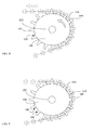
- FIG. 8 is a schematic structural view illustrating the tooth shape of a unidirectional transmission anti-detachment chainwheel composed of an oval gear plate and formed with a forced recessed face at chain tooth root portion (104), according to the present invention
- FIG. 8 it mainly consists of:
- FIG. 9 is a schematic structural view illustrating the tooth shape of a bidirectional transmission anti-detachment chainwheel composed of an oval gear plate and formed with a forced recessed face at chain tooth root portion (104), according to the present invention.
- FIG 9 it mainly consists of:
- an idle wheel having expanding or retracting force can be optionally adopted.
Landscapes
- Engineering & Computer Science (AREA)
- General Engineering & Computer Science (AREA)
- Mechanical Engineering (AREA)
- Gears, Cams (AREA)
- Devices For Conveying Motion By Means Of Endless Flexible Members (AREA)
Applications Claiming Priority (1)
| Application Number | Priority Date | Filing Date | Title |
|---|---|---|---|
| US13/529,080 US20130345005A1 (en) | 2012-06-21 | 2012-06-21 | Anti-Detachment Chainwheel having Forced Recessed Face at Chain Tooth Root Portion |
Publications (1)
| Publication Number | Publication Date |
|---|---|
| EP2677205A1 true EP2677205A1 (de) | 2013-12-25 |
Family
ID=48746240
Family Applications (1)
| Application Number | Title | Priority Date | Filing Date |
|---|---|---|---|
| EP13173197.8A Withdrawn EP2677205A1 (de) | 2012-06-21 | 2013-06-21 | Kettenrad mit Löseschutz mit zwangsvertiefter Seite am Kettenzahnfußteil |
Country Status (6)
| Country | Link |
|---|---|
| US (1) | US20130345005A1 (de) |
| EP (1) | EP2677205A1 (de) |
| JP (1) | JP2014005937A (de) |
| CN (2) | CN203363072U (de) |
| CA (1) | CA2820171A1 (de) |
| TW (2) | TW201408915A (de) |
Cited By (1)
| Publication number | Priority date | Publication date | Assignee | Title |
|---|---|---|---|---|
| WO2017034428A1 (pt) * | 2015-08-25 | 2017-03-02 | Miranda & Irmão, Lda. | Sistema de transmissão e sua utilização |
Families Citing this family (3)
| Publication number | Priority date | Publication date | Assignee | Title |
|---|---|---|---|---|
| US8992359B2 (en) * | 2012-11-09 | 2015-03-31 | Tai-Her Yang | Treadle-drive eccentric wheel transmission wheel series with periodically varied speed ratio and having inward packing auxiliary wheel |
| CN106865119B (zh) * | 2017-04-13 | 2019-01-29 | 湖南尔瞻智能科技有限公司 | 防脱落链条 |
| CN112455598B (zh) * | 2020-10-20 | 2022-04-26 | 佛山市创达力精密齿条有限公司 | 一种链条防脱落结构 |
Citations (4)
| Publication number | Priority date | Publication date | Assignee | Title |
|---|---|---|---|---|
| US3899932A (en) * | 1973-12-19 | 1975-08-19 | Roger Owen Durham | Chain retention device for elliptical sprockets |
| JPS59144855A (ja) * | 1983-02-04 | 1984-08-20 | Shimano & Co Ltd | チエンギヤ |
| EP1493946A1 (de) * | 2003-07-04 | 2005-01-05 | Tsubakimoto Chain Co. | Zahnrad für eine Kette |
| WO2008156483A1 (en) * | 2007-06-20 | 2008-12-24 | Borgwarner Inc. | Resonance tension reducing sprocket with combined radial variation and sprocket wrap |
Family Cites Families (7)
| Publication number | Priority date | Publication date | Assignee | Title |
|---|---|---|---|---|
| GB362671A (en) * | 1930-12-11 | 1931-12-10 | Mather & Platt Ltd | Improvements relating to dyeing and like machines |
| US5899477A (en) * | 1995-07-17 | 1999-05-04 | Rotor Componentes Tecnologicos S.L. | Human drive system using synchronized independent pedals with sinusoidal type variable efficiency |
| US7416500B2 (en) * | 1996-12-19 | 2008-08-26 | Cloyes Gear And Products, Inc. | Random engagement roller chain sprocket and timing chain system including same |
| US6761657B2 (en) * | 1996-12-19 | 2004-07-13 | Cloyes Gear And Products, Inc. | Roller chain sprocket with added chordal pitch reduction |
| JP3212288B2 (ja) * | 1999-03-02 | 2001-09-25 | 三協オイルレス工業株式会社 | チェーン駆動機構装置 |
| JP4357402B2 (ja) * | 2004-10-18 | 2009-11-04 | 株式会社椿本チエイン | 搬送装置 |
| JP3970281B2 (ja) * | 2004-11-19 | 2007-09-05 | 株式会社椿本チエイン | チェーン伝動装置 |
-
2012
- 2012-06-21 US US13/529,080 patent/US20130345005A1/en not_active Abandoned
-
2013
- 2013-06-19 JP JP2013128329A patent/JP2014005937A/ja active Pending
- 2013-06-20 TW TW102121837A patent/TW201408915A/zh unknown
- 2013-06-20 CA CA2820171A patent/CA2820171A1/en not_active Abandoned
- 2013-06-20 TW TW102211497U patent/TWM483342U/zh not_active IP Right Cessation
- 2013-06-21 CN CN2013203579286U patent/CN203363072U/zh not_active Expired - Fee Related
- 2013-06-21 EP EP13173197.8A patent/EP2677205A1/de not_active Withdrawn
- 2013-06-21 CN CN201310248774.1A patent/CN103511592A/zh active Pending
Patent Citations (4)
| Publication number | Priority date | Publication date | Assignee | Title |
|---|---|---|---|---|
| US3899932A (en) * | 1973-12-19 | 1975-08-19 | Roger Owen Durham | Chain retention device for elliptical sprockets |
| JPS59144855A (ja) * | 1983-02-04 | 1984-08-20 | Shimano & Co Ltd | チエンギヤ |
| EP1493946A1 (de) * | 2003-07-04 | 2005-01-05 | Tsubakimoto Chain Co. | Zahnrad für eine Kette |
| WO2008156483A1 (en) * | 2007-06-20 | 2008-12-24 | Borgwarner Inc. | Resonance tension reducing sprocket with combined radial variation and sprocket wrap |
Cited By (2)
| Publication number | Priority date | Publication date | Assignee | Title |
|---|---|---|---|---|
| WO2017034428A1 (pt) * | 2015-08-25 | 2017-03-02 | Miranda & Irmão, Lda. | Sistema de transmissão e sua utilização |
| US10780944B2 (en) | 2015-08-25 | 2020-09-22 | Miranda & Irmao, Lda. | Transmission system and its use |
Also Published As
| Publication number | Publication date |
|---|---|
| TW201408915A (zh) | 2014-03-01 |
| US20130345005A1 (en) | 2013-12-26 |
| CN103511592A (zh) | 2014-01-15 |
| CN203363072U (zh) | 2013-12-25 |
| TWM483342U (zh) | 2014-08-01 |
| CA2820171A1 (en) | 2013-12-21 |
| JP2014005937A (ja) | 2014-01-16 |
Similar Documents
| Publication | Publication Date | Title |
|---|---|---|
| EP2677205A1 (de) | Kettenrad mit Löseschutz mit zwangsvertiefter Seite am Kettenzahnfußteil | |
| EP2677204A1 (de) | Kettenrad zur Ermöglichung der positiven Rotationsübertragungs- und Rückwärtsrotationsgleitfunktionen | |
| TW201538389A (zh) | 自行車後鏈盤 | |
| JP2013515937A5 (de) | ||
| US20180363752A1 (en) | Bicycle sprocket | |
| CN104565205B (zh) | 摩托车发动机正时系统传动链条 | |
| CN204267659U (zh) | 变速箱低挡从动齿轮 | |
| CN204186936U (zh) | 防脱档的变速箱主动齿轮 | |
| CN105156619A (zh) | 复合式无级变速传动装置 | |
| CN204186933U (zh) | 防脱档的变速箱从动齿轮 | |
| US10683057B2 (en) | Guiding belt pulley for bicycle | |
| CN206487849U (zh) | 一种防脱节的机械齿轮 | |
| CN204082971U (zh) | 一种链传动离合器 | |
| CN204186952U (zh) | 双联啮合齿轮 | |
| CN204267651U (zh) | 防脱档的倒档滑动齿轮 | |
| CN207349255U (zh) | 一种后主轴 | |
| CN204459067U (zh) | 一种行星齿轮 | |
| CN203585218U (zh) | 多点啮合外齿轮减速机 | |
| CN208417462U (zh) | 一种防同步带脱落的传动轮 | |
| CN202545650U (zh) | 一种三联离合器 | |
| CN206111883U (zh) | 一种传动轴端面齿突缘叉 | |
| CN204186948U (zh) | 挂档双联从动齿轮 | |
| CN205639541U (zh) | 一种汽车用变速箱斜齿轮 | |
| CN105240473A (zh) | 一种无级变速传动装置的设计方法 | |
| CN202867765U (zh) | 起动棘轮 |
Legal Events
| Date | Code | Title | Description |
|---|---|---|---|
| PUAI | Public reference made under article 153(3) epc to a published international application that has entered the european phase |
Free format text: ORIGINAL CODE: 0009012 |
|
| AK | Designated contracting states |
Kind code of ref document: A1 Designated state(s): AL AT BE BG CH CY CZ DE DK EE ES FI FR GB GR HR HU IE IS IT LI LT LU LV MC MK MT NL NO PL PT RO RS SE SI SK SM TR |
|
| AX | Request for extension of the european patent |
Extension state: BA ME |
|
| STAA | Information on the status of an ep patent application or granted ep patent |
Free format text: STATUS: THE APPLICATION IS DEEMED TO BE WITHDRAWN |
|
| 18D | Application deemed to be withdrawn |
Effective date: 20140626 |