US10683057B2 - Guiding belt pulley for bicycle - Google Patents
Guiding belt pulley for bicycle Download PDFInfo
- Publication number
- US10683057B2 US10683057B2 US15/699,128 US201715699128A US10683057B2 US 10683057 B2 US10683057 B2 US 10683057B2 US 201715699128 A US201715699128 A US 201715699128A US 10683057 B2 US10683057 B2 US 10683057B2
- Authority
- US
- United States
- Prior art keywords
- belt
- pulley
- face
- teeth
- tooth
- Prior art date
- Legal status (The legal status is an assumption and is not a legal conclusion. Google has not performed a legal analysis and makes no representation as to the accuracy of the status listed.)
- Expired - Fee Related, expires
Links
- 230000005540 biological transmission Effects 0.000 abstract description 4
- 230000009194 climbing Effects 0.000 description 1
- 230000000295 complement effect Effects 0.000 description 1
- 238000010586 diagram Methods 0.000 description 1
Images


Classifications
-
- F—MECHANICAL ENGINEERING; LIGHTING; HEATING; WEAPONS; BLASTING
- F16—ENGINEERING ELEMENTS AND UNITS; GENERAL MEASURES FOR PRODUCING AND MAINTAINING EFFECTIVE FUNCTIONING OF MACHINES OR INSTALLATIONS; THERMAL INSULATION IN GENERAL
- F16H—GEARING
- F16H7/00—Gearings for conveying rotary motion by endless flexible members
- F16H7/02—Gearings for conveying rotary motion by endless flexible members with belts; with V-belts
- F16H7/023—Gearings for conveying rotary motion by endless flexible members with belts; with V-belts with belts having a toothed contact surface or regularly spaced bosses or hollows for slipless or nearly slipless meshing with complementary profiled contact surface of a pulley
-
- B—PERFORMING OPERATIONS; TRANSPORTING
- B62—LAND VEHICLES FOR TRAVELLING OTHERWISE THAN ON RAILS
- B62M—RIDER PROPULSION OF WHEELED VEHICLES OR SLEDGES; POWERED PROPULSION OF SLEDGES OR SINGLE-TRACK CYCLES; TRANSMISSIONS SPECIALLY ADAPTED FOR SUCH VEHICLES
- B62M9/00—Transmissions characterised by use of an endless chain, belt, or the like
- B62M9/02—Transmissions characterised by use of an endless chain, belt, or the like of unchangeable ratio
-
- F—MECHANICAL ENGINEERING; LIGHTING; HEATING; WEAPONS; BLASTING
- F16—ENGINEERING ELEMENTS AND UNITS; GENERAL MEASURES FOR PRODUCING AND MAINTAINING EFFECTIVE FUNCTIONING OF MACHINES OR INSTALLATIONS; THERMAL INSULATION IN GENERAL
- F16H—GEARING
- F16H7/00—Gearings for conveying rotary motion by endless flexible members
- F16H7/18—Means for guiding or supporting belts, ropes, or chains
- F16H2007/185—Means for guiding or supporting belts, ropes, or chains the guiding surface in contact with the belt, rope or chain having particular shapes, structures or materials
Definitions
- the present invention relates to a bicycle, and more particularly to a guiding belt pulley for a bicycle.
- a conventional driving mechanism of a bicycle includes a belt pulley 90 with teeth 92 meshed with a belt 94 with teeth 96 .
- the teeth 92 of the belt pulley 90 are complementary to a ring configuration 98 and pass through radial lines P of teeth 92 . Therefore, two of the neighboring teeth 96 of the belt 94 are attached to opposite faces of the teeth 92 when the belt pulley 90 is meshed with the belt 94 .
- a rider steps cranks to turn the belt pulley 90 so as to drive the belt.
- the belt 94 is looped over two belt pulleys with a predetermined tension to have teeth 96 of the belt 94 firmly engaged with the teeth 92 of the belt pulleys 90 .
- a tension of the belt 94 at a top of the belt pulley 90 is greater than that of the belt 94 at a bottom of the belt pulley 90 , so the belt 94 at the top of the belt pulley 90 will have a deformation greater than that at the bottom of the belt pulley 90 , and this deformation may disengage the belt 94 .
- Such disengagement will happen frequently when the bicycle is starting to go, or is climbing.
- the primary objective of the present invention is to provide a guiding belt pulley for a bicycle, which reduces a risk of disengagement of the belt when the belt is taken a large torque.
- the secondary objective of the present invention is to provide a guiding belt pulley for a bicycle, which provides a high efficiency and safe torque transmission.
- a guiding belt pulley which is configured to engage a belt with belt teeth, includes a ring configuration having a root circle at an edge thereof and a plurality of pulley teeth projected from the root circle of the ring configuration.
- Each of the pulley teeth has a first face, a second face, and a top land, wherein the first and the second faces are at opposite sides of the pulley tooth, and the top land is on a top of the pulley tooth and between the first and the second faces.
- a first curved face is formed between the first face and the top land, and a second curved face formed between the second face and the top land.
- the first face has a first root end, which connects to the root circle, and a first top end, which connecting to the top land.
- the first face has a length, which is a distance between the first root end and the first top end.
- the second face has a second root end, which connects to the root circle, and a second top end, which connecting to the top land.
- the second face has a length, which is a distance between the second root end and the second top end.
- Each of the pulley teeth slants related to a radial line of the ring configuration.
- a shaft gap and a move gap are formed between the pulley teeth and the belt teeth when they are engaged. These two gaps may provide spaces for the belt teeth to deform and shift when taking a great torque to reduce a risk of disengagement of the belt.
- FIG. 1 is a sketch diagram of the engagement of the teeth of the conventional belt pulley and the conventional belt;
- FIG. 2 is an exploded view of a preferred embodiment of the present invention
- FIG. 3 is a front view of the belt pulley of the preferred embodiment of the present invention.
- FIG. 4 is an enlarged view of the pulley teeth of the belt pulley of the preferred embodiment of the present invention.
- FIG. 5 is another enlarged view of the pulley teeth of the belt pulley of the preferred embodiment of the present invention.
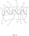
- FIG. 6 is a partial sectional view of the preferred embodiment of the present invention.
- FIG. 7 is an enlarged view of the preferred embodiment of the present invention, showing the engagement of the pulley teeth of the belt pulley and of the belt teeth of the belt;
- FIG. 8 is another enlarged view of the preferred embodiment of the present invention, showing the engagement of the pulley teeth of the belt pulley and of the belt teeth of the belt.
- FIG. 2 shows a belt 10 and a guiding belt pulley 20 of the preferred embodiment of the present invention.
- the belt 10 has a plurality of belt teeth 12 on an interior side thereof.
- the guiding belt pulley 20 has a ring configuration 22 , on an edge of which a plurality of pulley teeth 24 are projected.
- the pulley teeth 24 of the guiding belt pulley 20 engage the belt teeth 12 of the belt 10 to transmit power.
- the belt 10 and the guiding belt pulley 20 are configured to be applied in a bicycle.
- the edge of the ring configuration 22 of the guiding belt pulley 20 is defined as a root circle 220 , and the pulley teeth 24 are projected from the root circle 220 .
- each of the pulley teeth 24 of the guiding belt pulley 20 has a first face 240 , a second face 242 , and a top land 244 .
- the first and the second faces 240 , 242 are at opposite sides of the pulley tooth 24
- the top land 244 is on a top of the pulley tooth 24 and between the first and the second faces 240 , 242 .
- Each pulley tooth 24 further has a first curved face 246 between the first face 240 and the top land 244 , and a second curved face 248 between the second face 242 and the top land 244 .
- the first face 240 has a first root end 26 , which connects to the root circle 220 , and a first top end 28 , which connecting to the top land 244 .
- the first face 240 has a length 30 , which is a distance between the first root end 26 and the first top end 28 .
- the second face 242 has a second root end 32 , which connects to the root circle 220 , and a second top end 34 , which connecting to the top land 244 .
- the second face 242 has a length 36 , which is a distance between the second root end 32 and the second top end 34 .
- the length 36 of the second face 242 is longer than the length 30 of the first face 240 , and a radius of curvature of the second curved face 248 is greater than a radius of curvature of the first curved face 246 .
- a radius of curvature of the second curved face 248 is equal to a radius of curvature of the first curved face 246 .
- each of the pulley teeth 24 of the guiding belt pulley 20 has a radial line L, which passes a center of the guiding belt pulley 20 , and first face 240 and the second face 242 are asymmetric related to the radial line L. Therefore, the pulley teeth 24 slant to the second faces 242 respectively.
- a groove 38 is formed between each two of the neighboring pulley teeth 24 to receive the belt tooth 12 of the belt 10 .
- the grooves 38 are asymmetric and slanted related to the radial line L, so that a shift gap 40 is left between the belt tooth 12 and the first face 240 when the belt tooth 12 is received in the groove 38 .
- the belt teeth 12 of the belt 10 are attached to the first curved faces 246 of the pulley teeth 24 , and a move gap 42 is left between the second curved face 248 of the pulley tooth 24 and another belt tooth 12 of the belt 10 .
- the present invention provides the shift gap 40 and the move gap 42 to take a shift and a deformation of the belt tooth 12 of the belt 10 . It may reduce a risk of disengagement of the belt 10 and the guiding belt pulley 20 when a large torque is transmitted. In other words, the present invention may allow a large torque transmission, and provide a safe way of power transmission.
Landscapes
- Engineering & Computer Science (AREA)
- General Engineering & Computer Science (AREA)
- Mechanical Engineering (AREA)
- Chemical & Material Sciences (AREA)
- Combustion & Propulsion (AREA)
- Transportation (AREA)
- Pulleys (AREA)
Abstract
Description
Claims (4)
Priority Applications (1)
| Application Number | Priority Date | Filing Date | Title |
|---|---|---|---|
| US15/699,128 US10683057B2 (en) | 2017-09-08 | 2017-09-08 | Guiding belt pulley for bicycle |
Applications Claiming Priority (1)
| Application Number | Priority Date | Filing Date | Title |
|---|---|---|---|
| US15/699,128 US10683057B2 (en) | 2017-09-08 | 2017-09-08 | Guiding belt pulley for bicycle |
Publications (2)
| Publication Number | Publication Date |
|---|---|
| US20190077486A1 US20190077486A1 (en) | 2019-03-14 |
| US10683057B2 true US10683057B2 (en) | 2020-06-16 |
Family
ID=65630642
Family Applications (1)
| Application Number | Title | Priority Date | Filing Date |
|---|---|---|---|
| US15/699,128 Expired - Fee Related US10683057B2 (en) | 2017-09-08 | 2017-09-08 | Guiding belt pulley for bicycle |
Country Status (1)
| Country | Link |
|---|---|
| US (1) | US10683057B2 (en) |
Families Citing this family (1)
| Publication number | Priority date | Publication date | Assignee | Title |
|---|---|---|---|---|
| DE102024113010A1 (en) * | 2024-05-08 | 2025-11-13 | Karlheinz Nicolai | Toothed belt pulley with improved engagement, as well as belt drive, bicycle and kit |
Citations (5)
| Publication number | Priority date | Publication date | Assignee | Title |
|---|---|---|---|---|
| US1480528A (en) * | 1922-09-16 | 1924-01-08 | Morse Chain Co | Drive chain |
| US3387437A (en) * | 1967-07-26 | 1968-06-11 | Orlando N. Owen | Pneumatic cotton harvester |
| US20150152941A1 (en) * | 2012-08-09 | 2015-06-04 | Bando Chemical Industries, Ltd. | Toothed belt and belt reduction gear including the same |
| US20160339995A1 (en) * | 2015-05-20 | 2016-11-24 | Shimano Inc. | Interchangeable bicycle sprocket |
| US10309515B2 (en) * | 2017-04-17 | 2019-06-04 | Shimano Inc. | Bicycle rear sprocket |
-
2017
- 2017-09-08 US US15/699,128 patent/US10683057B2/en not_active Expired - Fee Related
Patent Citations (6)
| Publication number | Priority date | Publication date | Assignee | Title |
|---|---|---|---|---|
| US1480528A (en) * | 1922-09-16 | 1924-01-08 | Morse Chain Co | Drive chain |
| US3387437A (en) * | 1967-07-26 | 1968-06-11 | Orlando N. Owen | Pneumatic cotton harvester |
| US20150152941A1 (en) * | 2012-08-09 | 2015-06-04 | Bando Chemical Industries, Ltd. | Toothed belt and belt reduction gear including the same |
| US20160339995A1 (en) * | 2015-05-20 | 2016-11-24 | Shimano Inc. | Interchangeable bicycle sprocket |
| US10155566B2 (en) * | 2015-05-20 | 2018-12-18 | Shimano Inc. | Interchangeable bicycle sprocket |
| US10309515B2 (en) * | 2017-04-17 | 2019-06-04 | Shimano Inc. | Bicycle rear sprocket |
Also Published As
| Publication number | Publication date |
|---|---|
| US20190077486A1 (en) | 2019-03-14 |
Similar Documents
| Publication | Publication Date | Title |
|---|---|---|
| US11092217B2 (en) | Belt drive system | |
| US9541159B2 (en) | Chain plate structure | |
| US8647223B2 (en) | V-belt | |
| US20090258740A1 (en) | Toothed wheel and group of toothed wheels for a bicycle transmission system | |
| US8690719B2 (en) | Push type driving belt | |
| US20080305906A1 (en) | Transmission belt | |
| US8888374B1 (en) | Bearing with antiskid design | |
| JP6094911B2 (en) | Metal belt for continuously variable transmission | |
| EP2243980A1 (en) | Element of belt for continuously variable transmission and belt for continuously variable transmission | |
| US10683057B2 (en) | Guiding belt pulley for bicycle | |
| US20110065541A1 (en) | Sprocket assembly | |
| KR102326544B1 (en) | Harmonic reducer | |
| TW201641836A (en) | Belt and pulley with positioning structure | |
| EP2677204A1 (en) | Chainwheel enabling positive rotational transmission and reverse rotational sliding features | |
| EP2677205A1 (en) | Anti-detachment chainwheel having forced recessed face at chain tooth root portion | |
| CN101263322B (en) | Multiple ribbed pulley and system | |
| JP2007187304A (en) | Belt for continuously variable transmission, and continuously variable transmission including the same | |
| US11661998B2 (en) | Power transmission chain | |
| JP3189716B2 (en) | V-belt for continuously variable transmission | |
| JP2017180784A (en) | Transmission belt | |
| JP2006017279A (en) | Driving chain | |
| JP2018123926A (en) | Transmission belt | |
| JP2007146987A (en) | Pulley of belt type continuously variable transmission | |
| JP2011080487A (en) | Power transmission belt | |
| TW201537061A (en) | Link plate structure having two working spaces |
Legal Events
| Date | Code | Title | Description |
|---|---|---|---|
| AS | Assignment |
Owner name: DRIVETRAIN TECH SOLUTION INC., TAIWAN Free format text: ASSIGNMENT OF ASSIGNORS INTEREST;ASSIGNOR:CHEN, PO CHENG;REEL/FRAME:043532/0651 Effective date: 20170904 |
|
| FEPP | Fee payment procedure |
Free format text: ENTITY STATUS SET TO UNDISCOUNTED (ORIGINAL EVENT CODE: BIG.); ENTITY STATUS OF PATENT OWNER: SMALL ENTITY |
|
| FEPP | Fee payment procedure |
Free format text: ENTITY STATUS SET TO SMALL (ORIGINAL EVENT CODE: SMAL); ENTITY STATUS OF PATENT OWNER: SMALL ENTITY |
|
| STPP | Information on status: patent application and granting procedure in general |
Free format text: DOCKETED NEW CASE - READY FOR EXAMINATION |
|
| STPP | Information on status: patent application and granting procedure in general |
Free format text: NON FINAL ACTION MAILED |
|
| STPP | Information on status: patent application and granting procedure in general |
Free format text: RESPONSE TO NON-FINAL OFFICE ACTION ENTERED AND FORWARDED TO EXAMINER |
|
| STPP | Information on status: patent application and granting procedure in general |
Free format text: NON FINAL ACTION MAILED |
|
| STPP | Information on status: patent application and granting procedure in general |
Free format text: NOTICE OF ALLOWANCE MAILED -- APPLICATION RECEIVED IN OFFICE OF PUBLICATIONS |
|
| STPP | Information on status: patent application and granting procedure in general |
Free format text: PUBLICATIONS -- ISSUE FEE PAYMENT VERIFIED |
|
| STCF | Information on status: patent grant |
Free format text: PATENTED CASE |
|
| FEPP | Fee payment procedure |
Free format text: MAINTENANCE FEE REMINDER MAILED (ORIGINAL EVENT CODE: REM.); ENTITY STATUS OF PATENT OWNER: SMALL ENTITY |
|
| LAPS | Lapse for failure to pay maintenance fees |
Free format text: PATENT EXPIRED FOR FAILURE TO PAY MAINTENANCE FEES (ORIGINAL EVENT CODE: EXP.); ENTITY STATUS OF PATENT OWNER: SMALL ENTITY |
|
| STCH | Information on status: patent discontinuation |
Free format text: PATENT EXPIRED DUE TO NONPAYMENT OF MAINTENANCE FEES UNDER 37 CFR 1.362 |
|
| FP | Lapsed due to failure to pay maintenance fee |
Effective date: 20240616 |