EP2676849B1 - Control unit for vehicle door - Google Patents
Control unit for vehicle door Download PDFInfo
- Publication number
- EP2676849B1 EP2676849B1 EP13172285.2A EP13172285A EP2676849B1 EP 2676849 B1 EP2676849 B1 EP 2676849B1 EP 13172285 A EP13172285 A EP 13172285A EP 2676849 B1 EP2676849 B1 EP 2676849B1
- Authority
- EP
- European Patent Office
- Prior art keywords
- control unit
- lock
- door
- housing
- arm
- Prior art date
- Legal status (The legal status is an assumption and is not a legal conclusion. Google has not performed a legal analysis and makes no representation as to the accuracy of the status listed.)
- Active
Links
- 238000009434 installation Methods 0.000 claims description 3
- 238000006073 displacement reaction Methods 0.000 claims description 2
- 230000004913 activation Effects 0.000 claims 1
- 238000013461 design Methods 0.000 description 20
- 230000001276 controlling effect Effects 0.000 description 8
- 238000004519 manufacturing process Methods 0.000 description 5
- 230000008901 benefit Effects 0.000 description 3
- 230000007246 mechanism Effects 0.000 description 3
- 238000010586 diagram Methods 0.000 description 2
- 230000008859 change Effects 0.000 description 1
- 238000004891 communication Methods 0.000 description 1
- 238000010276 construction Methods 0.000 description 1
- 239000000428 dust Substances 0.000 description 1
- 230000000694 effects Effects 0.000 description 1
- 239000012535 impurity Substances 0.000 description 1
- 238000012986 modification Methods 0.000 description 1
- 230000004048 modification Effects 0.000 description 1
- 238000003825 pressing Methods 0.000 description 1
- 230000001681 protective effect Effects 0.000 description 1
- 230000001105 regulatory effect Effects 0.000 description 1
- 239000000779 smoke Substances 0.000 description 1
Images
Classifications
-
- E—FIXED CONSTRUCTIONS
- E05—LOCKS; KEYS; WINDOW OR DOOR FITTINGS; SAFES
- E05B—LOCKS; ACCESSORIES THEREFOR; HANDCUFFS
- E05B85/00—Details of vehicle locks not provided for in groups E05B77/00 - E05B83/00
- E05B85/10—Handles
- E05B85/12—Inner door handles
-
- B—PERFORMING OPERATIONS; TRANSPORTING
- B60—VEHICLES IN GENERAL
- B60N—SEATS SPECIALLY ADAPTED FOR VEHICLES; VEHICLE PASSENGER ACCOMMODATION NOT OTHERWISE PROVIDED FOR
- B60N2/00—Seats specially adapted for vehicles; Arrangement or mounting of seats in vehicles
- B60N2/75—Arm-rests
- B60N2/79—Adaptations for additional use of the arm-rests
- B60N2/797—Adaptations for additional use of the arm-rests for use as electrical control means, e.g. switches
-
- B—PERFORMING OPERATIONS; TRANSPORTING
- B60—VEHICLES IN GENERAL
- B60R—VEHICLES, VEHICLE FITTINGS, OR VEHICLE PARTS, NOT OTHERWISE PROVIDED FOR
- B60R16/00—Electric or fluid circuits specially adapted for vehicles and not otherwise provided for; Arrangement of elements of electric or fluid circuits specially adapted for vehicles and not otherwise provided for
- B60R16/02—Electric or fluid circuits specially adapted for vehicles and not otherwise provided for; Arrangement of elements of electric or fluid circuits specially adapted for vehicles and not otherwise provided for electric constitutive elements
-
- E—FIXED CONSTRUCTIONS
- E05—LOCKS; KEYS; WINDOW OR DOOR FITTINGS; SAFES
- E05B—LOCKS; ACCESSORIES THEREFOR; HANDCUFFS
- E05B77/00—Vehicle locks characterised by special functions or purposes
- E05B77/22—Functions related to actuation of locks from the passenger compartment of the vehicle
-
- E—FIXED CONSTRUCTIONS
- E05—LOCKS; KEYS; WINDOW OR DOOR FITTINGS; SAFES
- E05B—LOCKS; ACCESSORIES THEREFOR; HANDCUFFS
- E05B79/00—Mounting or connecting vehicle locks or parts thereof
- E05B79/02—Mounting of vehicle locks or parts thereof
- E05B79/04—Mounting of lock casings to the vehicle, e.g. to the wing
-
- E—FIXED CONSTRUCTIONS
- E05—LOCKS; KEYS; WINDOW OR DOOR FITTINGS; SAFES
- E05B—LOCKS; ACCESSORIES THEREFOR; HANDCUFFS
- E05B81/00—Power-actuated vehicle locks
- E05B81/54—Electrical circuits
- E05B81/64—Monitoring or sensing, e.g. by using switches or sensors
- E05B81/76—Detection of handle operation; Detection of a user approaching a handle; Electrical switching actions performed by door handles
-
- E—FIXED CONSTRUCTIONS
- E05—LOCKS; KEYS; WINDOW OR DOOR FITTINGS; SAFES
- E05B—LOCKS; ACCESSORIES THEREFOR; HANDCUFFS
- E05B83/00—Vehicle locks specially adapted for particular types of wing or vehicle
- E05B83/02—Locks for railway freight-cars, freight containers or the like; Locks for the cargo compartments of commercial lorries, trucks or vans
-
- E—FIXED CONSTRUCTIONS
- E05—LOCKS; KEYS; WINDOW OR DOOR FITTINGS; SAFES
- E05B—LOCKS; ACCESSORIES THEREFOR; HANDCUFFS
- E05B83/00—Vehicle locks specially adapted for particular types of wing or vehicle
- E05B83/36—Locks for passenger or like doors
- E05B83/42—Locks for passenger or like doors for large commercial vehicles, e.g. trucks, construction vehicles or vehicles for mass transport
-
- E—FIXED CONSTRUCTIONS
- E05—LOCKS; KEYS; WINDOW OR DOOR FITTINGS; SAFES
- E05B—LOCKS; ACCESSORIES THEREFOR; HANDCUFFS
- E05B85/00—Details of vehicle locks not provided for in groups E05B77/00 - E05B83/00
- E05B85/02—Lock casings
-
- H—ELECTRICITY
- H01—ELECTRIC ELEMENTS
- H01H—ELECTRIC SWITCHES; RELAYS; SELECTORS; EMERGENCY PROTECTIVE DEVICES
- H01H13/00—Switches having rectilinearly-movable operating part or parts adapted for pushing or pulling in one direction only, e.g. push-button switch
- H01H13/02—Details
- H01H13/04—Cases; Covers
-
- E—FIXED CONSTRUCTIONS
- E05—LOCKS; KEYS; WINDOW OR DOOR FITTINGS; SAFES
- E05B—LOCKS; ACCESSORIES THEREFOR; HANDCUFFS
- E05B79/00—Mounting or connecting vehicle locks or parts thereof
- E05B79/10—Connections between movable lock parts
- E05B79/20—Connections between movable lock parts using flexible connections, e.g. Bowden cables
-
- E—FIXED CONSTRUCTIONS
- E05—LOCKS; KEYS; WINDOW OR DOOR FITTINGS; SAFES
- E05Y—INDEXING SCHEME ASSOCIATED WITH SUBCLASSES E05D AND E05F, RELATING TO CONSTRUCTION ELEMENTS, ELECTRIC CONTROL, POWER SUPPLY, POWER SIGNAL OR TRANSMISSION, USER INTERFACES, MOUNTING OR COUPLING, DETAILS, ACCESSORIES, AUXILIARY OPERATIONS NOT OTHERWISE PROVIDED FOR, APPLICATION THEREOF
- E05Y2600/00—Mounting or coupling arrangements for elements provided for in this subclass
- E05Y2600/40—Mounting location; Visibility of the elements
- E05Y2600/45—Mounting location; Visibility of the elements in or on the fixed frame
-
- E—FIXED CONSTRUCTIONS
- E05—LOCKS; KEYS; WINDOW OR DOOR FITTINGS; SAFES
- E05Y—INDEXING SCHEME ASSOCIATED WITH SUBCLASSES E05D AND E05F, RELATING TO CONSTRUCTION ELEMENTS, ELECTRIC CONTROL, POWER SUPPLY, POWER SIGNAL OR TRANSMISSION, USER INTERFACES, MOUNTING OR COUPLING, DETAILS, ACCESSORIES, AUXILIARY OPERATIONS NOT OTHERWISE PROVIDED FOR, APPLICATION THEREOF
- E05Y2800/00—Details, accessories and auxiliary operations not otherwise provided for
- E05Y2800/15—Applicability
- E05Y2800/17—Universally applicable
- E05Y2800/176—Universally applicable on different wing types, weights or sizes
-
- E—FIXED CONSTRUCTIONS
- E05—LOCKS; KEYS; WINDOW OR DOOR FITTINGS; SAFES
- E05Y—INDEXING SCHEME ASSOCIATED WITH SUBCLASSES E05D AND E05F, RELATING TO CONSTRUCTION ELEMENTS, ELECTRIC CONTROL, POWER SUPPLY, POWER SIGNAL OR TRANSMISSION, USER INTERFACES, MOUNTING OR COUPLING, DETAILS, ACCESSORIES, AUXILIARY OPERATIONS NOT OTHERWISE PROVIDED FOR, APPLICATION THEREOF
- E05Y2900/00—Application of doors, windows, wings or fittings thereof
- E05Y2900/50—Application of doors, windows, wings or fittings thereof for vehicles
- E05Y2900/516—Application of doors, windows, wings or fittings thereof for vehicles for trucks or trailers
-
- H—ELECTRICITY
- H01—ELECTRIC ELEMENTS
- H01H—ELECTRIC SWITCHES; RELAYS; SELECTORS; EMERGENCY PROTECTIVE DEVICES
- H01H13/00—Switches having rectilinearly-movable operating part or parts adapted for pushing or pulling in one direction only, e.g. push-button switch
- H01H13/70—Switches having rectilinearly-movable operating part or parts adapted for pushing or pulling in one direction only, e.g. push-button switch having a plurality of operating members associated with different sets of contacts, e.g. keyboard
- H01H13/702—Switches having rectilinearly-movable operating part or parts adapted for pushing or pulling in one direction only, e.g. push-button switch having a plurality of operating members associated with different sets of contacts, e.g. keyboard with contacts carried by or formed from layers in a multilayer structure, e.g. membrane switches
- H01H13/705—Switches having rectilinearly-movable operating part or parts adapted for pushing or pulling in one direction only, e.g. push-button switch having a plurality of operating members associated with different sets of contacts, e.g. keyboard with contacts carried by or formed from layers in a multilayer structure, e.g. membrane switches characterised by construction, mounting or arrangement of operating parts, e.g. push-buttons or keys
- H01H13/7057—Switches having rectilinearly-movable operating part or parts adapted for pushing or pulling in one direction only, e.g. push-button switch having a plurality of operating members associated with different sets of contacts, e.g. keyboard with contacts carried by or formed from layers in a multilayer structure, e.g. membrane switches characterised by construction, mounting or arrangement of operating parts, e.g. push-buttons or keys characterised by the arrangement of operating parts in relation to each other, e.g. pre-assembled groups of keys
-
- H—ELECTRICITY
- H01—ELECTRIC ELEMENTS
- H01H—ELECTRIC SWITCHES; RELAYS; SELECTORS; EMERGENCY PROTECTIVE DEVICES
- H01H2300/00—Orthogonal indexing scheme relating to electric switches, relays, selectors or emergency protective devices covered by H01H
- H01H2300/01—Application power window
Definitions
- the present invention concerns a control unit preferably for disposal/installation on the inside of a vehicle door and arranged so that said control unit can control an electrical or mechanical door lock.
- the invention is intended primarily for heavier/commercial vehicles such as goods vehicles and the like, but can naturally also be used in other vehicles with lockable doors and a risk of break-in, such as cars, construction machinery, airplanes, aquatic vessels etc.
- the invention also concerns a vehicle equipped with a control unit according to the invention.
- Vehicles are normally equipped with lockable doors to prevent break-ins and thefts from the vehicles, and to reduce the risk of the driver being assaulted and robbed.
- a vehicle is normally equipped with a lock mechanism in the door that is controlled/regulated by either electrical or mechanical means.
- Mechanical and electrical locks can be installed in parallel during the production of vehicles, and on the same types of vehicles.
- a control or actuating unit disposed on the inside of the driver door is utilized, which unit is usually disposed in the inside panel of the door in a location that is readily accessible to the driver, so that the driver can, by means of a simple manipulation, control the impulse that sets the lock in its locked or unlocked position.
- Different control units are used at present for the different lock types.
- Electrical lock designs are normally unlocked or locked by means of an electrical button or switch, the actuation of which influences an electrical motor or solenoid in the lock.
- Mechanical lock designs are normally controlled by means of a mechanical control that transfers a motion via a drawbar or cables, thereby influencing the locking/unlocking mechanism of the lock.
- control unit for the door lock can be standardized in terms of its form and function and installed in the same location in the inside panel of the door.
- different variants of door panels do not need to be used, regardless of whether an electrical or a mechanical lock design is used in the door. This simplifies the manufacturing process and makes it more cost-effective. Further cost benefits are achieved if, in addition, largely the same components can be used in the relevant control unit for actuating and controlling both electrical and mechanical lock designs.
- Using the same control unit and disposing the actuating control for locking or unlocking the door lock in the same location in the control unit are also advantageous in that evacuating the vehicle is also simplified, e.g. in a panic situation and particularly if the visibility in the cab is limited by darkness or smoke. In such crisis or panic situations it has been found that drivers will attempt to open the door in their accustomed manner, and readily forget whether the unlocking control is disposed elsewhere on the inside of the door. It is thus desirable for the vehicle to always be able to be unlocked using the normal and accustomed actuating control.
- US20070126242 describes, for example, a design comprising a housing that can house various actuating elements for controlling the lock.
- the actuator that controls the central lock of the vehicle can, for example, be inactivated so as to prevent opening of the door lock.
- the various embodiments of the design use the same lock housing and thus the same installation space in the vehicle door.
- This invention is focused on the design of the components in the vehicle door that perform the actual locking function in the door, and not on the control unit per se.
- DE102008049118 describes an actuating lever, which is arranged in the respective vehicle door. The actuating lever is designed such that locking and unlocking of all the vehicle doors and the vehicle flaps are carried out with the actuating lever.
- control units consist in that they are not suitably flexible and easy to adapt to different door lock designs, and that they do not enable the same housing to be equipped with different actuating elements in a simple manner.
- the prior art thus provides no control unit that anticipates the present invention, or that is sufficiently flexible in an efficient, function and cost-effective manner.
- the object of the invention is to solve the foregoing problems and provide a control unit that can control the door lock in a vehicle door regardless of whether said lock is of the mechanical or electrical type.
- a further object of the invention is that the control unit be equipped with an actuating control that can easily be replaced and adapted based on whether the door lock is of the mechanical or electrical type.
- a further object of the invention is that the actuating control be disposed in the same location in the control unit, so that no new manipulation needs to be learned by the driver in order to operate the door lock mechanism, regardless of whether the door is equipped with a mechanical or an electrical door lock.
- control unit be simple and functional in terms of its design, and easy to incorporate in a vehicle without modifications to the panel components of the vehicle.
- a further object of the invention is that the control unit be easy to adapt to the relevant door lock design.
- a further object of the invention is that the components involved consist of as few parts as possible, and that they be easy and inexpensive to fabricate.
- Vehicle doors can thus be equipped with either mechanical or electrical lock designs, wherein the lock function is in both cases actuated, i.e. locked and/or unlocked, by means of an electrical impulse from the control unit disposed on the inside of the door.
- An electrical lock design is normally actuated by means of an electric switch, often a button that acts mechanically upon a circuit breaker, while a mechanical lock design is normally actuated by means of an actuating control that transfers a mechanical motion to the lock design in the vehicle door by means of drawbars or cables.
- the invention is realized primarily by arranging the actuating control so as to generate an unlocking or locking impulse to the lock design of the vehicle door in the same location in the control unit, regardless of whether a mechanical or an electrical lock is installed in the vehicle door.
- the solutions entails that the housing of the control unit is arranged with a space in which either of at least two different modules are interchangeably disposable, so that the control unit is designed and prepared for two different functions, which are achieved in that different modularly designed actuating elements can be arranged in and used in the control unit, depending upon the desired function.
- the modules consist of actuating elements/lock buttons, for example, in that an electric switch is arranged in the control unit, and partly in that recesses for a mechanical actuating control are simultaneously arranged in the same part of the control unit.
- the switch is preferably disposed on a circuit board arranged inside the control unit in such a position that it can be acted upon by a rocker button or a button that is depressable against the effect of a spring force, which button is made of plastic or the like.
- a rocker or pivotable actuating element is arranged in the same space but comprises a shaft/lever that can be coupled to an outer drawbar or cables, which are in turn in mechanical communication with the mechanical door lock.
- the circuit board/control unit suitably also comprises switches and or actuating elements/buttons for controlling other functions in the vehicle, such as window-opening devices and external rearview mirrors.
- the control unit is also equipped with a cable case top that is arranged or integrated in the plastic next to the control unit housing and equipped with grooves or recesses in the upper edge of the housing, proximate to but beneath the cover cap, which recesses function as bearing pivots for the actuating element/rocker. Because the sealed circuit board is disposed beneath all the switches in the control unit, it does not matter that the groove/recess is present, even if the control unit is to be used solely for an electrical door lock. The need for different types of cover plates in the control unit is obviated, as no cavities need to be covered.
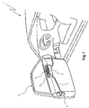
- FIG. 1 shows a block diagram, in a perspective view, of a commonly occurring vehicle 1 with a door 2 equipped with a control unit 3 for electrical control of a lock 4 arranged in the rear edge of the door 2.
- the door 2 is shown here without its inside panel for the sake of clarity.
- the control unit 3 comprises a plurality of actuating elements or buttons 5 by means of which a driver can adjust the side windows, external rearview mirrors etc of the vehicle.
- the driver can, by means of an additional actuating element, i.e. a lock button 6, control the door lock 4, i.e. send an electrical impulse that locks or unlocks the door lock 4.
- An electrical wire 7 transfers the impulse between the control unit 3 and the lock 4.
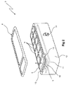
- FIG. 2 shows a control unit 3 according to the invention without obscuring surrounding door components, and with an upper cover cap 8 removed.
- the control unit 3 is, as noted above, equipped with a number of actuating elements 5,6 that are, for example, square or rectangular in shape and made of plastic, which elements mechanically influence, when physically activated by means of, for example, elements 9, a switch 10 (only one indicated by a broken line) mounted on a circuit board 11(indicated by broken lines) disposed inside the control unit housing 12 immediately below the actuating elements 5,6.
- the side walls of the housing 12 are provided at their upper edges with recesses 13, and a cable case lock 14 is arranged on one side of the housing 12, which cable case lock is either mounted on the housing 12 or integrated with the housing 12.
- the control unit 3 is, in this exemplary embodiment, equipped with an essentially flat and rectangular lock button 6 made of plastic, by means of which the electrical door lock can be controlled.
- the cover cap 8 is mostly a design detail, and its primary function is to protect the interior of the control unit 3 so that dust and impurities do not penetrate and affect or damage the function of the control unit 3.
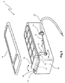
- Figure 3 shows the control unit 3 according to the invention equipped with an actuating device, e.g. in the form of a lock button 16 with a rocker function for controlling a mechanical door lock.
- the lock button 16 replaces the pushbutton 6 in Figure 2 , and is limitedly pivotable or rotatable about a shaft 17 forward or backward in the longitudinal direction of the control unit 3.
- an arm 18 that extends out through the sidewall of the housing 12.
- the arm 18 is provided with an angled portion, the angle portion, which extends downward in relation to the lock button 16 and its shaft 17 and constitutes a lever that amplifies the pivoting motion of the lock button 16, whereupon a lever is formed that describes a swinging motion when the rocker button is activated by the user.
- the swinging motion amplifies the pivoting motion of the rocker button 16.
- the pivot points of the lock button 16 are both disposed in the recesses 13 of the housing 12, and the fastening of the arm 18 functions as a pivot point.
- An additional pivot point 19 is disposed at the other short side of the lock button 16.
- a cable fastener 20 in which a cable 21 can be mounted, for example by means of a clamping or snapping arrangement.
- a mechanical pivoting motion in the rocker button 16 can, by means of this arrangement, generate an axial displacement of the cable 21, which in turn mechanically influences the mechanical lock of the driver side door (not shown).
- the cable case lock 14 is intended to make it possible to easily install, for example by securely pressing/snapping, a cable case 22, and to thereby secure same in a given position in the housing 12.
Landscapes
- Engineering & Computer Science (AREA)
- Mechanical Engineering (AREA)
- Aviation & Aerospace Engineering (AREA)
- Transportation (AREA)
- Lock And Its Accessories (AREA)
Description
- The present invention concerns a control unit preferably for disposal/installation on the inside of a vehicle door and arranged so that said control unit can control an electrical or mechanical door lock. The invention is intended primarily for heavier/commercial vehicles such as goods vehicles and the like, but can naturally also be used in other vehicles with lockable doors and a risk of break-in, such as cars, construction machinery, airplanes, aquatic vessels etc. The invention also concerns a vehicle equipped with a control unit according to the invention.
- Vehicles are normally equipped with lockable doors to prevent break-ins and thefts from the vehicles, and to reduce the risk of the driver being assaulted and robbed. A vehicle is normally equipped with a lock mechanism in the door that is controlled/regulated by either electrical or mechanical means. Mechanical and electrical locks can be installed in parallel during the production of vehicles, and on the same types of vehicles. In both cases a control or actuating unit disposed on the inside of the driver door is utilized, which unit is usually disposed in the inside panel of the door in a location that is readily accessible to the driver, so that the driver can, by means of a simple manipulation, control the impulse that sets the lock in its locked or unlocked position. Different control units are used at present for the different lock types. Electrical lock designs are normally unlocked or locked by means of an electrical button or switch, the actuation of which influences an electrical motor or solenoid in the lock. Mechanical lock designs are normally controlled by means of a mechanical control that transfers a motion via a drawbar or cables, thereby influencing the locking/unlocking mechanism of the lock.
- It is important, from the standpoint of both the comfort and safety of the user and from a production standpoint for the manufacturer, that the control unit for the door lock can be standardized in terms of its form and function and installed in the same location in the inside panel of the door. As a result, different variants of door panels do not need to be used, regardless of whether an electrical or a mechanical lock design is used in the door. This simplifies the manufacturing process and makes it more cost-effective. Further cost benefits are achieved if, in addition, largely the same components can be used in the relevant control unit for actuating and controlling both electrical and mechanical lock designs.
- Using the same control unit and disposing the actuating control for locking or unlocking the door lock in the same location in the control unit are also advantageous in that evacuating the vehicle is also simplified, e.g. in a panic situation and particularly if the visibility in the cab is limited by darkness or smoke. In such crisis or panic situations it has been found that drivers will attempt to open the door in their accustomed manner, and readily forget whether the unlocking control is disposed elsewhere on the inside of the door. It is thus desirable for the vehicle to always be able to be unlocked using the normal and accustomed actuating control.
- There are numerous known solutions and designs of control units for actuating door locks, and for their disposal on the inside of a vehicle door.
US20070126242 describes, for example, a design comprising a housing that can house various actuating elements for controlling the lock. The actuator that controls the central lock of the vehicle can, for example, be inactivated so as to prevent opening of the door lock. The various embodiments of the design use the same lock housing and thus the same installation space in the vehicle door. This invention is focused on the design of the components in the vehicle door that perform the actual locking function in the door, and not on the control unit per se.DE102008049118 describes an actuating lever, which is arranged in the respective vehicle door. The actuating lever is designed such that locking and unlocking of all the vehicle doors and the vehicle flaps are carried out with the actuating lever. - Other solutions for control units are described in, for example,
US2007/0095633 ,US6657316 ,US2006/0175185 etc, but none of them describes a modular design that makes it easy to change and adapt the control function in the control panel for an electrical or mechanical door lock. - The disadvantages of known solutions for control units consist in that they are not suitably flexible and easy to adapt to different door lock designs, and that they do not enable the same housing to be equipped with different actuating elements in a simple manner. The prior art thus provides no control unit that anticipates the present invention, or that is sufficiently flexible in an efficient, function and cost-effective manner.
- The object of the invention is to solve the foregoing problems and provide a control unit that can control the door lock in a vehicle door regardless of whether said lock is of the mechanical or electrical type.
- A further object of the invention is that the control unit be equipped with an actuating control that can easily be replaced and adapted based on whether the door lock is of the mechanical or electrical type.
- A further object of the invention is that the actuating control be disposed in the same location in the control unit, so that no new manipulation needs to be learned by the driver in order to operate the door lock mechanism, regardless of whether the door is equipped with a mechanical or an electrical door lock.
- A further object of the invention is that the control unit be simple and functional in terms of its design, and easy to incorporate in a vehicle without modifications to the panel components of the vehicle.
- A further object of the invention is that the control unit be easy to adapt to the relevant door lock design.
- A further object of the invention is that the components involved consist of as few parts as possible, and that they be easy and inexpensive to fabricate.
- These and other objects and advantages are achieved according to the invention by a device as defined by the features specified in the characterizing portion of independent claim 1.
- Vehicle doors can thus be equipped with either mechanical or electrical lock designs, wherein the lock function is in both cases actuated, i.e. locked and/or unlocked, by means of an electrical impulse from the control unit disposed on the inside of the door. An electrical lock design is normally actuated by means of an electric switch, often a button that acts mechanically upon a circuit breaker, while a mechanical lock design is normally actuated by means of an actuating control that transfers a mechanical motion to the lock design in the vehicle door by means of drawbars or cables.
- The invention is realized primarily by arranging the actuating control so as to generate an unlocking or locking impulse to the lock design of the vehicle door in the same location in the control unit, regardless of whether a mechanical or an electrical lock is installed in the vehicle door. The solutions entails that the housing of the control unit is arranged with a space in which either of at least two different modules are interchangeably disposable, so that the control unit is designed and prepared for two different functions, which are achieved in that different modularly designed actuating elements can be arranged in and used in the control unit, depending upon the desired function.
- This is achieved partly in that the modules consist of actuating elements/lock buttons, for example, in that an electric switch is arranged in the control unit, and partly in that recesses for a mechanical actuating control are simultaneously arranged in the same part of the control unit. The switch is preferably disposed on a circuit board arranged inside the control unit in such a position that it can be acted upon by a rocker button or a button that is depressable against the effect of a spring force, which button is made of plastic or the like. Alternatively a rocker or pivotable actuating element is arranged in the same space but comprises a shaft/lever that can be coupled to an outer drawbar or cables, which are in turn in mechanical communication with the mechanical door lock.
- The circuit board/control unit suitably also comprises switches and or actuating elements/buttons for controlling other functions in the vehicle, such as window-opening devices and external rearview mirrors.
- Given a modular solution according to the invention, wherein the actuating elements for controlling electrical or mechanical lock designs are disposed in the same location in the control unit, neither the components in the door that surround the control unit nor the components that are arranged in the control unit itself are notably affected. The choice is thus between installing a single button for actuating an electrical lock or a limitedly pivotable actuating element for a mechanical lock. In the first case the control unit is connected by means of an electrical cable to the lock, while in the second case the control unit is connected by means of a cable or drawbar to the mechanical door lock. The control unit and its internal components are the same, and the control unit can also be modified for the relevant lock design after the fact.
- The control unit is also equipped with a cable case top that is arranged or integrated in the plastic next to the control unit housing and equipped with grooves or recesses in the upper edge of the housing, proximate to but beneath the cover cap, which recesses function as bearing pivots for the actuating element/rocker. Because the sealed circuit board is disposed beneath all the switches in the control unit, it does not matter that the groove/recess is present, even if the control unit is to be used solely for an electrical door lock. The need for different types of cover plates in the control unit is obviated, as no cavities need to be covered.
- Nor does the solution according to the invention require any changes in the inside panel of the door, which means that it is easy and inexpensive to implement the new solution in a production line for manufacturing new vehicles. This solution according to the invention also makes it possible to upgrade control units on vehicles already produced.
- Additional features and advantages of the invention are presented in the following more detailed description of the invention, and in the accompanying drawings and other claims.
- The invention is described in greater detail below in several preferred exemplary embodiments, based on the accompanying drawings.
-
Figure 1 shows a block diagram, in a perspective view, of a commonly occurring vehicle door equipped with a control unit for controlling an electrical door lock, wherein the door is shown without its inside panel for the sake of clarity. -
Figure 2 shows a control unit according to the invention equipped with recesses for a mechanical control unit and a cable case lock arranged at the side of the control unit, but here equipped with a button for controlling an electrical door lock. -
Figure 3 shows a control unit according to the invention with a mechanical actuating element for controlling a mechanical door lock. -
Figure 1 shows a block diagram, in a perspective view, of a commonly occurring vehicle 1 with adoor 2 equipped with acontrol unit 3 for electrical control of alock 4 arranged in the rear edge of thedoor 2. Thedoor 2 is shown here without its inside panel for the sake of clarity. Thecontrol unit 3 comprises a plurality of actuating elements orbuttons 5 by means of which a driver can adjust the side windows, external rearview mirrors etc of the vehicle. The driver can, by means of an additional actuating element, i.e. alock button 6, control thedoor lock 4, i.e. send an electrical impulse that locks or unlocks thedoor lock 4. Anelectrical wire 7 transfers the impulse between thecontrol unit 3 and thelock 4. -
Figure 2 shows acontrol unit 3 according to the invention without obscuring surrounding door components, and with anupper cover cap 8 removed. Thecontrol unit 3 is, as noted above, equipped with a number ofactuating elements elements 9, a switch 10 (only one indicated by a broken line) mounted on a circuit board 11(indicated by broken lines) disposed inside thecontrol unit housing 12 immediately below theactuating elements housing 12 are provided at their upper edges withrecesses 13, and acable case lock 14 is arranged on one side of thehousing 12, which cable case lock is either mounted on thehousing 12 or integrated with thehousing 12. Thecontrol unit 3 is, in this exemplary embodiment, equipped with an essentially flat andrectangular lock button 6 made of plastic, by means of which the electrical door lock can be controlled. Thecover cap 8 is mostly a design detail, and its primary function is to protect the interior of thecontrol unit 3 so that dust and impurities do not penetrate and affect or damage the function of thecontrol unit 3. -
Figure 3 shows thecontrol unit 3 according to the invention equipped with an actuating device, e.g. in the form of alock button 16 with a rocker function for controlling a mechanical door lock. Thelock button 16 replaces thepushbutton 6 inFigure 2 , and is limitedly pivotable or rotatable about ashaft 17 forward or backward in the longitudinal direction of thecontrol unit 3. - On one short side of the
lock button 16 there is arranged anarm 18 that extends out through the sidewall of thehousing 12. Thearm 18 is provided with an angled portion, the angle portion, which extends downward in relation to thelock button 16 and itsshaft 17 and constitutes a lever that amplifies the pivoting motion of thelock button 16, whereupon a lever is formed that describes a swinging motion when the rocker button is activated by the user. The swinging motion amplifies the pivoting motion of therocker button 16. The pivot points of thelock button 16 are both disposed in therecesses 13 of thehousing 12, and the fastening of thearm 18 functions as a pivot point. Anadditional pivot point 19 is disposed at the other short side of thelock button 16. - In the lower/outer end of the arm there is arranged a
cable fastener 20 in which acable 21 can be mounted, for example by means of a clamping or snapping arrangement. A mechanical pivoting motion in therocker button 16 can, by means of this arrangement, generate an axial displacement of thecable 21, which in turn mechanically influences the mechanical lock of the driver side door (not shown). - The
cable case lock 14 is intended to make it possible to easily install, for example by securely pressing/snapping, acable case 22, and to thereby secure same in a given position in thehousing 12. - The foregoing description is intended primarily to facilitate an understanding of the invention, and naturally is not limited to the presented embodiments, but rather other variants of the invention are possible and conceivable within the framework of the concept of the invention and the protective scope of the following claims.
Claims (10)
- A control unit (3) for installation on the inside of a vehicle door and intended to control the lock function of the vehicle door lock (4) comprising a housing (12) with at least one actuating element (5,6) for electrical or mechanical control of the lock function and the housing (12) is arranged with a space in which either of at least two different modules (6,16) are interchangeably disposable
characterized in that
the modules consist of actuating elements/lock buttons (6,16), at least the one module, a lock button (16), is arranged so as to be pivotably mounted on bearings about a shaft (17) in recesses (13) in the housing (12), further the lock button (16) is equipped with an arm (18) arranged so as to extend out from the housing (12) through one of the recesses (13). - A control unit (3) according to claim 1,
characterized in that
the lock button (16) is arranged so as to generate, in connection with its physical activation/actuation, a pivoting or swinging motion about the shaft (17). - A control unit (3) according to any of claims 1-2,
characterized in that
the fastening of the arm (18) in the recess (13) constitutes a pivot point. - A control unit (3) according to any of claims 1-3,
characterized in that
an additional pivot point (19) is arranged at the opposite short side of the lock button (16). - A control unit (3) according to any of claims 1-4,
characterized in that
the arm (18) is equipped with an angle portion that extends downward in relation to the lock button (16) and its shaft (17) and constitutes a lever that amplifies the pivoting motion of the lock button (16). - A control unit (3) according to any of claims 1-5,
characterized in that
in the outermost end of the arm (18) there is arranged a fastener (20) for installing, for example, a cable (21), which transfers a mechanical motion to the door lock (4). - A control unit (3) according to claim 6,
characterized in that
the fastener (20) consists of a clamp or snap device. - A control unit (3) according to any of claims 1-7,
characterized in that
the arm (18) is arranged so as to generate an axial displacement of the cable (21), which motion can be transferred to the door lock (4). - A control unit (3) according to any of claims 6-8,
characterized in that
a cable case lock (14) is arranged on the outside of the control unit housing (12) and intended to secure the case for the cable (21). - A vehicle equipped with a control unit according to any of claims 1-9.
Applications Claiming Priority (1)
| Application Number | Priority Date | Filing Date | Title |
|---|---|---|---|
| SE1250647A SE536932C2 (en) | 2012-06-19 | 2012-06-19 | Vehicle door control unit |
Publications (3)
| Publication Number | Publication Date |
|---|---|
| EP2676849A2 EP2676849A2 (en) | 2013-12-25 |
| EP2676849A3 EP2676849A3 (en) | 2014-07-09 |
| EP2676849B1 true EP2676849B1 (en) | 2016-11-09 |
Family
ID=48703140
Family Applications (1)
| Application Number | Title | Priority Date | Filing Date |
|---|---|---|---|
| EP13172285.2A Active EP2676849B1 (en) | 2012-06-19 | 2013-06-17 | Control unit for vehicle door |
Country Status (4)
| Country | Link |
|---|---|
| EP (1) | EP2676849B1 (en) |
| CN (1) | CN103510769B (en) |
| BR (1) | BR102013014860B1 (en) |
| SE (1) | SE536932C2 (en) |
Families Citing this family (3)
| Publication number | Priority date | Publication date | Assignee | Title |
|---|---|---|---|---|
| EP3411325B1 (en) | 2016-02-05 | 2022-09-28 | Crown Equipment Corporation | Control elements for materials handling vehicles |
| CN114673409B (en) * | 2022-04-29 | 2023-09-12 | 浙江吉利控股集团有限公司 | Door inner switch and automobile |
| DE102022212807A1 (en) * | 2022-11-29 | 2024-05-29 | Volkswagen Aktiengesellschaft | Interior panel for a vehicle door with a horizontally arranged operating lever for unlocking the door lock and a corresponding operating lever with grip edge |
Family Cites Families (11)
| Publication number | Priority date | Publication date | Assignee | Title |
|---|---|---|---|---|
| CN1052285A (en) * | 1989-12-09 | 1991-06-19 | 石润基 | The switch that is used for the power-operated window for vehicle of automobile |
| US6657316B1 (en) | 1998-12-23 | 2003-12-02 | Johnson Contols Interiors Technology Corporation | Window control apparatus |
| US6445082B1 (en) * | 1999-11-04 | 2002-09-03 | Daimlerchrysler Corporation | Vehicle window switch orientation |
| US6961644B2 (en) * | 2002-12-12 | 2005-11-01 | Alps Automotive, Inc. | Dual haptic vehicle control and display system |
| DE102004002756A1 (en) | 2004-01-20 | 2005-08-11 | Daimlerchrysler Ag | Lock of a vehicle door |
| JP4286794B2 (en) | 2005-02-09 | 2009-07-01 | オムロン株式会社 | Switch device |
| DE102005041081A1 (en) * | 2005-08-30 | 2007-03-01 | D. la Porte Söhne GmbH | Actuation device for door or flap lock, has pusher staying in connection with locking device having remote-controlled electric motor, where locking device is designed as module-like and/or cartridge-like and inserted in handle body |
| JP4652957B2 (en) | 2005-10-31 | 2011-03-16 | 東洋電装株式会社 | Vehicle switch control device |
| DE102007049900A1 (en) * | 2006-10-16 | 2008-04-17 | Witte-Velbert Gmbh & Co. Kg | Latch for door e.g. sliding door of motor vehicle, has coupling arranged in line between external handle and lock, where opening actuation is transferred to lock in coupled position and is not transferred to lock in decoupling position |
| DE102008049118A1 (en) * | 2008-09-26 | 2010-04-01 | Volkswagen Ag | Vehicle door for motor vehicle, has actuating lever, which is arranged in respective vehicle door, where actuating lever is horizontal or horizontally arranged and is pivoted around swiveling axis running horizontally |
| CN201472113U (en) * | 2009-09-04 | 2010-05-19 | 浙江正通电子有限公司 | Automobile window control switching assembly |
-
2012
- 2012-06-19 SE SE1250647A patent/SE536932C2/en unknown
-
2013
- 2013-06-13 BR BR102013014860-1A patent/BR102013014860B1/en active IP Right Grant
- 2013-06-17 EP EP13172285.2A patent/EP2676849B1/en active Active
- 2013-06-18 CN CN201310240314.4A patent/CN103510769B/en active Active
Also Published As
| Publication number | Publication date |
|---|---|
| EP2676849A2 (en) | 2013-12-25 |
| CN103510769B (en) | 2016-08-10 |
| CN103510769A (en) | 2014-01-15 |
| BR102013014860A2 (en) | 2016-08-02 |
| SE536932C2 (en) | 2014-11-04 |
| EP2676849A3 (en) | 2014-07-09 |
| BR102013014860B1 (en) | 2020-12-08 |
| SE1250647A1 (en) | 2013-12-20 |
Similar Documents
| Publication | Publication Date | Title |
|---|---|---|
| US9879451B2 (en) | Handle device having a mechanical return mechanism | |
| US10711494B2 (en) | Handle assembly for a motor vehicle door | |
| US8904835B2 (en) | Door handle assembly for a vehicle | |
| US9322191B2 (en) | Grip device, in particular for a vehicle | |
| US8950225B2 (en) | Handle device comprising a shell-shaped bearing | |
| CN106437302B (en) | Handle unit | |
| JP6771352B2 (en) | Door open / close device switch | |
| EP2676849B1 (en) | Control unit for vehicle door | |
| JP5310435B2 (en) | Tailgate open switch misoperation prevention structure | |
| JP5440112B2 (en) | Vehicle opening / closing body device | |
| CN103921732A (en) | Retention Feature For Automotive Deco Trim | |
| EP2940706B1 (en) | Retrofittable switch guard | |
| JP6592842B2 (en) | Vehicle door lock device | |
| US20110121600A1 (en) | Circuit for the electrical actuation of the two-part tailgate for motor vehicles | |
| US10934747B2 (en) | Motor vehicle lock | |
| CN103670083A (en) | Closure device for compartment which can be closed by flap in motor vehicle | |
| WO2020144451A1 (en) | Vehicle door latch assembly | |
| RU2413634C2 (en) | Door panel with built-in function of vanity mirror unit | |
| EP2183452B1 (en) | Lever for vehicle handles | |
| JP2014005613A (en) | Vehicle door opening/closing device | |
| WO2020144453A1 (en) | Vehicle door latch assembly | |
| KR101024987B1 (en) | Tailgate latch assembly for automobile | |
| JP2007177508A (en) | Door handle structure | |
| KR200245209Y1 (en) | Inner Door Handle Safety Knob for Automobile | |
| US20080179174A1 (en) | Rocker Switch |
Legal Events
| Date | Code | Title | Description |
|---|---|---|---|
| PUAI | Public reference made under article 153(3) epc to a published international application that has entered the european phase |
Free format text: ORIGINAL CODE: 0009012 |
|
| AK | Designated contracting states |
Kind code of ref document: A2 Designated state(s): AL AT BE BG CH CY CZ DE DK EE ES FI FR GB GR HR HU IE IS IT LI LT LU LV MC MK MT NL NO PL PT RO RS SE SI SK SM TR |
|
| AX | Request for extension of the european patent |
Extension state: BA ME |
|
| PUAL | Search report despatched |
Free format text: ORIGINAL CODE: 0009013 |
|
| AK | Designated contracting states |
Kind code of ref document: A3 Designated state(s): AL AT BE BG CH CY CZ DE DK EE ES FI FR GB GR HR HU IE IS IT LI LT LU LV MC MK MT NL NO PL PT RO RS SE SI SK SM TR |
|
| AX | Request for extension of the european patent |
Extension state: BA ME |
|
| RIC1 | Information provided on ipc code assigned before grant |
Ipc: E05B 1/00 20060101ALI20140610BHEP Ipc: B60R 16/02 20060101AFI20140610BHEP |
|
| 17P | Request for examination filed |
Effective date: 20150109 |
|
| RBV | Designated contracting states (corrected) |
Designated state(s): AL AT BE BG CH CY CZ DE DK EE ES FI FR GB GR HR HU IE IS IT LI LT LU LV MC MK MT NL NO PL PT RO RS SE SI SK SM TR |
|
| 17Q | First examination report despatched |
Effective date: 20150923 |
|
| GRAP | Despatch of communication of intention to grant a patent |
Free format text: ORIGINAL CODE: EPIDOSNIGR1 |
|
| INTG | Intention to grant announced |
Effective date: 20160607 |
|
| GRAS | Grant fee paid |
Free format text: ORIGINAL CODE: EPIDOSNIGR3 |
|
| GRAA | (expected) grant |
Free format text: ORIGINAL CODE: 0009210 |
|
| AK | Designated contracting states |
Kind code of ref document: B1 Designated state(s): AL AT BE BG CH CY CZ DE DK EE ES FI FR GB GR HR HU IE IS IT LI LT LU LV MC MK MT NL NO PL PT RO RS SE SI SK SM TR |
|
| REG | Reference to a national code |
Ref country code: GB Ref legal event code: FG4D |
|
| REG | Reference to a national code |
Ref country code: AT Ref legal event code: REF Ref document number: 843590 Country of ref document: AT Kind code of ref document: T Effective date: 20161115 Ref country code: CH Ref legal event code: EP |
|
| REG | Reference to a national code |
Ref country code: IE Ref legal event code: FG4D |
|
| REG | Reference to a national code |
Ref country code: DE Ref legal event code: R096 Ref document number: 602013013722 Country of ref document: DE |
|
| PG25 | Lapsed in a contracting state [announced via postgrant information from national office to epo] |
Ref country code: LV Free format text: LAPSE BECAUSE OF FAILURE TO SUBMIT A TRANSLATION OF THE DESCRIPTION OR TO PAY THE FEE WITHIN THE PRESCRIBED TIME-LIMIT Effective date: 20161109 |
|
| REG | Reference to a national code |
Ref country code: LT Ref legal event code: MG4D |
|
| REG | Reference to a national code |
Ref country code: NL Ref legal event code: MP Effective date: 20161109 |
|
| REG | Reference to a national code |
Ref country code: AT Ref legal event code: MK05 Ref document number: 843590 Country of ref document: AT Kind code of ref document: T Effective date: 20161109 |
|
| PG25 | Lapsed in a contracting state [announced via postgrant information from national office to epo] |
Ref country code: NL Free format text: LAPSE BECAUSE OF FAILURE TO SUBMIT A TRANSLATION OF THE DESCRIPTION OR TO PAY THE FEE WITHIN THE PRESCRIBED TIME-LIMIT Effective date: 20161109 Ref country code: LT Free format text: LAPSE BECAUSE OF FAILURE TO SUBMIT A TRANSLATION OF THE DESCRIPTION OR TO PAY THE FEE WITHIN THE PRESCRIBED TIME-LIMIT Effective date: 20161109 Ref country code: SE Free format text: LAPSE BECAUSE OF FAILURE TO SUBMIT A TRANSLATION OF THE DESCRIPTION OR TO PAY THE FEE WITHIN THE PRESCRIBED TIME-LIMIT Effective date: 20161109 Ref country code: NO Free format text: LAPSE BECAUSE OF FAILURE TO SUBMIT A TRANSLATION OF THE DESCRIPTION OR TO PAY THE FEE WITHIN THE PRESCRIBED TIME-LIMIT Effective date: 20170209 Ref country code: GR Free format text: LAPSE BECAUSE OF FAILURE TO SUBMIT A TRANSLATION OF THE DESCRIPTION OR TO PAY THE FEE WITHIN THE PRESCRIBED TIME-LIMIT Effective date: 20170210 |
|
| REG | Reference to a national code |
Ref country code: FR Ref legal event code: PLFP Year of fee payment: 5 |
|
| PG25 | Lapsed in a contracting state [announced via postgrant information from national office to epo] |
Ref country code: RS Free format text: LAPSE BECAUSE OF FAILURE TO SUBMIT A TRANSLATION OF THE DESCRIPTION OR TO PAY THE FEE WITHIN THE PRESCRIBED TIME-LIMIT Effective date: 20161109 Ref country code: AT Free format text: LAPSE BECAUSE OF FAILURE TO SUBMIT A TRANSLATION OF THE DESCRIPTION OR TO PAY THE FEE WITHIN THE PRESCRIBED TIME-LIMIT Effective date: 20161109 Ref country code: FI Free format text: LAPSE BECAUSE OF FAILURE TO SUBMIT A TRANSLATION OF THE DESCRIPTION OR TO PAY THE FEE WITHIN THE PRESCRIBED TIME-LIMIT Effective date: 20161109 Ref country code: IS Free format text: LAPSE BECAUSE OF FAILURE TO SUBMIT A TRANSLATION OF THE DESCRIPTION OR TO PAY THE FEE WITHIN THE PRESCRIBED TIME-LIMIT Effective date: 20170309 Ref country code: HR Free format text: LAPSE BECAUSE OF FAILURE TO SUBMIT A TRANSLATION OF THE DESCRIPTION OR TO PAY THE FEE WITHIN THE PRESCRIBED TIME-LIMIT Effective date: 20161109 Ref country code: ES Free format text: LAPSE BECAUSE OF FAILURE TO SUBMIT A TRANSLATION OF THE DESCRIPTION OR TO PAY THE FEE WITHIN THE PRESCRIBED TIME-LIMIT Effective date: 20161109 Ref country code: PL Free format text: LAPSE BECAUSE OF FAILURE TO SUBMIT A TRANSLATION OF THE DESCRIPTION OR TO PAY THE FEE WITHIN THE PRESCRIBED TIME-LIMIT Effective date: 20161109 Ref country code: PT Free format text: LAPSE BECAUSE OF FAILURE TO SUBMIT A TRANSLATION OF THE DESCRIPTION OR TO PAY THE FEE WITHIN THE PRESCRIBED TIME-LIMIT Effective date: 20170309 |
|
| PG25 | Lapsed in a contracting state [announced via postgrant information from national office to epo] |
Ref country code: RO Free format text: LAPSE BECAUSE OF FAILURE TO SUBMIT A TRANSLATION OF THE DESCRIPTION OR TO PAY THE FEE WITHIN THE PRESCRIBED TIME-LIMIT Effective date: 20161109 Ref country code: EE Free format text: LAPSE BECAUSE OF FAILURE TO SUBMIT A TRANSLATION OF THE DESCRIPTION OR TO PAY THE FEE WITHIN THE PRESCRIBED TIME-LIMIT Effective date: 20161109 Ref country code: CZ Free format text: LAPSE BECAUSE OF FAILURE TO SUBMIT A TRANSLATION OF THE DESCRIPTION OR TO PAY THE FEE WITHIN THE PRESCRIBED TIME-LIMIT Effective date: 20161109 Ref country code: SK Free format text: LAPSE BECAUSE OF FAILURE TO SUBMIT A TRANSLATION OF THE DESCRIPTION OR TO PAY THE FEE WITHIN THE PRESCRIBED TIME-LIMIT Effective date: 20161109 Ref country code: DK Free format text: LAPSE BECAUSE OF FAILURE TO SUBMIT A TRANSLATION OF THE DESCRIPTION OR TO PAY THE FEE WITHIN THE PRESCRIBED TIME-LIMIT Effective date: 20161109 |
|
| REG | Reference to a national code |
Ref country code: DE Ref legal event code: R097 Ref document number: 602013013722 Country of ref document: DE |
|
| PG25 | Lapsed in a contracting state [announced via postgrant information from national office to epo] |
Ref country code: SM Free format text: LAPSE BECAUSE OF FAILURE TO SUBMIT A TRANSLATION OF THE DESCRIPTION OR TO PAY THE FEE WITHIN THE PRESCRIBED TIME-LIMIT Effective date: 20161109 Ref country code: IT Free format text: LAPSE BECAUSE OF FAILURE TO SUBMIT A TRANSLATION OF THE DESCRIPTION OR TO PAY THE FEE WITHIN THE PRESCRIBED TIME-LIMIT Effective date: 20161109 Ref country code: BG Free format text: LAPSE BECAUSE OF FAILURE TO SUBMIT A TRANSLATION OF THE DESCRIPTION OR TO PAY THE FEE WITHIN THE PRESCRIBED TIME-LIMIT Effective date: 20170209 Ref country code: BE Free format text: LAPSE BECAUSE OF FAILURE TO SUBMIT A TRANSLATION OF THE DESCRIPTION OR TO PAY THE FEE WITHIN THE PRESCRIBED TIME-LIMIT Effective date: 20161109 |
|
| PLBE | No opposition filed within time limit |
Free format text: ORIGINAL CODE: 0009261 |
|
| STAA | Information on the status of an ep patent application or granted ep patent |
Free format text: STATUS: NO OPPOSITION FILED WITHIN TIME LIMIT |
|
| 26N | No opposition filed |
Effective date: 20170810 |
|
| PG25 | Lapsed in a contracting state [announced via postgrant information from national office to epo] |
Ref country code: SI Free format text: LAPSE BECAUSE OF FAILURE TO SUBMIT A TRANSLATION OF THE DESCRIPTION OR TO PAY THE FEE WITHIN THE PRESCRIBED TIME-LIMIT Effective date: 20161109 |
|
| PG25 | Lapsed in a contracting state [announced via postgrant information from national office to epo] |
Ref country code: MC Free format text: LAPSE BECAUSE OF FAILURE TO SUBMIT A TRANSLATION OF THE DESCRIPTION OR TO PAY THE FEE WITHIN THE PRESCRIBED TIME-LIMIT Effective date: 20161109 |
|
| REG | Reference to a national code |
Ref country code: CH Ref legal event code: PL |
|
| REG | Reference to a national code |
Ref country code: IE Ref legal event code: MM4A |
|
| PG25 | Lapsed in a contracting state [announced via postgrant information from national office to epo] |
Ref country code: LU Free format text: LAPSE BECAUSE OF NON-PAYMENT OF DUE FEES Effective date: 20170617 Ref country code: IE Free format text: LAPSE BECAUSE OF NON-PAYMENT OF DUE FEES Effective date: 20170617 Ref country code: LI Free format text: LAPSE BECAUSE OF NON-PAYMENT OF DUE FEES Effective date: 20170630 Ref country code: CH Free format text: LAPSE BECAUSE OF NON-PAYMENT OF DUE FEES Effective date: 20170630 |
|
| REG | Reference to a national code |
Ref country code: FR Ref legal event code: PLFP Year of fee payment: 6 |
|
| PG25 | Lapsed in a contracting state [announced via postgrant information from national office to epo] |
Ref country code: MT Free format text: LAPSE BECAUSE OF NON-PAYMENT OF DUE FEES Effective date: 20170617 |
|
| PG25 | Lapsed in a contracting state [announced via postgrant information from national office to epo] |
Ref country code: HU Free format text: LAPSE BECAUSE OF FAILURE TO SUBMIT A TRANSLATION OF THE DESCRIPTION OR TO PAY THE FEE WITHIN THE PRESCRIBED TIME-LIMIT; INVALID AB INITIO Effective date: 20130617 |
|
| PG25 | Lapsed in a contracting state [announced via postgrant information from national office to epo] |
Ref country code: CY Free format text: LAPSE BECAUSE OF NON-PAYMENT OF DUE FEES Effective date: 20161109 |
|
| PG25 | Lapsed in a contracting state [announced via postgrant information from national office to epo] |
Ref country code: MK Free format text: LAPSE BECAUSE OF FAILURE TO SUBMIT A TRANSLATION OF THE DESCRIPTION OR TO PAY THE FEE WITHIN THE PRESCRIBED TIME-LIMIT Effective date: 20161109 |
|
| PG25 | Lapsed in a contracting state [announced via postgrant information from national office to epo] |
Ref country code: TR Free format text: LAPSE BECAUSE OF FAILURE TO SUBMIT A TRANSLATION OF THE DESCRIPTION OR TO PAY THE FEE WITHIN THE PRESCRIBED TIME-LIMIT Effective date: 20161109 |
|
| PG25 | Lapsed in a contracting state [announced via postgrant information from national office to epo] |
Ref country code: AL Free format text: LAPSE BECAUSE OF FAILURE TO SUBMIT A TRANSLATION OF THE DESCRIPTION OR TO PAY THE FEE WITHIN THE PRESCRIBED TIME-LIMIT Effective date: 20161109 |
|
| P01 | Opt-out of the competence of the unified patent court (upc) registered |
Effective date: 20230518 |
|
| PGFP | Annual fee paid to national office [announced via postgrant information from national office to epo] |
Ref country code: GB Payment date: 20240502 Year of fee payment: 12 |
|
| PGFP | Annual fee paid to national office [announced via postgrant information from national office to epo] |
Ref country code: DE Payment date: 20240502 Year of fee payment: 12 |
|
| PGFP | Annual fee paid to national office [announced via postgrant information from national office to epo] |
Ref country code: FR Payment date: 20240509 Year of fee payment: 12 |