EP2676837A2 - Vibration proof structure of seat apparatus for vehicle - Google Patents
Vibration proof structure of seat apparatus for vehicle Download PDFInfo
- Publication number
- EP2676837A2 EP2676837A2 EP13173124.2A EP13173124A EP2676837A2 EP 2676837 A2 EP2676837 A2 EP 2676837A2 EP 13173124 A EP13173124 A EP 13173124A EP 2676837 A2 EP2676837 A2 EP 2676837A2
- Authority
- EP
- European Patent Office
- Prior art keywords
- relative
- support
- seat
- relative direction
- vehicle
- Prior art date
- Legal status (The legal status is an assumption and is not a legal conclusion. Google has not performed a legal analysis and makes no representation as to the accuracy of the status listed.)
- Withdrawn
Links
Images


Classifications
-
- B—PERFORMING OPERATIONS; TRANSPORTING
- B60—VEHICLES IN GENERAL
- B60N—SEATS SPECIALLY ADAPTED FOR VEHICLES; VEHICLE PASSENGER ACCOMMODATION NOT OTHERWISE PROVIDED FOR
- B60N2/00—Seats specially adapted for vehicles; Arrangement or mounting of seats in vehicles
- B60N2/68—Seat frames
-
- B—PERFORMING OPERATIONS; TRANSPORTING
- B60—VEHICLES IN GENERAL
- B60N—SEATS SPECIALLY ADAPTED FOR VEHICLES; VEHICLE PASSENGER ACCOMMODATION NOT OTHERWISE PROVIDED FOR
- B60N2/00—Seats specially adapted for vehicles; Arrangement or mounting of seats in vehicles
- B60N2/68—Seat frames
- B60N2/682—Joining means
-
- B—PERFORMING OPERATIONS; TRANSPORTING
- B60—VEHICLES IN GENERAL
- B60N—SEATS SPECIALLY ADAPTED FOR VEHICLES; VEHICLE PASSENGER ACCOMMODATION NOT OTHERWISE PROVIDED FOR
- B60N2/00—Seats specially adapted for vehicles; Arrangement or mounting of seats in vehicles
- B60N2/02—Seats specially adapted for vehicles; Arrangement or mounting of seats in vehicles the seat or part thereof being movable, e.g. adjustable
- B60N2/04—Seats specially adapted for vehicles; Arrangement or mounting of seats in vehicles the seat or part thereof being movable, e.g. adjustable the whole seat being movable
- B60N2/06—Seats specially adapted for vehicles; Arrangement or mounting of seats in vehicles the seat or part thereof being movable, e.g. adjustable the whole seat being movable slidable
- B60N2/07—Slide construction
- B60N2/0702—Slide construction characterised by its cross-section
- B60N2/0705—Slide construction characterised by its cross-section omega-shaped
-
- B—PERFORMING OPERATIONS; TRANSPORTING
- B60—VEHICLES IN GENERAL
- B60N—SEATS SPECIALLY ADAPTED FOR VEHICLES; VEHICLE PASSENGER ACCOMMODATION NOT OTHERWISE PROVIDED FOR
- B60N2/00—Seats specially adapted for vehicles; Arrangement or mounting of seats in vehicles
- B60N2/02—Seats specially adapted for vehicles; Arrangement or mounting of seats in vehicles the seat or part thereof being movable, e.g. adjustable
- B60N2/04—Seats specially adapted for vehicles; Arrangement or mounting of seats in vehicles the seat or part thereof being movable, e.g. adjustable the whole seat being movable
- B60N2/06—Seats specially adapted for vehicles; Arrangement or mounting of seats in vehicles the seat or part thereof being movable, e.g. adjustable the whole seat being movable slidable
- B60N2/07—Slide construction
- B60N2/0722—Constructive details
- B60N2/0732—Attachment of seat frame to the slide, e.g. eyelets
-
- B—PERFORMING OPERATIONS; TRANSPORTING
- B60—VEHICLES IN GENERAL
- B60N—SEATS SPECIALLY ADAPTED FOR VEHICLES; VEHICLE PASSENGER ACCOMMODATION NOT OTHERWISE PROVIDED FOR
- B60N2/00—Seats specially adapted for vehicles; Arrangement or mounting of seats in vehicles
- B60N2/02—Seats specially adapted for vehicles; Arrangement or mounting of seats in vehicles the seat or part thereof being movable, e.g. adjustable
- B60N2/04—Seats specially adapted for vehicles; Arrangement or mounting of seats in vehicles the seat or part thereof being movable, e.g. adjustable the whole seat being movable
- B60N2/06—Seats specially adapted for vehicles; Arrangement or mounting of seats in vehicles the seat or part thereof being movable, e.g. adjustable the whole seat being movable slidable
- B60N2/08—Seats specially adapted for vehicles; Arrangement or mounting of seats in vehicles the seat or part thereof being movable, e.g. adjustable the whole seat being movable slidable characterised by the locking device
- B60N2/0812—Location of the latch
- B60N2/0818—Location of the latch inside the rail
-
- B—PERFORMING OPERATIONS; TRANSPORTING
- B60—VEHICLES IN GENERAL
- B60N—SEATS SPECIALLY ADAPTED FOR VEHICLES; VEHICLE PASSENGER ACCOMMODATION NOT OTHERWISE PROVIDED FOR
- B60N2/00—Seats specially adapted for vehicles; Arrangement or mounting of seats in vehicles
- B60N2/02—Seats specially adapted for vehicles; Arrangement or mounting of seats in vehicles the seat or part thereof being movable, e.g. adjustable
- B60N2/04—Seats specially adapted for vehicles; Arrangement or mounting of seats in vehicles the seat or part thereof being movable, e.g. adjustable the whole seat being movable
- B60N2/06—Seats specially adapted for vehicles; Arrangement or mounting of seats in vehicles the seat or part thereof being movable, e.g. adjustable the whole seat being movable slidable
- B60N2/08—Seats specially adapted for vehicles; Arrangement or mounting of seats in vehicles the seat or part thereof being movable, e.g. adjustable the whole seat being movable slidable characterised by the locking device
- B60N2/0831—Movement of the latch
- B60N2/0837—Movement of the latch pivoting
-
- B—PERFORMING OPERATIONS; TRANSPORTING
- B60—VEHICLES IN GENERAL
- B60N—SEATS SPECIALLY ADAPTED FOR VEHICLES; VEHICLE PASSENGER ACCOMMODATION NOT OTHERWISE PROVIDED FOR
- B60N2/00—Seats specially adapted for vehicles; Arrangement or mounting of seats in vehicles
- B60N2/02—Seats specially adapted for vehicles; Arrangement or mounting of seats in vehicles the seat or part thereof being movable, e.g. adjustable
- B60N2/04—Seats specially adapted for vehicles; Arrangement or mounting of seats in vehicles the seat or part thereof being movable, e.g. adjustable the whole seat being movable
- B60N2/06—Seats specially adapted for vehicles; Arrangement or mounting of seats in vehicles the seat or part thereof being movable, e.g. adjustable the whole seat being movable slidable
- B60N2/08—Seats specially adapted for vehicles; Arrangement or mounting of seats in vehicles the seat or part thereof being movable, e.g. adjustable the whole seat being movable slidable characterised by the locking device
- B60N2/0831—Movement of the latch
- B60N2/0862—Movement of the latch sliding
- B60N2/0875—Movement of the latch sliding in a vertical direction
-
- B—PERFORMING OPERATIONS; TRANSPORTING
- B60—VEHICLES IN GENERAL
- B60N—SEATS SPECIALLY ADAPTED FOR VEHICLES; VEHICLE PASSENGER ACCOMMODATION NOT OTHERWISE PROVIDED FOR
- B60N2/00—Seats specially adapted for vehicles; Arrangement or mounting of seats in vehicles
- B60N2/02—Seats specially adapted for vehicles; Arrangement or mounting of seats in vehicles the seat or part thereof being movable, e.g. adjustable
- B60N2/22—Seats specially adapted for vehicles; Arrangement or mounting of seats in vehicles the seat or part thereof being movable, e.g. adjustable the back-rest being adjustable
-
- B—PERFORMING OPERATIONS; TRANSPORTING
- B60—VEHICLES IN GENERAL
- B60N—SEATS SPECIALLY ADAPTED FOR VEHICLES; VEHICLE PASSENGER ACCOMMODATION NOT OTHERWISE PROVIDED FOR
- B60N2205/00—General mechanical or structural details
- B60N2205/20—Measures for elimination or compensation of play or backlash
Definitions
- This invention generally relates to a vibration proof structure of a seat apparatus for a vehicle.
- the vibration structure according to Reference 1 is an inner and outer double structure in which a lower end portion of a side frame of a seat back is configured so that an inner frame is arranged at an interior side of an outer frame.
- an elastic member is provided between the inner frame and the outer frame.
- the seat includes sub-frames (side frames) of a seat back and a rod connecting the side frames to each other.
- Reference 2 discloses a structure in which an elastic member is provided between the rod and one of the side frames.
- the elastic member is arranged between the components of the seat; therefore, rigidity of the seat may deteriorate.
- the elastic member is provided between one end portion of the rod and the side frame; thereby, the deterioration of the rigidity of the seat is restricted.
- the seat requires the highest rigidity for a rear side thereof; however, in this point, the vibration proof structure disclosed in Reference 2 may not ensure the high rigidity for the rear side of the seat.
- a vibration proof structure of a seat apparatus for a vehicle includes a first member and a second member movably arranged relative to each other in a first relative direction corresponding to a forward movement of a seat element in a front and rear direction of the vehicle and in a second relative direction corresponding to a rearward movement of the seat element in the front and rear direction of the vehicle, the seat element being supported at an upper side of the seat apparatus, a first restriction wall restricting a relative movement of the first member to the second member in the first relative direction, a second restriction wall restricting the relative movement of the first member to the second member in the second relative direction, and a resistance force applying portion applying a resistance force to the first member moving in the first relative direction between the first restriction wall and the second restriction wall while not applying the resistance force to the first member moving in the second relative direction between the first restriction wall and the second restriction wall.
- the resistance force (a force disturbing the relative movement) is applied to the first member moving in the first relative direction corresponding to the forward movement of the seat element. Therefore, an energy generated by the forward movement of the seat element is decreased; thereby, vibrations of a seat may be reduced.
- a specific resistance force is not applied to the first member moving in the second relative direction corresponding to the rearward movement of the seat element. Therefore, the movement of the seat element in the second relative direction is promptly restricted by the second restriction wall and thus the seat may secure a high rigidity for a rear side thereof.
- the first restriction wall restricts the first member from moving in the first relative direction relative to the second member. As a result, the seat may obtain a desired rigidity for a front side thereof.
- the vibration proof structure further includes a support member supporting a seat cushion, a rail member supporting the support member, and a fixation structure fixing the support member and the rail member to each other, the fixation structure including: a fixing member having a shaft portion penetrating through a fixed portion of the rail member and a fixed portion of the support member, and a pair of flanged portions arranged at the shaft portion to be provided in separated positions between which the fixed portion of the rail member and the fixed portion of the support member are arranged, the fixing member allowing the relative movement in the first relative direction and in the second relative direction and fixing the fixed portion of the rail member to the fixed portion of the support member; and an elastic member provided together with the fixed portion of the rail member and the fixed portion of the support member between the pair of flanged portions to bias the fixed portion of the support member in the second relative direction.
- the support member supporting the seat cushion is fixed to and positioned on the rail member supporting the support member. Accordingly, in a case where the seat cushion corresponding to the seat element moves in the front and rear direction of the vehicle, the seat cushion tilts in a manner that one of a rear end portion and a front end portion of the seat cushion is moved upward and the other of the rear end portion and the front end portion is moved downward. Therefore, the fixed portion of the support member moves relative to the rail member along the shaft portion configuring the fixing member, in a direction where the fixed portion of the support member comes close to the fixed portion of the rail member or in a direction where the fixed portion of the support member separates from the fixed portion of the rail member.
- the resistance force based on an elastic force of the elastic member is applied to the fixed portion of the support member moving in the first relative direction. That is, the elastic member functions as the resistance force applying portion; thereby, an energy generated by the forward movement of the seat cushion is decreased and vibrations of the seat may be therefore reduced.
- the seat cushion moves excessively forward, the fixed portion of the support member is restricted by one of the flanged portions configuring the first restriction walls from moving in the first relative direction relative to the rail member. Therefore, the seat may obtain the desired rigidity for the front side thereof.
- the fixation structure includes first and second fixation structures provided at portions, respectively, in which the first relative direction and the second relative direction are opposite from each other.
- the energy generated by the forward movement of the seat cushion may be decreased while the rearward movement of the seat cushion is further effectively restricted.
- the vibrations of the seat may be appropriately reduced while the seat secures the high rigidity for the rear side thereof.
- the vibration proof structure further includes: a seat slide mechanism having a lower rail and an upper rail which are provided relatively movable to each other in the front and rear direction of the vehicle, the seat slide mechanism supporting the seat cushion; and a lock mechanism configured to restrict a relative movement between the lower rail and the upper rail.
- the lock mechanism includes a support shaft supported by the upper rail and a lock lever rotatable about the support shaft, the lock mechanism restricting the relative movement between the lower rail and the upper rail by engagement between an engaging portion formed at the lock lever and an engaged portion formed at the lower rail.
- the upper rail includes a pair of side wall portions arranged to face each other in a width direction of the upper rail.
- the support shaft is arranged between and extends between support holes formed at the side wall portions of the upper rail.
- Each of the support holes includes an inclined surface which is provided at a rear side of the vehicle with respect to the support shaft to be inclined relative to the front and rear direction of the vehicle, the support hole being formed to allow a relative movement of the support shaft to the support hole therewithin in the front and rear direction of the vehicle.
- the support shaft at the time of the forward movement of the seat cushion, the support shaft apparently moves relative to the support hole therewithin toward the rear side of the vehicle.
- the support shaft moves relative to the support hole therewithin so as to slide on the inclined surface provided at the rear side of the vehicle with respect to the support shaft. Therefore, the support shaft receives the resistance force while moving in the first relative direction that corresponds to the forward movement of the seat cushion. That is, the inclined surface functions as the resistance force applying portion; thereby, the energy generated by the forward movement of the seat cushion serving as the seat element is decreased and thus the vibrations of the seat may be reduced.
- the support shaft apparently moves relative to the support hole therewithin toward a front side of the vehicle.
- a specific resistance force is not applied to the support shaft moving in the second relative direction corresponding to the rearward movement of the seat cushion.
- an inner surface of the support hole which is positioned at the front side of the vehicle with respect to the support shaft, functions as the second restriction wall to thereby promptly restrict the movement of the support shaft in the second relative direction.
- the rearward movement of the seat cushion is restricted and thus the seat may secure the high rigidity for the rear side thereof.
- the inner surface of the support hole which includes the inclined surface and which is positioned at the rear side of the vehicle with respect to the support shaft, functions as the first restriction wall. Therefore, the support shaft is restricted from moving in the first relative direction relative to the support hole and thus the seat may secure the desired rigidity for the front side thereof.
- the vibration proof structure further includes a biasing portion configured to bias the support shaft in the second relative direction.
- the resistance force based on an elastic force of the biasing portion may be applied.to the support shaft moving in the first relative direction. That is, the biasing portion may also function as the resistance force applying portion.
- the support shaft may be brought in advance in contact with the inner surface that is positioned at the front side of the vehicle with respect to the support shaft to configure the second restriction wall. Therefore, the rearward movement of the seat cushion may be promptly restricted and the seat may therefore secure the high rigidity for the rear side thereof.
- the vibration proof structure further includes a support bracket supporting a seat back, a side frame configuring a frame of the seat cushion, and a fixing member including a shaft portion penetrating through the support bracket and the side frame, the fixing member fixing the support bracket to a side surface of the side frame.
- An insertion hole in which the shaft portion is relatively movably inserted in the first relative direction and the second relative direction is formed at one of the side frame and the support bracket.
- An elastic body is arranged within the insertion hole to be positioned between the shaft portion and the insertion hole, the elastic body being compressed by a relative movement of the shaft portion to the insertion hole therewithin in the first relative direction to exert the resistance force.
- the shaft portion of the fixing member moves in the first relative direction within the insertion hole while compressing the elastic body arranged within the insertion hole.
- the resistance force is applied to the shaft portion moving in the first relative direction, on the basis of an elastic force of the elastic body. That is, the elastic body functions as the resistance force applying portion; thereby, an energy generated by the forward movement of the seat back serving as the seat element is decreased and thus vibrations of the seat may be reduced.
- the elastic body reaches a compressed limit thereof; therefore, the inner surface of the insertion hole, which is positioned in the first relative direction from the shaft portion, serves as the first restriction wall.
- the shaft portion is restricted from moving in the first relative direction relative to the insertion hole; thereby, the seat may obtain the desired rigidity for the front side thereof.
- the support bracket and the side frame are fixed to each other via first and second positions, respectively, in which the first relative direction and the second relative direction are opposite from each other.
- an energy generated by the forward movement of the seat back may be reduced while the rearward movement of the seat back is further effectively restricted.
- the vibrations of the seat may be appropriately reduced while the seat may secure the high rigidity for the rear side thereof.
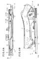
- Fig. 1 is a perspective view of a seat (a seat apparatus) for a vehicle according to a first embodiment disclosed here;
- Fig. 2A is a plan view illustrating a seat slide mechanism and a side frame according to the first embodiment disclosed here;
- Fig. 2B is a side view illustrating the seat slide mechanism and the side frame according to the first embodiment disclosed here;
- Fig. 3 is a cross sectional view taken along the line III-III in Fig. 2A and illustrating a fixing structure between an upper rail and the side frame according to the first embodiment disclosed here;
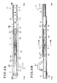
- Fig. 4 is a perspective view of the seat slide mechanism according to a second embodiment disclosed here;
- Fig. 5 is an exploded perspective view illustrating the seat slide mechanism and a lock mechanism according to the second embodiment disclosed here;
- Fig. 6A is a plan view of the seat slide mechanism according to the second embodiment disclosed here;
- Fig. 6B is a side view of the seat slide mechanism according to the second embodiment disclosed here;
- Fig. 7A is a cross sectional view taken along the line VIIA-VIIA in Fig. 6A and illustrating the seat slide mechanism and the lock mechanism according to the second embodiment disclosed here;
- Fig. 7B is a cross sectional view taken along the line VIIB-VIIB in Fig. 6A and illustrating the seat slide mechanism and the lock mechanism according to the second embodiment disclosed here;
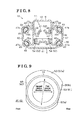
- Fig. 8 is a cross sectional view taken along the line VIII-VIII in Fig. 6B and illustrating the seat slide mechanism and the lock mechanism according to the second embodiment disclosed here;
- Fig. 9 is a configuration diagram schematically illustrating a support shaft of a lock lever and a support hole supporting the support shaft according to the second embodiment disclosed here;
- Fig. 10 is a side view illustrating the side frame of a seat cushion and a support bracket which is fixed to the side frame to support a seat back, according to a third embodiment disclosed here;
- Fig. 11 is a side view of a portion adjacent to a lower end portion of the support bracket according to the third embodiment disclosed here;
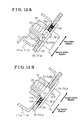
- Fig. 12A is a cross sectional view taken along the line XIIA-XIIA in Fig. 10 and illustrating a fixing structure between the side frame and the support bracket according to the third embodiment disclosed here;
- Fig. 12B is a cross sectional view taken along the line XIIB-XIIB in Fig. 10 and illustrating the fixing structure between the side frame and the support bracket according to the third embodiment disclosed here;
- Fig. 13A is a cross sectional view taken along the line XIIIA-XIIIA in Fig. 11 and illustrating an insertion hole formed at the lower end portion of the support bracket according to the third embodiment disclosed here;
- Fig. 13B is a cross sectional view taken along the line XIIIB-XIIIB in Fig. 11 and illustrating an insertion hole formed at the lower end portion of the support bracket according to the third embodiment disclosed here;
- Fig. 14 is an explanatory drawing illustrating a function of a vibration proof structure according to the third embodiment.
- Fig 15 is a perspective view of the seat (the seat apparatus) according another example of the embodiments disclosed here.
- a seat 1 for a vehicle includes a seat cushion 2 and a seat back 3 arranged at a rear end portion 2a of the seat cushion 2 so as to tilt relative to the rear end portion 2a.
- Two lower rails 5 extending in a front and rear direction of the vehicle are arranged in parallel with each other via base brackets 4, respectively, on a floor portion F of the vehicle.
- Upper rails 6 movable relative to the lower rails 5 in the front and rear direction are mounted on the lower rails 5.
- the seat 1 is supported on a seat slide mechanism 10 configured by the lower rails 5 and the upper rails 6.
- a bilateral pair of side frames 11 configuring a frame of the seat cushion 2 of the seat 1 is fixed to the upper rails 6, respectively, thereby enabling the seat 1 to move along with the upper rails 6 in the front and rear direction.
- a function of the seat slide mechanism 10 is utilized; thereby, a position of the seat 1 is adjustable in the front and rear direction.
- each of the upper rails 6 includes a ceiling plate portion 12 formed at an upper end portion (at an end portion at an upper side in Fig. 3 ) so as to have a substantially planar shape.
- Bottom plate portions 13 and 14 having substantially planar shapes are formed at each of the side frames 11 of the seat 1 (the seat cushion 2) and are positioned adjacent to end portions of the side frame 11, which are at front and rear sides of the vehicle (at right and left sides in Fig. 3 ).
- the ceiling plate portion 12 and the bottom plate portions 13 and 14 are fastened to one another by bolts 15 (i.e., serving as fixing members) and nuts 16 (i.e., serving as the fixing members); thereby, the upper rail 6 and the side frame 11 are fixed to each other so as to integrally move in the front and rear direction.
- bolts 15 i.e., serving as fixing members
- nuts 16 i.e., serving as the fixing members
- a through hole 21 is formed in the bottom plate portion 13 of the side frame 11 at the front side of the vehicle while through holes 22 and 23 are formed in the bottom plate portion 14 of the side frame 11 at the rear side of the vehicle.
- Through holes 25, 26, and 27 corresponding to the through holes 21, 22, and 23 are formed in the ceiling plate portion 12 of the upper rail 6.
- the bolts 15 are attached and inserted from a lower side of the ceiling plate portion 12 (from a lower side in Fig.
- each of the bots 15 includes a bolt head 29 and the threaded shaft 28.
- the threaded shaft 28 includes a large-diameter portion 28a at which thread grooves (thread ridges) are not formed.
- the large-diameter portion 28a is arranged at an end portion of the bolt 15, which is adjacent to the bolt head 29.
- An axial end (a lower end portion as seen in Fig. 3 ) of each of the nuts 16 screwed with the bolts 15 is brought into contact with an axial end portion (an upper end portion as seen in Fig. 3 ) of the large-diameter portion 28a, therefore positioning the nut 16 to a predetermined portion on the threaded shaft 28.
- the large-diameter portion 28a is provided at the threaded shaft 28 so as to serve as a positioning means; thereby, the nut 16 and the bolt head 29 which correspond to a pair of flanged portions are provided in separated positions between which the ceiling plate portion 12 serving as a fixed portion of the upper rail 6 and the bottom plate portions 13 and 14 serving as fixed portions of the side frame 11 are arranged.
- an outer diameter D0 of the large-diameter portion 28a, an inner diameter D1 of each of the through holes 21, 22, 23 through which the large-diameter portion 28a is inserted, and an inner diameter D2 of each of the through holes 25, 26, and 27 through which the large-diameter portion 28a is inserted are designed to be values in such a way that each of the bottom plate portions 13 and 14 of the side frame 11 is movable relative to the ceiling plate portion 12 of the upper rail 6 between the nut 16 and the bolt head 29 of the bolt 15.
- the inner diameter D1 of each of the through holes 21, 22, and 23 of the side frame 11 is designed to be slightly greater than the outer diameter D0 of the large-diameter portion 28a.
- the inner diameter D2 of each of the through holes 25, 26, and 27 of the upper rail 6 is designed to be substantially equal to the outer diameter D0 of the large-diameter portion 28a. Therefore, the upper rail 6 and the side frame 11 are allowed to move relative to each other along an axial direction of the bolt 15 and are fixed to each other so as not to move relative to each other in a direction along the floor portion F, which includes the front and rear direction and a width direction of the vehicle.
- disc springs 30 each serving as an elastic member are arranged together with the ceiling plate portion 12 of the upper rail 6 and the bottom plate portions 13 and 14 of the side frame 11, between the nuts 16 and the bolt heads 29 of the bolts 15.
- the disc spring 30 is arrange between the ceiling plate portion 12 and the bottom plate portion 13 in a manner to be compressed by a fastening force by the bolt 15 and the nut 16.
- the disc spring 30 is arranged between the nut 16 and the bottom plate portion 14 in a manner to be compressed by the fastening force.
- the side frame 11 serving as a support member is arranged on the upper rail 6 and is fixed to the upper rail 6 serving as a rail member, via the bottom plate portions 13 and 14 which are arranged at portions at the front and rear sides of the vehicle to serve as the fixed portions relative to the upper rail 6.
- the seat cushion 2 tilts in a manner that one of the rear end portion 2a and a front end portion 2b of the seat cushion 2 is moved upward and the other of the rear end portion 2a and the front end portion 2b is moved downward. Therefore, in the stationary portions ⁇ 1 and ⁇ 2 between the upper rail 6 and the side frame 11, the respective fixed portions of the upper rail 6 and the side frame 11, i.e., the ceiling plate portion 12 of the upper rail 6 and each of the bottom plate portions 13 and 14 of the side frame 11 move relative to one another along the axial direction of the bolt 15.
- the seat cushion 2 tilts in a manner that the rear end portion 2a is moved upward and the front end portion 2b is moved downward. Therefore, in the stationary portion ⁇ 1 at the front side of the vehicle, the bottom plate portion 13 corresponding to the fixed portion of the side frame 11 moves downward, that is, the bottom plate portion 13 moves relative to the ceiling plate portion 12 in a direction in which the bottom plate portion 13 comes close to the ceiling plate portion 12 corresponding to the fixed portion of the upper rail 6.
- the bottom plate portion 14 corresponding to the fixed portion of the side frame 11 moves upward, that is, the bottom plate portion 14 moves relative to the ceiling plate portion 12 in a direction in which the bottom plate portion 14 separates from the ceiling plate portion 12 corresponding to the fixed portion of the upper rail 6.
- a direction in which each of the bottom plate portions 13 and 14 of the side frame 11 moves relative to the ceiling plate portion 12 of the upper rail 6 at the time when the seat cushion 2 moves forward is defined as a first relative direction.
- the disc springs 30 each serving as the elastic member are arranged between the ceiling plate portion 12 and the bottom plate portion 13 in the first relative direction and between the bottom plate portion 14 and the nut 16 in the first relative direction.
- a direction in which the bottom plate portion 13 of the side frame 11 moves downward in accordance with the forward movement of the seat cushion 2, i.e., the direction in which the bottom plate portion 13 comes close to the ceiling plate portion 12 of the upper rail 6, corresponds to the first relative direction.
- the bolt head 29 provided below the ceiling plate portion 12 and serving as the flanged portion restricts the bottom plate portion 13 from moving downward via the ceiling plate portion 12, therefore forming a first restriction wall W1 which may restrict the bottom plate portion 13 from moving in the first relative direction.
- the disc spring 30 is arranged between the bottom plate portion 13 serving as a first member and the ceiling plate portion 12 provided in the first relative direction of the bottom plate portion 13.
- a direction in which the bottom plate portion 14 of the side frame 11 moves upward in accordance with the forward movement of the seat cushion 2, i.e., the direction in which the bottom plate portion 14 separates from the ceiling plate portion 12 of the upper rail 6, corresponds to the first relative direction.
- the nut 16 provided above the bottom plate portion 14 and serving as the flanged portion restricts the bottom plate portion 14 from moving upward, therefore forming the first restriction wall W1 which may restrict the bottom plate portion 14 from moving in the first relative direction.
- the disc spring 30 is arranged between the nut 16 forming the first restriction wall W1 and the bottom plate portion 14 serving as the first member.
- the bottom plate portions 13 and 14 each corresponding to the fixed portion of the side frame 11 to serve as the first member move in the first relative direction while compressing the disc springs 30 serving as the elastic members.
- a resistance force is applied by the elastic force of the disc springs 30 to the bottom plate portions 13 and 14 moving in the first relative direction.
- the disc spring 30 arranged at the stationary portion ⁇ 1 at the front side of the vehicle presses the bottom plate portion 13 as the first member, upward by means of the elastic force (i.e., the bottom plate portion 13 is pressed by the disc spring 30 in a direction in which the bottom plate portion 13 separates from the ceiling plate portion 12 as the second member).
- the disc spring 30 arranged at the stationary portion ⁇ 2 at the rear side of the vehicle presses the bottom plate portion 14 as the first member, downward by means of the elastic force (i.e., the bottom plate portion 14 is pressed by the disc spring 30 in a direction in which the bottom plate portion 14 comes close to the ceiling plate portion 12 as the second member).
- the resistance force (a force disturbing a relative movement of the bottom plate portions 13 and 14 to the ceiling plate portion 12) is applied by the disc springs 30 to the bottom plate portions 13 and 14 moving in the first relative direction. Therefore, an energy generated by the forward movement of the seat cushion 2 serving as the seat element is decreased; thereby, vibrations of the seat 1 may be reduced.
- the seat cushion 2 moves rearward (i.e., at the time of a rearward movement of the seat cushion 2), the seat cushion 2 tilts in a manner that the front end portion 2b is moved upward and the rear end portion 2a is moved downward. Therefore, in the stationary portion ⁇ 1 at the front side of the vehicle, the bottom plate portion 13 serving as the fixed portion of the side frame 11 moves upward, that is, the bottom plate portion 13 moves relative to the ceiling plate portion 12 in the direction in which the bottom plate portion 13 separates from the ceiling plate portion 12 serving as the fixed portion of the upper rail 6.
- the bottom plate portion 14 serving as the fixed portion of the side frame 11 moves downward, that is, the bottom plate portion 14 moves relative to the ceiling plate portion 12 in the direction in which the bottom plate portion 14 comes close to the ceiling plate portion 12 serving as the fixed portion of the upper rail 6.
- a direction in which each of the bottom plate portions 13 and 14 of the side frame 11 moves relative to the ceiling plate portion 12 of the upper rail 6 at the time of the rearward movement of the seat cushion 2 is defined as a second relative direction.
- the disc spring 30 is not provided in the second relative direction of each of the bottom plate portions 13 and 14.
- a direction in which the bottom plate portion 13 of the side frame 11 moves upward in accordance with the rearward movement of the seat cushion 2, i.e., the direction in which the bottom plate portion 13 separates from the ceiling plate portion 12 of the upper rail 6, corresponds to the second relative direction.
- the nut 16 provided above the bottom plate portion 13 and serving as the flanged portion restricts the bottom plate portion 13 from moving upward, therefore forming a second restriction wall W2 which may restrict the bottom plate portion 13 from moving in the second relative direction.
- the bottom plate portion 13 is biased upward, i.e., in the second relative direction, by the elastic force of the disc spring 30 arranged below the bottom plate portion 13, thereby being brought in advance in contact with the nut 16 forming the second restriction wall W2.
- a direction in which the bottom plate portion 14 of the side frame 11 moves downward in accordance with the rearward movement of the seat cushion 2, i.e., the direction in which the bottom plate portion 14 comes close to the ceiling plate portion 12 of the upper rail 6, corresponds to the second relative direction.
- the bolt head 29 provided below the ceiling plate portion 12 and serving as the flanged portion restricts the bottom plate portion 14 from moving downward via the ceiling plate portion 12, therefore forming the second restriction wall W2 which may restrict the bottom plate portion 14 from moving in the second relative direction.
- the bottom plate portion 14 is biased downward, i.e., in the second relative direction, by the elastic force of the disc spring 30 arranged above the bottom plate portion 14, thereby being brought in advance in contact with the ceiling plate portion 12 serving as the second member.
- the bottom plate portions 13 and 14 each corresponding to the first member do not receive the resistance force of the disc springs 30. Therefore, the bottom plate portions 13 and 14 are respectively in contact with the nut 16 forming the second restriction wall W2 and with the ceiling plate portion 12. Consequently, the bottom plate portions 13 and 14 may be promptly restricted from moving in the second relative direction by the nut 16 and the bolt head 29 which serve as the second restriction walls W2. As a result, the rearward movement of the seat cushion 2 is restricted in the first embodiment; thereby, the seat 1 may secure a high rigidity for a rear side thereof.
- the ceiling plate portion 12 as the fixed portion of the upper rail 6 and the bottom plate portions 13 and 14 as the fixed portions of the side frame 11 are fastened to one another by the bolts 15 and the nuts 16.
- the disc springs 30 each serving as the elastic member are arranged together with the bottom plate portions 13 and 14 each serving as the first member and the ceiling plate portion 12 serving as the second member, between the nuts 16 and the bolt heads 29 of the bolts 15.
- the disc spring 30 applies the resistance force to each of the bottom plate portions 13 and 14.
- the disc spring 30 is positioned so as not to apply the resistance force to each of the bottom plate portions 13 and 14.
- the side frame 11 serving as the support member and including the bottom plate portions 13 and 14 as the fixed portions relative to the upper rail 6 is fixed to the upper rail 6 so as to be positioned thereon. Therefore, in a case where the seat cushion 2 corresponding to the seat element of the seat 1 moves in the front and rear direction of the vehicle, the seat cushion 2 tilts in a manner that one of the rear end portion 2a and the front end portion 2b of the seat cushion 2 is moved upward and the other of the rear end portion 2a and the front end portion 2b is moved downward. Consequently, each of the bottom plate portions 13 and 14 of the side frame 11 moves relative to the ceiling plate portion 12 of the upper rail 6 along the axial direction of the bolt 15 so as to separate from the ceiling plate portion 12 or so as to come close to the ceiling plate portion 12.
- the disc spring 30 is arranged in the first relative direction of each of the bottom plate portions 13 and 14; thereby, the resistance force based on the elastic force of the disc spring 30 is applied to each of the bottom plate portions 13 and 14 at the time of the forward movement of the seat cushion 2. That is, the disc spring 30 functions as a resistance force applying portion. Therefore, the energy generated by the forward movement of the seat cushion 2 serving as the seat element is decreased and thus the vibrations of the seat 1 may be reduced.
- each of the bottom plate portions 13 and 14 moving in the second relative direction does not receive the resistance force of the disc spring 30. Therefore, each of the bottom plate portions 13 and 14 may be promptly restricted from moving in the second relative direction by the nut 16 or the bolt head 29 serving as the second restriction wall W2. As a result, the rearward movement of the seat cushion 2 is restricted and the seat 1 may secure the high rigidity for the rear side thereof.
- the bolt head 29 or the nut 16 which is placed in the first relative direction from the bottom plate portion 13 or 14 functions as the first restriction wall W1; thereby, the bottom plate portion 13 or 14 may be restricted from moving relative to the ceiling plate portion 12 in the first relative direction.
- the seat 1 may obtain a desired rigidity for a front side thereof.
- the bolt 15 and the nut 16 are applied as a fixation structure in which the ceiling plate portion 12 of the upper rail 6, each of the bottom plate portions 13 and 14 of the side frame 11, and the disc spring 30 are arranged between the bolt 15 and the nut 16. Therefore, the nut 16 and the bolt head 29 serve as the pair of flanged portions and thus the first restriction wall W1 and the second restriction wall W2 may be easily formed.
- the disc spring 30 is arranged between the bottom plate portion 13 and the ceiling plate portion 12 positioned below the bottom plate portion 13. Meanwhile, in the stationary portion ⁇ 2 between the ceiling plate portion 12 of the upper rail 6 and the bottom plate portion 14 of the side frame 11 at the rear side of the vehicle, the disc spring 30 is arranged between the bottom plate portion 14 and the nut 16 positioned above the bottom plate portion 14.
- the direction in which the bottom plate portion 13 moves downward in accordance with the forward movement of the seat cushion 2, i.e., the direction in which the bottom plate portion 13 comes close to the ceiling plate portion 12 of the upper rail 6, corresponds to the first relative direction.
- the direction in which the bottom plate portion 13 moves upward in accordance with the rearward movement of the seat cushion 2, i.e., the direction in which the bottom plate portion 13 separates from the ceiling plate portion 12 of the upper rail 6, corresponds to the second relative direction.
- the direction in which the bottom plate portion 14 moves upward in accordance with the forward movement of the seat cushion 2, i.e., the direction in which the bottom plate portion 14 separates from the ceiling plate portion 12 of the upper rail 6, corresponds to the first relative direction.
- the direction in which the bottom plate portion 14 moves downward in accordance with the rearward movement of the seat cushion 2, i.e., the direction in which the bottom plate portion 14 comes close to the ceiling plate portion 12 of the upper rail 6, corresponds to the second relative direction.
- the stationary portions ⁇ 1 and ⁇ 2 between the side frame 11 and the upper rail 6 are arranged at the portions at the front and rear sides of the vehicle, respectively, in which the first relative direction and the second relative direction are opposite from each other. Therefore, the energy generated by the forward movement of the seat cushion 2 may be further effectively reduced while the rearward movement of the seat cushion 2 is restricted. As a result, the vibrations of the seat 1 may be reduced while the seat 1 may secure the high rigidity for the rear side thereof.
- the disc spring 30 is arranged between the bolt 15 and the nut 16 while being compressed by the fastening force of the bolt 15 and the nut 16. Therefore, each of the bottom plate portions 13 and 14 is biased in advance in the second relative direction by the elastic force of the disc spring 30; thereby, the rearward movement of the seat cushion 2 may be further promptly restricted. As a result, the seat 1 may secure the high rigidity for the rear side thereof.
- the threaded shaft 28 of the bolt 15 includes the large-diameter portion 28a at which the thread grooves (thread ridges) are not formed.
- the large-diameter portion 28a is arranged at the end portion of the bolt 15, which is adjacent to the bolt head 29.
- the nut 16 may be easily provided in the predetermined portion on the threaded shaft 28. Therefore, the bolt head 29 which serves as the first restriction wall W1 or the second restriction wall W2 and the nut 16 which serves as the first restriction wall W1 or the second restriction wall W2 may be appropriately provided in the separated positions and assembling between the bolt 15 and the nut 16 may be simplified.
- the seat slide mechanism 10 of the second embodiment includes the lower rail 5 and the upper rail 6 that are provided movable relative to each other.
- the lower rail 5 includes a bottom wall portion 41 having a planar shape and serving as a fixed portion relative to the floor portion F of the vehicle (relative to the base bracket 4, see Fig. 1 ).
- Exterior wall portions 42 are formed at both ends of the bottom wall portion 41 in a width direction thereof (in a right and left direction in Fig. 8 ) so as to stand upward from the ends of the bottom wall portion 41.
- Upper wall portions 43 each formed in a flange are formed at respective upper ends (end portions at an upper side in Fig. 8 ) of the exterior wall portions 42 so as to extend inward from the upper ends of the exterior wall portions 42 in a width direction of the lower rail 5.
- Folded portions 44 are formed at respective ends of the upper wall portions 43 so as to be folded downward therefrom.
- the upper rail 6 includes a pair of side wall portions 45 provided to face each other in a width direction of the upper rail 6, and the ceiling plate portion 12 connecting upper ends of the side wall portions 45 to each other.
- Folded portions 46 are formed at respective lower ends of the side wall portions 45 so as to be folded outward therefrom in the width direction.
- the upper rail 6 is mounted to the lower rail 5 in a manner that an approximately U-shaped cross section formed by the pair of side wall portions 45 and the ceiling plate portion 12 is arranged between a pair of folded portions 44 of the lower rail 5.
- Each of the folded portions 46 of the upper rail 6 is formed at the lower end of each of the side wall portions 45 so as to protrude upward from the lower end along each of the exterior wall portions 42 of the lower rail 5 and so as to face the exterior wall portion 42 in the width direction.
- Curved recessed surfaces 46a and 46b extending in a direction in which the upper rail 6 extends are formed at the folded portion 46 so as to be provided in positions which face a connected portion (a curved portion 47a) between the bottom wall portion 41 and the exterior wall portion 42 of the lower rail 5 and a connected portion (a curved portion 47b) between the exterior wall portion 42 and the upper wall portion 43 of the lower rail 5.
- rollers 48 each formed in a ball are arranged between the curved recessed surface 46a and the curved portion 47a and between the curved recessed surface 46b and the curved portion 47b; thereby, the lower rail 5 and the upper rail 6 may be configured to smoothly move relative to each other along the longitudinal direction.
- the rollers 48 are rotatably held by a holder 49 formed in a bar, so as to be accommodated within both end portions of the holder 49.
- the rollers 48 within the holder 49, and the holders 49 are attached between the lower rail 5 and the upper rail 6, thereby being configured to slidably roll on respective curved surfaces of the curved portions 47a and 47b of the lower rail 5 and on the curved recessed surfaces 46a and 46b of the upper rail 6.
- the seat slide mechanism 10 is provided with a lock mechanism 50 which may restrict or lock a relative movement between the lower rail 5 and the upper rail 6.
- the lock mechanism 50 includes a support shaft 51 and a lock lever 52 rotating about the support shaft 51.
- support holes 53 facing each other are formed at the side wall portions 45, respectively, of the upper rail 6.
- the support shaft 51 is provided between the side wall portions 45 so as to extend therebetween in a manner that both end portions of the support shaft 51 are inserted in the support holes 53, respectively.
- the lock lever 52 formed in an elongated plate includes a pair of side plate portions 54 and an upper plate portion 55 connecting respective upper end portions of the side plate portions 54.
- Through holes 56 facing each other are formed at the side plate portions 54, respectively.
- the support shaft 51 is inserted in the through holes 56 formed at the side plate portions 54; thereby, the lock lever 52 is supported to rotate about the support shaft 51.
- a lock portion 57 outer shape of which is an approximately planar shape is arranged at a first end 52a of the lock lever 52 so as to extend outward in a width direction thereof.
- Through holes 58 into which the lock portion 57 is insertable are formed at the side wall portions 45, respectively, of the upper rail 6 and are provided in positions which correspond to the first end 52a of the lock lever 52.
- Plural engagement pawls 59 protruding downward are formed at each of the folded portions 44 of the lower rail 5 so as to form a comb shape.
- Plural engagement holes 60 engageable with the engagement pawls 59, respectively, of the lower rail 5 are formed at end portions of the lock portion 57 in the width direction.
- the lock portion 57 is inserted in the through holes 58; thereby, the end portions of the lock portion 57 are provided outward relative to the approximately U-shaped cross section formed by the side wall portions 45 and the ceiling plate portion 12.
- the lock mechanism 50 of the second embodiment is configured as follows.
- the lock lever 52 supported via the support shaft 51 by the upper rail 6 rotates and the lock portion 57 arranged at the first end 52a therefore moves upward; thereby, the engagement holes 60 of the lock portion 57 are engaged with the engagement pawls 59 of the lower rail 5.
- the relative movement between the lower rail 5 and the upper rail 6 may be restricted.
- the lock mechanism 50 of the second embodiment includes a spring member 61 formed by a wire rod which is processed by bending.
- the spring member 61 includes a coil portion 62 and a first extending portion 63.
- the coil portion 62 is positioned at a radially outward side of the support shaft 51 in a manner to be wounded around the support shaft 51.
- the first extending portion 63 is continuously formed with the coil portion 62 so as to extend toward the first end 52a of the lock lever 52 (toward a right side in Fig. 7A ) and so as to be arranged between the side plate portions 54 of the lock lever 52.
- a through hole 65 is formed at the upper plate portion 55 of the lock lever 52 so as to be positioned above the support shaft 51.
- the spring member 61 includes a second extending portion 66.
- the spring member 61 is inserted through the through hole 65 into the lock lever 52; thereby, the second extending portion 66 extends from the coil portion 62 to a second end 52b of the lock lever 52 (to a left side in Fig. 7A ).
- the spring member 61 of the second embodiment is configured as a torsional coil spring.
- the first extending portion 63 of the spring member 61 is provided in contact with the upper plate portion 55 of the lock lever 52 from a lower side thereof (from a lower side in Fig. 7A ).
- the second extending portion 66 of the spring member 61 is provided in contact with the ceiling plate portion 12 of the upper rail 6 from the lower side thereof (from the lower side in Fig. 7A ).
- the lock lever 52 is rotatably biased by a biasing force of the spring member 61 in a direction to move the first end 52a upward (to an upper side in Fig. 7A ).
- the lock mechanism 50 of the second embodiment includes an operation lever 67, an end portion 67a of which is inserted from a front opening portion 6a of the upper rail 6 into the upper rail 6.
- the end portion 67a of the operation lever 67 is provided in contact with the second end 52b of the lock lever 52.
- the end portion 67a is provided in contact with the upper plate portion 55 of the lock lever 52 from the lower side thereof.
- the second extending portion 66 of the spring member 61 is configured to extend so that an end 66a thereof is positioned at the front side of the vehicle with respect to the second end 52b of the lock lever 52, i.e., so that the end 66a is positioned adjacent to the front opening portion 6a of the upper rail 6.
- the operation lever 67 is configured so that a portion thereof (the end portion 67a) is inserted in the upper rail 6 and a lower side of the inserted portion (the end portion 67a) is supported by the end 66a of the second extending portion 66.
- the operation lever 67 is configured so that an operation portion thereof which is arranged at an outside of the upper rail 6 is operated; thereby, the end portion 67a inserted within the upper rail 6 moves upward.
- the end portion 67a moves upward
- the second end 52b of the lock lever 52 is lifted upward by the end portion 67a; thereby, the lock lever 52 rotates in a direction to move the first end 52a downward. Therefore, an engagement between the engagement holes 60 of the lock lever 52 and the engagement pawls 59 of the lower rail 5 are released; thereby, the relative movement of the lower rail 5 and the upper rail 6 is allowed.
- a vertical surface 68 is formed at an inner surface of each of the support holes 53 formed at the side wall portions 45 of the upper rail 6, so as to be in a position which is at the front side (at a left side in Fig. 9 ) of the vehicle with respect to the support shaft 51 inserted in the support holes 53.
- the vertical surface 68 extends along an upper and lower direction and substantially in perpendicular to the front and rear direction of the vehicle along which the upper rail 6 extends.
- an inclined surface 69 is formed at the inner surface of the support hole 53 so as to be in a position which is at the rear side (at a right side in Fig.
- the inclined surface 69 is inclined relative to the front and rear direction.
- the inclined surface 69 includes an inclination in a manner that a lower end portion 69a of the inclined surface 69 is positioned at the front side of the vehicle relative to an upper end portion 69b of the inclined surface 69.
- a profile of the support hole 53 is designed to allow the support shaft 51 to move between the vertical surface 68 and the inclined surface 69.
- the support hole 53 is formed to have an elongated hole shape so that an inner diameter thereof in the upper and lower direction is greater than a diameter of the support shaft 51, i.e., the support hole 53 has the profile in a manner that an inner diameter thereof in the front and rear direction of the vehicle increases from a lower portion to an upper portion of the support hole 53. Therefore, the support shaft 51 is allowed to move relative to the support hole 53 therewithin in the upper and lower direction. In addition, the support shaft 51 is allowed to move relative to the support hole 53 in the front and rear direction between the vertical surface 68 and the inclined surface 69 within the support hole 53 while moving to an upper side of the support hole 53.
- the coil portion 62 of the spring member 61 is arranged at the radially outward side of the support shaft 51 so as to be wounded therearound as described above (see Fig. 7A ). That is, the support shaft 51 is biased downward by the elastic force of the spring member 61 serving as the torsional coil spring, thereby being positioned at a lower side of the support hole 53 therewithin in a manner to be provided between the vertical surface 68 at the front side of the vehicle and the inclined surface 69 at the rear side of the vehicle.
- the relative movement between the lower rail 5 and the upper rail 6 is restricted by the engagement between the engagement pawls 59 arranged at the lower rail 5 and the engagement holes 60 arranged at the upper rail 6.
- the support shaft 51 supporting the lock lever 52 apparently moves relative to the support holes 53 in the front and rear direction within the support holes 53 into which the support shaft 51 is inserted.
- the upper rail 6 (the side wall portions 45 of the upper rail 6) in which the support holes 53 are formed moves integrally with the seat cushion 2 supported by the upper rail 6.
- the lower rail 5 moves integrally with the floor portion F (with the base bracket 4, see Fig. 1 ) to which the lower rail 5 is fixed.
- the lock lever 52 rotating about the support shaft 51 supported by the upper rail 6 is in a state where the engagement holes 60 are engaged with the engagement pawls 59 of the lower rail 5.
- the support shaft 51 apparently moves relative to the support holes 53 therewithin toward the rear side of the vehicle.
- the support shaft 51 apparently moves relative to the support holes 53 therewithin toward the front side of the vehicle.
- the support shaft 51 configures the first member and each of the side wall portions 45 of the upper rail 6 configures the second member.
- the inner wall surface of each of the support holes 53 configures the first restriction wall W1 and the second restriction wall W2.
- a direction in which the support shaft 51 apparently moves within the support hole 53 to the rear side of the vehicle corresponds to the first relative direction while a direction in which the support shaft 51 apparently moves within the support hole 53 to the front side of the vehicle corresponds to the second relative direction.
- the inclined surface 69 is formed at the support hole 53 so as to be provided in the position that is at the rear side of the vehicle with respect to the support shaft 51 within the support hole 53. Therefore, in a case where the seat cushion 2 moves forward, the support shaft 51 moves within the support hole 53 to the upper side thereof so as to slide on the inclined surface 69, thereby being allowed to move to the rear side of the vehicle. In other words, the support shaft 51 slides on the inclined surface 69, thereby receiving a resistance force while moving in the first relative direction that corresponds to the forward movement of the seat cushion 2. Furthermore, according to the second embodiment, the support shaft 51 is biased downward by the elastic force of the spring member 61. Accordingly, at the time of the forward movement of the seat cushion 2, the support shaft 51 moves in the first relative direction against the elastic force of the spring member 61.
- a resistance force is applied to the support shaft 51 moving in the first relative direction; therefore, an energy generated by the forward movement of the seat cushion 2 serving as the seat element is decreased and thus vibrations of the seat 1 may be reduced.
- the support shaft 51 is slidably moved to the upper end portion 69b of the inclined surface 69, therefore being brought into contact with an upper wall surface 53a of the support hole 53. Consequently, in the second embodiment, the support shaft 51 is restricted from moving upward; thereby, the inclined surface 69 functions as the first restriction wall W1.
- the support shaft 51 is brought into contact with the vertical surface 68 formed at the support hole 53 so as to be in the position that is at the front side of the vehicle with respect to the support shaft 51 within the support hole 53.
- the support shaft 51 moves relative to the support hole 53 toward the front side of the vehicle so as to be brought into contact with the vertical surface 68 configuring the second restriction wall W2, i.e., the support shaft 51 moves in the second relative direction corresponding to the rearward movement of the seat cushion 2.
- a specific resistance force is not applied to the support shaft 51. Therefore, according to the second embodiment, the rearward movement of the seat cushion 2 is promptly restricted and thus the seat 1 may secure the high rigidity for the rear side thereof.
- the support shaft 51 of the lock lever 52 is arranged between the side wall portions 45 of the upper rail 6 so as to extend between the side wall portions 45 in a state where the both end portions of the support shaft 51 are inserted in the support holes 53 formed at the side wall portions 45, respectively.
- the lock portion 57 is provided at the first end 52a of the lock lever 52.
- the lock portion 57 includes the plural engagement holes 60 engageable with the plural engagement pawls 59 provided at the lower rail 5.
- the engagement holes 60 serving as engaging portions engage with the engagement pawls 59 serving as engaged portions; thereby, the lock mechanism 50 restricts the relative movement between the lower rail 5 and the upper rail 6.
- the vertical surface 68 is formed at the support hole 53 so as to be in the position that is at the front side of the vehicle with respect to the support shaft 51 within the support hole 53.
- the vertical surface 68 extends along the upper and lower direction and substantially in perpendicular to the front and rear direction of the vehicle.
- the inclined surface 69 is formed at the support hole 53 so as to be in the position that is at the rear side of the vehicle with respect to the support shaft 51 within the support hole 53.
- the support hole 53 has the elongated hole shape in a manner that the inner diameter thereof in the upper and lower direction is greater than the diameter of the support shaft 51 so as to allow the support shaft 51 to move between the vertical surface 68 and the inclined surface 69 within the support hole 53.
- the support shaft 51 at the time of the forward movement of the seat cushion 2, the support shaft 51 apparently moves relative to the support hole 53 therewithin toward the rear side of the vehicle.
- the support shaft 51 moves to the upper side of the support hole 53 therewithin so as to slide on the inclined surface 69 provided at the rear side of the vehicle with respect to the support shaft 51. Therefore, the support shaft 51 receives the resistance force while moving in the first relative direction that corresponds to the forward movement of the seat cushion 2. That is, the inclined surface 69 functions as the resistance force applying portion. Therefore, the energy generated by the forward movement of the seat cushion 2 serving as the seat element is decreased and thus the vibrations of the seat 1 may be reduced.
- the support shaft 51 apparently moves relative to the support hole 53 therewithin toward the front side of the vehicle.
- the specific resistance force is not applied to the support shaft 51 in accordance with the movement of the support shaft 51 in the second relative direction corresponding to the rearward movement of the seat cushion 2. Therefore, the vertical surface 68 provided at the front side of the vehicle with respect to the support shaft 51 functions as the second restriction wall W2 to thereby promptly restrict the movement of the support shaft 51 in the second relative direction.
- the rearward movement of the seat cushion 2 is restricted and thus the seat 1 may secure the high rigidity for the rear side thereof.
- the inner surface of the support hole 53 which is positioned at the rear side of the vehicle with respect to the support shaft 51 and which includes the inclined surface 69, configures the first restriction wall W1, thereby restricting the support shaft 51 from moving relative to the support hole 53 in the first relative direction.
- the desired rigidity of the seat 1 may be secured for the front side of the seat 1.
- the support shaft 51 is biased downward by the elastic force of the spring member 61 serving as the elastic member to bias the lock lever 52 so that the lock lever 52 rotates.
- the spring member 61 serves as a biasing portion and may thereby bias the support shaft 51 in the second relative direction. Accordingly, the resistance force based on the elastic force of the spring member 61 may be applied to the support shaft 51 moving in the first relative direction. That is, the spring member 61 functions as the resistance force applying portion.
- the support shaft 51 may be brought in advance into contact with the vertical surface 68 by the spring member 61. Consequently, the rearward movement of the seat cushion 2 may be promptly restricted. As a result, the seat 1 may secure the high rigidity for the rear side thereof.
- a support bracket 70 is fixed to a rear end portion 11a of each of the side frames 11 configuring the frame of the seat cushion 2.
- a frame 72 of the seat back 3 is connected via a recliner 71 to the support bracket 70; thereby, the seat back 3 is configured to be tiltably supported by the rear end portion 2a of the seat cushion 2 (see Fig. 1 ).
- the support bracket 70 according to the third embodiment is formed substantially in a planar shape.
- the support bracket 70 is fixed to a side surface 11s of the side frame 11 by the bolts 15 serving as the fixing members and the nuts 16 serving as the fixing members.
- the support bracket 70 and the side frame 11 are fixed to each other via first and second positions which are provided at the rear end portion 11a of the side frame 11 in a separated manner in the front and rear direction and in the upper and lower direction.
- a pair of insertion holes 73 (73A, 73B) opened to the side surface 11s of the side frame 11 is formed at the side surface 11 s so as to be in the first and second positions separated in the front and rear direction and in the upper and lower direction. As illustrated in Figs.
- a pair of insertion holes 74 (74A, 74B) corresponding to the pair of insertion holes 73 (73A, 73B) of the side frame 11 is formed at a lower end portion 70a of the support bracket 70.
- the threaded shaft 28 serving as the shaft portion of each of the bolts 15 is attached to the support bracket 70 and the side frame 11 from the direction of the support bracket 70 in a manner to be inserted in each of the insertions holes 73 (73A, 73B) and 74 (74A, 74B).
- the side frame 11 and the support bracket 70 are arranged between the bolt head 29 of the bolt 15 and the nut 16 screwed with the threaded shaft 28; thereby, the support bracket 70 is fixed to the side surface 11 s of the side frame 11 by the fastening force of the bolt 15 and the nut 16.
- an inner diameter of each of the insertion holes 73 is designed to be substantially equal to a diameter of the threaded shaft 28.
- Each of the insertion holes 74 i.e., first and second insertion holes 74A, 74B
- the first insertion hole 74A is formed at the lower end portion 70a of the support bracket 70 so as to be adjacent to a front end of the lower end portion 70a.
- the second insertion hole 74B is formed at the lower end portion 70a of the support bracket 70 so as to be adjacent to a rear end of the lower end portion 70a.
- the first insertion hole 74A is provided at front and upper sides relative to the second insertion hole 74B in a state where the support bracket 70 is attached to the side frame 11.
- a first through hole 75A including a small diameter compared to a diameter of the first insertion hole 74A is formed at the support bracket 70 so as to be positioned at rear and upper sides relative to the first insertion hole 74A.
- a second through hole 75B including a small diameter compared to a diameter of the second insertion hole 74B is formed at the support bracket 70 so as to be positioned at lower and front sides relative to the second insertion hole 74B.
- the first insertion hole 74A is formed to have the elongated hole shape extending in a direction linearly connecting between the center point of the first insertion hole 74A and the center point of the first through hole 75A formed adjacent to the first insertion hole 74A.
- the second insertion hole 74B is formed to have the elongated hole shape extending in a direction linearly connecting between the center point of the second insertion hole 74B and the center point of the second through hole 75B formed adjacent to the second insertion hole 74B.
- an elastic body 77 is arranged within each of the first and second insertion holes 74A and 74B.
- the elastic body 77 covers one of end portions (first and second end portions P1 and P2) in a direction of a long side of the elongated hole shape of each of the first and second insertion holes 74A and 74B, i.e., the elastic body 77 covers an inner surface of the first end portion P1 positioned at each of the first and second through holes 75A and 75B formed adjacent to the first and second insertion holes 74A and 74B, respectively.
- shallow grooves 76 are recessed at a periphery of the first insertion hole 74A and the first through hole 75A adjacent to the first insertion hole 74A and at a periphery of the second insertion hole 74B and the second through hole 75B adjacent to the second insertion hole 74B.
- the shallow grooves 76 are formed at both surfaces of the support bracket 70.
- the elastic body 77 is formed, for example, of rubber and is provided so as to cover not only the first end portion P1 of each of the first and second insertion holes 74A and 74B but also each of the first and second through holes 75A and 75B and the shallow groove 76 adjacent to each of the first and second through holes 75A and 75B.
- the large-diameter portion 28a is formed at the end portion of the bolt 15, which is adjacent to the bolt head 29, in the same way as in the first embodiment.
- the inner diameter of each of the insertion holes 73 (73A, 73B) of the side frame 11 is designed to be substantially equal to a diameter of the large-diameter portion 28a.
- An inner diameter of each of the insertion holes 74 (74A, 74B) in a direction of a short side of the elongated hole shape of each of the insertion holes 74 (74A, 74B) is designed to be substantially equal to the diameter of the large-diameter portion 28a.
- the threaded shaft 28 of the bolt 15 is inserted in a penetrating manner in each of the insertion holes 73 (73A, 73B) of the side frame 11 and each of the insertion holes 74 (74A, 74B) of the support bracket 70 in a state where a portion of a circumferential surface of the large-diameter portion 28a is in contact with the elastic body 77.
- the support bracket 70 supporting the seat back 3 serving as the seat element is configured so that the lower end portion 70a is fixed to the side frame 11 of the seat cushion 2. Therefore, the support bracket 70 tilts about the lower end portion 70a fixed to the side frame 11, at the time of forward and rearward movements of the seat back 3 supported by the support bracket 70 thereabove.
- the support bracket 70 and the side frame 11 are fixed to each other via the first and second positions separated in the front and rear direction and in the upper and lower direction at the rear end portion 11a of the side frame 11. Therefore, at the time of the forward and rearward movements of the seat back 3, rotational moment (acting in a direction of each arrow indicated by a dashed line in Fig. 14 ) is generated about a substantial intermediate portion (i.e., serving as a rotation center P0) between stationary portions ⁇ 3 and ⁇ 4 of the support bracket 70 relative to the side frame 11.
- each of the insertion holes 73 (73A, 73B) of the side frame 11 is designed to be substantially equal to the diameter of the threaded shaft 28 (the large-diameter portion 28a) of the bolt 15 as described above. Accordingly, the threaded shaft 28 inserted in each of the insertion holes 73 (73A, 73B) and serving as the shaft portion may not move relative to the side frame 11 in a direction in which the rotational moment is generated.
- each of the insertion holes 74 (74A, 74B) of the support bracket 70 is formed to have the elongated hole shape extending in a direction substantially identical to the direction in which the rotational moment is generated, i.e., in a direction in which the threaded shaft 28 moves relative to each of the insertion holes 74 (74A, 74B) therewithin at the time of the forward and rearward movements of the seat back 3 (the direction in which the threaded shaft 28 moves relative to each of the insertion holes 74 (74A, 74B) therewithin at the time of the forward and rearward movements of the seat back 3 is opposite from the direction in which the rotational moment is generated).
- the threaded shaft 28 apparently moves relative to each of the insertion holes 74 (74A, 74B) therewithin along the direction of the long side of each of the insertion holes 74 (74A, 74B) in which the threaded shaft 28 is inserted.
- the threaded shafts 28 respectively inserted in the first insertion hole 74A and the second insertion hole 74B move therewithin toward the first through hole 75A and the second through hole 75B that are positioned adjacent to the first insertion hole 74A and the second insertion hole 74B. That is, the threaded shaft 28 within the first insertion hole 74A configuring the stationary portion ⁇ 3 at the front side of the vehicle moves relative to the first insertion hole 74A in an upper right direction seen in Fig. 14 . In addition, the threaded shaft 28 within the second insertion hole 74B configuring the stationary portion ⁇ 4 at the rear side of the vehicle moves relative to the second insertion hole 74B in a lower left direction seen in Fig. 14 .
- the threaded shafts 28 within the first insertion hole 74A and the second insertion hole 74B that have the elongated hole shapes apparently move within the first insertion hole 74A and the second insertion hole 74B in directions opposite from the first through hole 75A and the second through hole 75B. That is, the threaded shaft 28 within the first insertion hole 74A configuring the stationary portion ⁇ 3 at the front side of the vehicle moves relative to the first insertion hole 74A in the lower left direction seen in Fig. 14 . In addition, the threaded shaft 28 within the second insertion hole 74B configuring the stationary portion ⁇ 4 at the rear side of the vehicle moves relative to the second insertion hole 74B in the upper right direction seen in Fig. 14 .
- the threaded shaft 28 of the bolt 15 configures the first member and the support bracket 70 configures the second member.
- the first and second end portions P1 and P2 in the direction of the long side of the elongated hole shape of each of the insertion holes 74 (74A, 74B) arranged at the support bracket 70 configure the first restriction wall W1 and the second restriction wall W2, respectively.
- a direction in which the threaded shafts 28 respectively inserted in the insertion holes 74 (74A, 74B) apparently move relative to the insertion holes 74 (74A, 74B) therewithin toward the respective first end portions P1 adjacent to the first through hole 75A and the second through hole 75B corresponds to the first relative direction.
- a direction in which the threaded shafts 28 respectively inserted in the insertion holes 74 (74A, 74B) apparently move relative to the insertion holes 74 (74A, 74B) therewithin toward the respective second end portions P2 positioned opposite from the first end portions P1 in the direction of the long side of the insertion holes 74 (74A, 74B) corresponds to the second relative direction.
- the elastic body 77 is arranged at each of the insertion holes 74 (74A, 74B) as described above.
- the elastic body 77 covers the first end portion P1 positioned in the first relative direction in the direction of the long side of each of the insertion holes 74 (74A, 74B) (see Figs. 12A, 12B , 13A, and 13B ). Accordingly, at the time of the forward movement of the seat back 3, the threaded shaft 28 moves in the first relative direction within each of the insertion holes 74 (74A, 74B) while compressing the elastic body 77 arranged between the threaded shaft 28 and the first end portion P1 configuring the first restriction wall W1.
- a resistance force is applied to the threaded shaft 28 moving in the first relative direction, by an elastic force of the elastic body 77 positioned between the threaded shaft 28 and the first end portion P1 provided at one side in the direction of the long side of each of the insertion holes 74 (74A, 74B), i.e., the elastic body 77 serves as the resistance force applying portion. Therefore, an energy generated by the forward movement of the seat back 3 corresponding to the seat element is decreased and thus vibrations of the seat 1 may be reduced.
- the threaded shaft 28 is brought into contact with the second end portion P2 positioned in the second relative direction from the threaded shaft 28 and provided at the other side in the direction of the long side of each of the insertion holes 74 (74A, 74B).
- the elastic body 77 is not compressed by the movement of the threaded shaft 28 in the second relative direction within each of the insertion holes 74 (74A, 74B). That is, a specific resistance force is not applied to the threaded shaft 28 when the threaded shaft 28 moves in the second relative direction within each of the insertion holes 74 (74A, 74B).
- the rearward movement of the seat back 3 is promptly restricted and thus the seat 1 may secure the high rigidity for the rear side thereof.
- the support bracket 70 supporting the seat back 3 is fixed to the side surface 11 s of the side frame 11 configuring the frame of the seat cushion 2, by means of the bolts 15 serving as the fixing members and the nuts 16 serving as the fixing members.
- the threaded shaft 28 of each of the bolts 15 is inserted in each of the insertion holes 73 (73A, 73B) formed at the side frame 11 and in each of the insertion holes 74 (74A, 74B) formed at the support bracket 70.
- Each of the insertion holes 73 (73A, 73B) of the side frame 11 includes the inner diameter substantially equal to the diameter of the large-diameter portion 28a of the threaded shaft 28.
- each of the insertion holes 74 (74A, 74B) is formed to have the elongated hole shape extending in the direction in which the threaded shaft 28 moves relative to each of the insertion holes 74 (74A, 74B) therewithin at the time of the forward and rearward movements of the seat back 3.
- the elastic body 77 is arranged at each of the insertion holes 74 (74A, 74B) of the support bracket 70. The elastic body 77 covers the first end portion P1 positioned in the first relative direction of each of the insertion holes 74 (74A, 74B).
- the threaded shaft 28 moves in the first relative direction within each of the insertion holes 74 (74A, 74B) while compressing the elastic body 77 arranged between the threaded shaft 28 and the first end portion P1.
- the resistance force is applied to the threaded shaft 28 moving in the first relative direction, by the elastic force of the elastic body 77. That is, the elastic body 77 serves as the resistance force applying portion. Therefore, the energy generated by the forward movement of the seat back 3 corresponding to the seat element is decreased and thus the vibrations of the seat 1 may be reduced.
- the threaded shaft 28 moves in the second relative direction within each of the insertion holes 74 (74A, 74B).
- the elastic body 77 is not compressed by the movement of the threaded shaft 28 in the second relative direction. Therefore, the specific resistance force is not applied to the threaded shaft 28 when the threaded shaft 28 moves in the second relative direction. Consequently, the second end portion P2 of each of the insertion holes 74 (74A, 74B), which is positioned in the second relative direction from the threaded shaft 28, serves as the second restriction wall W2; thereby, the movement of the threaded shaft 28 in the second relative direction may be promptly restricted. As a result, the seat 1 may secure the high rigidity for the rear side thereof.
- the elastic body 77 reaches a compressed limit thereof; therefore, the first end portion P1 of each of the insertion holes 74 (74A, 74B) positioned in the first relative direction from the threaded shaft 28 serves as the first restriction wall W1.
- the threaded shaft 28 is restricted from moving relative to each of the insertion holes 74 (74A, 74B) therewithin in the first relative direction; thereby, the seat 1 may obtain the desired rigidity for the front side thereof.
- the support bracket 70 is fixed to the side frame 11 via the stationary portions ⁇ 3 and ⁇ 4 at the front and rear sides of the vehicle.
- the first relative direction and the second relative direction are opposite from each other.
- the rotational moment acting about the substantial intermediate portion (i.e., serving as the rotation center P0) between the stationary portions ⁇ 3 and ⁇ 4 of the support bracket 70 relative to the side frame 11 is generated at the lower end portion 70a of the support bracket 70.
- the energy generated by the forward movement of the seat back 3 may be reduced while the rearward movement of the seat back 3 may be restricted.
- the vibrations of the seat 1 may be appropriately reduced while the seat 1 may secure the high rigidity for the rear side thereof.
- each of the first, second, and third embodiments may be utilized independently or may be utilized by an arbitrary combination thereof.
- a bilateral pair of side frames 11 configuring the frame of the seat cushion 2 is fixed to the upper rails 6, respectively.
- each of the side frames 11 configures the support member and the bottom plate portions 13 and 14 corresponding to the fixed portions of the side frame 11 configure the first members.
- a member or component different from the side frame 11 is arranged between the side frame 11 and the upper rail 6.
- the member or component arranged between the side frame 11 and the upper rail 6 may correspond to the support member and a fixed portion of the member or component may be configured as the first member.
- a base bracket 82 of the seat lift mechanism 81 serves as the support member and a fixed portion of the base bracket 82 relative to the upper rail 6 serves as the first member.
- the bolt 15 and the nut 16 are applied as the fixing members.
- a rivet may be applied as the fixing member.
- any member which includes a shaft portion penetrating through the fixed portion (the ceiling plate portion 12) of the upper rail 6 and the fixed portion (each of the bottom plate portions 13 and 14 of the side frame 11), and a pair of flanged portions arranged at the shaft portion to be in separated positions between the fixed portions is configured to fix the fixed portion of the side frame 11 to the fixed portion of the upper rail 6 and to allow the fixed portion of the side frame 11 to move relative to the fixed portion of the upper rail 6 along the shaft portion between the flanged portions.
- the member may be applied as the fixing member.
- a rivet may be applied as the fixing member.
- the member in a case where any member includes a shaft portion penetrating through the support bracket 70 and the side frame 11 and the shaft portion of the member is movable relative to each of the insertion holes 74 (74A, 74B) therewithin, the member may be applied as the fixing member.
- the large-diameter portion 28a is formed at the end portion of the bolt 15, which is adjacent to the bolt head 29.
- the large-diameter portion 28a is configured to serve as the positioning means to determine the position of the nut 16 which is to be screwed with the threaded shaft 28.
- a known positioning pin or another means may be utilized to determine the position of the nut 16.
- the disc spring 30 is applied as the elastic member arranged together with the ceiling plate portion 12 of the upper rail 6 and the bottom plate portions 13 and 14 of the side frame 11 between the nut 16 and the bolt head 29 (of the bolt 15) that serve as the flanged portions.
- the elastic member may be arbitrarily changed.
- a coil spring may be applied as the elastic member.
- the stationary portions ⁇ 1 and ⁇ 2 between the side frame 11 and the upper rail 6 are provided in the positions at the front and rear sides of the vehicle, respectively, in which the first relative direction and the second relative are opposite from each other.
- the single fixation structure formed by the bolt 15, the nut 16, and the disc spring 30 is provided in a position as the stationary portion ⁇ 1 between the ceiling plate portion 12 of the upper rail 6 and the bottom plate portion 13 of the side frame 11 at the front side of the vehicle, and the fixation structures each formed by the bolt 15, the nut 16, and the disc spring 30 are provided in two positions as the stationary portions ⁇ 2 between the ceiling plate portion 12 of the upper rail 6 and the bottom plate portion 14 of the side frame 11 at the rear side of the vehicle.
- the fixation structure according to the first embodiment may be modified as follows.
- the number of fixation structures each formed by the bolt 15, the nut 16, and the disc spring 30 and the number of first and second fixation structures, respectively, in which the first relative direction and the second relative direction are opposite from each other, may be arbitrarily changed.
- the number of stationary portions ⁇ 1 may be plural while the number of stationary portions ⁇ 2 may one.
- the number of fixation structures each formed by the bolt 15, the nut 16, and the disc spring 30 may be only one.
- the fixation structure includes the vibration proof structure according to the first embodiment, which may decrease the energy generated by the forward movement of the seat cushion 2 while restricting the rearward movement of the seat cushion 2.
- the fixation structure formed by the insertion hole 74 (74A, 74B) having the elongated hole shape, the threaded shaft 28 of the bolt 15 inserted in the insertion hole 74 (74A, 74B), and the elastic body 77 arranged in the insertion hole 74 (74A, 74B) may be arbitrarily changed.
- the number of fixation structures may be arbitrarily changed.
- the fixation structure includes the vibration proof structure according to the third embodiment, which may decrease the energy generated by the forward movement of the seat back 3 while restricting the rearward movement of the seat back 3.
- each of the insertion holes 73 (73A, 73B) of the side frame 11 includes the inner diameter substantially equal to the diameter of the large-diameter portion 28a of the threaded shaft 28.
- each of the insertion holes 74 (74A, 74B) of the support bracket 70 is formed to have the elongated hole shape extending in the direction in which the threaded shaft 28 moves relative to the insertion hole 74 (74A, 74B) therewithin at the time of the forward and rearward movements of the seat back 3.
- the insertion hole 74 (74A, 74B) of the support bracket 70 may be designed to include an inner diameter substantially equal to the diameter of the threaded shaft 28 while the insertion hole 73 (73A, 73B) of the side frame 11 may be formed to have an elongated hole shape extending in a direction in which the threaded shaft 28 moves relative to the insertion hole 73 (73A, 73B) therewithin at the time of the forward and rearward movements of the seat back 3.
- the elastic body 77 is provided within the insertion hole 73 (73A, 73B) including the elongated hole shape.
- the disc spring 30 is arranged between the bolt 15 and the nut 16 in a manner to be compressed by the fastening force of the bolt 15 and the nut 16.
- the disc spring 30 may be arranged between the bolt 15 and the nut 16 in a manner not to be compressed.
- the support shaft 51 is biased downward by the elastic force of the spring member 61 serving as the elastic member biasing the lock lever 52 to rotate the lock lever 52. Therefore, the support shaft 51 may be biased in the second relative direction by the spring member 61 serving as the biasing portion.
- the spring member 61 an elastic member different from the spring member 61 may be applied as the biasing portion.
- the inclined surface 69 serving as the resistance force applying portion is not necessarily provided.
- a configuration not including the aforementioned biasing portion is applicable.
- the support shaft 51 is brought into slidable contact with the inclined surface 69 positioned at the rear side of the vehicle with respect to the support shaft 51 and thus a predetermined resistance force may be applied to the support shaft 51 moving in the first relative direction.
- the inclination of the inclined surface 69 is designed so that the support shaft 51 moves relative to the support hole 53 toward the front side of the vehicle by gravity; thereby, the support shaft 51 may be in contact with the vertical surface 68 in advance.
- each of the engagement holes 60 is configured as the engaging portion of the lock lever 52 and each of the engagement pawls 59 is configured as the engaged portion of the lower rail 5.
- the engaging portion may be formed in a convex shape and the engaged portion may be formed in a recessed shape.
- the vertical surface 68 is provided in the position that is at the front side of the vehicle with respect to the support shaft 51 within the support hole 53.
- the vertical surface 68 extends in the upper and lower direction and substantially in perpendicular to the front and rear direction of the vehicle.
- the vertical surface 68 may not be necessarily formed at the support hole 53 as long as the support hole 53 is designed to have a profile so as to function as the second restriction wall W2 restricting the support shaft 51 from moving in the second relative direction.
Landscapes
- Engineering & Computer Science (AREA)
- Aviation & Aerospace Engineering (AREA)
- Transportation (AREA)
- Mechanical Engineering (AREA)
- Seats For Vehicles (AREA)
Abstract
Description
- This invention generally relates to a vibration proof structure of a seat apparatus for a vehicle.
- Known vibration proof structures of seat apparatuses (seats) for vehicles are disclosed, for example, in
JP2011-235727A JP2011-510863A References 1 and 2). In particular, the vibration structure according toReference 1 is an inner and outer double structure in which a lower end portion of a side frame of a seat back is configured so that an inner frame is arranged at an interior side of an outer frame. In addition, an elastic member is provided between the inner frame and the outer frame. Further, according toReference 2, the seat includes sub-frames (side frames) of a seat back and a rod connecting the side frames to each other.Reference 2 discloses a structure in which an elastic member is provided between the rod and one of the side frames. In bothReferences - As described above, according to the vibration structures of
References Reference 2, the elastic member is provided between one end portion of the rod and the side frame; thereby, the deterioration of the rigidity of the seat is restricted. In fact, the seat requires the highest rigidity for a rear side thereof; however, in this point, the vibration proof structure disclosed inReference 2 may not ensure the high rigidity for the rear side of the seat. - A need thus exists for a vibration proof structure of a seat apparatus for a vehicle, which may ensure a high rigidity for a rear side of a seat.
- According to an aspect of this invention, a vibration proof structure of a seat apparatus for a vehicle includes a first member and a second member movably arranged relative to each other in a first relative direction corresponding to a forward movement of a seat element in a front and rear direction of the vehicle and in a second relative direction corresponding to a rearward movement of the seat element in the front and rear direction of the vehicle, the seat element being supported at an upper side of the seat apparatus, a first restriction wall restricting a relative movement of the first member to the second member in the first relative direction, a second restriction wall restricting the relative movement of the first member to the second member in the second relative direction, and a resistance force applying portion applying a resistance force to the first member moving in the first relative direction between the first restriction wall and the second restriction wall while not applying the resistance force to the first member moving in the second relative direction between the first restriction wall and the second restriction wall.
- According to the aforementioned configuration, at the time of the forward movement of the seat element, the resistance force (a force disturbing the relative movement) is applied to the first member moving in the first relative direction corresponding to the forward movement of the seat element. Therefore, an energy generated by the forward movement of the seat element is decreased; thereby, vibrations of a seat may be reduced. On the other hand, at the time of the rearward movement of the seat element, a specific resistance force is not applied to the first member moving in the second relative direction corresponding to the rearward movement of the seat element. Therefore, the movement of the seat element in the second relative direction is promptly restricted by the second restriction wall and thus the seat may secure a high rigidity for a rear side thereof. In addition, in a case where the seat element moves excessively forward, the first restriction wall restricts the first member from moving in the first relative direction relative to the second member. As a result, the seat may obtain a desired rigidity for a front side thereof.
- According to another aspect of the invention, the vibration proof structure further includes a support member supporting a seat cushion, a rail member supporting the support member, and a fixation structure fixing the support member and the rail member to each other, the fixation structure including: a fixing member having a shaft portion penetrating through a fixed portion of the rail member and a fixed portion of the support member, and a pair of flanged portions arranged at the shaft portion to be provided in separated positions between which the fixed portion of the rail member and the fixed portion of the support member are arranged, the fixing member allowing the relative movement in the first relative direction and in the second relative direction and fixing the fixed portion of the rail member to the fixed portion of the support member; and an elastic member provided together with the fixed portion of the rail member and the fixed portion of the support member between the pair of flanged portions to bias the fixed portion of the support member in the second relative direction.
- In other words, the support member supporting the seat cushion is fixed to and positioned on the rail member supporting the support member. Accordingly, in a case where the seat cushion corresponding to the seat element moves in the front and rear direction of the vehicle, the seat cushion tilts in a manner that one of a rear end portion and a front end portion of the seat cushion is moved upward and the other of the rear end portion and the front end portion is moved downward. Therefore, the fixed portion of the support member moves relative to the rail member along the shaft portion configuring the fixing member, in a direction where the fixed portion of the support member comes close to the fixed portion of the rail member or in a direction where the fixed portion of the support member separates from the fixed portion of the rail member.
- Thus, according to the aforementioned configuration, at the time of a forward movement of the seat cushion, the resistance force based on an elastic force of the elastic member is applied to the fixed portion of the support member moving in the first relative direction. That is, the elastic member functions as the resistance force applying portion; thereby, an energy generated by the forward movement of the seat cushion is decreased and vibrations of the seat may be therefore reduced.
- On the other hand, at the time of a rearward movement of the seat cushion, a specific resistance force is not applied to the fixed portion of the support member moving in the second relative direction. Therefore, the movement of the support member in the second relative direction may be promptly restricted by the flanged portions configuring the second restriction walls. As a result, the rearward movement of the seat cushion is restricted and thus the seat may secure the high rigidity for the rear side thereof.
- In addition, in a case where the seat cushion moves excessively forward, the fixed portion of the support member is restricted by one of the flanged portions configuring the first restriction walls from moving in the first relative direction relative to the rail member. Therefore, the seat may obtain the desired rigidity for the front side thereof.
- According to still another aspect of the invention, the fixation structure includes first and second fixation structures provided at portions, respectively, in which the first relative direction and the second relative direction are opposite from each other.
- According to the aforementioned configuration, the energy generated by the forward movement of the seat cushion may be decreased while the rearward movement of the seat cushion is further effectively restricted. As a result, the vibrations of the seat may be appropriately reduced while the seat secures the high rigidity for the rear side thereof.
- According to a further aspect of the invention, the vibration proof structure further includes: a seat slide mechanism having a lower rail and an upper rail which are provided relatively movable to each other in the front and rear direction of the vehicle, the seat slide mechanism supporting the seat cushion; and a lock mechanism configured to restrict a relative movement between the lower rail and the upper rail. The lock mechanism includes a support shaft supported by the upper rail and a lock lever rotatable about the support shaft, the lock mechanism restricting the relative movement between the lower rail and the upper rail by engagement between an engaging portion formed at the lock lever and an engaged portion formed at the lower rail. The upper rail includes a pair of side wall portions arranged to face each other in a width direction of the upper rail. The support shaft is arranged between and extends between support holes formed at the side wall portions of the upper rail. Each of the support holes includes an inclined surface which is provided at a rear side of the vehicle with respect to the support shaft to be inclined relative to the front and rear direction of the vehicle, the support hole being formed to allow a relative movement of the support shaft to the support hole therewithin in the front and rear direction of the vehicle.
- According to the aforementioned configuration, at the time of the forward movement of the seat cushion, the support shaft apparently moves relative to the support hole therewithin toward the rear side of the vehicle. In addition, the support shaft moves relative to the support hole therewithin so as to slide on the inclined surface provided at the rear side of the vehicle with respect to the support shaft. Therefore, the support shaft receives the resistance force while moving in the first relative direction that corresponds to the forward movement of the seat cushion. That is, the inclined surface functions as the resistance force applying portion; thereby, the energy generated by the forward movement of the seat cushion serving as the seat element is decreased and thus the vibrations of the seat may be reduced.
- Meanwhile, at the time of the rearward movement of the seat cushion, the support shaft apparently moves relative to the support hole therewithin toward a front side of the vehicle. At this time, a specific resistance force is not applied to the support shaft moving in the second relative direction corresponding to the rearward movement of the seat cushion. Accordingly, an inner surface of the support hole, which is positioned at the front side of the vehicle with respect to the support shaft, functions as the second restriction wall to thereby promptly restrict the movement of the support shaft in the second relative direction. As a result, the rearward movement of the seat cushion is restricted and thus the seat may secure the high rigidity for the rear side thereof. Moreover, in a case where the seat cushion moves excessively forward, the inner surface of the support hole, which includes the inclined surface and which is positioned at the rear side of the vehicle with respect to the support shaft, functions as the first restriction wall. Therefore, the support shaft is restricted from moving in the first relative direction relative to the support hole and thus the seat may secure the desired rigidity for the front side thereof.
- According to another aspect of the invention, the vibration proof structure further includes a biasing portion configured to bias the support shaft in the second relative direction.
- According to the aforementioned configuration, the resistance force based on an elastic force of the biasing portion may be applied.to the support shaft moving in the first relative direction. That is, the biasing portion may also function as the resistance force applying portion. In addition, the support shaft may be brought in advance in contact with the inner surface that is positioned at the front side of the vehicle with respect to the support shaft to configure the second restriction wall. Therefore, the rearward movement of the seat cushion may be promptly restricted and the seat may therefore secure the high rigidity for the rear side thereof.
- According to still another aspect of the invention, the vibration proof structure further includes a support bracket supporting a seat back, a side frame configuring a frame of the seat cushion, and a fixing member including a shaft portion penetrating through the support bracket and the side frame, the fixing member fixing the support bracket to a side surface of the side frame. An insertion hole in which the shaft portion is relatively movably inserted in the first relative direction and the second relative direction is formed at one of the side frame and the support bracket. An elastic body is arranged within the insertion hole to be positioned between the shaft portion and the insertion hole, the elastic body being compressed by a relative movement of the shaft portion to the insertion hole therewithin in the first relative direction to exert the resistance force.
- According to the aforementioned configuration, at the time of a forward movement of the seat back corresponding to the seat element, the shaft portion of the fixing member moves in the first relative direction within the insertion hole while compressing the elastic body arranged within the insertion hole. In addition, the resistance force is applied to the shaft portion moving in the first relative direction, on the basis of an elastic force of the elastic body. That is, the elastic body functions as the resistance force applying portion; thereby, an energy generated by the forward movement of the seat back serving as the seat element is decreased and thus vibrations of the seat may be reduced.
- On the other hand, at the time of a rearward movement of the seat back, the shaft portion moves in the second relative direction within the insertion hole. At this time, the elastic body is not compressed; therefore, a specific resistance force is not applied to the shaft portion when the shaft portion moves in the second relative direction corresponding to the rearward movement of the seat back. Consequently, an inner surface of the insertion hole, which is positioned in the second relative direction from the shaft portion, serves as the second restriction wall; thereby, the movement of the shaft portion in the second relative direction is promptly restricted. As a result, the rearward movement of the seat back is restricted; thereby, the seat may secure the high rigidity for the rear side thereof.
- In addition, in a case where the seat back moves excessively forward, the elastic body reaches a compressed limit thereof; therefore, the inner surface of the insertion hole, which is positioned in the first relative direction from the shaft portion, serves as the first restriction wall. As a result, the shaft portion is restricted from moving in the first relative direction relative to the insertion hole; thereby, the seat may obtain the desired rigidity for the front side thereof.
- According to a further aspect of the invention, the support bracket and the side frame are fixed to each other via first and second positions, respectively, in which the first relative direction and the second relative direction are opposite from each other.
- According to the aforementioned configuration, an energy generated by the forward movement of the seat back may be reduced while the rearward movement of the seat back is further effectively restricted. As a result, the vibrations of the seat may be appropriately reduced while the seat may secure the high rigidity for the rear side thereof.
- The foregoing and additional features and characteristics of this invention will become more apparent from the following detailed description considered with the reference to the accompanying drawings, wherein:
-
Fig. 1 is a perspective view of a seat (a seat apparatus) for a vehicle according to a first embodiment disclosed here; -
Fig. 2A is a plan view illustrating a seat slide mechanism and a side frame according to the first embodiment disclosed here; -
Fig. 2B is a side view illustrating the seat slide mechanism and the side frame according to the first embodiment disclosed here; -
Fig. 3 is a cross sectional view taken along the line III-III inFig. 2A and illustrating a fixing structure between an upper rail and the side frame according to the first embodiment disclosed here; -
Fig. 4 is a perspective view of the seat slide mechanism according to a second embodiment disclosed here; -
Fig. 5 is an exploded perspective view illustrating the seat slide mechanism and a lock mechanism according to the second embodiment disclosed here; -
Fig. 6A is a plan view of the seat slide mechanism according to the second embodiment disclosed here; -
Fig. 6B is a side view of the seat slide mechanism according to the second embodiment disclosed here; -
Fig. 7A is a cross sectional view taken along the line VIIA-VIIA inFig. 6A and illustrating the seat slide mechanism and the lock mechanism according to the second embodiment disclosed here; -
Fig. 7B is a cross sectional view taken along the line VIIB-VIIB inFig. 6A and illustrating the seat slide mechanism and the lock mechanism according to the second embodiment disclosed here; -
Fig. 8 is a cross sectional view taken along the line VIII-VIII inFig. 6B and illustrating the seat slide mechanism and the lock mechanism according to the second embodiment disclosed here; -
Fig. 9 is a configuration diagram schematically illustrating a support shaft of a lock lever and a support hole supporting the support shaft according to the second embodiment disclosed here; -
Fig. 10 is a side view illustrating the side frame of a seat cushion and a support bracket which is fixed to the side frame to support a seat back, according to a third embodiment disclosed here; -
Fig. 11 is a side view of a portion adjacent to a lower end portion of the support bracket according to the third embodiment disclosed here; -
Fig. 12A is a cross sectional view taken along the line XIIA-XIIA inFig. 10 and illustrating a fixing structure between the side frame and the support bracket according to the third embodiment disclosed here; -
Fig. 12B is a cross sectional view taken along the line XIIB-XIIB inFig. 10 and illustrating the fixing structure between the side frame and the support bracket according to the third embodiment disclosed here; -
Fig. 13A is a cross sectional view taken along the line XIIIA-XIIIA inFig. 11 and illustrating an insertion hole formed at the lower end portion of the support bracket according to the third embodiment disclosed here; -
Fig. 13B is a cross sectional view taken along the line XIIIB-XIIIB inFig. 11 and illustrating an insertion hole formed at the lower end portion of the support bracket according to the third embodiment disclosed here; -
Fig. 14 is an explanatory drawing illustrating a function of a vibration proof structure according to the third embodiment; and -
Fig 15 is a perspective view of the seat (the seat apparatus) according another example of the embodiments disclosed here. - A vibration proof structure of a seat apparatus for a vehicle according to a first embodiment of this invention will be described as follows with reference to
Figs. 1 to 3 . As illustrated inFig. 1 , aseat 1 for a vehicle includes aseat cushion 2 and a seat back 3 arranged at arear end portion 2a of theseat cushion 2 so as to tilt relative to therear end portion 2a. - Two
lower rails 5 extending in a front and rear direction of the vehicle are arranged in parallel with each other viabase brackets 4, respectively, on a floor portion F of the vehicle.Upper rails 6 movable relative to thelower rails 5 in the front and rear direction are mounted on the lower rails 5. Theseat 1 is supported on aseat slide mechanism 10 configured by thelower rails 5 and the upper rails 6. - In particular, as illustrated in
Figs. 1 ,2A, and 2B , a bilateral pair of side frames 11 configuring a frame of theseat cushion 2 of theseat 1 is fixed to theupper rails 6, respectively, thereby enabling theseat 1 to move along with theupper rails 6 in the front and rear direction. In the first embodiment, a function of theseat slide mechanism 10 is utilized; thereby, a position of theseat 1 is adjustable in the front and rear direction. - As illustrated in
Fig. 3 , each of theupper rails 6 according to the first embodiment includes aceiling plate portion 12 formed at an upper end portion (at an end portion at an upper side inFig. 3 ) so as to have a substantially planar shape.Bottom plate portions side frame 11, which are at front and rear sides of the vehicle (at right and left sides inFig. 3 ). Theceiling plate portion 12 and thebottom plate portions upper rail 6 and theside frame 11 are fixed to each other so as to integrally move in the front and rear direction. - Further, a through hole 21 is formed in the
bottom plate portion 13 of theside frame 11 at the front side of the vehicle while through holes 22 and 23 are formed in thebottom plate portion 14 of theside frame 11 at the rear side of the vehicle. Throughholes 25, 26, and 27 corresponding to the through holes 21, 22, and 23 are formed in theceiling plate portion 12 of theupper rail 6. In the first embodiment, thebolts 15 are attached and inserted from a lower side of the ceiling plate portion 12 (from a lower side inFig. 3 ) to the throughholes 25, 26, and 27 of theupper rail 6 and to the through holes 21, 22, and 23 of theside frame 11 in a manner that threadedshafts 28 serving as shaft portions of thebolts 15 penetrate through theceiling plate portion 12 of theupper rail 6 and through thebottom plate portions side frame 11. The nuts 16 are attached to thebolts 15 from an upper side of thebottom plate portions 13 and 14 (from an upper side inFig. 3 ) so as to be screwed with the threadedshafts 28 of thebolts 15. - Furthermore, each of the
bots 15 includes abolt head 29 and the threadedshaft 28. The threadedshaft 28 includes a large-diameter portion 28a at which thread grooves (thread ridges) are not formed. The large-diameter portion 28a is arranged at an end portion of thebolt 15, which is adjacent to thebolt head 29. An axial end (a lower end portion as seen inFig. 3 ) of each of the nuts 16 screwed with thebolts 15 is brought into contact with an axial end portion (an upper end portion as seen inFig. 3 ) of the large-diameter portion 28a, therefore positioning thenut 16 to a predetermined portion on the threadedshaft 28. - In other words, the large-
diameter portion 28a is provided at the threadedshaft 28 so as to serve as a positioning means; thereby, thenut 16 and thebolt head 29 which correspond to a pair of flanged portions are provided in separated positions between which theceiling plate portion 12 serving as a fixed portion of theupper rail 6 and thebottom plate portions side frame 11 are arranged. - According to the first embodiment, an outer diameter D0 of the large-
diameter portion 28a, an inner diameter D1 of each of the through holes 21, 22, 23 through which the large-diameter portion 28a is inserted, and an inner diameter D2 of each of the throughholes 25, 26, and 27 through which the large-diameter portion 28a is inserted are designed to be values in such a way that each of thebottom plate portions side frame 11 is movable relative to theceiling plate portion 12 of theupper rail 6 between thenut 16 and thebolt head 29 of thebolt 15. - In particular, the inner diameter D1 of each of the through holes 21, 22, and 23 of the
side frame 11 is designed to be slightly greater than the outer diameter D0 of the large-diameter portion 28a. Further, the inner diameter D2 of each of the throughholes 25, 26, and 27 of theupper rail 6 is designed to be substantially equal to the outer diameter D0 of the large-diameter portion 28a. Therefore, theupper rail 6 and theside frame 11 are allowed to move relative to each other along an axial direction of thebolt 15 and are fixed to each other so as not to move relative to each other in a direction along the floor portion F, which includes the front and rear direction and a width direction of the vehicle. - Further, disc springs 30 each serving as an elastic member are arranged together with the
ceiling plate portion 12 of theupper rail 6 and thebottom plate portions side frame 11, between the nuts 16 and the bolt heads 29 of thebolts 15. - In particular, in a stationary portion α1 between the
bottom plate portion 13 of theside frame 11 at the front side of the vehicle and theceiling plate portion 12 of theupper rail 6, thedisc spring 30 is arrange between theceiling plate portion 12 and thebottom plate portion 13 in a manner to be compressed by a fastening force by thebolt 15 and thenut 16. Meanwhile, in a stationary portion α2 between thebottom plate portion 14 of theside frame 11 at the rear side of the vehicle and theceiling plate portion 12 of theupper rail 6, thedisc spring 30 is arranged between thenut 16 and thebottom plate portion 14 in a manner to be compressed by the fastening force. Thus, according to the first embodiment, vibrations of theseat 1 supported above theupper rail 6 may be reduced by an elastic force of thedisc spring 30. - Next, functions of the seat apparatus according to the first embodiment, which is configured as described above, will be explained as follows. According to the first embodiment, the
side frame 11 serving as a support member is arranged on theupper rail 6 and is fixed to theupper rail 6 serving as a rail member, via thebottom plate portions upper rail 6. - Therefore, in a case where the
seat cushion 2 corresponding to an element (a seat element) of theseat 1 moves in the front and rear direction, theseat cushion 2 tilts in a manner that one of therear end portion 2a and afront end portion 2b of theseat cushion 2 is moved upward and the other of therear end portion 2a and thefront end portion 2b is moved downward. Therefore, in the stationary portions α1 and α2 between theupper rail 6 and theside frame 11, the respective fixed portions of theupper rail 6 and theside frame 11, i.e., theceiling plate portion 12 of theupper rail 6 and each of thebottom plate portions side frame 11 move relative to one another along the axial direction of thebolt 15. - In particular, in a case where the
seat cushion 2 moves forward, theseat cushion 2 tilts in a manner that therear end portion 2a is moved upward and thefront end portion 2b is moved downward. Therefore, in the stationary portion α1 at the front side of the vehicle, thebottom plate portion 13 corresponding to the fixed portion of theside frame 11 moves downward, that is, thebottom plate portion 13 moves relative to theceiling plate portion 12 in a direction in which thebottom plate portion 13 comes close to theceiling plate portion 12 corresponding to the fixed portion of theupper rail 6. Meanwhile, in the stationary portion α2 at the rear side of the vehicle, thebottom plate portion 14 corresponding to the fixed portion of theside frame 11 moves upward, that is, thebottom plate portion 14 moves relative to theceiling plate portion 12 in a direction in which thebottom plate portion 14 separates from theceiling plate portion 12 corresponding to the fixed portion of theupper rail 6. - Here, a direction in which each of the
bottom plate portions side frame 11 moves relative to theceiling plate portion 12 of theupper rail 6 at the time when theseat cushion 2 moves forward (i.e., at the time of a forward movement of the seat cushion 2), is defined as a first relative direction. In such case, the disc springs 30 each serving as the elastic member are arranged between theceiling plate portion 12 and thebottom plate portion 13 in the first relative direction and between thebottom plate portion 14 and thenut 16 in the first relative direction. - In other words, in the stationary portion α1 at the front side of the vehicle, a direction in which the
bottom plate portion 13 of theside frame 11 moves downward in accordance with the forward movement of theseat cushion 2, i.e., the direction in which thebottom plate portion 13 comes close to theceiling plate portion 12 of theupper rail 6, corresponds to the first relative direction. Further, thebolt head 29 provided below theceiling plate portion 12 and serving as the flanged portion restricts thebottom plate portion 13 from moving downward via theceiling plate portion 12, therefore forming a first restriction wall W1 which may restrict thebottom plate portion 13 from moving in the first relative direction. Furthermore, thedisc spring 30 is arranged between thebottom plate portion 13 serving as a first member and theceiling plate portion 12 provided in the first relative direction of thebottom plate portion 13. - Meanwhile, in the stationary portion α2 at the rear side of the vehicle, a direction in which the
bottom plate portion 14 of theside frame 11 moves upward in accordance with the forward movement of theseat cushion 2, i.e., the direction in which thebottom plate portion 14 separates from theceiling plate portion 12 of theupper rail 6, corresponds to the first relative direction. Further, thenut 16 provided above thebottom plate portion 14 and serving as the flanged portion restricts thebottom plate portion 14 from moving upward, therefore forming the first restriction wall W1 which may restrict thebottom plate portion 14 from moving in the first relative direction. Furthermore, thedisc spring 30 is arranged between thenut 16 forming the first restriction wall W1 and thebottom plate portion 14 serving as the first member. - That is, according to the first embodiment, at the time of the forward movement of the
seat cushion 2, in thestationary portions α 1 andα 2 between theupper rail 6 and theside frame 11, thebottom plate portions side frame 11 to serve as the first member move in the first relative direction while compressing the disc springs 30 serving as the elastic members. In addition, a resistance force is applied by the elastic force of the disc springs 30 to thebottom plate portions - In particular, the
disc spring 30 arranged at the stationary portion α1 at the front side of the vehicle presses thebottom plate portion 13 as the first member, upward by means of the elastic force (i.e., thebottom plate portion 13 is pressed by thedisc spring 30 in a direction in which thebottom plate portion 13 separates from theceiling plate portion 12 as the second member). Meanwhile, thedisc spring 30 arranged at the stationary portion α2 at the rear side of the vehicle presses thebottom plate portion 14 as the first member, downward by means of the elastic force (i.e., thebottom plate portion 14 is pressed by thedisc spring 30 in a direction in which thebottom plate portion 14 comes close to theceiling plate portion 12 as the second member). - As described above, according to the first embodiment, at the time of the forward movement of the
seat cushion 2, the resistance force (a force disturbing a relative movement of thebottom plate portions bottom plate portions seat cushion 2 serving as the seat element is decreased; thereby, vibrations of theseat 1 may be reduced. - On the other hand, at the time when the
seat cushion 2 moves rearward (i.e., at the time of a rearward movement of the seat cushion 2), theseat cushion 2 tilts in a manner that thefront end portion 2b is moved upward and therear end portion 2a is moved downward. Therefore, in the stationary portion α1 at the front side of the vehicle, thebottom plate portion 13 serving as the fixed portion of theside frame 11 moves upward, that is, thebottom plate portion 13 moves relative to theceiling plate portion 12 in the direction in which thebottom plate portion 13 separates from theceiling plate portion 12 serving as the fixed portion of theupper rail 6. Meanwhile, in the stationary portion α2 at the rear side of the vehicle, thebottom plate portion 14 serving as the fixed portion of theside frame 11 moves downward, that is, thebottom plate portion 14 moves relative to theceiling plate portion 12 in the direction in which thebottom plate portion 14 comes close to theceiling plate portion 12 serving as the fixed portion of theupper rail 6. Here, in a direction in which each of thebottom plate portions side frame 11 moves relative to theceiling plate portion 12 of theupper rail 6 at the time of the rearward movement of theseat cushion 2, is defined as a second relative direction. In such case, thedisc spring 30 is not provided in the second relative direction of each of thebottom plate portions - In other words, in the stationary portion α1 at the front side of the vehicle, a direction in which the
bottom plate portion 13 of theside frame 11 moves upward in accordance with the rearward movement of theseat cushion 2, i.e., the direction in which thebottom plate portion 13 separates from theceiling plate portion 12 of theupper rail 6, corresponds to the second relative direction. In addition, thenut 16 provided above thebottom plate portion 13 and serving as the flanged portion restricts thebottom plate portion 13 from moving upward, therefore forming a second restriction wall W2 which may restrict thebottom plate portion 13 from moving in the second relative direction. Thebottom plate portion 13 is biased upward, i.e., in the second relative direction, by the elastic force of thedisc spring 30 arranged below thebottom plate portion 13, thereby being brought in advance in contact with thenut 16 forming the second restriction wall W2. - Meanwhile, in the stationary portion α2 at the rear side of the vehicle, a direction in which the
bottom plate portion 14 of theside frame 11 moves downward in accordance with the rearward movement of theseat cushion 2, i.e., the direction in which thebottom plate portion 14 comes close to theceiling plate portion 12 of theupper rail 6, corresponds to the second relative direction. Further, thebolt head 29 provided below theceiling plate portion 12 and serving as the flanged portion restricts thebottom plate portion 14 from moving downward via theceiling plate portion 12, therefore forming the second restriction wall W2 which may restrict thebottom plate portion 14 from moving in the second relative direction. Furthermore, thebottom plate portion 14 is biased downward, i.e., in the second relative direction, by the elastic force of thedisc spring 30 arranged above thebottom plate portion 14, thereby being brought in advance in contact with theceiling plate portion 12 serving as the second member. - That is, according to the first embodiment, at the time of the rearward movement of the
seat cushion 2, thebottom plate portions bottom plate portions nut 16 forming the second restriction wall W2 and with theceiling plate portion 12. Consequently, thebottom plate portions nut 16 and thebolt head 29 which serve as the second restriction walls W2. As a result, the rearward movement of theseat cushion 2 is restricted in the first embodiment; thereby, theseat 1 may secure a high rigidity for a rear side thereof. - As described above, according to the first embodiment, the following effects may be obtained. According to the first embodiment, the
ceiling plate portion 12 as the fixed portion of theupper rail 6 and thebottom plate portions side frame 11 are fastened to one another by thebolts 15 and the nuts 16. The disc springs 30 each serving as the elastic member are arranged together with thebottom plate portions ceiling plate portion 12 serving as the second member, between the nuts 16 and the bolt heads 29 of thebolts 15. In addition, in a case where each of thebottom plate portions ceiling plate portion 12 in the first relative direction corresponding to the forward movement of theseat cushion 2, thedisc spring 30 applies the resistance force to each of thebottom plate portions bottom plate portions ceiling plate portion 12 in the second relative direction corresponding to the rearward movement of theseat cushion 2, thedisc spring 30 is positioned so as not to apply the resistance force to each of thebottom plate portions - In other words, the
side frame 11 serving as the support member and including thebottom plate portions upper rail 6 is fixed to theupper rail 6 so as to be positioned thereon. Therefore, in a case where theseat cushion 2 corresponding to the seat element of theseat 1 moves in the front and rear direction of the vehicle, theseat cushion 2 tilts in a manner that one of therear end portion 2a and thefront end portion 2b of theseat cushion 2 is moved upward and the other of therear end portion 2a and thefront end portion 2b is moved downward. Consequently, each of thebottom plate portions side frame 11 moves relative to theceiling plate portion 12 of theupper rail 6 along the axial direction of thebolt 15 so as to separate from theceiling plate portion 12 or so as to come close to theceiling plate portion 12. - Therefore, according to the first embodiment, the
disc spring 30 is arranged in the first relative direction of each of thebottom plate portions disc spring 30 is applied to each of thebottom plate portions seat cushion 2. That is, thedisc spring 30 functions as a resistance force applying portion. Therefore, the energy generated by the forward movement of theseat cushion 2 serving as the seat element is decreased and thus the vibrations of theseat 1 may be reduced. - On the other hand, at the time of the rearward movement of the
seat cushion 2, each of thebottom plate portions disc spring 30. Therefore, each of thebottom plate portions nut 16 or thebolt head 29 serving as the second restriction wall W2. As a result, the rearward movement of theseat cushion 2 is restricted and theseat 1 may secure the high rigidity for the rear side thereof. - Further, according to the first embodiment, in a case where the
seat cushion 2 moves excessively forward, thebolt head 29 or thenut 16 which is placed in the first relative direction from thebottom plate portion bottom plate portion ceiling plate portion 12 in the first relative direction. As a result, theseat 1 may obtain a desired rigidity for a front side thereof. - In addition, the
bolt 15 and thenut 16 are applied as a fixation structure in which theceiling plate portion 12 of theupper rail 6, each of thebottom plate portions side frame 11, and thedisc spring 30 are arranged between thebolt 15 and thenut 16. Therefore, thenut 16 and thebolt head 29 serve as the pair of flanged portions and thus the first restriction wall W1 and the second restriction wall W2 may be easily formed. - According to the first embodiment, in the stationary portion α1 between the
ceiling plate portion 12 ofupper rail 6 and thebottom plate portion 13 of theside frame 11 at the front side of the vehicle, thedisc spring 30 is arranged between thebottom plate portion 13 and theceiling plate portion 12 positioned below thebottom plate portion 13. Meanwhile, in the stationary portion α2 between theceiling plate portion 12 of theupper rail 6 and thebottom plate portion 14 of theside frame 11 at the rear side of the vehicle, thedisc spring 30 is arranged between thebottom plate portion 14 and thenut 16 positioned above thebottom plate portion 14. - In the stationary portion α1 at the front side of the vehicle, the direction in which the
bottom plate portion 13 moves downward in accordance with the forward movement of theseat cushion 2, i.e., the direction in which thebottom plate portion 13 comes close to theceiling plate portion 12 of theupper rail 6, corresponds to the first relative direction. Further, in the stationary portion α1 at the front side of the vehicle, the direction in which thebottom plate portion 13 moves upward in accordance with the rearward movement of theseat cushion 2, i.e., the direction in which thebottom plate portion 13 separates from theceiling plate portion 12 of theupper rail 6, corresponds to the second relative direction. Meanwhile, in the stationary portion α2 at the rear side of the vehicle, the direction in which thebottom plate portion 14 moves upward in accordance with the forward movement of theseat cushion 2, i.e., the direction in which thebottom plate portion 14 separates from theceiling plate portion 12 of theupper rail 6, corresponds to the first relative direction. Further, in the stationary portion α2 at the rear side of the vehicle, the direction in which thebottom plate portion 14 moves downward in accordance with the rearward movement of theseat cushion 2, i.e., the direction in which thebottom plate portion 14 comes close to theceiling plate portion 12 of theupper rail 6, corresponds to the second relative direction. - In other words, the stationary portions α1 and α2 between the
side frame 11 and theupper rail 6 are arranged at the portions at the front and rear sides of the vehicle, respectively, in which the first relative direction and the second relative direction are opposite from each other. Therefore, the energy generated by the forward movement of theseat cushion 2 may be further effectively reduced while the rearward movement of theseat cushion 2 is restricted. As a result, the vibrations of theseat 1 may be reduced while theseat 1 may secure the high rigidity for the rear side thereof. - According to the first embodiment, the
disc spring 30 is arranged between thebolt 15 and thenut 16 while being compressed by the fastening force of thebolt 15 and thenut 16. Therefore, each of thebottom plate portions disc spring 30; thereby, the rearward movement of theseat cushion 2 may be further promptly restricted. As a result, theseat 1 may secure the high rigidity for the rear side thereof. - According to the first embodiment, the threaded
shaft 28 of thebolt 15 includes the large-diameter portion 28a at which the thread grooves (thread ridges) are not formed. The large-diameter portion 28a is arranged at the end portion of thebolt 15, which is adjacent to thebolt head 29. According to such configuration of the threadedshaft 28, thenut 16 may be easily provided in the predetermined portion on the threadedshaft 28. Therefore, thebolt head 29 which serves as the first restriction wall W1 or the second restriction wall W2 and thenut 16 which serves as the first restriction wall W1 or the second restriction wall W2 may be appropriately provided in the separated positions and assembling between thebolt 15 and thenut 16 may be simplified. - The vibration proof structure of the seat apparatus according to a second embodiment of the disclosure will be explained as follows with reference to
Figs. 4 to 9 . Configurations of the second embodiment similar to those of the first embodiment will be indicated by the same numeral reference numbers, and detailed descriptions thereof will be omitted. - As illustrated in
Figs. 4 to 7B , theseat slide mechanism 10 of the second embodiment includes thelower rail 5 and theupper rail 6 that are provided movable relative to each other. As illustrated inFigs. 5 and8 , thelower rail 5 includes abottom wall portion 41 having a planar shape and serving as a fixed portion relative to the floor portion F of the vehicle (relative to thebase bracket 4, seeFig. 1 ).Exterior wall portions 42 are formed at both ends of thebottom wall portion 41 in a width direction thereof (in a right and left direction inFig. 8 ) so as to stand upward from the ends of thebottom wall portion 41.Upper wall portions 43 each formed in a flange are formed at respective upper ends (end portions at an upper side inFig. 8 ) of theexterior wall portions 42 so as to extend inward from the upper ends of theexterior wall portions 42 in a width direction of thelower rail 5. Foldedportions 44 are formed at respective ends of theupper wall portions 43 so as to be folded downward therefrom. - The
upper rail 6 includes a pair ofside wall portions 45 provided to face each other in a width direction of theupper rail 6, and theceiling plate portion 12 connecting upper ends of theside wall portions 45 to each other. Foldedportions 46 are formed at respective lower ends of theside wall portions 45 so as to be folded outward therefrom in the width direction. - As illustrated in
Fig. 8 , in the second embodiment, theupper rail 6 is mounted to thelower rail 5 in a manner that an approximately U-shaped cross section formed by the pair ofside wall portions 45 and theceiling plate portion 12 is arranged between a pair of foldedportions 44 of thelower rail 5. Each of the foldedportions 46 of theupper rail 6 is formed at the lower end of each of theside wall portions 45 so as to protrude upward from the lower end along each of theexterior wall portions 42 of thelower rail 5 and so as to face theexterior wall portion 42 in the width direction. Curved recessedsurfaces upper rail 6 extends (i.e., in a longitudinal direction of the upper rail 6) are formed at the foldedportion 46 so as to be provided in positions which face a connected portion (acurved portion 47a) between thebottom wall portion 41 and theexterior wall portion 42 of thelower rail 5 and a connected portion (acurved portion 47b) between theexterior wall portion 42 and theupper wall portion 43 of thelower rail 5. Further, in the second embodiment,rollers 48 each formed in a ball are arranged between the curved recessedsurface 46a and thecurved portion 47a and between the curved recessedsurface 46b and thecurved portion 47b; thereby, thelower rail 5 and theupper rail 6 may be configured to smoothly move relative to each other along the longitudinal direction. - In particular, as illustrated in
Fig. 5 , therollers 48 are rotatably held by aholder 49 formed in a bar, so as to be accommodated within both end portions of theholder 49. Therollers 48 within theholder 49, and theholders 49 are attached between thelower rail 5 and theupper rail 6, thereby being configured to slidably roll on respective curved surfaces of thecurved portions lower rail 5 and on the curved recessedsurfaces upper rail 6. - In addition, according to the second embodiment, the
seat slide mechanism 10 is provided with alock mechanism 50 which may restrict or lock a relative movement between thelower rail 5 and theupper rail 6. As illustrated inFigs. 5 to 8 , thelock mechanism 50 includes asupport shaft 51 and alock lever 52 rotating about thesupport shaft 51. - As illustrated in
Fig. 8 , support holes 53 facing each other are formed at theside wall portions 45, respectively, of theupper rail 6. Thesupport shaft 51 is provided between theside wall portions 45 so as to extend therebetween in a manner that both end portions of thesupport shaft 51 are inserted in the support holes 53, respectively. - As illustrated in
Figs. 5 ,7 , and8 , thelock lever 52 formed in an elongated plate includes a pair ofside plate portions 54 and anupper plate portion 55 connecting respective upper end portions of theside plate portions 54. Throughholes 56 facing each other are formed at theside plate portions 54, respectively. Thesupport shaft 51 is inserted in the throughholes 56 formed at theside plate portions 54; thereby, thelock lever 52 is supported to rotate about thesupport shaft 51. - As illustrated in
Figs. 5 ,6A ,6B ,7A, and 7B , alock portion 57, outer shape of which is an approximately planar shape is arranged at afirst end 52a of thelock lever 52 so as to extend outward in a width direction thereof. Throughholes 58 into which thelock portion 57 is insertable are formed at theside wall portions 45, respectively, of theupper rail 6 and are provided in positions which correspond to thefirst end 52a of thelock lever 52.Plural engagement pawls 59 protruding downward are formed at each of the foldedportions 44 of thelower rail 5 so as to form a comb shape.Plural engagement holes 60 engageable with theengagement pawls 59, respectively, of thelower rail 5 are formed at end portions of thelock portion 57 in the width direction. Thelock portion 57 is inserted in the throughholes 58; thereby, the end portions of thelock portion 57 are provided outward relative to the approximately U-shaped cross section formed by theside wall portions 45 and theceiling plate portion 12. - In particular, the
lock mechanism 50 of the second embodiment is configured as follows. Thelock lever 52 supported via thesupport shaft 51 by theupper rail 6 rotates and thelock portion 57 arranged at thefirst end 52a therefore moves upward; thereby, the engagement holes 60 of thelock portion 57 are engaged with theengagement pawls 59 of thelower rail 5. Thus, the relative movement between thelower rail 5 and theupper rail 6 may be restricted. - Further, the
lock mechanism 50 of the second embodiment includes aspring member 61 formed by a wire rod which is processed by bending. Thespring member 61 includes acoil portion 62 and a first extendingportion 63. Thecoil portion 62 is positioned at a radially outward side of thesupport shaft 51 in a manner to be wounded around thesupport shaft 51. The first extendingportion 63 is continuously formed with thecoil portion 62 so as to extend toward thefirst end 52a of the lock lever 52 (toward a right side inFig. 7A ) and so as to be arranged between theside plate portions 54 of thelock lever 52. In addition, according to the second embodiment, a throughhole 65 is formed at theupper plate portion 55 of thelock lever 52 so as to be positioned above thesupport shaft 51. Furthermore, thespring member 61 includes a second extendingportion 66. Thespring member 61 is inserted through the throughhole 65 into thelock lever 52; thereby, the second extendingportion 66 extends from thecoil portion 62 to asecond end 52b of the lock lever 52 (to a left side inFig. 7A ). - In other words, the
spring member 61 of the second embodiment is configured as a torsional coil spring. The first extendingportion 63 of thespring member 61 is provided in contact with theupper plate portion 55 of thelock lever 52 from a lower side thereof (from a lower side inFig. 7A ). The second extendingportion 66 of thespring member 61 is provided in contact with theceiling plate portion 12 of theupper rail 6 from the lower side thereof (from the lower side inFig. 7A ). Thelock lever 52 is rotatably biased by a biasing force of thespring member 61 in a direction to move thefirst end 52a upward (to an upper side inFig. 7A ). - Further, as illustrated in
Fig. 7A , thelock mechanism 50 of the second embodiment includes anoperation lever 67, anend portion 67a of which is inserted from afront opening portion 6a of theupper rail 6 into theupper rail 6. Theend portion 67a of theoperation lever 67 is provided in contact with thesecond end 52b of thelock lever 52. In particular, theend portion 67a is provided in contact with theupper plate portion 55 of thelock lever 52 from the lower side thereof. - In addition, according to the second embodiment, the second extending
portion 66 of thespring member 61 is configured to extend so that anend 66a thereof is positioned at the front side of the vehicle with respect to thesecond end 52b of thelock lever 52, i.e., so that theend 66a is positioned adjacent to thefront opening portion 6a of theupper rail 6. Theoperation lever 67 is configured so that a portion thereof (theend portion 67a) is inserted in theupper rail 6 and a lower side of the inserted portion (theend portion 67a) is supported by theend 66a of the second extendingportion 66. - In other words, the
operation lever 67 is configured so that an operation portion thereof which is arranged at an outside of theupper rail 6 is operated; thereby, theend portion 67a inserted within theupper rail 6 moves upward. When theend portion 67a moves upward, thesecond end 52b of thelock lever 52 is lifted upward by theend portion 67a; thereby, thelock lever 52 rotates in a direction to move thefirst end 52a downward. Therefore, an engagement between the engagement holes 60 of thelock lever 52 and theengagement pawls 59 of thelower rail 5 are released; thereby, the relative movement of thelower rail 5 and theupper rail 6 is allowed. - Further, according to the second embodiment, as illustrated in
Figs. 7B and9 , avertical surface 68 is formed at an inner surface of each of the support holes 53 formed at theside wall portions 45 of theupper rail 6, so as to be in a position which is at the front side (at a left side inFig. 9 ) of the vehicle with respect to thesupport shaft 51 inserted in the support holes 53. Thevertical surface 68 extends along an upper and lower direction and substantially in perpendicular to the front and rear direction of the vehicle along which theupper rail 6 extends. In addition, aninclined surface 69 is formed at the inner surface of thesupport hole 53 so as to be in a position which is at the rear side (at a right side inFig. 9 ) of the vehicle with respect to thesupport shaft 51 inserted in the support holes 53. Theinclined surface 69 is inclined relative to the front and rear direction. In particular, theinclined surface 69 includes an inclination in a manner that alower end portion 69a of theinclined surface 69 is positioned at the front side of the vehicle relative to anupper end portion 69b of theinclined surface 69. A profile of thesupport hole 53 is designed to allow thesupport shaft 51 to move between thevertical surface 68 and theinclined surface 69. - In particular, the
support hole 53 is formed to have an elongated hole shape so that an inner diameter thereof in the upper and lower direction is greater than a diameter of thesupport shaft 51, i.e., thesupport hole 53 has the profile in a manner that an inner diameter thereof in the front and rear direction of the vehicle increases from a lower portion to an upper portion of thesupport hole 53. Therefore, thesupport shaft 51 is allowed to move relative to thesupport hole 53 therewithin in the upper and lower direction. In addition, thesupport shaft 51 is allowed to move relative to thesupport hole 53 in the front and rear direction between thevertical surface 68 and theinclined surface 69 within thesupport hole 53 while moving to an upper side of thesupport hole 53. - Furthermore, according to the second embodiment, the
coil portion 62 of thespring member 61 is arranged at the radially outward side of thesupport shaft 51 so as to be wounded therearound as described above (seeFig. 7A ). That is, thesupport shaft 51 is biased downward by the elastic force of thespring member 61 serving as the torsional coil spring, thereby being positioned at a lower side of thesupport hole 53 therewithin in a manner to be provided between thevertical surface 68 at the front side of the vehicle and theinclined surface 69 at the rear side of the vehicle. - Next, functions of the seat apparatus according to the second embodiment, which is configured as described above, will be explained as follows. In the second embodiment, the relative movement between the
lower rail 5 and theupper rail 6 is restricted by the engagement between theengagement pawls 59 arranged at thelower rail 5 and the engagement holes 60 arranged at theupper rail 6. In a case where the seat cushion 2 (seeFig. 1 ) supported above theupper rail 6 and serving as the seat element moves in the front and rear direction of the vehicle, thesupport shaft 51 supporting thelock lever 52 apparently moves relative to the support holes 53 in the front and rear direction within the support holes 53 into which thesupport shaft 51 is inserted. - In particular, the upper rail 6 (the
side wall portions 45 of the upper rail 6) in which the support holes 53 are formed moves integrally with theseat cushion 2 supported by theupper rail 6. Meanwhile, thelower rail 5 moves integrally with the floor portion F (with thebase bracket 4, seeFig. 1 ) to which thelower rail 5 is fixed. In addition, thelock lever 52 rotating about thesupport shaft 51 supported by theupper rail 6 is in a state where the engagement holes 60 are engaged with theengagement pawls 59 of thelower rail 5. - In other words, for example, in a case where the
seat cushion 2 moves forward (i.e., at the time of a forward movement of the seat cushion 2), theupper rail 6 moves relative to thelower rail 5 toward the front side of the vehicle. Therefore, thesupport shaft 51 apparently moves relative to the support holes 53 therewithin toward the rear side of the vehicle. Meanwhile, for example, in a case where theseat cushion 2 moves rearward (i.e., at the time of a rearward movement of the seat cushion 2), theupper rail 6 moves relative to thelower rail 5 toward the rear side of the vehicle. Therefore, thesupport shaft 51 apparently moves relative to the support holes 53 therewithin toward the front side of the vehicle. - Thus, according to the second embodiment, the
support shaft 51 configures the first member and each of theside wall portions 45 of theupper rail 6 configures the second member. In addition, the inner wall surface of each of the support holes 53 configures the first restriction wall W1 and the second restriction wall W2. A direction in which thesupport shaft 51 apparently moves within thesupport hole 53 to the rear side of the vehicle corresponds to the first relative direction while a direction in which thesupport shaft 51 apparently moves within thesupport hole 53 to the front side of the vehicle corresponds to the second relative direction. - Here, as described above, the
inclined surface 69 is formed at thesupport hole 53 so as to be provided in the position that is at the rear side of the vehicle with respect to thesupport shaft 51 within thesupport hole 53. Therefore, in a case where theseat cushion 2 moves forward, thesupport shaft 51 moves within thesupport hole 53 to the upper side thereof so as to slide on theinclined surface 69, thereby being allowed to move to the rear side of the vehicle. In other words, thesupport shaft 51 slides on theinclined surface 69, thereby receiving a resistance force while moving in the first relative direction that corresponds to the forward movement of theseat cushion 2. Furthermore, according to the second embodiment, thesupport shaft 51 is biased downward by the elastic force of thespring member 61. Accordingly, at the time of the forward movement of theseat cushion 2, thesupport shaft 51 moves in the first relative direction against the elastic force of thespring member 61. - As a result, in the second embodiment, a resistance force is applied to the
support shaft 51 moving in the first relative direction; therefore, an energy generated by the forward movement of theseat cushion 2 serving as the seat element is decreased and thus vibrations of theseat 1 may be reduced. - In addition, the
support shaft 51 is slidably moved to theupper end portion 69b of theinclined surface 69, therefore being brought into contact with anupper wall surface 53a of thesupport hole 53. Consequently, in the second embodiment, thesupport shaft 51 is restricted from moving upward; thereby, theinclined surface 69 functions as the first restriction wall W1. - On the other hand, at the time of the rearward movement of the
seat cushion 2, thesupport shaft 51 is brought into contact with thevertical surface 68 formed at thesupport hole 53 so as to be in the position that is at the front side of the vehicle with respect to thesupport shaft 51 within thesupport hole 53. At the time of the rearward movement of theseat cushion 2, thesupport shaft 51 moves relative to thesupport hole 53 toward the front side of the vehicle so as to be brought into contact with thevertical surface 68 configuring the second restriction wall W2, i.e., thesupport shaft 51 moves in the second relative direction corresponding to the rearward movement of theseat cushion 2. In such case, a specific resistance force is not applied to thesupport shaft 51. Therefore, according to the second embodiment, the rearward movement of theseat cushion 2 is promptly restricted and thus theseat 1 may secure the high rigidity for the rear side thereof. - As described above, according to the second embodiment, the following effects may be obtained. The
support shaft 51 of thelock lever 52 is arranged between theside wall portions 45 of theupper rail 6 so as to extend between theside wall portions 45 in a state where the both end portions of thesupport shaft 51 are inserted in the support holes 53 formed at theside wall portions 45, respectively. Thelock portion 57 is provided at thefirst end 52a of thelock lever 52. Thelock portion 57 includes theplural engagement holes 60 engageable with theplural engagement pawls 59 provided at thelower rail 5. The engagement holes 60 serving as engaging portions engage with theengagement pawls 59 serving as engaged portions; thereby, thelock mechanism 50 restricts the relative movement between thelower rail 5 and theupper rail 6. Thevertical surface 68 is formed at thesupport hole 53 so as to be in the position that is at the front side of the vehicle with respect to thesupport shaft 51 within thesupport hole 53. Thevertical surface 68 extends along the upper and lower direction and substantially in perpendicular to the front and rear direction of the vehicle. Further, theinclined surface 69 is formed at thesupport hole 53 so as to be in the position that is at the rear side of the vehicle with respect to thesupport shaft 51 within thesupport hole 53. Thesupport hole 53 has the elongated hole shape in a manner that the inner diameter thereof in the upper and lower direction is greater than the diameter of thesupport shaft 51 so as to allow thesupport shaft 51 to move between thevertical surface 68 and theinclined surface 69 within thesupport hole 53. - According to the aforementioned configuration, at the time of the forward movement of the
seat cushion 2, thesupport shaft 51 apparently moves relative to thesupport hole 53 therewithin toward the rear side of the vehicle. In addition, thesupport shaft 51 moves to the upper side of thesupport hole 53 therewithin so as to slide on theinclined surface 69 provided at the rear side of the vehicle with respect to thesupport shaft 51. Therefore, thesupport shaft 51 receives the resistance force while moving in the first relative direction that corresponds to the forward movement of theseat cushion 2. That is, theinclined surface 69 functions as the resistance force applying portion. Therefore, the energy generated by the forward movement of theseat cushion 2 serving as the seat element is decreased and thus the vibrations of theseat 1 may be reduced. - Meanwhile, at the time of the rearward movement of the
seat cushion 2, thesupport shaft 51 apparently moves relative to thesupport hole 53 therewithin toward the front side of the vehicle. At this time, the specific resistance force is not applied to thesupport shaft 51 in accordance with the movement of thesupport shaft 51 in the second relative direction corresponding to the rearward movement of theseat cushion 2. Therefore, thevertical surface 68 provided at the front side of the vehicle with respect to thesupport shaft 51 functions as the second restriction wall W2 to thereby promptly restrict the movement of thesupport shaft 51 in the second relative direction. As a result, the rearward movement of theseat cushion 2 is restricted and thus theseat 1 may secure the high rigidity for the rear side thereof. - Moreover, in a case where the
seat cushion 2 moves excessively forward, the inner surface of thesupport hole 53, which is positioned at the rear side of the vehicle with respect to thesupport shaft 51 and which includes theinclined surface 69, configures the first restriction wall W1, thereby restricting thesupport shaft 51 from moving relative to thesupport hole 53 in the first relative direction. As a result, the desired rigidity of theseat 1 may be secured for the front side of theseat 1. - According to the second embodiment, the
support shaft 51 is biased downward by the elastic force of thespring member 61 serving as the elastic member to bias thelock lever 52 so that thelock lever 52 rotates. Thus, thespring member 61 serves as a biasing portion and may thereby bias thesupport shaft 51 in the second relative direction. Accordingly, the resistance force based on the elastic force of thespring member 61 may be applied to thesupport shaft 51 moving in the first relative direction. That is, thespring member 61 functions as the resistance force applying portion. In addition, thesupport shaft 51 may be brought in advance into contact with thevertical surface 68 by thespring member 61. Consequently, the rearward movement of theseat cushion 2 may be promptly restricted. As a result, theseat 1 may secure the high rigidity for the rear side thereof. - The vibration proof structure of the seat apparatus according to a third embodiment of the disclosure will be explained as follows with reference to
Figs. 10 to 14 . Configurations of the third embodiment similar to those of the first embodiment will be indicated by the same numeral reference numbers, and detailed descriptions thereof will be omitted. - As illustrated in
Fig. 10 , according to the third embodiment, asupport bracket 70 is fixed to arear end portion 11a of each of the side frames 11 configuring the frame of theseat cushion 2. Aframe 72 of the seat back 3 is connected via arecliner 71 to thesupport bracket 70; thereby, the seat back 3 is configured to be tiltably supported by therear end portion 2a of the seat cushion 2 (seeFig. 1 ). - The
support bracket 70 according to the third embodiment is formed substantially in a planar shape. Thesupport bracket 70 is fixed to aside surface 11s of theside frame 11 by thebolts 15 serving as the fixing members and the nuts 16 serving as the fixing members. - In particular, the
support bracket 70 and theside frame 11 are fixed to each other via first and second positions which are provided at therear end portion 11a of theside frame 11 in a separated manner in the front and rear direction and in the upper and lower direction. In the third embodiment, a pair of insertion holes 73 (73A, 73B) opened to theside surface 11s of theside frame 11 is formed at theside surface 11 s so as to be in the first and second positions separated in the front and rear direction and in the upper and lower direction. As illustrated inFigs. 11 ,12A, and 12B , a pair of insertion holes 74 (74A, 74B) corresponding to the pair of insertion holes 73 (73A, 73B) of theside frame 11 is formed at alower end portion 70a of thesupport bracket 70. - Further, according to the third embodiment, the threaded
shaft 28 serving as the shaft portion of each of thebolts 15 is attached to thesupport bracket 70 and theside frame 11 from the direction of thesupport bracket 70 in a manner to be inserted in each of the insertions holes 73 (73A, 73B) and 74 (74A, 74B). Theside frame 11 and thesupport bracket 70 are arranged between thebolt head 29 of thebolt 15 and thenut 16 screwed with the threadedshaft 28; thereby, thesupport bracket 70 is fixed to theside surface 11 s of theside frame 11 by the fastening force of thebolt 15 and thenut 16. - Furthermore, according to the third embodiment, as illustrated in
Figs. 12A and 12B , an inner diameter of each of the insertion holes 73 (73A, 73B) is designed to be substantially equal to a diameter of the threadedshaft 28. Each of the insertion holes 74 (i.e., first and second insertion holes 74A, 74B) is formed to have an elongate hole shape. - In particular, as illustrated in
Fig. 11 , thefirst insertion hole 74A is formed at thelower end portion 70a of thesupport bracket 70 so as to be adjacent to a front end of thelower end portion 70a. Thesecond insertion hole 74B is formed at thelower end portion 70a of thesupport bracket 70 so as to be adjacent to a rear end of thelower end portion 70a. Thus, thefirst insertion hole 74A is provided at front and upper sides relative to thesecond insertion hole 74B in a state where thesupport bracket 70 is attached to theside frame 11. - Additionally, a first through
hole 75A including a small diameter compared to a diameter of thefirst insertion hole 74A is formed at thesupport bracket 70 so as to be positioned at rear and upper sides relative to thefirst insertion hole 74A. Likewise, a second throughhole 75B including a small diameter compared to a diameter of thesecond insertion hole 74B is formed at thesupport bracket 70 so as to be positioned at lower and front sides relative to thesecond insertion hole 74B. Thefirst insertion hole 74A is formed to have the elongated hole shape extending in a direction linearly connecting between the center point of thefirst insertion hole 74A and the center point of the first throughhole 75A formed adjacent to thefirst insertion hole 74A. Thesecond insertion hole 74B is formed to have the elongated hole shape extending in a direction linearly connecting between the center point of thesecond insertion hole 74B and the center point of the second throughhole 75B formed adjacent to thesecond insertion hole 74B. - As illustrated in
Figs. 13A and 13B , anelastic body 77 is arranged within each of the first andsecond insertion holes elastic body 77 covers one of end portions (first and second end portions P1 and P2) in a direction of a long side of the elongated hole shape of each of the first andsecond insertion holes elastic body 77 covers an inner surface of the first end portion P1 positioned at each of the first and second throughholes second insertion holes shallow grooves 76 are recessed at a periphery of thefirst insertion hole 74A and the first throughhole 75A adjacent to thefirst insertion hole 74A and at a periphery of thesecond insertion hole 74B and the second throughhole 75B adjacent to thesecond insertion hole 74B. In the third embodiment, theshallow grooves 76 are formed at both surfaces of thesupport bracket 70. Theelastic body 77 is formed, for example, of rubber and is provided so as to cover not only the first end portion P1 of each of the first andsecond insertion holes holes shallow groove 76 adjacent to each of the first and second throughholes - In the third embodiment, as illustrated in
Figs. 12A and 12B , the large-diameter portion 28a is formed at the end portion of thebolt 15, which is adjacent to thebolt head 29, in the same way as in the first embodiment. According to the third embodiment, the inner diameter of each of the insertion holes 73 (73A, 73B) of theside frame 11 is designed to be substantially equal to a diameter of the large-diameter portion 28a. An inner diameter of each of the insertion holes 74 (74A, 74B) in a direction of a short side of the elongated hole shape of each of the insertion holes 74 (74A, 74B) is designed to be substantially equal to the diameter of the large-diameter portion 28a. The threadedshaft 28 of thebolt 15 is inserted in a penetrating manner in each of the insertion holes 73 (73A, 73B) of theside frame 11 and each of the insertion holes 74 (74A, 74B) of thesupport bracket 70 in a state where a portion of a circumferential surface of the large-diameter portion 28a is in contact with theelastic body 77. - Next, functions of the seat apparatus according to the third embodiment, which is configured as described above, will be described below. According to the third embodiment, as illustrated in
Fig. 14 , thesupport bracket 70 supporting the seat back 3 serving as the seat element is configured so that thelower end portion 70a is fixed to theside frame 11 of theseat cushion 2. Therefore, thesupport bracket 70 tilts about thelower end portion 70a fixed to theside frame 11, at the time of forward and rearward movements of the seat back 3 supported by thesupport bracket 70 thereabove. - Here, as described above, the
support bracket 70 and theside frame 11 are fixed to each other via the first and second positions separated in the front and rear direction and in the upper and lower direction at therear end portion 11a of theside frame 11. Therefore, at the time of the forward and rearward movements of the seat back 3, rotational moment (acting in a direction of each arrow indicated by a dashed line inFig. 14 ) is generated about a substantial intermediate portion (i.e., serving as a rotation center P0) between stationary portions α3 and α4 of thesupport bracket 70 relative to theside frame 11. - However, the inner diameter of each of the insertion holes 73 (73A, 73B) of the
side frame 11 is designed to be substantially equal to the diameter of the threaded shaft 28 (the large-diameter portion 28a) of thebolt 15 as described above. Accordingly, the threadedshaft 28 inserted in each of the insertion holes 73 (73A, 73B) and serving as the shaft portion may not move relative to theside frame 11 in a direction in which the rotational moment is generated. - On the other hand, each of the insertion holes 74 (74A, 74B) of the
support bracket 70 is formed to have the elongated hole shape extending in a direction substantially identical to the direction in which the rotational moment is generated, i.e., in a direction in which the threadedshaft 28 moves relative to each of the insertion holes 74 (74A, 74B) therewithin at the time of the forward and rearward movements of the seat back 3 (the direction in which the threadedshaft 28 moves relative to each of the insertion holes 74 (74A, 74B) therewithin at the time of the forward and rearward movements of the seat back 3 is opposite from the direction in which the rotational moment is generated). Therefore, the threadedshaft 28 apparently moves relative to each of the insertion holes 74 (74A, 74B) therewithin along the direction of the long side of each of the insertion holes 74 (74A, 74B) in which the threadedshaft 28 is inserted. - In other words, at the time of the forward movement of the seat back 3, the
support bracket 70 tilts in a direction in which anupper end portion 70b thereof supporting the seat back 3 moves forward along with the seat back 3; therefore, rotational moment acting in a counterclockwise direction seen inFig. 14 is generated at thelower end portion 70a of thesupport bracket 70. As a result, the threadedshaft 28 of thebolt 15 within each of the insertion holes 74 (74A, 74B) of thesupport bracket 70 apparently moves relative to each of the insertion holes 74 (74A, 74B) in a direction substantially opposite from the counterclockwise direction of the rotational moment as seen inFig. 14 . - In particular, the threaded
shafts 28 respectively inserted in thefirst insertion hole 74A and thesecond insertion hole 74B move therewithin toward the first throughhole 75A and the second throughhole 75B that are positioned adjacent to thefirst insertion hole 74A and thesecond insertion hole 74B. That is, the threadedshaft 28 within thefirst insertion hole 74A configuring the stationary portion α3 at the front side of the vehicle moves relative to thefirst insertion hole 74A in an upper right direction seen inFig. 14 . In addition, the threadedshaft 28 within thesecond insertion hole 74B configuring the stationary portion α4 at the rear side of the vehicle moves relative to thesecond insertion hole 74B in a lower left direction seen inFig. 14 . - On the other hand, at the time of the rearward movement of the seat back 3, the
support bracket 70 tilts in a direction in which theupper end portion 70b moves rearward along with the seat back 3; therefore, rotational moment acting in a clockwise direction seen inFig. 14 is generated at thelower end portion 70a of thesupport bracket 70. As a result, the threadedshafts 28 respectively serving as the shaft portions of thebolts 15 and inserted within thefirst insertion hole 74A and thesecond insertion hole 74B that configure the stationary portions α3 and α4, apparently move relative to thefirst insertion hole 74A and thesecond insertion hole 74B in a direction substantially opposite from the clockwise direction of the rotational moment as seen inFig. 14 . - In particular, the threaded
shafts 28 within thefirst insertion hole 74A and thesecond insertion hole 74B that have the elongated hole shapes apparently move within thefirst insertion hole 74A and thesecond insertion hole 74B in directions opposite from the first throughhole 75A and the second throughhole 75B. That is, the threadedshaft 28 within thefirst insertion hole 74A configuring the stationary portion α3 at the front side of the vehicle moves relative to thefirst insertion hole 74A in the lower left direction seen inFig. 14 . In addition, the threadedshaft 28 within thesecond insertion hole 74B configuring the stationary portion α4 at the rear side of the vehicle moves relative to thesecond insertion hole 74B in the upper right direction seen inFig. 14 . - Thus, in the third embodiment, the threaded
shaft 28 of thebolt 15 configures the first member and thesupport bracket 70 configures the second member. The first and second end portions P1 and P2 in the direction of the long side of the elongated hole shape of each of the insertion holes 74 (74A, 74B) arranged at thesupport bracket 70 configure the first restriction wall W1 and the second restriction wall W2, respectively. In addition, a direction in which the threadedshafts 28 respectively inserted in the insertion holes 74 (74A, 74B) apparently move relative to the insertion holes 74 (74A, 74B) therewithin toward the respective first end portions P1 adjacent to the first throughhole 75A and the second throughhole 75B corresponds to the first relative direction. A direction in which the threadedshafts 28 respectively inserted in the insertion holes 74 (74A, 74B) apparently move relative to the insertion holes 74 (74A, 74B) therewithin toward the respective second end portions P2 positioned opposite from the first end portions P1 in the direction of the long side of the insertion holes 74 (74A, 74B) corresponds to the second relative direction. - Here, the
elastic body 77 is arranged at each of the insertion holes 74 (74A, 74B) as described above. Theelastic body 77 covers the first end portion P1 positioned in the first relative direction in the direction of the long side of each of the insertion holes 74 (74A, 74B) (seeFigs. 12A, 12B ,13A, and 13B ). Accordingly, at the time of the forward movement of the seat back 3, the threadedshaft 28 moves in the first relative direction within each of the insertion holes 74 (74A, 74B) while compressing theelastic body 77 arranged between the threadedshaft 28 and the first end portion P1 configuring the first restriction wall W1. - In other words, according to the third embodiment, a resistance force is applied to the threaded
shaft 28 moving in the first relative direction, by an elastic force of theelastic body 77 positioned between the threadedshaft 28 and the first end portion P1 provided at one side in the direction of the long side of each of the insertion holes 74 (74A, 74B), i.e., theelastic body 77 serves as the resistance force applying portion. Therefore, an energy generated by the forward movement of the seat back 3 corresponding to the seat element is decreased and thus vibrations of theseat 1 may be reduced. - On the other hand, at the time of the rearward movement of the seat back 3, the threaded
shaft 28 is brought into contact with the second end portion P2 positioned in the second relative direction from the threadedshaft 28 and provided at the other side in the direction of the long side of each of the insertion holes 74 (74A, 74B). At this time, theelastic body 77 is not compressed by the movement of the threadedshaft 28 in the second relative direction within each of the insertion holes 74 (74A, 74B). That is, a specific resistance force is not applied to the threadedshaft 28 when the threadedshaft 28 moves in the second relative direction within each of the insertion holes 74 (74A, 74B). As a result, according to the third embodiment, the rearward movement of the seat back 3 is promptly restricted and thus theseat 1 may secure the high rigidity for the rear side thereof. - As described above, according to the third embodiment, the following effects may be obtained. The
support bracket 70 supporting the seat back 3 is fixed to theside surface 11 s of theside frame 11 configuring the frame of theseat cushion 2, by means of thebolts 15 serving as the fixing members and the nuts 16 serving as the fixing members. The threadedshaft 28 of each of thebolts 15 is inserted in each of the insertion holes 73 (73A, 73B) formed at theside frame 11 and in each of the insertion holes 74 (74A, 74B) formed at thesupport bracket 70. Each of the insertion holes 73 (73A, 73B) of theside frame 11 includes the inner diameter substantially equal to the diameter of the large-diameter portion 28a of the threadedshaft 28. Meanwhile, each of the insertion holes 74 (74A, 74B) is formed to have the elongated hole shape extending in the direction in which the threadedshaft 28 moves relative to each of the insertion holes 74 (74A, 74B) therewithin at the time of the forward and rearward movements of the seat back 3. In addition, theelastic body 77 is arranged at each of the insertion holes 74 (74A, 74B) of thesupport bracket 70. Theelastic body 77 covers the first end portion P1 positioned in the first relative direction of each of the insertion holes 74 (74A, 74B). - According to the aforementioned configuration in the third embodiment, at the time of the forward movement of the seat back 3, the threaded
shaft 28 moves in the first relative direction within each of the insertion holes 74 (74A, 74B) while compressing theelastic body 77 arranged between the threadedshaft 28 and the first end portion P1. At this time, the resistance force is applied to the threadedshaft 28 moving in the first relative direction, by the elastic force of theelastic body 77. That is, theelastic body 77 serves as the resistance force applying portion. Therefore, the energy generated by the forward movement of the seat back 3 corresponding to the seat element is decreased and thus the vibrations of theseat 1 may be reduced. - On the other hand, at the time of the rearward movement of the seat back 3, the threaded
shaft 28 moves in the second relative direction within each of the insertion holes 74 (74A, 74B). At this time, theelastic body 77 is not compressed by the movement of the threadedshaft 28 in the second relative direction. Therefore, the specific resistance force is not applied to the threadedshaft 28 when the threadedshaft 28 moves in the second relative direction. Consequently, the second end portion P2 of each of the insertion holes 74 (74A, 74B), which is positioned in the second relative direction from the threadedshaft 28, serves as the second restriction wall W2; thereby, the movement of the threadedshaft 28 in the second relative direction may be promptly restricted. As a result, theseat 1 may secure the high rigidity for the rear side thereof. - Moreover, for example, in a case where the seat back 3 excessively moves forward, the
elastic body 77 reaches a compressed limit thereof; therefore, the first end portion P1 of each of the insertion holes 74 (74A, 74B) positioned in the first relative direction from the threadedshaft 28 serves as the first restriction wall W1. As a result, the threadedshaft 28 is restricted from moving relative to each of the insertion holes 74 (74A, 74B) therewithin in the first relative direction; thereby, theseat 1 may obtain the desired rigidity for the front side thereof. - According to the third embodiment, the
support bracket 70 is fixed to theside frame 11 via the stationary portions α3 and α4 at the front and rear sides of the vehicle. In each of the stationary portions α3 and α4, the first relative direction and the second relative direction are opposite from each other. - In other words, at the time of the forward and rearward movements of the seat back 3, the rotational moment acting about the substantial intermediate portion (i.e., serving as the rotation center P0) between the stationary portions α3 and α4 of the
support bracket 70 relative to theside frame 11 is generated at thelower end portion 70a of thesupport bracket 70. Thus, according to the configuration of the third embodiment, in the first and second positions, respectively, in which the first relative direction and the second relative direction are opposite from each other, the energy generated by the forward movement of the seat back 3 may be reduced while the rearward movement of the seat back 3 may be restricted. As a result, the vibrations of theseat 1 may be appropriately reduced while theseat 1 may secure the high rigidity for the rear side thereof. - In addition, the aforementioned embodiments may be modified as follows. The vibration proof structure disclosed in each of the first, second, and third embodiments may be utilized independently or may be utilized by an arbitrary combination thereof.
- According to the aforementioned embodiments, a bilateral pair of side frames 11 configuring the frame of the
seat cushion 2 is fixed to theupper rails 6, respectively. In the first embodiment, each of the side frames 11 configures the support member and thebottom plate portions side frame 11 configure the first members. As illustrated inFig. 15 , a member or component different from theside frame 11 is arranged between theside frame 11 and theupper rail 6. For example, in a case where theseat 1 is provided with aseat lift mechanism 81, the member or component arranged between theside frame 11 and theupper rail 6 may correspond to the support member and a fixed portion of the member or component may be configured as the first member. In addition, in an example shown inFig. 15 , abase bracket 82 of theseat lift mechanism 81 serves as the support member and a fixed portion of thebase bracket 82 relative to theupper rail 6 serves as the first member. - In the first embodiment, the
bolt 15 and thenut 16 are applied as the fixing members. Alternatively, for example, a rivet may be applied as the fixing member. In other words, for example, any member which includes a shaft portion penetrating through the fixed portion (the ceiling plate portion 12) of theupper rail 6 and the fixed portion (each of thebottom plate portions side frame 11 to the fixed portion of theupper rail 6 and to allow the fixed portion of theside frame 11 to move relative to the fixed portion of theupper rail 6 along the shaft portion between the flanged portions. In such case, the member may be applied as the fixing member. - Likewise, in the third embodiment, for example, a rivet may be applied as the fixing member. In other words, in a case where any member includes a shaft portion penetrating through the
support bracket 70 and theside frame 11 and the shaft portion of the member is movable relative to each of the insertion holes 74 (74A, 74B) therewithin, the member may be applied as the fixing member. - Further, in the first and third embodiments, the large-
diameter portion 28a is formed at the end portion of thebolt 15, which is adjacent to thebolt head 29. The large-diameter portion 28a is configured to serve as the positioning means to determine the position of thenut 16 which is to be screwed with the threadedshaft 28. Alternatively, a known positioning pin or another means may be utilized to determine the position of thenut 16. - Furthermore, in the first embodiment, the
disc spring 30 is applied as the elastic member arranged together with theceiling plate portion 12 of theupper rail 6 and thebottom plate portions side frame 11 between thenut 16 and the bolt head 29 (of the bolt 15) that serve as the flanged portions. Alternatively, the elastic member may be arbitrarily changed. For example, a coil spring may be applied as the elastic member. - According to the first embodiment, the
stationary portions α 1 andα 2 between theside frame 11 and theupper rail 6 are provided in the positions at the front and rear sides of the vehicle, respectively, in which the first relative direction and the second relative are opposite from each other. In addition, the single fixation structure formed by thebolt 15, thenut 16, and thedisc spring 30 is provided in a position as thestationary portion α 1 between theceiling plate portion 12 of theupper rail 6 and thebottom plate portion 13 of theside frame 11 at the front side of the vehicle, and the fixation structures each formed by thebolt 15, thenut 16, and thedisc spring 30 are provided in two positions as the stationary portions α 2 between theceiling plate portion 12 of theupper rail 6 and thebottom plate portion 14 of theside frame 11 at the rear side of the vehicle. - Moreover, the fixation structure according to the first embodiment may be modified as follows. The number of fixation structures each formed by the
bolt 15, thenut 16, and thedisc spring 30 and the number of first and second fixation structures, respectively, in which the first relative direction and the second relative direction are opposite from each other, may be arbitrarily changed. For example, the number of stationary portions α1 may be plural while the number of stationary portions α2 may one. Further, alternatively, the number of fixation structures each formed by thebolt 15, thenut 16, and thedisc spring 30 may be only one. In any of the aforementioned modifications, it is obviously appropriate that the fixation structure includes the vibration proof structure according to the first embodiment, which may decrease the energy generated by the forward movement of theseat cushion 2 while restricting the rearward movement of theseat cushion 2. - Likewise, in the third embodiment, the arrangement of the fixation structure formed by the insertion hole 74 (74A, 74B) having the elongated hole shape, the threaded
shaft 28 of thebolt 15 inserted in the insertion hole 74 (74A, 74B), and theelastic body 77 arranged in the insertion hole 74 (74A, 74B) may be arbitrarily changed. In addition, the number of fixation structures may be arbitrarily changed. In any of such modifications, it is obviously appropriate that the fixation structure includes the vibration proof structure according to the third embodiment, which may decrease the energy generated by the forward movement of the seat back 3 while restricting the rearward movement of the seat back 3. - According to the third embodiment, each of the insertion holes 73 (73A, 73B) of the
side frame 11 includes the inner diameter substantially equal to the diameter of the large-diameter portion 28a of the threadedshaft 28. In addition, each of the insertion holes 74 (74A, 74B) of thesupport bracket 70 is formed to have the elongated hole shape extending in the direction in which the threadedshaft 28 moves relative to the insertion hole 74 (74A, 74B) therewithin at the time of the forward and rearward movements of the seat back 3. Alternatively, the insertion hole 74 (74A, 74B) of thesupport bracket 70 may be designed to include an inner diameter substantially equal to the diameter of the threadedshaft 28 while the insertion hole 73 (73A, 73B) of theside frame 11 may be formed to have an elongated hole shape extending in a direction in which the threadedshaft 28 moves relative to the insertion hole 73 (73A, 73B) therewithin at the time of the forward and rearward movements of the seat back 3. In such case, surely theelastic body 77 is provided within the insertion hole 73 (73A, 73B) including the elongated hole shape. - In addition, a material of the
elastic body 77 may be arbitrarily changed. Moreover, according to the first embodiment, thedisc spring 30 is arranged between thebolt 15 and thenut 16 in a manner to be compressed by the fastening force of thebolt 15 and thenut 16. Alternatively, thedisc spring 30 may be arranged between thebolt 15 and thenut 16 in a manner not to be compressed. - According to the second embodiment, the
support shaft 51 is biased downward by the elastic force of thespring member 61 serving as the elastic member biasing thelock lever 52 to rotate thelock lever 52. Therefore, thesupport shaft 51 may be biased in the second relative direction by thespring member 61 serving as the biasing portion. Instead of thespring member 61, an elastic member different from thespring member 61 may be applied as the biasing portion. In such case, theinclined surface 69 serving as the resistance force applying portion is not necessarily provided. In addition, a configuration not including the aforementioned biasing portion is applicable. - For example, even in a case where the
support shaft 51 is not biased in the second relative direction by the biasing portion, thesupport shaft 51 is brought into slidable contact with theinclined surface 69 positioned at the rear side of the vehicle with respect to thesupport shaft 51 and thus a predetermined resistance force may be applied to thesupport shaft 51 moving in the first relative direction. Moreover, for example, the inclination of theinclined surface 69 is designed so that thesupport shaft 51 moves relative to thesupport hole 53 toward the front side of the vehicle by gravity; thereby, thesupport shaft 51 may be in contact with thevertical surface 68 in advance. - According to the second embodiment, each of the engagement holes 60 is configured as the engaging portion of the
lock lever 52 and each of theengagement pawls 59 is configured as the engaged portion of thelower rail 5. Alternatively, the engaging portion may be formed in a convex shape and the engaged portion may be formed in a recessed shape. - According to the second embodiment, the
vertical surface 68 is provided in the position that is at the front side of the vehicle with respect to thesupport shaft 51 within thesupport hole 53. Thevertical surface 68 extends in the upper and lower direction and substantially in perpendicular to the front and rear direction of the vehicle. Alternatively, thevertical surface 68 may not be necessarily formed at thesupport hole 53 as long as thesupport hole 53 is designed to have a profile so as to function as the second restriction wall W2 restricting thesupport shaft 51 from moving in the second relative direction.
Claims (7)
- A vibration proof structure of a seat apparatus for a vehicle, comprising:a first member (13, 14, 51, 28) and a second member (12, 45, 70) movably arranged relative to each other in a first relative direction corresponding to a forward movement of a seat element (2, 3) in a front and rear direction of the vehicle and in a second relative direction corresponding to a rearward movement of the seat element (2, 3) in the front and rear direction of the vehicle, the seat element (2, 3) being supported at an upper side of the seat apparatus;a first restriction wall (W1) restricting a relative movement of the first member (13, 14, 51, 28) to the second member (12, 45, 70) in the first relative direction;a second restriction wall (W2) restricting the relative movement of the first member (13, 14, 51, 28) to the second member (12, 45, 70) in the second relative direction; anda resistance force applying portion (30, 61, 69, 77) applying a resistance force to the first member (13, 14, 51, 28) moving in the first relative direction between the first restriction wall (W1) and the second restriction wall (W2) while not applying the resistance force to the first member (13, 14, 51, 28) moving in the second relative direction between the first restriction wall (W1) and the second restriction wall (W2).
- The vibration proof structure according to Claim 1, further comprising:a support member (11) supporting a seat cushion (2);a rail member (6) supporting the support member (11); anda fixation structure (15, 16, 30) fixing the support member (11) and the rail member (6) to each other,the fixation structure (15, 16, 30) comprising:a fixing member (15, 16) including a shaft portion (28) penetrating through a fixed portion (12) of the rail member (6) and a fixed portion (13, 14) of the support member (11), and a pair of flanged portions (29, 16) arranged at the shaft portion (28) to be provided in separated positions between which the fixed portion (12) of the rail member (6) and the fixed portion (13, 14) of the support member (11) are arranged, the fixing member (15, 16) allowing the relative movement in the first relative direction and in the second relative direction and fixing the fixed portion (12) of the rail member (6) to the fixed portion (13, 14) of the support member (11); andan elastic member (30) provided together with the fixed portion (12) of the rail member (6) and the fixed portion (13, 14) of the support member (11) between the pair of flanged portions (29, 16) to bias the fixed portion (13, 14) of the support member (11) in the second relative direction.
- The vibration proof structure according to Claim 2, wherein the fixation structure (15, 16, 30) includes first and second fixation structures (15, 16, 30) provided at portions, respectively, in which the first relative direction and the second relative direction are opposite from each other.
- The vibration proof structure according to one of Claims 1 to 3, further comprising:a seat slide mechanism (10) including a lower rail (5) and an upper rail (6) which are provided relatively movable to each other in the front and rear direction of the vehicle, the seat slide mechanism (10) supporting a seat cushion (2); anda lock mechanism (50) configured to restrict a relative movement between the lower rail (5) and the upper rail (6),the lock mechanism (50) including a support shaft (51) supported by the upper rail (6) and a lock lever (52) rotatable about the support shaft (51), the lock mechanism (50) restricting the relative movement between the lower rail (5) and the upper rail (6) by engagement between an engaging portion (60) formed at the lock lever (52) and an engaged portion (59) formed at the lower rail (5),the upper rail (6) including a pair of side wall portions (45) arranged to face each other in a width direction of the upper rail (6),the support shaft (51) arranged between and extending between support holes (53) formed at the side wall portions (45) of the upper rail (6),each of the support holes (53) including an inclined surface (69) which is provided at a rear side of the vehicle with respect to the support shaft (51) to be inclined relative to the front and rear direction of the vehicle, the support hole (53) being formed to allow a relative movement of the support shaft (51) to the support hole (53) therewithin in the front and rear direction of the vehicle.
- The vibration proof structure according to Claim 4, further comprising a biasing portion (61) configured to bias the support shaft (51) in the second relative direction.
- The vibration proof structure according to one of Claims 1 to 5, further comprising:a support bracket (70) supporting a seat back (3);a side frame (11) configuring a frame of a seat cushion (2); anda fixing member (15, 16) including a shaft portion (28) penetrating through the support bracket (70) and the side frame (11), the fixing member (15, 16) fixing the support bracket (70) to a side surface (11s) of the side frame (11), wherein an insertion hole (74) in which the shaft portion (28) is relatively movably inserted in the first relative direction and the second relative direction is formed at one of the side frame (11) and the support bracket (70), andwherein an elastic body (77) is arranged within the insertion hole (74) to be positioned between the shaft portion (28) and the insertion hole (74), the elastic body (77) being compressed by a relative movement of the shaft portion (28) to the insertion hole (74) therewithin in the first relative direction to exert the resistance force.
- The vibration proof structure according to Claim 6, wherein the support bracket (70) and the side frame (11) are fixed to each other via first and second positions, respectively, in which the first relative direction and the second relative direction are opposite from each other.
Applications Claiming Priority (1)
| Application Number | Priority Date | Filing Date | Title |
|---|---|---|---|
| JP2012140218A JP5987491B2 (en) | 2012-06-21 | 2012-06-21 | Anti-vibration structure for vehicle seat device |
Publications (2)
| Publication Number | Publication Date |
|---|---|
| EP2676837A2 true EP2676837A2 (en) | 2013-12-25 |
| EP2676837A3 EP2676837A3 (en) | 2017-11-29 |
Family
ID=48692281
Family Applications (1)
| Application Number | Title | Priority Date | Filing Date |
|---|---|---|---|
| EP13173124.2A Withdrawn EP2676837A3 (en) | 2012-06-21 | 2013-06-21 | Vibration proof structure of seat apparatus for vehicle |
Country Status (4)
| Country | Link |
|---|---|
| US (1) | US9004437B2 (en) |
| EP (1) | EP2676837A3 (en) |
| JP (1) | JP5987491B2 (en) |
| CN (1) | CN203318208U (en) |
Families Citing this family (33)
| Publication number | Priority date | Publication date | Assignee | Title |
|---|---|---|---|---|
| US7455343B2 (en) * | 2005-09-12 | 2008-11-25 | Ts Tech Co., Ltd. | Passenger's weight measurement device for vehicle seat and attachment structure for load sensor |
| KR101599863B1 (en) * | 2009-10-02 | 2016-03-07 | 존슨 컨트롤스 테크놀러지 컴퍼니 | One-piece seat bottom chassis |
| JP5561129B2 (en) * | 2010-11-30 | 2014-07-30 | トヨタ紡織株式会社 | Vehicle seat |
| JP5799838B2 (en) * | 2012-02-01 | 2015-10-28 | トヨタ紡織株式会社 | Vehicle seat cushion frame |
| JP5807573B2 (en) * | 2012-02-01 | 2015-11-10 | トヨタ紡織株式会社 | Vehicle seat cushion frame |
| JP5983295B2 (en) * | 2012-10-19 | 2016-08-31 | アイシン精機株式会社 | Vehicle seat slide device |
| DE102013104926A1 (en) * | 2013-05-14 | 2014-11-20 | Grammer Ag | Vehicle vibration device, vehicle seat and vehicle cabin |
| DE102013110370B4 (en) | 2013-06-04 | 2014-12-11 | Grammer Ag | vehicle seat |
| DE102013106709A1 (en) | 2013-06-26 | 2014-12-31 | Grammer Ag | Device with a suspension system |
| FR3010356B1 (en) * | 2013-09-09 | 2020-03-27 | Faurecia Sieges D'automobile | ASSEMBLY FOR A SEAT FRAME, SEAT FRAME AND METHOD FOR MANUFACTURING SUCH AN ASSEMBLY. |
| DE102013110919B4 (en) | 2013-10-01 | 2018-08-02 | Grammer Ag | shock absorber |
| DE102013110923B4 (en) | 2013-10-01 | 2019-07-04 | Grammer Ag | Vehicle seat or vehicle cabin with a suspension device and utility vehicle |
| DE102013110920B4 (en) | 2013-10-01 | 2018-08-16 | Grammer Ag | Vehicle seat with force-controlled damper (2-pipe damper) |
| DE102013110924B4 (en) | 2013-10-01 | 2018-02-08 | Grammer Ag | Vehicle with force-controlled damper with control valve |
| DE102013021561B4 (en) | 2013-12-16 | 2020-09-03 | Grammer Ag | Vehicle seat with a horizontally movable seat surface to accommodate a person |
| JP6213367B2 (en) * | 2014-04-25 | 2017-10-18 | トヨタ紡織株式会社 | Vehicle seat |
| JP6189250B2 (en) * | 2014-04-25 | 2017-08-30 | トヨタ紡織株式会社 | Vehicle seat |
| JP6239436B2 (en) * | 2014-04-25 | 2017-11-29 | トヨタ紡織株式会社 | Slide rail |
| KR200477961Y1 (en) | 2014-09-17 | 2015-08-10 | 장병성 | Apparatus For Shock Absorbing For Car Seat |
| EP3230119B1 (en) * | 2014-12-12 | 2020-05-20 | Adient Luxembourg Holding S.à r.l. | Longitudinal adjuster for a vehicle seat and vehicle seat |
| JP6390419B2 (en) * | 2014-12-24 | 2018-09-19 | アイシン精機株式会社 | Vehicle seat slide device |
| US9358904B1 (en) * | 2015-02-27 | 2016-06-07 | Honda Motor Co., Ltd. | Vehicular seat adjustment apparatus and methods of use and manufacture thereof |
| JP6617063B2 (en) * | 2016-03-16 | 2019-12-04 | 株式会社タチエス | Vehicle seat |
| DE102017208726B4 (en) * | 2016-05-26 | 2024-06-27 | Toyota Boshoku Kabushiki Kaisha | Seat length adjustment device |
| JP2018002049A (en) * | 2016-07-06 | 2018-01-11 | シロキ工業株式会社 | Slide rail device for vehicle |
| BR112019005879B1 (en) * | 2016-09-27 | 2022-12-20 | Proma S.P.A. | SEAT FOR VEHICLES HAVING COUPLING EDGE |
| JP6809375B2 (en) * | 2017-05-22 | 2021-01-06 | トヨタ紡織株式会社 | Fastening structure for vehicle seats and fasteners for vehicle seats |
| US10940775B2 (en) * | 2018-03-16 | 2021-03-09 | Tf-Metal Co., Ltd. | Seat slide device |
| JP7348487B2 (en) | 2019-01-30 | 2023-09-21 | テイ・エス テック株式会社 | vehicle seat |
| US11603019B2 (en) | 2019-06-17 | 2023-03-14 | Zoox, Inc. | Seat crush structure |
| US11850980B2 (en) | 2020-11-06 | 2023-12-26 | Toyota Motor Engineering & Manufacturing North America, Inc. | Vehicle seat assembly incorporating quasi-zero/negative stiffness vibration isolators |
| JP7768688B2 (en) * | 2021-04-30 | 2025-11-12 | トヨタ紡織株式会社 | Vehicle seats |
| JP7765303B2 (en) * | 2022-02-15 | 2025-11-06 | 株式会社Tf-Metal | Seat slide device |
Citations (2)
| Publication number | Priority date | Publication date | Assignee | Title |
|---|---|---|---|---|
| JP2011510863A (en) | 2008-02-19 | 2011-04-07 | トヨタ自動車株式会社 | Vehicle seat |
| JP2011235727A (en) | 2010-05-10 | 2011-11-24 | Toyota Boshoku Corp | Vibration-proof structure for vehicle seat |
Family Cites Families (12)
| Publication number | Priority date | Publication date | Assignee | Title |
|---|---|---|---|---|
| US2757712A (en) * | 1953-04-27 | 1956-08-07 | Atwood Vacuum Machine Co | Adjustable vehicle seat support |
| JPS5654817Y2 (en) * | 1977-03-29 | 1981-12-21 | ||
| JPS6081131U (en) * | 1983-11-11 | 1985-06-05 | 三菱自動車工業株式会社 | Seat mounting structure |
| JPH02106930U (en) * | 1989-02-10 | 1990-08-24 | ||
| US5104084A (en) * | 1989-03-16 | 1992-04-14 | Shiroki Corporation | Seat-sliding device for front seat of vehicle |
| JPH0565658U (en) * | 1991-09-24 | 1993-08-31 | トヨタ車体株式会社 | Vehicle seat |
| JP2002120621A (en) * | 2000-10-18 | 2002-04-23 | Delta Kogyo Co Ltd | Slider for seat |
| JP2002225595A (en) * | 2001-01-31 | 2002-08-14 | Johnson Controls Automotive Systems Corp | Seat for vehicle |
| JP2008195301A (en) * | 2007-02-14 | 2008-08-28 | Delta Tooling Co Ltd | Seat |
| DE102008010719A1 (en) * | 2008-02-22 | 2009-08-27 | Volkswagen Ag | Seat for vehicle i.e. motor vehicle, has flexible damping element that is provided within area of fixing elements of seat frame and/or back rest for isolating vibrations of body from vehicle seat |
| JP2011201378A (en) * | 2010-03-25 | 2011-10-13 | Toyota Boshoku Corp | Assembling structure for vehicle seat |
| JP5581241B2 (en) * | 2011-02-07 | 2014-08-27 | 日本発條株式会社 | Anti-vibration structure for vehicle seat |
-
2012
- 2012-06-21 JP JP2012140218A patent/JP5987491B2/en not_active Expired - Fee Related
-
2013
- 2013-06-06 US US13/911,210 patent/US9004437B2/en active Active
- 2013-06-21 EP EP13173124.2A patent/EP2676837A3/en not_active Withdrawn
- 2013-06-21 CN CN2013203607657U patent/CN203318208U/en not_active Expired - Fee Related
Patent Citations (2)
| Publication number | Priority date | Publication date | Assignee | Title |
|---|---|---|---|---|
| JP2011510863A (en) | 2008-02-19 | 2011-04-07 | トヨタ自動車株式会社 | Vehicle seat |
| JP2011235727A (en) | 2010-05-10 | 2011-11-24 | Toyota Boshoku Corp | Vibration-proof structure for vehicle seat |
Also Published As
| Publication number | Publication date |
|---|---|
| CN203318208U (en) | 2013-12-04 |
| US20130341484A1 (en) | 2013-12-26 |
| JP2014004862A (en) | 2014-01-16 |
| EP2676837A3 (en) | 2017-11-29 |
| US9004437B2 (en) | 2015-04-14 |
| JP5987491B2 (en) | 2016-09-07 |
Similar Documents
| Publication | Publication Date | Title |
|---|---|---|
| EP2676837A2 (en) | Vibration proof structure of seat apparatus for vehicle | |
| US8840178B2 (en) | Seatback for vehicle seat | |
| JP5969652B1 (en) | Lumber support assembly | |
| JP6711135B2 (en) | Headrest | |
| JP5604535B2 (en) | Headrest especially for cars | |
| JP6696347B2 (en) | Vehicle seat | |
| US20190111819A1 (en) | Headrest of a vehicle seat | |
| CN107810136A (en) | Steering column with electromechanical fixing device | |
| US20200247294A1 (en) | Positioning device for vehicular seat | |
| JP6711134B2 (en) | Headrest | |
| CN113950430A (en) | Longitudinal adjuster and vehicle seat | |
| CN107074130A (en) | Spinning movement controlling organization and seat | |
| CN113710576B (en) | Aircraft seat provided with rack mounted on deformable portion | |
| JP6234949B2 (en) | Vehicle seat table equipment | |
| JP5998287B2 (en) | Vehicle seat with rotating device | |
| JP6948219B2 (en) | Impact absorption mechanism for vehicles | |
| JP5641539B2 (en) | Vehicle seat | |
| KR101850730B1 (en) | headrest for vehicle | |
| JP2014094658A (en) | Slide device | |
| KR102703383B1 (en) | Mesh seat for vehicle | |
| JP6779144B2 (en) | Vehicle armrest device and vehicle seat | |
| JP7100240B2 (en) | Vehicle seat | |
| JP7022271B2 (en) | Folded seat back | |
| KR101648471B1 (en) | Steering column assembly for car | |
| KR200333307Y1 (en) | Angle control device of head rest for automobiles |
Legal Events
| Date | Code | Title | Description |
|---|---|---|---|
| PUAI | Public reference made under article 153(3) epc to a published international application that has entered the european phase |
Free format text: ORIGINAL CODE: 0009012 |
|
| AK | Designated contracting states |
Kind code of ref document: A2 Designated state(s): AL AT BE BG CH CY CZ DE DK EE ES FI FR GB GR HR HU IE IS IT LI LT LU LV MC MK MT NL NO PL PT RO RS SE SI SK SM TR |
|
| AX | Request for extension of the european patent |
Extension state: BA ME |
|
| STAA | Information on the status of an ep patent application or granted ep patent |
Free format text: STATUS: REQUEST FOR EXAMINATION WAS MADE |
|
| 17P | Request for examination filed |
Effective date: 20170310 |
|
| RBV | Designated contracting states (corrected) |
Designated state(s): AL AT BE BG CH CY CZ DE DK EE ES FI FR GB GR HR HU IE IS IT LI LT LU LV MC MK MT NL NO PL PT RO RS SE SI SK SM TR |
|
| PUAL | Search report despatched |
Free format text: ORIGINAL CODE: 0009013 |
|
| AK | Designated contracting states |
Kind code of ref document: A3 Designated state(s): AL AT BE BG CH CY CZ DE DK EE ES FI FR GB GR HR HU IE IS IT LI LT LU LV MC MK MT NL NO PL PT RO RS SE SI SK SM TR |
|
| AX | Request for extension of the european patent |
Extension state: BA ME |
|
| RIC1 | Information provided on ipc code assigned before grant |
Ipc: B60N 2/22 20060101ALI20171020BHEP Ipc: B60N 2/68 20060101AFI20171020BHEP Ipc: B60N 2/07 20060101ALI20171020BHEP Ipc: B60N 2/08 20060101ALI20171020BHEP |
|
| GRAP | Despatch of communication of intention to grant a patent |
Free format text: ORIGINAL CODE: EPIDOSNIGR1 |
|
| STAA | Information on the status of an ep patent application or granted ep patent |
Free format text: STATUS: GRANT OF PATENT IS INTENDED |
|
| INTG | Intention to grant announced |
Effective date: 20190626 |
|
| RIN1 | Information on inventor provided before grant (corrected) |
Inventor name: YAMADA, YUKIFUMI Inventor name: GOTO, NAOKI |
|
| STAA | Information on the status of an ep patent application or granted ep patent |
Free format text: STATUS: THE APPLICATION IS DEEMED TO BE WITHDRAWN |
|
| 18D | Application deemed to be withdrawn |
Effective date: 20191107 |