EP2676800B1 - Member with concave portion and method for manufacturing same - Google Patents
Member with concave portion and method for manufacturing same Download PDFInfo
- Publication number
- EP2676800B1 EP2676800B1 EP12747273.6A EP12747273A EP2676800B1 EP 2676800 B1 EP2676800 B1 EP 2676800B1 EP 12747273 A EP12747273 A EP 12747273A EP 2676800 B1 EP2676800 B1 EP 2676800B1
- Authority
- EP
- European Patent Office
- Prior art keywords
- recessed portions
- manufacturing
- printing area
- base material
- layer
- Prior art date
- Legal status (The legal status is an assumption and is not a legal conclusion. Google has not performed a legal analysis and makes no representation as to the accuracy of the status listed.)
- Active
Links
- 238000004519 manufacturing process Methods 0.000 title claims description 31
- 238000000034 method Methods 0.000 title claims description 11
- 239000000463 material Substances 0.000 claims description 74
- PXHVJJICTQNCMI-UHFFFAOYSA-N Nickel Chemical compound [Ni] PXHVJJICTQNCMI-UHFFFAOYSA-N 0.000 claims description 70
- 238000007639 printing Methods 0.000 claims description 69
- 238000000227 grinding Methods 0.000 claims description 56
- RYGMFSIKBFXOCR-UHFFFAOYSA-N Copper Chemical compound [Cu] RYGMFSIKBFXOCR-UHFFFAOYSA-N 0.000 claims description 41
- 229910052802 copper Inorganic materials 0.000 claims description 41
- 239000010949 copper Substances 0.000 claims description 41
- 229910052751 metal Inorganic materials 0.000 claims description 41
- 239000002184 metal Substances 0.000 claims description 41
- 229910052759 nickel Inorganic materials 0.000 claims description 35
- 239000011248 coating agent Substances 0.000 claims description 23
- 238000000576 coating method Methods 0.000 claims description 23
- 239000011347 resin Substances 0.000 claims description 21
- 229920005989 resin Polymers 0.000 claims description 21
- 239000011345 viscous material Substances 0.000 claims description 16
- 229920001971 elastomer Polymers 0.000 claims description 12
- 239000005060 rubber Substances 0.000 claims description 12
- 230000007797 corrosion Effects 0.000 claims description 10
- 238000005260 corrosion Methods 0.000 claims description 10
- 238000000059 patterning Methods 0.000 claims description 10
- 239000010410 layer Substances 0.000 description 109
- 238000007747 plating Methods 0.000 description 73
- 239000010408 film Substances 0.000 description 23
- 238000007646 gravure printing Methods 0.000 description 20
- 229910052782 aluminium Inorganic materials 0.000 description 12
- XAGFODPZIPBFFR-UHFFFAOYSA-N aluminium Chemical compound [Al] XAGFODPZIPBFFR-UHFFFAOYSA-N 0.000 description 12
- 230000015572 biosynthetic process Effects 0.000 description 10
- XEEYBQQBJWHFJM-UHFFFAOYSA-N Iron Chemical compound [Fe] XEEYBQQBJWHFJM-UHFFFAOYSA-N 0.000 description 8
- 239000000853 adhesive Substances 0.000 description 8
- 230000001070 adhesive effect Effects 0.000 description 8
- YXFVVABEGXRONW-UHFFFAOYSA-N Toluene Chemical compound CC1=CC=CC=C1 YXFVVABEGXRONW-UHFFFAOYSA-N 0.000 description 6
- 239000000203 mixture Substances 0.000 description 6
- 239000000243 solution Substances 0.000 description 6
- OKTJSMMVPCPJKN-UHFFFAOYSA-N Carbon Chemical compound [C] OKTJSMMVPCPJKN-UHFFFAOYSA-N 0.000 description 5
- 229910052799 carbon Inorganic materials 0.000 description 5
- XKRFYHLGVUSROY-UHFFFAOYSA-N Argon Chemical compound [Ar] XKRFYHLGVUSROY-UHFFFAOYSA-N 0.000 description 4
- 229920000049 Carbon (fiber) Polymers 0.000 description 4
- VYZAMTAEIAYCRO-UHFFFAOYSA-N Chromium Chemical compound [Cr] VYZAMTAEIAYCRO-UHFFFAOYSA-N 0.000 description 4
- 208000010201 Exanthema Diseases 0.000 description 4
- 239000004917 carbon fiber Substances 0.000 description 4
- 229910052804 chromium Inorganic materials 0.000 description 4
- 239000011651 chromium Substances 0.000 description 4
- 239000002131 composite material Substances 0.000 description 4
- 238000010586 diagram Methods 0.000 description 4
- 238000005530 etching Methods 0.000 description 4
- 201000005884 exanthem Diseases 0.000 description 4
- 239000007789 gas Substances 0.000 description 4
- 229910052742 iron Inorganic materials 0.000 description 4
- VNWKTOKETHGBQD-UHFFFAOYSA-N methane Chemical compound C VNWKTOKETHGBQD-UHFFFAOYSA-N 0.000 description 4
- 206010037844 rash Diseases 0.000 description 4
- 239000004793 Polystyrene Substances 0.000 description 3
- BQCADISMDOOEFD-UHFFFAOYSA-N Silver Chemical compound [Ag] BQCADISMDOOEFD-UHFFFAOYSA-N 0.000 description 3
- HEMHJVSKTPXQMS-UHFFFAOYSA-M Sodium hydroxide Chemical compound [OH-].[Na+] HEMHJVSKTPXQMS-UHFFFAOYSA-M 0.000 description 3
- 238000010790 dilution Methods 0.000 description 3
- 239000012895 dilution Substances 0.000 description 3
- 239000011521 glass Substances 0.000 description 3
- 229920002223 polystyrene Polymers 0.000 description 3
- 229920002635 polyurethane Polymers 0.000 description 3
- 239000004814 polyurethane Substances 0.000 description 3
- 239000005871 repellent Substances 0.000 description 3
- 229920002379 silicone rubber Polymers 0.000 description 3
- 239000004945 silicone rubber Substances 0.000 description 3
- 229910052709 silver Inorganic materials 0.000 description 3
- 239000004332 silver Substances 0.000 description 3
- 229920003051 synthetic elastomer Polymers 0.000 description 3
- 229920003002 synthetic resin Polymers 0.000 description 3
- 239000000057 synthetic resin Substances 0.000 description 3
- 239000005061 synthetic rubber Substances 0.000 description 3
- XLYOFNOQVPJJNP-UHFFFAOYSA-N water Substances O XLYOFNOQVPJJNP-UHFFFAOYSA-N 0.000 description 3
- UFHFLCQGNIYNRP-UHFFFAOYSA-N Hydrogen Chemical compound [H][H] UFHFLCQGNIYNRP-UHFFFAOYSA-N 0.000 description 2
- 229910052786 argon Inorganic materials 0.000 description 2
- ORTQZVOHEJQUHG-UHFFFAOYSA-L copper(II) chloride Chemical compound Cl[Cu]Cl ORTQZVOHEJQUHG-UHFFFAOYSA-L 0.000 description 2
- 229910003460 diamond Inorganic materials 0.000 description 2
- 239000010432 diamond Substances 0.000 description 2
- 229940079593 drug Drugs 0.000 description 2
- 238000009820 dry lamination Methods 0.000 description 2
- 238000001035 drying Methods 0.000 description 2
- 230000000694 effects Effects 0.000 description 2
- UQEAIHBTYFGYIE-UHFFFAOYSA-N hexamethyldisiloxane Chemical compound C[Si](C)(C)O[Si](C)(C)C UQEAIHBTYFGYIE-UHFFFAOYSA-N 0.000 description 2
- 239000007788 liquid Substances 0.000 description 2
- 239000004973 liquid crystal related substance Substances 0.000 description 2
- 239000011159 matrix material Substances 0.000 description 2
- 238000004806 packaging method and process Methods 0.000 description 2
- 238000004544 sputter deposition Methods 0.000 description 2
- 239000010409 thin film Substances 0.000 description 2
- 239000000919 ceramic Substances 0.000 description 1
- 239000011247 coating layer Substances 0.000 description 1
- 229960003280 cupric chloride Drugs 0.000 description 1
- 238000005520 cutting process Methods 0.000 description 1
- 238000010894 electron beam technology Methods 0.000 description 1
- 238000005516 engineering process Methods 0.000 description 1
- 238000005259 measurement Methods 0.000 description 1
- 238000000206 photolithography Methods 0.000 description 1
- 239000002985 plastic film Substances 0.000 description 1
- 229920006255 plastic film Polymers 0.000 description 1
- 230000003014 reinforcing effect Effects 0.000 description 1
- 230000002940 repellent Effects 0.000 description 1
- 238000005507 spraying Methods 0.000 description 1
- 239000000758 substrate Substances 0.000 description 1
- 230000003746 surface roughness Effects 0.000 description 1
- 230000001988 toxicity Effects 0.000 description 1
- 231100000419 toxicity Toxicity 0.000 description 1
Images
Classifications
-
- B—PERFORMING OPERATIONS; TRANSPORTING
- B41—PRINTING; LINING MACHINES; TYPEWRITERS; STAMPS
- B41F—PRINTING MACHINES OR PRESSES
- B41F7/00—Rotary lithographic machines
- B41F7/20—Details
-
- B—PERFORMING OPERATIONS; TRANSPORTING
- B41—PRINTING; LINING MACHINES; TYPEWRITERS; STAMPS
- B41N—PRINTING PLATES OR FOILS; MATERIALS FOR SURFACES USED IN PRINTING MACHINES FOR PRINTING, INKING, DAMPING, OR THE LIKE; PREPARING SUCH SURFACES FOR USE AND CONSERVING THEM
- B41N1/00—Printing plates or foils; Materials therefor
- B41N1/04—Printing plates or foils; Materials therefor metallic
- B41N1/06—Printing plates or foils; Materials therefor metallic for relief printing or intaglio printing
-
- B—PERFORMING OPERATIONS; TRANSPORTING
- B41—PRINTING; LINING MACHINES; TYPEWRITERS; STAMPS
- B41N—PRINTING PLATES OR FOILS; MATERIALS FOR SURFACES USED IN PRINTING MACHINES FOR PRINTING, INKING, DAMPING, OR THE LIKE; PREPARING SUCH SURFACES FOR USE AND CONSERVING THEM
- B41N1/00—Printing plates or foils; Materials therefor
- B41N1/12—Printing plates or foils; Materials therefor non-metallic other than stone, e.g. printing plates or foils comprising inorganic materials in an organic matrix
-
- B—PERFORMING OPERATIONS; TRANSPORTING
- B41—PRINTING; LINING MACHINES; TYPEWRITERS; STAMPS
- B41N—PRINTING PLATES OR FOILS; MATERIALS FOR SURFACES USED IN PRINTING MACHINES FOR PRINTING, INKING, DAMPING, OR THE LIKE; PREPARING SUCH SURFACES FOR USE AND CONSERVING THEM
- B41N1/00—Printing plates or foils; Materials therefor
- B41N1/16—Curved printing plates, especially cylinders
- B41N1/20—Curved printing plates, especially cylinders made of metal or similar inorganic compounds, e.g. plasma coated ceramics, carbides
-
- B—PERFORMING OPERATIONS; TRANSPORTING
- B41—PRINTING; LINING MACHINES; TYPEWRITERS; STAMPS
- B41N—PRINTING PLATES OR FOILS; MATERIALS FOR SURFACES USED IN PRINTING MACHINES FOR PRINTING, INKING, DAMPING, OR THE LIKE; PREPARING SUCH SURFACES FOR USE AND CONSERVING THEM
- B41N3/00—Preparing for use and conserving printing surfaces
- B41N3/003—Preparing for use and conserving printing surfaces of intaglio formes, e.g. application of a wear-resistant coating, such as chrome, on the already-engraved plate or cylinder; Preparing for reuse, e.g. removing of the Ballard shell; Correction of the engraving
-
- B—PERFORMING OPERATIONS; TRANSPORTING
- B41—PRINTING; LINING MACHINES; TYPEWRITERS; STAMPS
- B41C—PROCESSES FOR THE MANUFACTURE OR REPRODUCTION OF PRINTING SURFACES
- B41C1/00—Forme preparation
- B41C1/18—Curved printing formes or printing cylinders
-
- B—PERFORMING OPERATIONS; TRANSPORTING
- B41—PRINTING; LINING MACHINES; TYPEWRITERS; STAMPS
- B41N—PRINTING PLATES OR FOILS; MATERIALS FOR SURFACES USED IN PRINTING MACHINES FOR PRINTING, INKING, DAMPING, OR THE LIKE; PREPARING SUCH SURFACES FOR USE AND CONSERVING THEM
- B41N1/00—Printing plates or foils; Materials therefor
- B41N1/02—Printing plates or foils; Materials therefor made of stone
-
- B—PERFORMING OPERATIONS; TRANSPORTING
- B41—PRINTING; LINING MACHINES; TYPEWRITERS; STAMPS
- B41N—PRINTING PLATES OR FOILS; MATERIALS FOR SURFACES USED IN PRINTING MACHINES FOR PRINTING, INKING, DAMPING, OR THE LIKE; PREPARING SUCH SURFACES FOR USE AND CONSERVING THEM
- B41N1/00—Printing plates or foils; Materials therefor
- B41N1/16—Curved printing plates, especially cylinders
- B41N1/18—Curved printing plates, especially cylinders made of stone
Definitions
- the present invention relates to a member with recessed portions, which has a large number of minute recessed portions provided on a surface thereof by diamond like carbon (DLC), and a method of manufacturing the same.
- DLC diamond like carbon
- a gravure printing cylinder and a deep-etch offset plate are members with recessed portions, which have on the surface thereof a printing area in which a large number of minute recessed portions are formed and a non-printing area in which the recessed portions are not formed.
- a gravure printing cylinder for example, as described in Patent Document 1, a technology which uses diamond like carbon (DLC) as a hard coating for covering gravure cells is known.
- DLC diamond like carbon
- an application cylinder which can uniformly apply to a target an adhesive, in particular, an adhesive for dry lamination to be used for a material for packaging food, drink, a pharmaceutical drug, or the like is known.
- a gravure printing cylinder or the like is used in printing conductive paste such as functional ink including ink containing silver paste when an electronic component such as a circuit board, a ceramic electronic component, a front filter of a plasma display panel (PDP), or an electro-magnetic shielding and light transmitting window material is manufactured.
- These members with recessed portions such as a gravure printing roll, a deep-etch offset plate, and an application cylinder are used under a state in which a cutting edge of a doctor blade is horizontally held in contact with the surface thereof to scrape a viscous material such as excess ink or adhesive on the surface thereof.
- JP 2003 080662 discloses a method for preventing a linear stain or fog generated at the time of printing at a low cost comprising fine cells having a size not permitting the transfer of ink formed to the non-image part in the effective printing region on the surface of a gravure printing plate and the positions of the fine cells are set on the imaginary dots having the same arrangement as the dots of an image part, and the fine cells of the non-image part and the cells of the image part are made possible to form at the same time in a cell making process to achieve cost reduction.
- EP 1938970 A1 discloses a gravure printing roll capable of improving plate fogging, being provided with a surface-reinforcing coating layer completely free from toxicity and the possibility of pollution, and of being excellent in printing durability; and a method of producing the roll.
- the gravure printing roll includes a metal hollow roll, a copper-plated layer provided on the surface of the hollow roll and formed with multiple gravure cells on the surface thereof, a metal layer provided on the surface of the copper-plated layer, a metal carbide gradient layer of the metal provided on the surface of the metal layer, and a diamond-like carbon film covering the surface of the metal carbide gradient layer, in which a pit being smaller than the minimum gravure cell in the highlighted portion of the copper-plated layer and having a size not permitting ink transfer is arranged so that at least one pit exists in the one-pitch area of a screen line in a non-image area.
- JP2000010300 A discloses a process for producing a printing plate adequate for color printing of matrix images for constituting color filters to glass for a liquid crystal panel or color printing of images on a compact disk, etc., or as a flexographic plate.
- a metallic film is formed on a plate material consisting of rubber or a resin having a cushion property and a resist image is formed on the surface of this metallic film.
- the exposed portions of the metallic film are removed by an etching and thereafter, cells are engraved at the exposed portions of the plate material by another etching different from the etching above.
- the image of the metallic film is then removed and thereafter, a DLC film is formed.
- WO2007135898 A1 discloses a fully automatic manufacturing system for a gravure engraving roll that can fully automate a technique comprising forming a diamond-like carbon (DLC) on a copper plating layer in a gravure cylinder for use of the diamond-like carbon as a surface reinforcing covering layer and can realize unmanned operation even during night time.
- DLC diamond-like carbon
- the fully automatic manufacturing system comprises copper plating forming means for plating a hollow roll with copper, gravure cell forming means for forming a gravure cell in a hollow roll plated with copper, DLC cover forming means for forming a DLC film on the hollow roll with the gravure cell formed therein, first automatic transfer means for automatically transferring the hollow roll onto the copper plating forming means, automatic carrying means for automatically carrying the hollow roll plated with copper in the copper plating forming means to the gravure cell forming means, and second automatic transfer means for automatically transferring the hollow roll with the gravure cell formed therein in the gravure cell forming means onto the DLC cover forming means.
- JP2009093170 A discloses a printing plate, especially a photogravure plate having cushion property, enabling direct gravure printing without a blanket roll to a hard material to be printed by cushion property, favorably performing gravure printing to a rough surface such as corrugated board printing, color printing a matrix image for forming a color filter to glass for a liquid crystal panel glass, or preferable for color printing an image on a compact disk.
- This photogravure plate includes: a cushion layer made of resin rubber or cushion property; a negative photosensitive composition layer formed on the surface of the cushion layer; and a gravure cell formed on the surface of the negative photosensitive composition layer, wherein the negative photosensitive composition layer is formed of a negative photosensitive composition, and the negative photosensitive composition contains a predetermined composition.
- JP3022986B discloses a method for preventing linear and planar fogs by forming fine grooves extending in a direction across the circumferential direction of a gravure printing block at non-printing image parts on the surface of the block and not only forming these fine grooves but also abrading other parts except the fine groove parts to a given level or below in surface roughness.
- JP2004249696 A discloses an image forming method, capable of obtaining a printed matter of high quality, close to a photolithography by removing stringiness phenomenone of ink in a printing method.
- a printing area and a non-printing area by a resin-repellent layer and a resin-phyllic layer are prepared to the resin.
- After applying the resin to the whole surface only the resin on the resin repellent layer is transferred onto a sheet wherein another resin-repellent layer is provided. Further, the resin is transferred onto a substrate to form the image.
- JPH07256854 A discloses a flat intaglio requiring no dampening water of which the pitting of a printing image part on the highlight side and that of the printing image part on the shadow side are so formed as to be different in depth from each other, to be 2 ⁇ m deep on the former side and 5 ⁇ m deep on the latter, for instance, so that the pitting of the printing image part be deeper as the surface area of this part is larger.
- the present invention has been made in view of the above-mentioned problem of the conventional art, and an object of the present invention is to provide a member with recessed portions which solves the problem of fogging, and a method of manufacturing the same.
- a member with recessed portions including: a printing area in which a large number of recessed portions are formed on a surface thereof; and a non-printing area in which the recessed portions are not formed on the surface thereof, the surface being brought into contact with a viscous material so that the viscous material accumulates in the recessed portions, the excess viscous material being scraped off the surface by causing a doctor blade to horizontally stick up on the surface and relatively moving the doctor blade
- the member with recessed portions further includes: a base member having the printing area in which the large number of recessed portions are formed on the surface and the non-printing area in which the recessed portions are not formed on the surface; and a DLC coating formed so as to cover the printing area and the non-printing area; and the surface is provided with a plurality of grinding traces, which are formed by grinding the DLC coating, and form an inclined angle of other than 0° and 90° with
- DLC has low frictional resistance and high sliding performance, and thus, ink on the surface of the member with recessed portions without a pattern (without a cell), that is, ink in the non-printing area, cannot be scraped well, and the problem of fogging arises.
- the problem of fogging can be solved.
- the plurality of grinding traces have a first angle corresponding to the inclined angle of other than 0° and 90° with respect to the imaginary extension of the doctor blade and a second angle corresponding to the inclined angle of other than 0° and 90° with respect to the imaginary extension of the doctor blade, and grinding traces at the first angle and grinding traces at the second angle intersect each other.
- a depth of the plurality of grinding traces be equal to or larger than 0.05 ⁇ m and smaller than 0.3 ⁇ m. Further, it is preferred that the grinding is sandpaper grinding, and it is preferred to carry out grinding with a grit size of, for example, #1000 to 3000.
- an arithmetic mean roughness Sa of the surface in the non-printing area of the member with recessed portions be 0.005 to 0.10 ⁇ m.
- the arithmetic mean roughness Sa is a three-dimensional extension of a two-dimensional arithmetic mean roughness Ra, and is the volume surrounded by the curved surface shape and a mean plane divided by the measured area.
- the mean plane is an xy plane
- the vertical direction is a z axis
- Lx is the measured length in an x direction and Ly is the measured length in a y direction.
- the inclined angle of the traces of the grinding with respect to the imaginary extension of the doctor blade which horizontally sticks up on the surface is preferably 10° to 80°, and more preferably 30° to 60°.
- the depth of the recessed portions be 1 ⁇ m to 50 ⁇ m, but the depth is more preferably 5 to 15 ⁇ m, and further preferably 5 to 10 ⁇ m. The reason is that the amount of ink, adhesive, a functional material, or the like supplied to the recessed portions may be small.
- the base member include a cylindrical or flat plate-like base material, and a metal layer provided on a surface of the cylindrical or flat plate-like base material and having the large number of recessed portions formed on the surface thereof.
- the recessed portions be formed by corrosion treatment, and, as the base material, aluminum, iron, or a composite material such as a carbon fiber reinforced resin is preferred.
- the metal layer copper and/or nickel are preferred.
- the base member by applying copper plating onto the surface of the base material, applying a photosensitive material onto the copper plating, carrying out exposure and development, and after that, corroding the copper plating to form the recessed portions, and applying on the surface thereof an underlying metal plating layer such as nickel plating or chromium plating.
- the base member include a cylindrical or flat plate-like base material, a metal layer provided on a surface of the cylindrical or flat plate-like base material, and a patterning layer formed by exposing and developing a photosensitive material provided on the metal layer.
- the recessed portions are not formed by corrosion treatment, but are achieved by patterning of the photosensitive material provided on the metal layer.
- the base material aluminum, iron, or a composite material such as a carbon fiber reinforced resin is preferred.
- the metal layer copper and/or nickel are preferred. In particular, by applying copper plating onto the surface of the base material, applying nickel plating onto the copper plating, applying the photosensitive material onto the nickel plating, and carrying out exposure and development, the recessed portions are formed on the nickel plating.
- the base material include a cushion layer formed of a rubber or a resin having a cushioning property.
- the base material may be formed on the cushion layer formed of a rubber or a resin having a cushioning property.
- a synthetic rubber such as silicone rubber or an elastic synthetic resin such as polyurethane or polystyrene can be used.
- the thickness of the cushion layer is not specifically limited. For example, a thickness of about 1 cm to 5 cm is sufficient.
- Examples of the base material including the cushion layer formed of a rubber or a resin having a cushioning property include the gravure plate described in Patent Document 2.
- a thickness of the DLC coating be 0.1 ⁇ m to several tens of micrometers. More specifically, the thickness is preferably 0.1 ⁇ m to 20 ⁇ m, and more preferably 0.1 ⁇ m to 5 ⁇ m. In forming the DLC coating, it is preferred to form the thin film by CVD or sputtering.
- the member with recessed portion be a gravure printing cylinder.
- the reason is that the problem of fogging is solved and the printability is improved to ease printing.
- the gravure printing cylinder as the member with recessed portions according to the present invention is suitably used for package printing, and in addition, is also suitably used for, for example, printing functional ink including ink containing silver paste in manufacturing an electronic component.
- the member with recessed portion be a deep-etch offset plate. The reason is that the problem of fogging is solved and the printability is improved to ease printing.
- the member with recessed portion be an application cylinder.
- the application cylinder is suitably used as, for example, an application cylinder for uniformly applying to a target an adhesive, in particular, an adhesive for dry lamination used for a material for packaging food, drink, a pharmaceutical drug, or the like.
- a method of manufacturing member with recessed portions including: a printing area in which a large number of recessed portions are formed on a surface thereof; and a non-printing area in which the recessed portions are not formed on the surface thereof, the surface being brought into contact with a viscous material so that the viscous material accumulates in the recessed portions, the excess viscous material being scraped off the surface by causing a doctor blade to horizontally stick up on the surface and relatively moving the doctor blade, in which: the method including the steps of: manufacturing a base member having the printing area in which the large number of recessed portions are formed on the surface and the non-printing area in which the recessed portions are not formed on the surface; forming a DLC coating so as to cover the printing area and the non-printing area; and forming a plurality of grinding traces by grinding the DLC coating, the plurality of grinding traces forming an inclined angle of other than 0° and 90° with respect to an imaginary extension
- a depth of the plurality of grinding traces be 0.05 ⁇ m to 0.3 ⁇ m. Further, it is preferred that the grinding be sandpaper grinding, and it is preferred to carry out grinding with a grit size of, for example, #1000 to 3000.
- an arithmetic mean roughness Sa of the surface in the non-printing area of the member with recessed portions be 0.005 to 0.10 ⁇ m.
- a depth of the recessed portions be 1 ⁇ m to 50 ⁇ m, but the depth is more preferably 5 to 15 ⁇ m, and further preferably 5 to 10 ⁇ m. The reason is that the amount of ink, adhesive, a functional material, or the like supplied to the recessed portions may be small.
- a first aspect of the manufacturing a base member include the steps of: preparing a cylindrical or flat plate-like base material; providing a metal layer on a surface of the cylindrical or flat plate-like base material; and forming by corrosion the large number of recessed portions on a surface of the metal layer.
- the recessed portions be formed by corrosion treatment, and as the base material, aluminum, iron, or a composite material such as a carbon fiber reinforced resin is preferred.
- the metal layer copper and/or nickel is preferred.
- the base member by applying copper plating onto the surface of the base material, applying a photosensitive material onto the copper plating, carrying out exposure and development, and after that, corroding the copper plating to form the recessed portions, and applying onto the surface thereof an underlying metal plating layer such as nickel plating or chromium plating.
- a second aspect of the manufacturing a base member include the steps of: preparing a cylindrical or flat plate-like base material; providing a metal layer on a surface of the cylindrical or flat plate-like base material; and forming a patterning layer by exposing and developing a photosensitive material provided on the metal layer.
- the recessed portions are not formed by corrosion treatment, but are achieved by patterning of the photosensitive material provided on the metal layer.
- the base material aluminum, iron, or a composite material such as a carbon fiber reinforced resin is preferred.
- copper and/or nickel is preferred as the metal layer. In particular, by applying copper plating onto the surface of the base material, applying nickel plating onto the copper plating, applying the photosensitive material onto the nickel plating, and carrying out exposure and development, the recessed portions are formed on the nickel plating.
- the base material include a cushion layer formed of a rubber or a resin having a cushioning property.
- the base material may be formed on the cushion layer formed of a rubber or a resin having a cushioning property.
- a synthetic rubber such as silicone rubber or an elastic synthetic resin such as polyurethane or polystyrene can be used.
- the thickness of the cushion layer is not specifically limited. For example, a thickness of about 1 cm to 5 cm is sufficient.
- Examples of the base material including the cushion layer formed of a rubber or a resin having a cushioning property include the gravure plate described in Patent Document 2.
- the thickness of the DLC coating be 0.1 ⁇ m to several tens of micrometers. More specifically, the thickness is preferably 0.1 ⁇ m to 20 ⁇ m and more preferably 0.1 ⁇ m to 5 ⁇ m. In forming the DLC coating, it is preferred to form the thin film by CVD or sputtering.
- the present invention may produce a remarkable effect of providing the member with recessed portions which solves the problem of fogging, and the method of manufacturing the same.
- reference symbol 10A denotes a member with recessed portions according to the present invention.
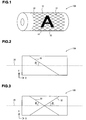
- the figures represent an example in which the member 10A with recessed portions is a gravure printing cylinder for gravure printing ( FIG. 1 ).
- the member 10A with recessed portions has on a surface 12 a printing area 16 in which a large number of recessed portions 14 (gravure cells in the case of a gravure printing cylinder) are formed and a non-printing area 18 in which the recessed portions 14 are not formed, that is, a smooth surface area without the recessed portions 14 ( FIG. 1 ).
- a viscous material 20 in the illustrated example
- the viscous material 20 accumulates in the recessed portions 14.
- a doctor blade 22 By causing a doctor blade 22 to horizontally stick up on the surface 12 and relatively moving the doctor blade 22 (in the example illustrated in FIG.
- the member 10A with recessed portions which is a gravure printing cylinder rotates), the excess viscous material 20 is scraped off the surface 12 of the member with recessed portions.
- the member 10A with recessed portions includes a base member 24A having on the surface 12 the printing area 16 in which the large number of recessed portions 14 are formed and the non-printing area 18 in which the recessed portions 14 are not formed, and a DLC coating 26 is formed so as to cover the printing area 16 and the non-printing area 18.
- a plurality of grinding traces 30 and 32 are formed, which form inclined angles of other than 0° and 90° with respect to an imaginary extension 28 of the doctor blade 22 which horizontally sticks up on the surface 12.
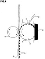
- reference symbols 48 and 50 denote an impression cylinder and a target of the printing such as paper or a plastic film, respectively.
- the imaginary extension 28 of the doctor blade 22 which horizontally sticks up on the surface 12 is a line in parallel with a direction of an X axis (width direction) when the X axis and a Y axis are taken as illustrated in FIG. 2 and FIG. 3 with respect to the plate surface of the member 10A with recessed portions. Therefore, the plurality of grinding traces 30 and 32 are formed, which form inclined angles of other than 0° and 90° with respect to a reference line in parallel with the direction of the X axis on the plate surface.
- the grinding traces 30 and 32 may form only one first angle ⁇ 1 corresponding to the inclined angle of other than 0° and 90° (30° in the examples illustrated in FIG. 2 and FIG. 3 ) with respect to the imaginary extension 28 of the doctor blade 22, but it is suitable that the grinding traces 30 and 32 also have a second angle ⁇ 2 corresponding to the inclined angle of other than 0° and 90° (30° in the examples illustrated in FIG. 2 and FIG. 3 ) with respect to the imaginary extension 28 of the doctor blade 22 and that the grinding trace 30 at the first angle ⁇ 1 and the grinding trace 32 at the second angle ⁇ 2 intersect each other.
- FIG. 1 illustrates an example in which such intersection is made.
- the member 10A with recessed portions by manufacturing the base member 24A, which has on the surface 12 the printing area 16 in which the large number of recessed portions 14 are formed and the non-printing area 18 in which the recessed portions 14 are not formed, forming the DLC coating 26 so as to cover the printing area 16 and the non-printing area 18, and grinding the DLC coating 26, the plurality of grinding traces 30 and 32 may be formed, which form inclined angles of other than 0° and 90° with respect to the imaginary extension 28 of the doctor blade 22 which horizontally sticks up on the surface.
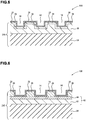
- the base member on which the DLC coating is provided may have, for example, a structure illustrated in FIG. 5 or FIG. 6 .
- the base member 24A is a base member including a cylindrical or flat plate-like base material 34 and a metal layer 36 (copper plating in the illustrated example) provided on the surface of the cylindrical or flat plate-like base material 34 (cylindrical aluminum roll in the illustrated example) and having the large number of recessed portions formed on the surface thereof.
- the metal layer 36 further has a nickel plating layer 38 provided thereon.
- the DLC coating 26 is formed on the nickel plating layer 38 to form the member 10A with recessed portions. Note that, in the illustrated example, a case in which the nickel plating layer 38 is formed as an underlying metal layer is exemplified, but chromium plating may also be used as the underlying metal layer.
- the base member 24A is manufactured by preparing the cylindrical or flat plate-like base material 34 (cylindrical aluminum roll in the illustrated example), providing the metal layer 36 (copper plating in the illustrated example) on the surface of the cylindrical or flat plate-like base material 34, applying a photosensitive material on the surface of the metal layer 36, carrying out exposure and development, and after that, forming by corrosion the large number of recessed portions on the surface of the metal layer 36, and applying nickel plating to form the nickel plating layer 38.
- the nickel plating layer 38 is formed as an underlying metal layer is exemplified, but chromium plating may also be used as the underlying metal layer.
- a base member 24B illustrated in FIG. 6 is a base member including the cylindrical or flat plate-like base material 34, a metal layer 40 (copper plating layer 42 and nickel plating layer 44 in the illustrated example) provided on the surface of the cylindrical or flat plate-like base material 34 (cylindrical aluminum roll in the illustrated example), and a patterning layer 46 formed by exposing and developing a photosensitive material provided on the metal layer 40.
- the DLC coating 26 is formed on the patterning layer 46 and the nickel plating layer 44 to form a member 10B with recessed portions.
- the recessed portions 14 are not formed by corrosion treatment, but are achieved by patterning of the photosensitive material provided on the metal layer 40.
- the base member 24B is manufactured by preparing the cylindrical or flat plate-like base material 34 (cylindrical aluminum roll in the illustrated example), providing the metal layer 40 (copper plating layer 42 and nickel plating layer 44 in the illustrated example) on the surface of the cylindrical or flat plate-like base material 34, applying the photosensitive material onto the metal layer 40, and carrying out exposure and development to form the patterning layer 46.
- the cylindrical or flat plate-like base material 34 may include a cushion layer formed of a rubber or a resin having a cushioning property.
- the base material may be formed on the cushion layer formed of a rubber or a resin having a cushioning property.
- a synthetic rubber such as silicone rubber or an elastic synthetic resin such as polyurethane or polystyrene can be used.
- the thickness of the cushion layer is not specifically limited. For example, a thickness of about 1 cm to 5 cm is sufficient.
- Examples of the base material including the cushion layer formed of a rubber or a resin having a cushioning property include the gravure plate described in Patent Document 2.
- the member 10A with recessed portions and the member 10B with recessed portions are gravure printing cylinders, but, in the case of a deep-etch offset plate, a flat plate-like base material may be used.
- the viscous material may be a functional material such as a functional ink.
- the viscous material is an adhesive or the like. In other words, any plate which uses a doctor blade falls within the member with recessed portions according to the present invention.
- a plate base material (aluminum hollow roll) having a circumference of 600 mm and a length of 1,100 mm was prepared.
- Boomerang Line an automatic laser gravure plate making roll manufacturing equipment manufactured by THINK LABORATORY Co., Ltd.
- the plate base material was placed in a copper plating bath, and the entire hollow roll was immersed in a plating solution to form a copper plating layer of 80 ⁇ m at 20 A/dm 2 and 6.0 V. No rashes and pits were formed on the plated surface, and a uniform copper plating layer was obtained.
- the surface of the copper plating layer was polished by a four-head polisher (a polisher manufactured by THINK LABORATORY Co., Ltd.) to cause the surface of the copper plating layer to be a uniform polished surface.
- a photosensitive film thermal resist: TSER2104 E4 (manufactured by THINK LABORATORY Co., Ltd.)
- the thickness of the obtained photosensitive film measured by a film thickness gauge (F20 manufactured by Fillmetrics, Inc. and marketed by Matsushita Techno Trading Co., Ltd.) was 4 ⁇ m.
- Cupric chloride liquid was used as corrosive liquid, and the corrosion was carried out by spraying at 35°C for 100 seconds. Further, the depth of the corrosion was 15 ⁇ m. Then, sodium hydroxide was used with the dilution ratio of 20 g/L at 40°C for 180 seconds to remove the resist. Then, the plate base material was placed in a nickel plating bath, and was halfway immersed in a plating solution to form a nickel plating layer of 2 ⁇ m at 2 A/dm 2 and 7.0 V. No rashes and pits were formed on the plated surface, and a uniform nickel plating layer was obtained.
- a DLC coating film was formed by CVD on the surfaces of the nickel plating layer and the resist pattern.
- An intermediate layer was formed to have a thickness of 0.1 ⁇ m in an atmosphere of argon/hydrogen gas using hexamethyldisiloxane as a material gas at a film formation temperature of 80 to 120°C for a film formation time period of 60 minutes.
- a DLC layer was formed to have a thickness of 2 ⁇ m using toluene as a material gas at a film formation temperature of 80 to 120°C for a film formation time period of 90 minutes.
- the surface of the cylinder member obtained in this way was reciprocatively ground by a sandpaper grinding machine using a sandpaper having a grit size of #2000 (manufactured by 3M Company) at an angle of 30° for 2 minutes to form the grinding traces having a first angle which is 30° clockwise with respect to the imaginary extension of the doctor blade as illustrated in FIG. 3 .
- grinding traces having a second angle which is 30° counterclockwise with respect to the imaginary extension of the doctor blade were formed so that the grinding traces at the first angle and the grinding traces at the second angle intersect each other.
- each of the grinding traces had the depth of 0.2 ⁇ m and the arithmetic mean roughness Sa of the surface in the non-printing area of 0.03.
- the member with recessed portions obtained in this way was used to carry out package printing by gravure printing. A beautiful package was obtained without causing fogging.
- a plate base material (aluminum hollow roll) having a circumference of 600 mm and a length of 1,100 mm was prepared.
- Boomerang Line an automatic laser gravure plate making roll manufacturing equipment manufactured by THINK LABORATORY Co., Ltd.
- the plate base material was placed in a copper plating bath, and the entire hollow roll was immersed in a plating solution to form a copper plating layer of 80 ⁇ m at 20 A/dm 2 and 6.0 V. No rashes and pits were formed on the plated surface, and a uniform copper plating layer was obtained.
- the surface of the copper plating layer was polished by a four-head polisher (a polisher manufactured by THINK LABORATORY Co., Ltd.) to cause the surface of the copper plating layer to be a uniform polished surface. Then, the plate base material was placed in a nickel plating bath, and was halfway immersed in a plating solution to form a nickel plating layer of 2 ⁇ m at 2 A/dm 2 and 7.0 V. No rashes and pits were formed on the plated surface, and a uniform nickel plating layer was obtained.
- a photosensitive film thermal resist: TSER-NS (manufactured by THINK LABORATORY Co., Ltd.)
- TSER-NS manufactured by THINK LABORATORY Co., Ltd.
- the thickness of the obtained photosensitive film measured by a film thickness gauge (F20 manufactured by Fillmetrics, Inc. and marketed by Matsushita Techno Trading Co., Ltd.) was 7 ⁇ m.
- laser exposure was carried out and the image was developed.
- Laser Stream FX was used and predetermined pattern exposure was carried out with the exposure condition of 300 mJ/cm 2 .
- a DLC coating film was formed by CVD on the surfaces of the nickel plating layer and the resist pattern.
- An intermediate layer was formed to have a thickness of 0.1 ⁇ m in an atmosphere of argon/hydrogen gas using hexamethyldisiloxane as a material gas at a film formation temperature of 80 to 120°C for a film formation time period of 60 minutes.
- a DLC layer was formed to have a thickness of 2 ⁇ m using toluene as a material gas at a film formation temperature of 80 to 120°C for a film formation time period of 90 minutes.
- the surface of the cylinder member obtained in this way was reciprocatively ground by a sandpaper grinding machine using a sandpaper having a grit size of #2000 (manufactured by 3M Company) at an angle of 30° for 2 minutes to form the grinding traces having a first angle which is 30° clockwise with respect to the imaginary extension of the doctor blade as illustrated in FIG. 3 .
- grinding traces having a second angle which is 30° counterclockwise with respect to the imaginary extension of the doctor blade were formed so that the grinding traces at the first angle and the grinding traces at the second angle intersect each other.
- each of the grinding traces had the depth of 0.2 ⁇ m and the arithmetic mean roughness Sa of the surface in the non-printing area of 0.03.
- the member with recessed portions obtained in this way was used to carry out electrode wiring pattern printing with ink containing silver paste by gravure printing. A beautiful electrode wiring pattern was obtained without causing fogging.
- 10A, 10B member with recessed portion, 12: surface, 14: recessed portion, 16: printing area, 18: non-printing area, 20: viscous material, 22: doctor blade, 24A, 24B: base member, 26: DLC coating, 28: imaginary extension, 30, 32: grinding trace, 34: cylindrical or flat plate-like base material, 36, 40: metal layer, 38: nickel plating layer, 42: copper plating layer, 44: nickel plating layer, 46: patterning layer, 48: impression cylinder, 50: target of printing.
Landscapes
- Engineering & Computer Science (AREA)
- Chemical & Material Sciences (AREA)
- Ceramic Engineering (AREA)
- Inorganic Chemistry (AREA)
- Mechanical Engineering (AREA)
- Printing Plates And Materials Therefor (AREA)
- Manufacture Or Reproduction Of Printing Formes (AREA)
- Photosensitive Polymer And Photoresist Processing (AREA)
Description
- The present invention relates to a member with recessed portions, which has a large number of minute recessed portions provided on a surface thereof by diamond like carbon (DLC), and a method of manufacturing the same.
- A gravure printing cylinder and a deep-etch offset plate are members with recessed portions, which have on the surface thereof a printing area in which a large number of minute recessed portions are formed and a non-printing area in which the recessed portions are not formed. With regard to a gravure printing cylinder, for example, as described in
Patent Document 1, a technology which uses diamond like carbon (DLC) as a hard coating for covering gravure cells is known. - On the other hand, as a member with recessed portions, which has on the surface thereof a printing area in which a large number of minute recessed portions are formed and a non-printing area in which the recessed portions are not formed, an application cylinder which can uniformly apply to a target an adhesive, in particular, an adhesive for dry lamination to be used for a material for packaging food, drink, a pharmaceutical drug, or the like is known.
- Further, as a member with recessed portions, which has on the surface thereof a printing area in which a large number of minute recessed portions are formed and a non-printing area in which the recessed portions are not formed, a gravure printing cylinder or the like is used in printing conductive paste such as functional ink including ink containing silver paste when an electronic component such as a circuit board, a ceramic electronic component, a front filter of a plasma display panel (PDP), or an electro-magnetic shielding and light transmitting window material is manufactured.
- These members with recessed portions such as a gravure printing roll, a deep-etch offset plate, and an application cylinder are used under a state in which a cutting edge of a doctor blade is horizontally held in contact with the surface thereof to scrape a viscous material such as excess ink or adhesive on the surface thereof.
- However, when DLC is used as a hard coating for covering the surface, the friction coefficient of DLC is low, and thus, there is a problem in that ink in the non-printing area cannot be scraped well by the doctor blade, and so-called fogging is caused.
-
- Patent Document 1:
JP 2007-130996 A - Patent Document 2:
JP 2009-093170 A -
JP 2003 080662 -
EP 1938970 A1 discloses a gravure printing roll capable of improving plate fogging, being provided with a surface-reinforcing coating layer completely free from toxicity and the possibility of pollution, and of being excellent in printing durability; and a method of producing the roll. The gravure printing roll includes a metal hollow roll, a copper-plated layer provided on the surface of the hollow roll and formed with multiple gravure cells on the surface thereof, a metal layer provided on the surface of the copper-plated layer, a metal carbide gradient layer of the metal provided on the surface of the metal layer, and a diamond-like carbon film covering the surface of the metal carbide gradient layer, in which a pit being smaller than the minimum gravure cell in the highlighted portion of the copper-plated layer and having a size not permitting ink transfer is arranged so that at least one pit exists in the one-pitch area of a screen line in a non-image area. -
JP2000010300 A -
WO2007135898 A1 discloses a fully automatic manufacturing system for a gravure engraving roll that can fully automate a technique comprising forming a diamond-like carbon (DLC) on a copper plating layer in a gravure cylinder for use of the diamond-like carbon as a surface reinforcing covering layer and can realize unmanned operation even during night time. The fully automatic manufacturing system comprises copper plating forming means for plating a hollow roll with copper, gravure cell forming means for forming a gravure cell in a hollow roll plated with copper, DLC cover forming means for forming a DLC film on the hollow roll with the gravure cell formed therein, first automatic transfer means for automatically transferring the hollow roll onto the copper plating forming means, automatic carrying means for automatically carrying the hollow roll plated with copper in the copper plating forming means to the gravure cell forming means, and second automatic transfer means for automatically transferring the hollow roll with the gravure cell formed therein in the gravure cell forming means onto the DLC cover forming means. -
JP2009093170 A -
JP3022986B -
JP2004249696 A -
JPH07256854 A - The present invention has been made in view of the above-mentioned problem of the conventional art, and an object of the present invention is to provide a member with recessed portions which solves the problem of fogging, and a method of manufacturing the same.
- In order to solve the above-mentioned problem, according to the present invention, there is provided a member with recessed portions, including: a printing area in which a large number of recessed portions are formed on a surface thereof; and a non-printing area in which the recessed portions are not formed on the surface thereof, the surface being brought into contact with a viscous material so that the viscous material accumulates in the recessed portions, the excess viscous material being scraped off the surface by causing a doctor blade to horizontally stick up on the surface and relatively moving the doctor blade, in which: the member with recessed portions further includes: a base member having the printing area in which the large number of recessed portions are formed on the surface and the non-printing area in which the recessed portions are not formed on the surface; and a DLC coating formed so as to cover the printing area and the non-printing area; and the surface is provided with a plurality of grinding traces, which are formed by grinding the DLC coating, and form an inclined angle of other than 0° and 90° with respect to an imaginary extension of the doctor blade which horizontally sticks up on the surface.
- DLC has low frictional resistance and high sliding performance, and thus, ink on the surface of the member with recessed portions without a pattern (without a cell), that is, ink in the non-printing area, cannot be scraped well, and the problem of fogging arises. By grinding the surface to be coarse to increase the frictional resistance, the problem of fogging can be solved.
- Moreover the plurality of grinding traces have a first angle corresponding to the inclined angle of other than 0° and 90° with respect to the imaginary extension of the doctor blade and a second angle corresponding to the inclined angle of other than 0° and 90° with respect to the imaginary extension of the doctor blade, and grinding traces at the first angle and grinding traces at the second angle intersect each other.
- It is preferred that a depth of the plurality of grinding traces be equal to or larger than 0.05 µm and smaller than 0.3 µm. Further, it is preferred that the grinding is sandpaper grinding, and it is preferred to carry out grinding with a grit size of, for example, #1000 to 3000.
- It is suitable that an arithmetic mean roughness Sa of the surface in the non-printing area of the member with recessed portions be 0.005 to 0.10 µm. In this case, the arithmetic mean roughness Sa is a three-dimensional extension of a two-dimensional arithmetic mean roughness Ra, and is the volume surrounded by the curved surface shape and a mean plane divided by the measured area. When the mean plane is an xy plane, the vertical direction is a z axis, and the measured curved surface shape is z=f(x,y), the arithmetic mean roughness Sa is defined as follows.

- In the
Numerical Equation 1, Lx is the measured length in an x direction and Ly is the measured length in a y direction. These are determined by noncontact surface profile measurement using laser light or an electron beam. - The inclined angle of the traces of the grinding with respect to the imaginary extension of the doctor blade which horizontally sticks up on the surface is preferably 10° to 80°, and more preferably 30° to 60°.
- It is suitable that the depth of the recessed portions be 1 µm to 50 µm, but the depth is more preferably 5 to 15 µm, and further preferably 5 to 10 µm. The reason is that the amount of ink, adhesive, a functional material, or the like supplied to the recessed portions may be small.
- As a first aspect of the base member, it is preferred that the base member include a cylindrical or flat plate-like base material, and a metal layer provided on a surface of the cylindrical or flat plate-like base material and having the large number of recessed portions formed on the surface thereof. According to the first aspect of the base member, it is suitable that the recessed portions be formed by corrosion treatment, and, as the base material, aluminum, iron, or a composite material such as a carbon fiber reinforced resin is preferred. Further, according to the first aspect of the base member, as the metal layer, copper and/or nickel are preferred. In particular, it is suitable to form the base member by applying copper plating onto the surface of the base material, applying a photosensitive material onto the copper plating, carrying out exposure and development, and after that, corroding the copper plating to form the recessed portions, and applying on the surface thereof an underlying metal plating layer such as nickel plating or chromium plating.
- As a second aspect of the base member, it is preferred that the base member include a cylindrical or flat plate-like base material, a metal layer provided on a surface of the cylindrical or flat plate-like base material, and a patterning layer formed by exposing and developing a photosensitive material provided on the metal layer. According to the second aspect of the base member, the recessed portions are not formed by corrosion treatment, but are achieved by patterning of the photosensitive material provided on the metal layer. As the base material, aluminum, iron, or a composite material such as a carbon fiber reinforced resin is preferred. Further, according to the second aspect of the base member, as the metal layer, copper and/or nickel are preferred. In particular, by applying copper plating onto the surface of the base material, applying nickel plating onto the copper plating, applying the photosensitive material onto the nickel plating, and carrying out exposure and development, the recessed portions are formed on the nickel plating.
- It is further preferred that the base material include a cushion layer formed of a rubber or a resin having a cushioning property. In other words, the base material may be formed on the cushion layer formed of a rubber or a resin having a cushioning property. As the cushion layer, a synthetic rubber such as silicone rubber or an elastic synthetic resin such as polyurethane or polystyrene can be used. As long as the cushion layer is thick enough to have the cushioning property, that is, resilience, the thickness of the cushion layer is not specifically limited. For example, a thickness of about 1 cm to 5 cm is sufficient. Examples of the base material including the cushion layer formed of a rubber or a resin having a cushioning property include the gravure plate described in Patent Document 2.
- It is preferred that a thickness of the DLC coating be 0.1 µm to several tens of micrometers. More specifically, the thickness is preferably 0.1 µm to 20 µm, and more preferably 0.1 µm to 5 µm. In forming the DLC coating, it is preferred to form the thin film by CVD or sputtering.
- It is preferred that the member with recessed portion be a gravure printing cylinder. The reason is that the problem of fogging is solved and the printability is improved to ease printing. The gravure printing cylinder as the member with recessed portions according to the present invention is suitably used for package printing, and in addition, is also suitably used for, for example, printing functional ink including ink containing silver paste in manufacturing an electronic component.
- It is preferred that the member with recessed portion be a deep-etch offset plate. The reason is that the problem of fogging is solved and the printability is improved to ease printing.
- It is suitable that the member with recessed portion be an application cylinder. The application cylinder is suitably used as, for example, an application cylinder for uniformly applying to a target an adhesive, in particular, an adhesive for dry lamination used for a material for packaging food, drink, a pharmaceutical drug, or the like.
- According to the present invention, there is provided a product manufactured by using the member with recessed portions.
- According to the present invention, there is provided a method of manufacturing member with recessed portions, the member with recessed portions including: a printing area in which a large number of recessed portions are formed on a surface thereof; and a non-printing area in which the recessed portions are not formed on the surface thereof, the surface being brought into contact with a viscous material so that the viscous material accumulates in the recessed portions, the excess viscous material being scraped off the surface by causing a doctor blade to horizontally stick up on the surface and relatively moving the doctor blade, in which: the method including the steps of: manufacturing a base member having the printing area in which the large number of recessed portions are formed on the surface and the non-printing area in which the recessed portions are not formed on the surface; forming a DLC coating so as to cover the printing area and the non-printing area; and forming a plurality of grinding traces by grinding the DLC coating, the plurality of grinding traces forming an inclined angle of other than 0° and 90° with respect to an imaginary extension of the doctor blade which horizontally sticks up on the surface, wherein the step of forming the plurality of grinding traces includes forming the plurality of grinding traces having a first angle corresponding to the inclined angle of other than 0° and 90° with respect to the imaginary extension of the doctor blade and a second angle corresponding to the inclined angle of other than 0° and 90° with respect to the imaginary extension of the doctor blade so that grinding traces at the first angle and grinding traces at the second angle intersect each other.
- It is preferred that a depth of the plurality of grinding traces be 0.05 µm to 0.3 µm. Further, it is preferred that the grinding be sandpaper grinding, and it is preferred to carry out grinding with a grit size of, for example, #1000 to 3000.
- It is preferred that an arithmetic mean roughness Sa of the surface in the non-printing area of the member with recessed portions be 0.005 to 0.10 µm.
- It is suitable that a depth of the recessed portions be 1 µm to 50 µm, but the depth is more preferably 5 to 15 µm, and further preferably 5 to 10 µm. The reason is that the amount of ink, adhesive, a functional material, or the like supplied to the recessed portions may be small.
- It is suitable that a first aspect of the manufacturing a base member include the steps of: preparing a cylindrical or flat plate-like base material; providing a metal layer on a surface of the cylindrical or flat plate-like base material; and forming by corrosion the large number of recessed portions on a surface of the metal layer. According to the first aspect of the manufacturing a base member, it is suitable that the recessed portions be formed by corrosion treatment, and as the base material, aluminum, iron, or a composite material such as a carbon fiber reinforced resin is preferred. Further, according to the first aspect of the manufacturing a base member, as the metal layer, copper and/or nickel is preferred. In particular, it is suitable to form the base member by applying copper plating onto the surface of the base material, applying a photosensitive material onto the copper plating, carrying out exposure and development, and after that, corroding the copper plating to form the recessed portions, and applying onto the surface thereof an underlying metal plating layer such as nickel plating or chromium plating.
- It is preferred that a second aspect of the manufacturing a base member include the steps of: preparing a cylindrical or flat plate-like base material; providing a metal layer on a surface of the cylindrical or flat plate-like base material; and forming a patterning layer by exposing and developing a photosensitive material provided on the metal layer. According to the second aspect of the manufacturing a base member, the recessed portions are not formed by corrosion treatment, but are achieved by patterning of the photosensitive material provided on the metal layer. As the base material, aluminum, iron, or a composite material such as a carbon fiber reinforced resin is preferred. Further, according to the second aspect of the manufacturing a base member, as the metal layer, copper and/or nickel is preferred. In particular, by applying copper plating onto the surface of the base material, applying nickel plating onto the copper plating, applying the photosensitive material onto the nickel plating, and carrying out exposure and development, the recessed portions are formed on the nickel plating.
- It is further preferred that the base material include a cushion layer formed of a rubber or a resin having a cushioning property. In other words, the base material may be formed on the cushion layer formed of a rubber or a resin having a cushioning property. As the cushion layer, a synthetic rubber such as silicone rubber or an elastic synthetic resin such as polyurethane or polystyrene can be used. As long as the cushion layer is thick enough to have the cushioning property, that is, resilience, the thickness of the cushion layer is not specifically limited. For example, a thickness of about 1 cm to 5 cm is sufficient. Examples of the base material including the cushion layer formed of a rubber or a resin having a cushioning property include the gravure plate described in Patent Document 2.
- It is preferred that the thickness of the DLC coating be 0.1 µm to several tens of micrometers. More specifically, the thickness is preferably 0.1 µm to 20 µm and more preferably 0.1 µm to 5 µm. In forming the DLC coating, it is preferred to form the thin film by CVD or sputtering.
- The present invention may produce a remarkable effect of providing the member with recessed portions which solves the problem of fogging, and the method of manufacturing the same.
-
-
FIG. 1 is a schematic diagram of an exemplary member with recessed portions according to the present invention. -
FIG. 2 is an explanatory diagram illustrating an exemplary grinding trace in the member with recessed portions. -
FIG. 3 is an explanatory diagram illustrating other exemplary grinding traces in the member with recessed portions. -
FIG. 4 is an explanatory diagram illustrating exemplary gravure printing. -
FIG. 5 is a sectional view of a member with recessed portions according to one embodiment of the present invention. -
FIG. 6 is a sectional view of a member with recessed portions according to another embodiment of the present invention. - Embodiments of the present invention are described below, but the embodiments are merely exemplary embodiments.
- In the figures,
reference symbol 10A denotes a member with recessed portions according to the present invention. The figures represent an example in which themember 10A with recessed portions is a gravure printing cylinder for gravure printing (FIG. 1 ). - Description is made with reference
FIG. 1 to FIG. 5 . Themember 10A with recessed portions has on a surface 12 aprinting area 16 in which a large number of recessed portions 14 (gravure cells in the case of a gravure printing cylinder) are formed and anon-printing area 18 in which the recessedportions 14 are not formed, that is, a smooth surface area without the recessed portions 14 (FIG. 1 ). By bringing thesurface 12 into contact with a viscous material 20 (ink in the illustrated example), theviscous material 20 accumulates in the recessedportions 14. By causing adoctor blade 22 to horizontally stick up on thesurface 12 and relatively moving the doctor blade 22 (in the example illustrated inFIG. 4 , themember 10A with recessed portions which is a gravure printing cylinder rotates), the excessviscous material 20 is scraped off thesurface 12 of the member with recessed portions. Themember 10A with recessed portions includes abase member 24A having on thesurface 12 theprinting area 16 in which the large number of recessedportions 14 are formed and thenon-printing area 18 in which the recessedportions 14 are not formed, and aDLC coating 26 is formed so as to cover theprinting area 16 and thenon-printing area 18. By grinding theDLC coating 26, a plurality of grindingtraces imaginary extension 28 of thedoctor blade 22 which horizontally sticks up on thesurface 12. - Note that, in
FIG. 4 ,reference symbols - The
imaginary extension 28 of thedoctor blade 22 which horizontally sticks up on thesurface 12 is a line in parallel with a direction of an X axis (width direction) when the X axis and a Y axis are taken as illustrated inFIG. 2 and FIG. 3 with respect to the plate surface of themember 10A with recessed portions. Therefore, the plurality of grindingtraces - As illustrated in
FIG. 2 and 3 , the grinding traces 30 and 32 may form only one first angle θ1 corresponding to the inclined angle of other than 0° and 90° (30° in the examples illustrated inFIG. 2 and FIG. 3 ) with respect to theimaginary extension 28 of thedoctor blade 22, but it is suitable that the grinding traces 30 and 32 also have a second angle θ2 corresponding to the inclined angle of other than 0° and 90° (30° in the examples illustrated inFIG. 2 and FIG. 3 ) with respect to theimaginary extension 28 of thedoctor blade 22 and that the grindingtrace 30 at the first angle θ1 and the grindingtrace 32 at the second angle θ2 intersect each other.FIG. 1 illustrates an example in which such intersection is made. - In manufacturing the
member 10A with recessed portions, by manufacturing thebase member 24A, which has on thesurface 12 theprinting area 16 in which the large number of recessedportions 14 are formed and thenon-printing area 18 in which the recessedportions 14 are not formed, forming theDLC coating 26 so as to cover theprinting area 16 and thenon-printing area 18, and grinding theDLC coating 26, the plurality of grindingtraces imaginary extension 28 of thedoctor blade 22 which horizontally sticks up on the surface. - Further, the base member on which the DLC coating is provided may have, for example, a structure illustrated in
FIG. 5 or FIG. 6 . - In
FIG. 5 , thebase member 24A is a base member including a cylindrical or flat plate-like base material 34 and a metal layer 36 (copper plating in the illustrated example) provided on the surface of the cylindrical or flat plate-like base material 34 (cylindrical aluminum roll in the illustrated example) and having the large number of recessed portions formed on the surface thereof. Themetal layer 36 further has anickel plating layer 38 provided thereon. TheDLC coating 26 is formed on thenickel plating layer 38 to form themember 10A with recessed portions. Note that, in the illustrated example, a case in which thenickel plating layer 38 is formed as an underlying metal layer is exemplified, but chromium plating may also be used as the underlying metal layer. - The
base member 24A is manufactured by preparing the cylindrical or flat plate-like base material 34 (cylindrical aluminum roll in the illustrated example), providing the metal layer 36 (copper plating in the illustrated example) on the surface of the cylindrical or flat plate-like base material 34, applying a photosensitive material on the surface of themetal layer 36, carrying out exposure and development, and after that, forming by corrosion the large number of recessed portions on the surface of themetal layer 36, and applying nickel plating to form thenickel plating layer 38. Note that, in the illustrated example, a case in which thenickel plating layer 38 is formed as an underlying metal layer is exemplified, but chromium plating may also be used as the underlying metal layer. - Further, a
base member 24B illustrated inFIG. 6 is a base member including the cylindrical or flat plate-like base material 34, a metal layer 40 (copper plating layer 42 andnickel plating layer 44 in the illustrated example) provided on the surface of the cylindrical or flat plate-like base material 34 (cylindrical aluminum roll in the illustrated example), and apatterning layer 46 formed by exposing and developing a photosensitive material provided on themetal layer 40. TheDLC coating 26 is formed on thepatterning layer 46 and thenickel plating layer 44 to form amember 10B with recessed portions. - In the
base member 24B, the recessedportions 14 are not formed by corrosion treatment, but are achieved by patterning of the photosensitive material provided on themetal layer 40. - The
base member 24B is manufactured by preparing the cylindrical or flat plate-like base material 34 (cylindrical aluminum roll in the illustrated example), providing the metal layer 40 (copper plating layer 42 andnickel plating layer 44 in the illustrated example) on the surface of the cylindrical or flat plate-like base material 34, applying the photosensitive material onto themetal layer 40, and carrying out exposure and development to form thepatterning layer 46. - Note that, in the
base member 24A andbase member 24B, the cylindrical or flat plate-like base material 34 may include a cushion layer formed of a rubber or a resin having a cushioning property. In other words, the base material may be formed on the cushion layer formed of a rubber or a resin having a cushioning property. As the cushion layer, a synthetic rubber such as silicone rubber or an elastic synthetic resin such as polyurethane or polystyrene can be used. As long as the cushion layer is a thick enough to have the cushioning property, that is, resilience, the thickness of the cushion layer is not specifically limited. For example, a thickness of about 1 cm to 5 cm is sufficient. Examples of the base material including the cushion layer formed of a rubber or a resin having a cushioning property include the gravure plate described in Patent Document 2. - Further, description is made above about cases in which the
member 10A with recessed portions and themember 10B with recessed portions are gravure printing cylinders, but, in the case of a deep-etch offset plate, a flat plate-like base material may be used. Further, the viscous material may be a functional material such as a functional ink. Further, in the case of an application cylinder, the viscous material is an adhesive or the like. In other words, any plate which uses a doctor blade falls within the member with recessed portions according to the present invention. - The present invention is described below more specifically by way of examples. It goes without saying that the examples are merely exemplary examples and may not be construed as restrictive.
- A plate base material (aluminum hollow roll) having a circumference of 600 mm and a length of 1,100 mm was prepared. Boomerang Line (an automatic laser gravure plate making roll manufacturing equipment manufactured by THINK LABORATORY Co., Ltd.) was used to carry out the steps up to formation of a copper plating layer and a nickel plating layer described below. First, the plate base material (aluminum hollow roll) was placed in a copper plating bath, and the entire hollow roll was immersed in a plating solution to form a copper plating layer of 80 µm at 20 A/dm2 and 6.0 V. No rashes and pits were formed on the plated surface, and a uniform copper plating layer was obtained. The surface of the copper plating layer was polished by a four-head polisher (a polisher manufactured by THINK LABORATORY Co., Ltd.) to cause the surface of the copper plating layer to be a uniform polished surface. Next, the above-mentioned formed copper plating layer was used as the base material, and a photosensitive film (thermal resist: TSER2104 E4 (manufactured by THINK LABORATORY Co., Ltd.)) was applied onto the surface thereof (by a fountain coater), and drying was carried out. The thickness of the obtained photosensitive film measured by a film thickness gauge (F20 manufactured by Fillmetrics, Inc. and marketed by Matsushita Techno Trading Co., Ltd.) was 4 µm. Then, laser exposure was carried out and the image was developed. With regard to the above-mentioned laser exposure, Laser Stream FX was used and predetermined pattern exposure was carried out with the exposure condition of 500 mJ/cm2. Further, with regard to the above-mentioned development, a TLD developer (a developer manufactured by THINK LABORATORY Co., Ltd.) was used with the developer dilution ratio of (undiluted solution: water=1:7) and the development was carried out at 24°C for 90 seconds to form a predetermined resist pattern. Next, the above-mentioned formed resist pattern was used as an etching mask to corrode the copper surface. Cupric chloride liquid was used as corrosive liquid, and the corrosion was carried out by spraying at 35°C for 100 seconds. Further, the depth of the corrosion was 15 µm. Then, sodium hydroxide was used with the dilution ratio of 20 g/L at 40°C for 180 seconds to remove the resist. Then, the plate base material was placed in a nickel plating bath, and was halfway immersed in a plating solution to form a nickel plating layer of 2 µm at 2 A/dm2 and 7.0 V. No rashes and pits were formed on the plated surface, and a uniform nickel plating layer was obtained.
- A DLC coating film was formed by CVD on the surfaces of the nickel plating layer and the resist pattern. An intermediate layer was formed to have a thickness of 0.1 µm in an atmosphere of argon/hydrogen gas using hexamethyldisiloxane as a material gas at a film formation temperature of 80 to 120°C for a film formation time period of 60 minutes. Then, a DLC layer was formed to have a thickness of 2 µm using toluene as a material gas at a film formation temperature of 80 to 120°C for a film formation time period of 90 minutes.
- The surface of the cylinder member obtained in this way was reciprocatively ground by a sandpaper grinding machine using a sandpaper having a grit size of #2000 (manufactured by 3M Company) at an angle of 30° for 2 minutes to form the grinding traces having a first angle which is 30° clockwise with respect to the imaginary extension of the doctor blade as illustrated in
FIG. 3 . Similarly, grinding traces having a second angle which is 30° counterclockwise with respect to the imaginary extension of the doctor blade were formed so that the grinding traces at the first angle and the grinding traces at the second angle intersect each other. When the grinding traces were observed under a light interference microscope, each of the grinding traces had the depth of 0.2 µm and the arithmetic mean roughness Sa of the surface in the non-printing area of 0.03. - The member with recessed portions obtained in this way was used to carry out package printing by gravure printing. A beautiful package was obtained without causing fogging.
- A plate base material (aluminum hollow roll) having a circumference of 600 mm and a length of 1,100 mm was prepared. Boomerang Line (an automatic laser gravure plate making roll manufacturing equipment manufactured by THINK LABORATORY Co., Ltd.) was used to carry out the steps up to formation of a copper plating layer and a nickel plating layer described below. First, the plate base material (aluminum hollow roll) was placed in a copper plating bath, and the entire hollow roll was immersed in a plating solution to form a copper plating layer of 80 µm at 20 A/dm2 and 6.0 V. No rashes and pits were formed on the plated surface, and a uniform copper plating layer was obtained. The surface of the copper plating layer was polished by a four-head polisher (a polisher manufactured by THINK LABORATORY Co., Ltd.) to cause the surface of the copper plating layer to be a uniform polished surface. Then, the plate base material was placed in a nickel plating bath, and was halfway immersed in a plating solution to form a nickel plating layer of 2 µm at 2 A/dm2 and 7.0 V. No rashes and pits were formed on the plated surface, and a uniform nickel plating layer was obtained. With use of the above-mentioned formed nickel plating layer as the base material, a photosensitive film (thermal resist: TSER-NS (manufactured by THINK LABORATORY Co., Ltd.)) was applied on the surface thereof (by a fountain coater), and drying was carried out. The thickness of the obtained photosensitive film measured by a film thickness gauge (F20 manufactured by Fillmetrics, Inc. and marketed by Matsushita Techno Trading Co., Ltd.) was 7 µm. Then, laser exposure was carried out and the image was developed. With regard to the above-mentioned laser exposure, Laser Stream FX was used and predetermined pattern exposure was carried out with the exposure condition of 300 mJ/cm2. Further, with regard to the above-mentioned development, a TLD developer (a developer manufactured by THINK LABORATORY Co., Ltd.) was used with the developer dilution ratio of (undiluted solution: water=1:7) and the development was carried out at 24°C for 90 seconds to form a predetermined resist pattern.
- A DLC coating film was formed by CVD on the surfaces of the nickel plating layer and the resist pattern. An intermediate layer was formed to have a thickness of 0.1 µm in an atmosphere of argon/hydrogen gas using hexamethyldisiloxane as a material gas at a film formation temperature of 80 to 120°C for a film formation time period of 60 minutes. Then, a DLC layer was formed to have a thickness of 2 µm using toluene as a material gas at a film formation temperature of 80 to 120°C for a film formation time period of 90 minutes.
- The surface of the cylinder member obtained in this way was reciprocatively ground by a sandpaper grinding machine using a sandpaper having a grit size of #2000 (manufactured by 3M Company) at an angle of 30° for 2 minutes to form the grinding traces having a first angle which is 30° clockwise with respect to the imaginary extension of the doctor blade as illustrated in
FIG. 3 . Similarly, grinding traces having a second angle which is 30° counterclockwise with respect to the imaginary extension of the doctor blade were formed so that the grinding traces at the first angle and the grinding traces at the second angle intersect each other. When the grinding traces were observed under a light interference microscope, each of the grinding traces had the depth of 0.2 µm and the arithmetic mean roughness Sa of the surface in the non-printing area of 0.03. - The member with recessed portions obtained in this way was used to carry out electrode wiring pattern printing with ink containing silver paste by gravure printing. A beautiful electrode wiring pattern was obtained without causing fogging.
- 10A, 10B: member with recessed portion, 12: surface, 14: recessed portion, 16: printing area, 18: non-printing area, 20: viscous material, 22: doctor blade, 24A, 24B: base member, 26: DLC coating, 28: imaginary extension, 30, 32: grinding trace, 34: cylindrical or flat plate-like base material, 36, 40: metal layer, 38: nickel plating layer, 42: copper plating layer, 44: nickel plating layer, 46: patterning layer, 48: impression cylinder, 50: target of printing.
Claims (9)
- A method of manufacturing a member with recessed portions, the member with recessed portions including:a printing area in which a large number of recessed portions are formed on a surface thereof; anda non-printing area in which the recessed portions are not formed on the surface thereof,the surface being brought into contact with a viscous material so that the viscous material accumulates in the recessed portions,the excess viscous material being scraped off the surface by causing a doctor blade to horizontally stick up on the surface and relatively moving the doctor blade, the method comprising the steps of:manufacturing a base member having the printing area in which the large number of recessed portions are formed on the surface and the non-printing area in which the recessed portions are not formed on the surface;forming a DLC coating so as to cover the printing area and the non-printing area; andforming a plurality of grinding traces by grinding the DLC coating, the plurality of grinding traces forming an inclined angle of other than 0° and 90° with respect to an imaginary extension of the doctor blade which horizontally sticks up on the surface, wherein the step of forming a plurality of grinding traces comprises forming the plurality of grinding traces having a first angle corresponding to the inclined angle of other than 0° and 90° with respect to the imaginary extension of the doctor blade and a second angle corresponding to the an inclined angle of other than 0° and 90° with respect to the imaginary extension of the doctor blade so that the grinding traces at the first angle and grinding traces at the second angle intersect each other.
- A method of manufacturing a member with recessed portions according to claim 1, wherein a depth of the plurality of grinding traces is 0.05 µm to 0.3 µm.
- A method of manufacturing a member with recessed portions according to claim 1 or 2 , wherein an arithmetic mean roughness Sa of the surface in the non-printing area of the member with recessed portions is 0.005 to 0.10 µm.
- A method of manufacturing a member with recessed portions according to any one of claims 1 to 3, wherein a depth of the recessed portions is 1 µm to 50 µm.
- A method of manufacturing a member with recessed portions according to any one of claims 1 to 4, wherein the step of manufacturing a base member comprises the steps of:preparing a cylindrical or flat plate-like base material;providing a metal layer on a surface of the cylindrical or flat plate-like base material; andforming by corrosion the large number of recessed portions on a surface of the metal layer.
- A method of manufacturing a member with recessed portions according to any one of claims 1 to 4, wherein the step of manufacturing a base member comprises the steps of:preparing a cylindrical or flat plate-like base material;providing a metal layer on a surface of the cylindrical or flat plate-like base material; andforming a patterning layer by exposing and developing a photosensitive material provided on the metal layer.
- A method of manufacturing a member with recessed portions according to claim 5 or 6, wherein the metal layer is made of copper or nickel.
- A method of manufacturing a member with recessed portions according to claim 5 or 6, wherein the base material comprises a cushion layer formed of a rubber or a resin having a cushioning property.
- A method of manufacturing a member with recessed portions according to any one of claims 1 to 8, wherein a thickness of the DLC coating is 0.1 µm to 20 µm.
Applications Claiming Priority (2)
| Application Number | Priority Date | Filing Date | Title |
|---|---|---|---|
| JP2011028634A JP5859212B2 (en) | 2011-02-14 | 2011-02-14 | Manufacturing method of member with recess |
| PCT/JP2012/053315 WO2012111637A1 (en) | 2011-02-14 | 2012-02-14 | Member with concave portion and method for manufacturing same |
Publications (3)
| Publication Number | Publication Date |
|---|---|
| EP2676800A1 EP2676800A1 (en) | 2013-12-25 |
| EP2676800A4 EP2676800A4 (en) | 2015-11-25 |
| EP2676800B1 true EP2676800B1 (en) | 2018-04-04 |
Family
ID=46672556
Family Applications (1)
| Application Number | Title | Priority Date | Filing Date |
|---|---|---|---|
| EP12747273.6A Active EP2676800B1 (en) | 2011-02-14 | 2012-02-14 | Member with concave portion and method for manufacturing same |
Country Status (8)
| Country | Link |
|---|---|
| US (1) | US9090052B2 (en) |
| EP (1) | EP2676800B1 (en) |
| JP (1) | JP5859212B2 (en) |
| KR (1) | KR101659771B1 (en) |
| CN (1) | CN103328226B (en) |
| ES (1) | ES2668829T3 (en) |
| RU (1) | RU2559127C2 (en) |
| WO (1) | WO2012111637A1 (en) |
Families Citing this family (6)
| Publication number | Priority date | Publication date | Assignee | Title |
|---|---|---|---|---|
| DE102011002229A1 (en) * | 2011-04-21 | 2012-10-25 | Fercon GmbH | Apparatus and method for the production of gravure and offset printing plates or for printing cylindrical substrates |
| JP6149813B2 (en) * | 2013-10-28 | 2017-06-21 | 株式会社村田製作所 | Gravure plate manufacturing method, gravure printing method, and electronic component manufacturing method |
| CN107206826B (en) * | 2015-02-06 | 2020-09-04 | 株式会社Uacj | Gravure printing roller |
| KR101763166B1 (en) * | 2016-09-22 | 2017-08-03 | 한국과학기술원 | The method of coating a thin film using rolling scheme and the apparatus for coating a thin film using the same |
| CN112808514B (en) * | 2020-12-30 | 2021-11-23 | 珠海冠宇电池股份有限公司 | Gravure roller, gravure coating machine and preparation method of electrode plate |
| CN114228313A (en) * | 2021-11-24 | 2022-03-25 | 张竟夫 | Printing machine roller |
Family Cites Families (20)
| Publication number | Priority date | Publication date | Assignee | Title |
|---|---|---|---|---|
| JPS5824154A (en) * | 1981-08-05 | 1983-02-14 | Fuji Xerox Co Ltd | Transmitting mechanism of rotating force of copying machine |
| JP2635046B2 (en) * | 1987-05-27 | 1997-07-30 | 株式会社 東京機械製作所 | Roller for inking unit of lithographic printing press and method for manufacturing roller for inking unit of lithographic printing press |
| US4862799A (en) * | 1987-11-13 | 1989-09-05 | Rockwell International Corporation | Copper coated anodized aluminum ink metering roller |
| JP3022986B2 (en) * | 1990-10-12 | 2000-03-21 | 大日本印刷株式会社 | Method of preventing printing failure in gravure printing and gravure printing plate |
| JPH07256854A (en) * | 1994-03-18 | 1995-10-09 | Toppan Printing Co Ltd | Flat intaglio requiring no dampening water and method for offset printing using the same |
| JP4117943B2 (en) * | 1998-06-18 | 2008-07-16 | 株式会社シンク・ラボラトリー | Method for producing a printing plate having cushioning properties |
| JP4834944B2 (en) * | 2001-09-13 | 2011-12-14 | 大日本印刷株式会社 | How to prevent printing defects in gravure printing |
| EP1445098A1 (en) * | 2003-02-04 | 2004-08-11 | Kba-Giori S.A. | Blanket cylinder for an intaglio printing machine |
| JP4364534B2 (en) * | 2003-02-19 | 2009-11-18 | ヒラノ技研工業株式会社 | Image forming method |
| CN100446993C (en) * | 2003-05-16 | 2008-12-31 | 富士胶片株式会社 | Method for manufacturing support body for lithographic plate and its support body |
| DE10341709B4 (en) * | 2003-10-08 | 2007-09-20 | Koenig & Bauer Aktiengesellschaft | printing unit |
| CN100451862C (en) * | 2004-12-24 | 2009-01-14 | 东海橡胶工业株式会社 | Developing roll |
| WO2007040141A1 (en) * | 2005-09-30 | 2007-04-12 | Think Laboratory Co., Ltd. | Photogravure engraving roll and production method thereof |
| JP2007130996A (en) | 2005-10-14 | 2007-05-31 | Think Laboratory Co Ltd | Gravure plate-making roll and its manufacturing method |
| CN1986213B (en) * | 2005-12-22 | 2010-12-08 | 鸿富锦精密工业(深圳)有限公司 | Antiwear magnetic coating and its making process |
| US20090301326A1 (en) * | 2005-12-30 | 2009-12-10 | Barr George A | Coated print roll and method therefor |
| WO2007135898A1 (en) * | 2006-05-24 | 2007-11-29 | Think Laboratory Co., Ltd. | Fully automatic manufacturing system for gravure engraving roll |
| JP5198998B2 (en) * | 2007-09-20 | 2013-05-15 | 株式会社シンク・ラボラトリー | Gravure plate having cushioning properties and manufacturing method thereof |
| CN102216487B (en) * | 2008-10-29 | 2014-07-02 | Ntn株式会社 | Hard multilayer film formed body and method for manufacturing same |
| JP5015991B2 (en) * | 2008-11-11 | 2012-09-05 | トーカロ株式会社 | Printing roll and method for producing the same |
-
2011
- 2011-02-14 JP JP2011028634A patent/JP5859212B2/en active Active
-
2012
- 2012-02-14 CN CN201280005813.9A patent/CN103328226B/en active Active
- 2012-02-14 WO PCT/JP2012/053315 patent/WO2012111637A1/en active Application Filing
- 2012-02-14 US US13/976,658 patent/US9090052B2/en active Active
- 2012-02-14 EP EP12747273.6A patent/EP2676800B1/en active Active
- 2012-02-14 KR KR1020137018002A patent/KR101659771B1/en active IP Right Grant
- 2012-02-14 ES ES12747273.6T patent/ES2668829T3/en active Active
- 2012-02-14 RU RU2013128281/12A patent/RU2559127C2/en not_active IP Right Cessation
Non-Patent Citations (1)
| Title |
|---|
| None * |
Also Published As
| Publication number | Publication date |
|---|---|
| EP2676800A4 (en) | 2015-11-25 |
| RU2013128281A (en) | 2015-03-27 |
| US9090052B2 (en) | 2015-07-28 |
| JP5859212B2 (en) | 2016-02-10 |
| KR20140032968A (en) | 2014-03-17 |
| ES2668829T3 (en) | 2018-05-22 |
| WO2012111637A1 (en) | 2012-08-23 |
| KR101659771B1 (en) | 2016-09-26 |
| CN103328226B (en) | 2016-06-08 |
| JP2012166431A (en) | 2012-09-06 |
| RU2559127C2 (en) | 2015-08-10 |
| EP2676800A1 (en) | 2013-12-25 |
| CN103328226A (en) | 2013-09-25 |
| US20130269554A1 (en) | 2013-10-17 |
Similar Documents
| Publication | Publication Date | Title |
|---|---|---|
| EP2676800B1 (en) | Member with concave portion and method for manufacturing same | |
| CA2019046C (en) | Method of printing fine patterns | |
| WO2007040140A1 (en) | Photogravure engraving roll with cushioning layer and production method therefor | |
| EP3527376B1 (en) | Pattern-free anilox inking system and method | |
| EP3284610B1 (en) | Gravure cylinder and manufacturing method thereof | |
| JP2007118593A (en) | Photogravure reproduction roll with cushion layer and its manufacturing method | |
| KR20110003084A (en) | The gravure plate for offset printing and the method of manufacturing the same | |
| GB2198085A (en) | Printing apparatus and process | |
| JP4117943B2 (en) | Method for producing a printing plate having cushioning properties | |
| US20230051478A1 (en) | Gravure printing plate | |
| JPH11309951A (en) | Gravure printing plate, and manufacture of gravure printing plate | |
| JPH11314470A (en) | Intaglio plate having cushion property | |
| JP3923655B2 (en) | Intaglio with cushioning properties | |
| JP2009078500A (en) | Letterpress printer and method for manufacturing high-polymer el element by using the same | |
| JPH11314471A (en) | Intaglio plate material having cushioning property and intaglio plate | |
| JPH0434551A (en) | Printing intaglio and production of this printing intaglo and printing method using this plate | |
| JPH04267151A (en) | Preparation of planographic printing plate | |
| JP2008155614A (en) | Relief printer | |
| EP0180419A2 (en) | Printing method and plate | |
| JPH11221974A (en) | Gravure printing plate | |
| JPH074993B2 (en) | Ink measuring roller | |
| WO2024106046A1 (en) | Gravure plate, manufacturing method therefor, and manufacturing method for gravure printed matter using same | |
| JPH11309950A (en) | Gravure printing plate, and manufacture of gravure printing plate | |
| JPS6223306B2 (en) | ||
| JP2010076208A (en) | Relief-printing equipment |
Legal Events
| Date | Code | Title | Description |
|---|---|---|---|
| PUAI | Public reference made under article 153(3) epc to a published international application that has entered the european phase |
Free format text: ORIGINAL CODE: 0009012 |
|
| 17P | Request for examination filed |
Effective date: 20130627 |
|
| AK | Designated contracting states |
Kind code of ref document: A1 Designated state(s): AL AT BE BG CH CY CZ DE DK EE ES FI FR GB GR HR HU IE IS IT LI LT LU LV MC MK MT NL NO PL PT RO RS SE SI SK SM TR |
|
| DAX | Request for extension of the european patent (deleted) | ||
| RA4 | Supplementary search report drawn up and despatched (corrected) |
Effective date: 20151027 |
|
| RIC1 | Information provided on ipc code assigned before grant |
Ipc: G03F 7/40 20060101ALI20151021BHEP Ipc: B41N 1/12 20060101ALI20151021BHEP Ipc: B41N 1/06 20060101AFI20151021BHEP Ipc: B41C 1/00 20060101ALI20151021BHEP Ipc: G03F 7/00 20060101ALI20151021BHEP Ipc: B41C 1/18 20060101ALI20151021BHEP Ipc: B41N 1/20 20060101ALI20151021BHEP |
|
| STAA | Information on the status of an ep patent application or granted ep patent |
Free format text: STATUS: EXAMINATION IS IN PROGRESS |
|
| 17Q | First examination report despatched |
Effective date: 20161027 |
|
| GRAP | Despatch of communication of intention to grant a patent |
Free format text: ORIGINAL CODE: EPIDOSNIGR1 |
|
| STAA | Information on the status of an ep patent application or granted ep patent |
Free format text: STATUS: GRANT OF PATENT IS INTENDED |
|
| GRAS | Grant fee paid |
Free format text: ORIGINAL CODE: EPIDOSNIGR3 |
|
| INTG | Intention to grant announced |
Effective date: 20180111 |
|
| GRAA | (expected) grant |
Free format text: ORIGINAL CODE: 0009210 |
|
| STAA | Information on the status of an ep patent application or granted ep patent |
Free format text: STATUS: THE PATENT HAS BEEN GRANTED |
|
| AK | Designated contracting states |
Kind code of ref document: B1 Designated state(s): AL AT BE BG CH CY CZ DE DK EE ES FI FR GB GR HR HU IE IS IT LI LT LU LV MC MK MT NL NO PL PT RO RS SE SI SK SM TR |
|
| REG | Reference to a national code |
Ref country code: GB Ref legal event code: FG4D |
|
| REG | Reference to a national code |
Ref country code: CH Ref legal event code: EP |
|
| REG | Reference to a national code |
Ref country code: AT Ref legal event code: REF Ref document number: 985181 Country of ref document: AT Kind code of ref document: T Effective date: 20180415 |
|
| REG | Reference to a national code |
Ref country code: DE Ref legal event code: R096 Ref document number: 602012044757 Country of ref document: DE |
|
| REG | Reference to a national code |
Ref country code: IE Ref legal event code: FG4D |
|
| REG | Reference to a national code |
Ref country code: ES Ref legal event code: FG2A Ref document number: 2668829 Country of ref document: ES Kind code of ref document: T3 Effective date: 20180522 |
|
| REG | Reference to a national code |
Ref country code: NL Ref legal event code: MP Effective date: 20180404 |
|
| REG | Reference to a national code |
Ref country code: LT Ref legal event code: MG4D |
|
| PG25 | Lapsed in a contracting state [announced via postgrant information from national office to epo] |
Ref country code: NL Free format text: LAPSE BECAUSE OF FAILURE TO SUBMIT A TRANSLATION OF THE DESCRIPTION OR TO PAY THE FEE WITHIN THE PRESCRIBED TIME-LIMIT Effective date: 20180404 |
|
| PG25 | Lapsed in a contracting state [announced via postgrant information from national office to epo] |
Ref country code: AL Free format text: LAPSE BECAUSE OF FAILURE TO SUBMIT A TRANSLATION OF THE DESCRIPTION OR TO PAY THE FEE WITHIN THE PRESCRIBED TIME-LIMIT Effective date: 20180404 Ref country code: SE Free format text: LAPSE BECAUSE OF FAILURE TO SUBMIT A TRANSLATION OF THE DESCRIPTION OR TO PAY THE FEE WITHIN THE PRESCRIBED TIME-LIMIT Effective date: 20180404 Ref country code: NO Free format text: LAPSE BECAUSE OF FAILURE TO SUBMIT A TRANSLATION OF THE DESCRIPTION OR TO PAY THE FEE WITHIN THE PRESCRIBED TIME-LIMIT Effective date: 20180704 Ref country code: PL Free format text: LAPSE BECAUSE OF FAILURE TO SUBMIT A TRANSLATION OF THE DESCRIPTION OR TO PAY THE FEE WITHIN THE PRESCRIBED TIME-LIMIT Effective date: 20180404 Ref country code: FI Free format text: LAPSE BECAUSE OF FAILURE TO SUBMIT A TRANSLATION OF THE DESCRIPTION OR TO PAY THE FEE WITHIN THE PRESCRIBED TIME-LIMIT Effective date: 20180404 Ref country code: BG Free format text: LAPSE BECAUSE OF FAILURE TO SUBMIT A TRANSLATION OF THE DESCRIPTION OR TO PAY THE FEE WITHIN THE PRESCRIBED TIME-LIMIT Effective date: 20180704 Ref country code: LT Free format text: LAPSE BECAUSE OF FAILURE TO SUBMIT A TRANSLATION OF THE DESCRIPTION OR TO PAY THE FEE WITHIN THE PRESCRIBED TIME-LIMIT Effective date: 20180404 |
|
| PG25 | Lapsed in a contracting state [announced via postgrant information from national office to epo] |
Ref country code: GR Free format text: LAPSE BECAUSE OF FAILURE TO SUBMIT A TRANSLATION OF THE DESCRIPTION OR TO PAY THE FEE WITHIN THE PRESCRIBED TIME-LIMIT Effective date: 20180705 Ref country code: RS Free format text: LAPSE BECAUSE OF FAILURE TO SUBMIT A TRANSLATION OF THE DESCRIPTION OR TO PAY THE FEE WITHIN THE PRESCRIBED TIME-LIMIT Effective date: 20180404 Ref country code: HR Free format text: LAPSE BECAUSE OF FAILURE TO SUBMIT A TRANSLATION OF THE DESCRIPTION OR TO PAY THE FEE WITHIN THE PRESCRIBED TIME-LIMIT Effective date: 20180404 Ref country code: LV Free format text: LAPSE BECAUSE OF FAILURE TO SUBMIT A TRANSLATION OF THE DESCRIPTION OR TO PAY THE FEE WITHIN THE PRESCRIBED TIME-LIMIT Effective date: 20180404 |
|
| REG | Reference to a national code |
Ref country code: AT Ref legal event code: MK05 Ref document number: 985181 Country of ref document: AT Kind code of ref document: T Effective date: 20180404 |
|
| PG25 | Lapsed in a contracting state [announced via postgrant information from national office to epo] |
Ref country code: PT Free format text: LAPSE BECAUSE OF FAILURE TO SUBMIT A TRANSLATION OF THE DESCRIPTION OR TO PAY THE FEE WITHIN THE PRESCRIBED TIME-LIMIT Effective date: 20180806 |
|
| REG | Reference to a national code |
Ref country code: DE Ref legal event code: R097 Ref document number: 602012044757 Country of ref document: DE |
|
| PG25 | Lapsed in a contracting state [announced via postgrant information from national office to epo] |
Ref country code: RO Free format text: LAPSE BECAUSE OF FAILURE TO SUBMIT A TRANSLATION OF THE DESCRIPTION OR TO PAY THE FEE WITHIN THE PRESCRIBED TIME-LIMIT Effective date: 20180404 Ref country code: CZ Free format text: LAPSE BECAUSE OF FAILURE TO SUBMIT A TRANSLATION OF THE DESCRIPTION OR TO PAY THE FEE WITHIN THE PRESCRIBED TIME-LIMIT Effective date: 20180404 Ref country code: SK Free format text: LAPSE BECAUSE OF FAILURE TO SUBMIT A TRANSLATION OF THE DESCRIPTION OR TO PAY THE FEE WITHIN THE PRESCRIBED TIME-LIMIT Effective date: 20180404 Ref country code: EE Free format text: LAPSE BECAUSE OF FAILURE TO SUBMIT A TRANSLATION OF THE DESCRIPTION OR TO PAY THE FEE WITHIN THE PRESCRIBED TIME-LIMIT Effective date: 20180404 Ref country code: DK Free format text: LAPSE BECAUSE OF FAILURE TO SUBMIT A TRANSLATION OF THE DESCRIPTION OR TO PAY THE FEE WITHIN THE PRESCRIBED TIME-LIMIT Effective date: 20180404 Ref country code: AT Free format text: LAPSE BECAUSE OF FAILURE TO SUBMIT A TRANSLATION OF THE DESCRIPTION OR TO PAY THE FEE WITHIN THE PRESCRIBED TIME-LIMIT Effective date: 20180404 |
|
| PLBE | No opposition filed within time limit |
Free format text: ORIGINAL CODE: 0009261 |
|
| STAA | Information on the status of an ep patent application or granted ep patent |
Free format text: STATUS: NO OPPOSITION FILED WITHIN TIME LIMIT |
|
| PG25 | Lapsed in a contracting state [announced via postgrant information from national office to epo] |
Ref country code: SM Free format text: LAPSE BECAUSE OF FAILURE TO SUBMIT A TRANSLATION OF THE DESCRIPTION OR TO PAY THE FEE WITHIN THE PRESCRIBED TIME-LIMIT Effective date: 20180404 |
|
| 26N | No opposition filed |
Effective date: 20190107 |
|
| PG25 | Lapsed in a contracting state [announced via postgrant information from national office to epo] |
Ref country code: SI Free format text: LAPSE BECAUSE OF FAILURE TO SUBMIT A TRANSLATION OF THE DESCRIPTION OR TO PAY THE FEE WITHIN THE PRESCRIBED TIME-LIMIT Effective date: 20180404 |
|
| PG25 | Lapsed in a contracting state [announced via postgrant information from national office to epo] |
Ref country code: LU Free format text: LAPSE BECAUSE OF NON-PAYMENT OF DUE FEES Effective date: 20190214 Ref country code: MC Free format text: LAPSE BECAUSE OF FAILURE TO SUBMIT A TRANSLATION OF THE DESCRIPTION OR TO PAY THE FEE WITHIN THE PRESCRIBED TIME-LIMIT Effective date: 20180404 |
|
| REG | Reference to a national code |
Ref country code: IE Ref legal event code: MM4A |
|
| PG25 | Lapsed in a contracting state [announced via postgrant information from national office to epo] |
Ref country code: IE Free format text: LAPSE BECAUSE OF NON-PAYMENT OF DUE FEES Effective date: 20190214 |
|
| PGFP | Annual fee paid to national office [announced via postgrant information from national office to epo] |
Ref country code: IT Payment date: 20200225 Year of fee payment: 9 |
|
| PGFP | Annual fee paid to national office [announced via postgrant information from national office to epo] |
Ref country code: BE Payment date: 20200219 Year of fee payment: 9 Ref country code: CH Payment date: 20200219 Year of fee payment: 9 |
|
| PG25 | Lapsed in a contracting state [announced via postgrant information from national office to epo] |
Ref country code: MT Free format text: LAPSE BECAUSE OF NON-PAYMENT OF DUE FEES Effective date: 20190214 |
|
| PGFP | Annual fee paid to national office [announced via postgrant information from national office to epo] |
Ref country code: TR Payment date: 20200213 Year of fee payment: 9 Ref country code: FR Payment date: 20200219 Year of fee payment: 9 |
|
| PG25 | Lapsed in a contracting state [announced via postgrant information from national office to epo] |
Ref country code: CY Free format text: LAPSE BECAUSE OF FAILURE TO SUBMIT A TRANSLATION OF THE DESCRIPTION OR TO PAY THE FEE WITHIN THE PRESCRIBED TIME-LIMIT Effective date: 20180404 |
|
| PG25 | Lapsed in a contracting state [announced via postgrant information from national office to epo] |
Ref country code: IS Free format text: LAPSE BECAUSE OF FAILURE TO SUBMIT A TRANSLATION OF THE DESCRIPTION OR TO PAY THE FEE WITHIN THE PRESCRIBED TIME-LIMIT Effective date: 20180804 |
|
| PG25 | Lapsed in a contracting state [announced via postgrant information from national office to epo] |
Ref country code: HU Free format text: LAPSE BECAUSE OF FAILURE TO SUBMIT A TRANSLATION OF THE DESCRIPTION OR TO PAY THE FEE WITHIN THE PRESCRIBED TIME-LIMIT; INVALID AB INITIO Effective date: 20120214 |
|
| REG | Reference to a national code |
Ref country code: BE Ref legal event code: MM Effective date: 20210228 |
|
| PG25 | Lapsed in a contracting state [announced via postgrant information from national office to epo] |
Ref country code: LI Free format text: LAPSE BECAUSE OF NON-PAYMENT OF DUE FEES Effective date: 20210228 Ref country code: CH Free format text: LAPSE BECAUSE OF NON-PAYMENT OF DUE FEES Effective date: 20210228 |
|
| PG25 | Lapsed in a contracting state [announced via postgrant information from national office to epo] |
Ref country code: FR Free format text: LAPSE BECAUSE OF NON-PAYMENT OF DUE FEES Effective date: 20210228 |
|
| PG25 | Lapsed in a contracting state [announced via postgrant information from national office to epo] |
Ref country code: IT Free format text: LAPSE BECAUSE OF NON-PAYMENT OF DUE FEES Effective date: 20210214 |
|
| PG25 | Lapsed in a contracting state [announced via postgrant information from national office to epo] |
Ref country code: MK Free format text: LAPSE BECAUSE OF FAILURE TO SUBMIT A TRANSLATION OF THE DESCRIPTION OR TO PAY THE FEE WITHIN THE PRESCRIBED TIME-LIMIT Effective date: 20180404 |
|
| PG25 | Lapsed in a contracting state [announced via postgrant information from national office to epo] |
Ref country code: BE Free format text: LAPSE BECAUSE OF NON-PAYMENT OF DUE FEES Effective date: 20210228 |
|
| PGFP | Annual fee paid to national office [announced via postgrant information from national office to epo] |
Ref country code: ES Payment date: 20240325 Year of fee payment: 13 |
|
| PGFP | Annual fee paid to national office [announced via postgrant information from national office to epo] |
Ref country code: DE Payment date: 20240219 Year of fee payment: 13 Ref country code: GB Payment date: 20240219 Year of fee payment: 13 |