EP2676749A1 - Cast slab surface temperature measuring device used in continuous casting machine - Google Patents
Cast slab surface temperature measuring device used in continuous casting machine Download PDFInfo
- Publication number
- EP2676749A1 EP2676749A1 EP12747597.8A EP12747597A EP2676749A1 EP 2676749 A1 EP2676749 A1 EP 2676749A1 EP 12747597 A EP12747597 A EP 12747597A EP 2676749 A1 EP2676749 A1 EP 2676749A1
- Authority
- EP
- European Patent Office
- Prior art keywords
- cast slab
- continuous casting
- casting machine
- thermometer
- measuring device
- Prior art date
- Legal status (The legal status is an assumption and is not a legal conclusion. Google has not performed a legal analysis and makes no representation as to the accuracy of the status listed.)
- Withdrawn
Links
Images



Classifications
-
- B—PERFORMING OPERATIONS; TRANSPORTING
- B22—CASTING; POWDER METALLURGY
- B22D—CASTING OF METALS; CASTING OF OTHER SUBSTANCES BY THE SAME PROCESSES OR DEVICES
- B22D11/00—Continuous casting of metals, i.e. casting in indefinite lengths
- B22D11/16—Controlling or regulating processes or operations
- B22D11/18—Controlling or regulating processes or operations for pouring
- B22D11/181—Controlling or regulating processes or operations for pouring responsive to molten metal level or slag level
- B22D11/182—Controlling or regulating processes or operations for pouring responsive to molten metal level or slag level by measuring temperature
-
- B—PERFORMING OPERATIONS; TRANSPORTING
- B22—CASTING; POWDER METALLURGY
- B22D—CASTING OF METALS; CASTING OF OTHER SUBSTANCES BY THE SAME PROCESSES OR DEVICES
- B22D11/00—Continuous casting of metals, i.e. casting in indefinite lengths
- B22D11/16—Controlling or regulating processes or operations
-
- B—PERFORMING OPERATIONS; TRANSPORTING
- B22—CASTING; POWDER METALLURGY
- B22D—CASTING OF METALS; CASTING OF OTHER SUBSTANCES BY THE SAME PROCESSES OR DEVICES
- B22D11/00—Continuous casting of metals, i.e. casting in indefinite lengths
- B22D11/16—Controlling or regulating processes or operations
- B22D11/20—Controlling or regulating processes or operations for removing cast stock
- B22D11/201—Controlling or regulating processes or operations for removing cast stock responsive to molten metal level or slag level
- B22D11/202—Controlling or regulating processes or operations for removing cast stock responsive to molten metal level or slag level by measuring temperature
-
- G—PHYSICS
- G01—MEASURING; TESTING
- G01J—MEASUREMENT OF INTENSITY, VELOCITY, SPECTRAL CONTENT, POLARISATION, PHASE OR PULSE CHARACTERISTICS OF INFRARED, VISIBLE OR ULTRAVIOLET LIGHT; COLORIMETRY; RADIATION PYROMETRY
- G01J5/00—Radiation pyrometry, e.g. infrared or optical thermometry
- G01J5/02—Constructional details
- G01J5/05—Means for preventing contamination of the components of the optical system; Means for preventing obstruction of the radiation path
Definitions
- the present invention relates to a temperature measuring device that measures the surface temperature of a cast slab in a secondary cooling zone of a continuous casting machine.
- a continuous casting machine which manufactures a cast slab, includes a mold and a secondary cooling zone that is disposed on the downstream side of the mold and cools a cast slab drawn from the mold while conveying the cast slab in the drawing direction (casting direction). Rollers and a plurality of cooling nozzles are provided in the secondary cooling zone. The rollers are disposed on the surface and back of the cast slab drawn from the mold, and convey (support) the cast slab while the cast slab is interposed between the rollers in a thickness direction. The plurality of cooling nozzles are disposed between the rollers adjacent to each other in a drawing direction, and cool the cast slab that is conveyed by the rollers.
- the rollers provided in the secondary cooling zone are formed by integrating a plurality of rollers with roller segments and a case where the roller segments are not be used.
- cooling is important for the progress of the solidification of a cast slab and the prevention of quality defects such as cracking of a cast slab, which are caused by supercooling, is also important. For this reason, it is important to measure the surface temperature of the cast slab.
- the measurement of the temperature of the surface of the cast slab is not merely simple sporadic measurement of temperature, and the steady measurement of temperature has started to be performed as a quality control index in recent years. Further, as manufacturing quality improves, the improvement of measurement accuracy and the measurement over the entire width direction have started to be required. When the measurement of the temperature of the surface of a cast slab is steadily performed, keeping measurement accuracy for a long time is essential in a temperature measuring device.
- the following invention is disclosed in order to solve the above-mentioned problem.
- Patent Document 1 discloses a method that temporarily stops the spraying of secondary cooling water to a temperature measurement range of the surface of the cast slab in order to suppress the effect of steam at the time of the measurement of the surface temperature of a cast slab and measures the surface temperature of the cast slab while the generation of steam by the secondary cooling water is suppressed.
- Patent Document 2 discloses a method that suppresses the effect of steam and the like at the time of the measurement of the surface temperature of a cast slab by surrounding a measurement portion with a hood and purging the air in the hood.
- the bulging is a phenomenon where a cast slab swells between the rollers adjacent to each other in the casting direction (an area where the cast slab is not supported) due to the static pressure of liquid metal in the cast slab when a cast slab is manufactured by a continuous casting machine. Further, from the disclosure of Patent document 1, it is apparent that the measurement of the temperature of the cast slab is performed in a place where there is an adverse effect of steam if the spraying of the secondary cooling water is not stopped. For this reason, when spraying is not stopped, condensation or the attachment of steam or dust to a thermometer occurs and adversely affects measurement accuracy.
- thermometer when a thermometer is disposed close to the continuous casting machine, there is a case where the continuous casting machine should be stopped at the time of the maintenance such as the cleaning of the thermometer or a case where it is difficult to perform the maintenance of the rollers or cooling nozzles (which includes the demounting of the rollers or cooling nozzles from the continuous casting machine).
- the thermometer is installed at a position above one side of the cast slab in the width direction and the measurement of the temperature of the surface of the cast slab is performed obliquely above the cast slab (a position different from a position above the surface of the cast slab).
- thermometer In order to accurately measure the temperature of a portion that also includes an edge, it is preferable that the thermometer be installed above the cast slab as described above.
- steam or dust which adversely affects measurement accuracy, is apt to be attached to the thermometer, it is necessary to suppress the attachment of steam or dust to the thermometer.
- it is not possible to accurately measure the surface temperature of a cast slab in a steady state for example, when the spraying of the secondary cooling water is stopped, and it is not possible to accurately measure the temperature of an edge, for example, when the measurement of the temperature of a cast slab is performed obliquely above the cast slab.
- a measurement portion is surrounded by the hood, it is possible to reduce the effect of steam.
- a cast slab surface temperature measuring device which keeps measurement accuracy for a long time and has excellent maintainability, is not yet provided.
- the invention has been made in consideration of the above-mentioned circumstances, and an object of the invention is to provide a cast slab surface temperature measuring device used in a continuous casting machine that can suppress or prevent an effect of steam and the like, which reduces the measurement accuracy of the surface temperature of a cast slab, and simplify a maintenance work of the continuous casting machine by improving the maintainability of the thermometer during continuous casting.
- the invention employs the following measures.
- the temperature measuring device used in a continuous casting machine includes a support member that is installed on the side of roller support parts; an arm member of which a proximal portion is mounted on the support member; and a radiation thermometer which is provided at a distal end portion of the arm member and of which a light receiving opening is disposed at a position corresponding to a height in the range of 1.0 to 4.5 m from the surface of the cast slab. It is possible to suppress or prevent an adverse effect of steam and the like in a range where the temperature of the cast slab can be measured, by controlling a distance between the surface of the cast slab and the light receiving opening in an appropriate range.
- the radiation thermometer is installed at an end of the arm member that is rotatably mounted, it is possible to move (retreat) the radiation thermometer by rotating the arm member about the support member at the time of the maintenance of, for example, the continuous casting machine (for example, the maintenance of the rollers or pipes of nozzles for secondary cooling water). Accordingly, the radiation thermometer does not obstruct maintenance. Further, since it is possible to move the radiation thermometer, it is possible to perform the maintenance such as the cleaning of the radiation thermometer without stopping the continuous casting machine.
- the arm member may include a plurality of short arms, and the short arms, which are adjacent to each other, may be foldably connected to each other by a connection part.
- a connection part for example, it is possible not only to rotate the entire arm member about the support member but also to fold the adjacent short arms when moving the radiation thermometer. Accordingly, for example,even though a structure obstructing the movement of the radiation thermometer is present around the continuous casting machine, it is possible to easily make the radiation thermometer retreat to the outside of the continuous casting machine from the inside of the continuous casting machine that is above the surface of the cast slab.
- the arm member or one or more of the plurality of short arms may be provided with a telescopic mechanism of which the length is adjustable.
- the number of alternative methods of making the radiation thermometer retreat to the outside of the continuous casting machine from the inside of the continuous casting machine and a method of changing a temperature measurement position on the surface of a cast slab are increased.
- the ease of work for making the radiation thermometer retreat and work for changing the position of the radiation thermometer is increased, and it is possible to perform work for making the radiation thermometer retreat and work for changing the position of the radiation thermometer that consider the surrounding (for example, structures) around the continuous casting machine.
- a cast slab surface temperature measuring device (hereinafter, also simply referred to as a temperature measuring device) 10 used in a continuous casting machine is a device that measures the surface temperature of a cast slab 13, which is drawn from a mold (not shown) in a secondary cooling zone 12 of a continuous casting machine 11 and conveyed by rollers (not shown), in the width direction of the cast slab.
- the continuous casting machine 11 in which the temperature measuring device 10 is installed is a vertical bending type or curved type continuous casting machine, but is not limited to this.
- the continuous casting machine 11 may be a vertical type continuous casting machine or the like. The continuous casting machine 11 will be described in detail below.
- Rollers and a plurality of cooling nozzles are provided in the secondary cooling zone 12.
- the rollers are disposed on the surface and back of the cast slab 13 drawn from the mold, and convey the cast slab 13 while the cast slab 13 is interposed between the rollers in a thickness direction.
- the plurality of cooling nozzles are disposed between the rollers adjacent to each other in a drawing direction (hereinafter, referred to as a casting direction), and cool the cast slab 13.
- the rollers provided in the secondary cooling zone 12 are integrally formed by roller segments (an example of roller support parts) 14 by which the plurality of rollers are rotatably supported, and the plurality of roller segments 14 are disposed at intervals in the casting direction of the cast slab 13.
- the maintenance of the rollers for example, a work for demounting the rollers from the continuous casting machine 11 or a work for mounting the rollers on the continuous casting machine 11 is performed for each of the roller segments 14.
- the rollers may have the configuration where the plurality of rollers is not formed integrally.
- the work for demounting the rollers from the continuous casting machine or the work for mounting the rollers on the continuous casting machine is individually performed for each roller support part on which one roller (also including a cooling nozzle) is mounted.
- the temperature measuring device 10 includes a support (an example of a support member) 15 that is installed on the side of the roller segments 14, an arm member 17 of which a proximal portion (rotating portion) 16 is rotatably mounted on the support 15, and a radiation thermometer (hereinafter, also simply referred to as a thermometer) 19 that is provided at a distal end portion (temperature measuring portion) 18 of the arm member 17.
- the support 15 is erected in a passage 20 that is formed on the side of the roller segments 14, that is, outside the continuous casting machine 11 (outside a continuous caster) in the casting direction of the cast slab 13.
- the support is used here, but the support member is not limited to the support as long as the thermometer 19 can be disposed at a position corresponding to a target height.
- the side of the roller segments 14 represents the side of the roller segments 14 (cast slab 13) when the cast slab 13 to be conveyed is seen in plan view. Accordingly, the installation position of the support 15 is not limited to the passage 20. That is, as long as the installation position of the support 15 is not disposed at the roller segments 14 (at the main body of the continuous casting machine 11), the installation position of the support 15 may be disposed at, for example, the frame or the like of the continuous casting machine 11.
- a distance between the support 15 and the roller segment 14 is not particularly limited as long as the thermometer 19 can be disposed and retreat by the rotation of the arm member 17 as described below.
- the arm member 17 is provided in a direction orthogonal to the support 15, and is made of, for example, a steel material.
- the middle portion of the arm member 17 in the longitudinal direction may be partially folded in plan view in the shape of one or two steps.
- a structure 21 for example, a column and the like
- the shape of the arm member is not limited to the above-mentioned shape, and may be, for example, an "L shape", a "V shape", or an arc shape in plan view according to the environment around the continuous casting machine 11.
- the mounting of the proximal portion 16 of the arm member 17 on the support 15 by, for example, providing a rotating shaft at the arm member and mounting the rotating shaft on the support so that the rotating shaft is rotatable, or providing a rotating shaft at the support and mounting the proximal portion of the arm member on the rotating shaft so that the proximal portion is rotatable.
- the arm member 17 is manually rotated relative to the support 15 by, for example, a worker.
- the arm member may be provided with driving measures and may be automatically rotated by a control unit.
- the arm member may be further provided with a telescopic mechanism of which the length is adjustable.
- the telescopic mechanism there are, for example, a slide type telescopic mechanism that has been well known in the past and freely reciprocates an arm member relative to a support in the longitudinal direction of the arm member, a bellows type telescopic mechanism that has been well known in the past and increases and reduces the length of an arm member, and the like.
- the telescopic mechanism is not limited to these.
- the rotation area (hereinafter, also referred to as a turning area) of the above-mentioned arm member 17 becomes a position to which the cast slab 13 is horizontally conveyed and is in a plane parallel to the surface of the cast slab 13.
- the installation position of the temperature measuring device 10 is disposed on the upstream side of the secondary cooling zone 12 (the installation position of the temperature measuring device 10 is close to the mold)
- the cast slab is conveyed while being curved.
- the rotation area of the arm member 17 is in a plane that obliquely crosses the surface of the cast slab 13.
- the rotation area of the arm member is not limited to this as long as the arm member can move.
- the rotation area of the arm member may be in a plane that is orthogonal to the surface of the cast slab. Specifically, when the rotation center of the rotating shaft, which is provided at the arm member or the support, is disposed parallel to the casting direction, it is possible to rotate the arm member in a direction where the arm member is separated from or approaches the surface of the cast slab.
- thermometer 19 that has been well known in the past and detects heat radiation energy, which radiated from a high-temperature object, in a non-contact manner may be used as the radiation thermometer 19.
- the light receiving opening of the radiation thermometer 19 is disposed at a position that corresponds to the height in the range of 1.0 to 4.5 m from the surface of the cast slab 13. If the height of the position of the light receiving opening is smaller than 1.0 m from the surface of the cast slab, it is not possible to secure the distance that is required for the diffusion of steam generated by secondary cooling water. As a result, condensation or the attachment of steam or dust to the thermometer occurs, so that measurement accuracy is reduced.
- the height of the position of the light receiving opening is set to 1.0 m or more from the surface of the cast slab 13.
- an upper end of the roller segment reaches the position corresponding to a height smaller than 1 m from the surface of the cast slab.
- the thermometer comes into contact with the roller segment.
- the thermometer cannot be moved to a measurement position.
- the height of the light receiving opening from the surface of the cast slab 13 is preferably 1.3 m or more and more preferably 1.5 m or more.
- a gap between the adjacent roller segments that is, a gap that is used to measure the temperature of the cast slab is very small, for example, in the range of 30 to 200 mm.
- the fixing angle of the thermometer slightly deviates and the temperature of the roller is measured rather than the temperature of the cast slab, so that it is not possible to accurately measure the temperature of the surface of the cast slab. Therefore, the height of the position of the light receiving opening is set to 4.5 m or less from the surface of the cast slab 13. Even when the roller segments are not used, the gap is substantially the same as described above.
- the height of the position of the light receiving opening exceeds 3.5 m from the surface of the cast slab, operability deteriorates when the thermometer is rotated. Accordingly, it is preferable that the height of the position of the light receiving opening be set to 3.5 m or less from the surface of the cast slab. Further, considering the ease of cleaning of the thermometer or the maintainability of the thermometer, it is more preferable that the height of the position of the light receiving opening be set to 3.0 m or less from the surface of the cast slab. It is possible to adjust the height of the position of the light receiving opening from the surface of the cast slab 13 by changing the height (length) of the support 15. However, for example, lifting measures may be provided at the support and it may be possible to adjust the height of the position of the light receiving opening from the surface of the cast slab by changing the height of the support.
- the installation position of the thermometer 19 is not particularly limited. However, it is preferable that the installation position of the thermometer 19 be in the vicinity of the middle portion of the cast slab 13 in the width direction of the cast slab, that is, a position above the area within 300 mm from the substantially middle position of the cast slab.
- the width of the measurement visual field of the radiation thermometer is also changed between when measurement is performed from above and when measurement is performed obliquely above.
- the width of a cast slab, which can be casted by a general continuous casting machine generally exceeds 1 m.
- thermometer 19 may reciprocate in the longitudinal direction of the arm member.
- the temperature measuring device may be provided with measures for performing air purge toward the light receiving opening of the thermometer (for example, wind speed is in the range of 2 to 10 m/s). Thereby, it is possible to reduce errors during temperature measurement, so that it is possible to improve the accuracy of temperature measurement.
- measures for performing air purge toward the light receiving opening of the thermometer for example, wind speed is in the range of 2 to 10 m/s.
- FIGS. 1A and 1B A method of measuring the surface temperature of the cast slab 13 using the cast slab surface temperature measuring device 10, which is used in the continuous casting machine according to the embodiment of the invention, will be described with reference to FIGS. 1A and 1B .
- the arm member 17 is rotated about the support 15 (clockwise in FIG. 1A ) before the start of continuous casting so that the position of the thermometer 19 becomes a position above an area between the adjacent roller segments 14 in the vicinity of the middle portion of the cast slab 13 in the width direction of the cast slab.
- the height of the support 15 is adjusted so that the light receiving opening of the thermometer 19 is disposed at a position corresponding to a height in the range of 1.0 to 4.5 m from the surface of the cast slab 13 to be conveyed in the casting direction.
- the thermometer is disposed as described above, it is possible to measure the surface temperature of the cast slab 13 in the width direction of the cast slab in the secondary cooling zone 12 while the cast slab 13 drawn from the mold is conveyed in the casting direction.
- the surface temperature of the cast slab may be measured at part of the cast slab in the width direction or at the entire cast slab in the width direction (over the width of the entire cast slab) in accordance with the purpose.
- thermometer 19 By setting the light receiving opening of the thermometer 19 to the position corresponding to the above-mentioned height, it is possible to sufficiently increase the distance between the surface of the cast slab 13 and the light receiving opening up to a position where an adverse effect of steam and the like can be suppressed or prevented, within a range where the temperature of the cast slab 13 can be measured. Since the thermometer 19 is separated from the surface of the cast slab by 1 m or more, the attachment of steam or dust to the light receiving opening is suppressed. However, when the thermometer 19 is used for a long time or when the thermometer 19 is out of order, the cleaning and maintenance of the thermometer 19 need to be performed. In this case, as shown in FIG.
- the arm member 17 is rotated about the support 15 in the direction opposite to the above-mentioned disposition (counterclockwise in FIG. 1B ) so that the thermometer 19 is moved to the distal end portion of the continuous casting machine 11 in the width direction of the continuous casting machine, that is, a position where the maintenance of the thermometer 19 can be performed. Accordingly, it is not necessary to stop the continuous casting machine 11 whenever the maintenance of the thermometer 19 is performed, and it is possible to always perform the maintenance of the thermometer 19.
- the maintenance of the continuous casting machine 11 (for example, the maintenance of the rollers or pipes of nozzles for cooling water) also needs to be performed.
- the thermometer 19 is disposed above the surface of the cast slab 13 as shown in FIG. 1A , there is a case where the thermometer 19 obstructs the maintenance of the continuous casting machine 11 as it is and makes the maintenance difficult. Accordingly, the arm member 17 is rotated about the support 15 as shown in FIG 1B so that the thermometer 19 is moved. Therefore, the maintenance work of the continuous casting machine 11 is simplified.
- thermometer 19 After the maintenance of the thermometer 19 or the continuous casting machine 11 is finished, the thermometer 19 is disposed again at the position above an area between the adjacent roller segments 14 in the vicinity of the middle portion of the cast slab 13 in the width direction of the cast slab and measures the surface temperature of the cast slab 13 in the procedure opposite to the above-mentioned procedure.
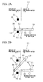
- a cast slab surface temperature measuring device (hereinafter, also simply referred to as a temperature measuring device) 30 used in a continuous casting machine according to a first modification will be described with reference to FIGS. 2A to 2C .
- the same members as the members of the above-mentioned temperature measuring device 10 are denoted by the same reference signs and the detailed description thereof will be omitted.
- An arm member 31 of the temperature measuring device 30 includes a plurality of short arms 32 and 33 (two here but may be three or more).
- the proximal-side short arm 32 and the end-side short arm 33, which are adjacent to each other, are foldably connected to each other by a connection part 34. For example, the folding of the adjacent short arms 32 and 33 is manually performed by a worker.
- the arm member may be provided with driving measures and may be automatically folded by a control unit. It is possible to make the shape of the arm member 31 be not only a linear shape (an "I” shape) but also an "L shape", a “V shape”, or the like in plan view by folding the arm member.
- the length of the arm member 31, which has a linear shape is substantially the same as the sum of a distance between the rotation center of the support 15 and the side surface of the cast slab and 1.1 m.
- the above-mentioned arm member 17 of the temperature measuring device 10 shown in FIGS. 1A and 1B is not provided with the connection part that makes the arm member foldable.
- the arm member 17 collides with the structure 21 and cannot retreat when a space is very small since various devices are provided around the continuous casting machine 11. Since the arm member 31 includes the plurality of short arms 32 and 33 and these short arms are adapted to be foldable as described above, the thermometer 19 can retreat to the outside of the continuous casting machine 11 where the maintenance of the thermometer 19 is easy, even though a space is small.
- thermometer 19 Before the retreat of the thermometer 19, that is, in FIG 2A , the thermometer 19 is disposed at the position above an area between the adjacent roller segments 14 in the vicinity of the middle portion of the cast slab 13 in the width direction of the cast slab and measures the surface temperature of the cast slab in the width direction.
- the arm member 31 has a linear shape at this time, but may be folded in an "L shape", a "V shape", or the like according to the temperature measurement position.
- the thermometer 19 is made to retreat, first, the arm member 31 is rotated about the support 15 in a direction where the thermometer 19 is moved to the outside of the continuous casting machine 11 as shown in FIG. 2B (counterclockwise in FIG. 2B ). At this time, the arm member 31 is rotated to a position where the connection part 34, which connects the short arm 32 with the short arm 33, is positioned outside the continuous casting machine 11 in plan view.
- the end-side short arm 33 is rotated about the connection part 34 in a direction where the thermometer 19 is moved to the outside of the continuous casting machine 11 as shown in FIG. 2C (counterclockwise in FIG. 2C ) so that the arm member 31 is folded in a "V shape" in plan view.
- the short arm 33 is rotated to a position where the thermometer 19 and the end-side short arm 33 are positioned outside the continuous casting machine 11 in plan view.
- the support 15 and the arm member 31 of the temperature measuring device 30 form the retreat measures of the thermometer 19.
- thermometer 19 By the above-mentioned configuration, it is possible to make the thermometer 19 reliably retreat to the outside of the continuous casting machine 11 while preventing the arm member 31 (or the thermometer 19) from colliding with the structure 21. For this reason, the maintainability of the thermometer 19 is further improved as compared to a case where the thermometer retreats to the distal end portion of the cast slab in the width direction. Moreover, since it is possible to make the thermometer 19 retreat to the outside of the continuous casting machine 11, the maintenance, such as mounting and demounting, of the rollers of the continuous casting machine 11 or facilities related with secondary cooling is easy. In addition, in the cases of some contents of the maintenance, the thermometer may retreat to the distal end portion of the cast slab in the width direction without retreating to the outside of a continuous caster.
- the arm member 31 Since the arm member 31 is adapted to be foldable as described above, it is possible to dispose the thermometer 19 at the position of the destination above an area between the adjacent roller segments 14 in the vicinity of the middle portion of the cast slab 13 in the width direction of the cast slab by changing, for example, the radius of rotation of the arm member 31 even though the thermometer 19 is moved to the upstream side or the downstream side in the casting direction. That is, the support 15 and the arm member 31 of the temperature measuring device 30 form not only the above-mentioned retreat measures of the thermometer 19 but also position changing measures. Accordingly, even though the casting speed is changed, it is possible to measure the surface temperature of the cast slab at a position where behind an outlet of the mold and the cooling time of the cast slab is constant. For this reason, the cast slab surface temperature measuring device 30 used in the continuous casting machine according to the first modification is useful for the improvement of the quality of a cast slab.
- a cast slab surface temperature measuring device (hereinafter, also simply referred to as a temperature measuring device) 40 used in a continuous casting machine according to a second modification will be described with reference to FIGS. 3A to 3D .
- the same members as the members of the above-mentioned temperature measuring device 10 are denoted by the same reference signs and the detailed description thereof will be omitted.
- An arm member 41 of the temperature measuring device 40 includes a plurality of short arms 42 and 43 (two here but may be three or more).
- the proximal-side short arm 42 and the end-side short arm 43, which are adjacent to each other, are foldably connected to each other by a connection part 44.
- the end-side short arm 43 of the two short arms 42 and 43 is provided with a telescopic mechanism 45 of which the length is adjustable. Only the proximal-side short arm may be provided with a telescopic mechanism, and both (two, or more) short arms may be provided with telescopic mechanisms.
- the telescopic mechanism 45 is formed of a slide type telescopic mechanism that has been well known in the past and makes the end-side short arm 43 freely reciprocate relative to the distal end portion of the proximal-side short arm 42 in the longitudinal direction of the end-side short arm. Specifically, the connection part 44 mounted on the distal end portion of the proximal-side short arm 42 moves in a long hole (long groove) 46 that is formed in the longitudinal direction of the end-side short arm 43.
- the telescopic mechanism may be formed of the above-mentioned bellows type telescopic mechanism that has been well known in the past, but is not limited these. For example, the movement of the end-side short arm 43 is manually performed by a worker.
- the short arm may be provided with driving measures and may be automatically moved by a control unit.
- the folding of the proximal-side short arm 42 and the end-side short arm 43, which are adjacent to each other, is manually performed by a worker.
- the arm member may be provided with driving measures and may be automatically folded by a control unit.
- thermometer 19 Before the retreat of the thermometer 19, that is, in FIG. 3A , the thermometer 19 is disposed at the position above an area between the adjacent roller segments 14 in the vicinity of the middle portion of the cast slab 13 in the width direction of the cast slab and measures the surface temperature of the cast slab in the width direction.
- the arm member 41 has a linear shape at this time, but may have an "L shape", a "V shape", or the like.
- the thermometer 19 is made to retreat, first, the arm member 41 is rotated about the support 15 in a direction where the connection part 44 is moved to the outside of the continuous casting machine 11 as shown in FIG 3B (counterclockwise in FIG. 3B ).
- the arm member 41 is rotated to a position where the connection part 44, which connects the short arm 42 with the short arm 43, is positioned outside the continuous casting machine 11 in plan view.
- the end-side short arm 43 is rotated relative to the proximal-side short arm 42 (clockwise in FIG. 3B ) so that the end-side short arm 43 is orthogonal to the casting direction of the cast slab.
- the end-side short arm 43 is made to slide relative to the distal end portion of the proximal-side short arm 42 in a direction where the thermometer 19 and the end-side short arm 43 are moved to the outside of the continuous casting machine 11 from the inside of the continuous casting machine 11 in plan view (to the left side in FIG. 3C ).
- the short arm 43 is moved to a position where the end-side short arm 43 is positioned outside the continuous casting machine 11 in plan view.
- the proximal-side short arm 42 is rotated about the support 15 in a direction where the thermometer 19 is separated from the inside of the continuous casting machine 11 (counterclockwise in FIG. 3D ).
- the short arm 42 is rotated to a position where the thermometer 19 is positioned outside the continuous casting machine 11 in plan view.
- the support 15 and the arm member 41 of the temperature measuring device 40 form the retreat measures of the thermometer 19 and position changing measures.
- thermometer retreat it is possible to make the thermometer retreat to the outside of the continuous casting machine 11 by the above-mentioned temperature measuring device 10 or temperature measuring device 30.
- the telescopic mechanism 45 is provided like in the temperature measuring device 40, the number of alternatives (methods or procedures of moving the arm member to retreat) of the retreat measures of the thermometer 19 is increased. Accordingly, it is possible to perform a work for retreat according to the surrounding environment.
- the cast slab surface temperature measuring device which is used in the continuous casting machine according to this embodiment, is used as described above, it is possible to suppress or prevent an effect of steam and the like, which reduces the measurement accuracy of the surface temperature of a cast slab, and to simplify the maintenance work of the continuous casting machine by improving the maintainability of the thermometer during continuous casting.
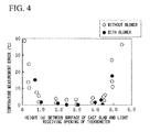
- the temperature measuring device 10 having the configuration shown in FIGS. 1A and 1B was used, the position corresponding to the height of a light receiving opening (light receiving opening of the thermometer) of a radiation thermometer relative to the surface of a cast slab was changed to various positions, and a temperature measurement error (error) was examined. Measurement was performed after about one month has passed after the cleaning of the light receiving opening, and was performed about thirty times for two years. The results thereof are shown in FIG. 4 .
- the temperature measurement error shown in FIG 4 was obtained from "(a batch measured value obtained by a thermocouple)-(a measured value obtained by a radiation thermometer)" by the comparison of a batch measured value obtained by a thermocouple and a measured value obtained by a radiation thermometer.
- the results are shown by the results when air is blown at a wind speed of 2 to 10 m/s below the light receiving opening (with blower/ ⁇ mark) and the results when air is not blown below the light receiving opening (without blower/ ⁇ mark).
- thermometer When a height (distance) between the surface of a cast slab and the light receiving opening of the thermometer was in the range of 1.0 to 4.5 m, regardless of whether air was blown, the error was smaller than 10°C as apparent from FIG. 4 and sufficiently practical use was allowed. When the height was smaller than 1.0 m, foreign materials were attached to the light receiving opening after a thermometer was used for a few weeks and an error of 10°C or more appeared on the results of the temperature measurement. On the other hand, when the height exceeded 4.5 m (5.0 m in FIG 4 ), the thermometer fixed by the support and the arm member was affected by a low-temperature structure such as rollers disposed around a measurement place and there was a case where a large error appeared on the results of the temperature measurement.
- the invention has been described above with reference to the embodiment. However, the invention is not limited to any configuration described in the embodiment, and also includes other embodiments and modifications that are devised within the scope of the fact described in claims.
- a case where the slab surface temperature measuring device used in the continuous casting machine of the invention is formed by the combination of all or a part of the above-mentioned respective embodiment and modifications is also included in the range of the right of the invention.
- a case where the cast slab surface temperature measuring device is installed on one side of the roller support parts in the width direction has been described in the above-mentioned embodiment.
- the cast slab surface temperature measuring device may be installed on both sides of the roller support parts in the width direction (the same position or different positions in the drawing direction of a cast slab).
- the cast slab surface temperature measuring devices may be installed at a plurality of positions in the drawing direction of a cast slab, and the cast slab surface temperature measuring devices may be disposed alternately (in a zigzag pattern) at a plurality of positions on both sides of the roller support parts in the width direction over the drawing direction of a cast slab.
- the cast slab surface temperature measuring device of the invention it is possible to suppress or prevent an effect of steam and the like, which reduces the measurement accuracy of the surface temperature of a cast slab, and to simplify the maintenance work of the continuous casting machine by improving the maintainability of the thermometer during continuous casting.
Landscapes
- Engineering & Computer Science (AREA)
- Mechanical Engineering (AREA)
- Physics & Mathematics (AREA)
- General Physics & Mathematics (AREA)
- Spectroscopy & Molecular Physics (AREA)
- Continuous Casting (AREA)
- Radiation Pyrometers (AREA)
Abstract
Description
- The present invention relates to a temperature measuring device that measures the surface temperature of a cast slab in a secondary cooling zone of a continuous casting machine. Priority is claimed on Japanese Patent Application No.
2011-029006, filed February 14, 2011 - A continuous casting machine, which manufactures a cast slab, includes a mold and a secondary cooling zone that is disposed on the downstream side of the mold and cools a cast slab drawn from the mold while conveying the cast slab in the drawing direction (casting direction). Rollers and a plurality of cooling nozzles are provided in the secondary cooling zone. The rollers are disposed on the surface and back of the cast slab drawn from the mold, and convey (support) the cast slab while the cast slab is interposed between the rollers in a thickness direction. The plurality of cooling nozzles are disposed between the rollers adjacent to each other in a drawing direction, and cool the cast slab that is conveyed by the rollers. There is a case where the rollers provided in the secondary cooling zone are formed by integrating a plurality of rollers with roller segments and a case where the roller segments are not be used.
In the above-mentioned secondary cooling zone, cooling is important for the progress of the solidification of a cast slab and the prevention of quality defects such as cracking of a cast slab, which are caused by supercooling, is also important. For this reason, it is important to measure the surface temperature of the cast slab. - The measurement of the temperature of the surface of the cast slab is not merely simple sporadic measurement of temperature, and the steady measurement of temperature has started to be performed as a quality control index in recent years. Further, as manufacturing quality improves, the improvement of measurement accuracy and the measurement over the entire width direction have started to be required.
When the measurement of the temperature of the surface of a cast slab is steadily performed, keeping measurement accuracy for a long time is essential in a temperature measuring device. The following invention is disclosed in order to solve the above-mentioned problem.
Patent Document 1 discloses a method that temporarily stops the spraying of secondary cooling water to a temperature measurement range of the surface of the cast slab in order to suppress the effect of steam at the time of the measurement of the surface temperature of a cast slab and measures the surface temperature of the cast slab while the generation of steam by the secondary cooling water is suppressed. Patent Document 2 discloses a method that suppresses the effect of steam and the like at the time of the measurement of the surface temperature of a cast slab by surrounding a measurement portion with a hood and purging the air in the hood. -
- [Patent Document 1] Japanese Unexamined Patent Application, First Publication No.
2009-195959 - [Patent Document 2] Japanese Unexamined Patent Application, First Publication No.
S55-133858 - However, the methods in the related art have the following problems still to be solved.
Though tentatively, since the spraying of the secondary cooling water is stopped in the method disclosed in Patent Document 1, the surface temperature of the cast slab rises due to heat recuperation. For this reason, it is not possible to accurately measure the surface temperature of the cast slab in a steady state. In addition, since heat recuperation occurs on the cast slab, there is a concern about the deterioration of the internal quality of the cast slab that is caused by the bulging between the rollers adjacent to each other in the casting direction of the cast slab. The bulging is a phenomenon where a cast slab swells between the rollers adjacent to each other in the casting direction (an area where the cast slab is not supported) due to the static pressure of liquid metal in the cast slab when a cast slab is manufactured by a continuous casting machine.
Further, from the disclosure of Patent document 1, it is apparent that the measurement of the temperature of the cast slab is performed in a place where there is an adverse effect of steam if the spraying of the secondary cooling water is not stopped. For this reason, when spraying is not stopped, condensation or the attachment of steam or dust to a thermometer occurs and adversely affects measurement accuracy. - Furthermore, when a thermometer is disposed close to the continuous casting machine, there is a case where the continuous casting machine should be stopped at the time of the maintenance such as the cleaning of the thermometer or a case where it is difficult to perform the maintenance of the rollers or cooling nozzles (which includes the demounting of the rollers or cooling nozzles from the continuous casting machine).
In addition, in Patent Document 1, the thermometer is installed at a position above one side of the cast slab in the width direction and the measurement of the temperature of the surface of the cast slab is performed obliquely above the cast slab (a position different from a position above the surface of the cast slab). Accordingly, it is difficult to discriminate an edge portion of the cast slab, which is positioned on the side opposite to the installation position of the thermometer, from the surrounding environment. Therefore, it is not possible to accurately define the width of the cast slab, so that it is not possible to specify the position of the edge portion of the cast slab. For this reason, it is difficult to measure the temperature of an edge portion, so that it is not possible to accurately measure temperature. - It is necessary to install the hood at a position close to the cast slab in the method disclosed in Patent Document 2. For this reason, it is necessary to structurally integrate the thermometer with the roller segments. Accordingly, when the thermometer is out of order during the operation of the continuous casting machine, it is not possible to demount the thermometer from the roller segments. For this reason, it is not possible to perform the maintenance of the thermometer.
Further, it is necessary to install devices, which purge the air toward the hood or the cast slab, on the roller segments. For this reason, for example, whenever the roller segments are replaced, it is necessary to perform work for demounting and mounting the devices, so that the production loss of a cast slab caused by the extension of time for replacement is generated. In addition, when the hood installed at a portion of a cast slab of which the temperature is to be measured is separated from a fixing portion from whatever cause, the hood and the cast slab come into contact with each other, which may cause the generation of scratches on the cast slab. - In order to accurately measure the temperature of a portion that also includes an edge, it is preferable that the thermometer be installed above the cast slab as described above. However, since steam or dust, which adversely affects measurement accuracy, is apt to be attached to the thermometer, it is necessary to suppress the attachment of steam or dust to the thermometer. However, in the related art, it is not possible to accurately measure the surface temperature of a cast slab in a steady state, for example, when the spraying of the secondary cooling water is stopped, and it is not possible to accurately measure the temperature of an edge, for example, when the measurement of the temperature of a cast slab is performed obliquely above the cast slab. Further, for example, when a measurement portion is surrounded by the hood, it is possible to reduce the effect of steam. However, there is a problem in that it is difficult to perform maintenance.
That is, a cast slab surface temperature measuring device, which keeps measurement accuracy for a long time and has excellent maintainability, is not yet provided. - The invention has been made in consideration of the above-mentioned circumstances, and an object of the invention is to provide a cast slab surface temperature measuring device used in a continuous casting machine that can suppress or prevent an effect of steam and the like, which reduces the measurement accuracy of the surface temperature of a cast slab, and simplify a maintenance work of the continuous casting machine by improving the maintainability of the thermometer during continuous casting. Solution to Problem
- In order to achieve the object by solving the above-mentioned problems, the invention employs the following measures.
- (1) That is, a temperature measuring device used in a continuous casting machine according to an aspect of the invention measures the surface temperature of a part or all of a cast slab in a width direction of the cast slab, which is drawn from a mold and conveyed by rollers, in a secondary cooling zone of the continuous casting machine. The temperature measuring device includes a support member that is installed on the side of roller support parts by which the rollers are rotatably supported; an arm member of which a proximal portion is rotatably mounted on the support member; and a radiation thermometer which is provided at a distal end portion of the arm member and of which a light receiving opening can be disposed at a position corresponding to a height in the range of 1.0 to 4.5 m from the surface of the cast slab.
-
- (2) In the cast slab surface temperature measuring device used in a continuous casting machine according to (1), the arm member may include a plurality of short arms and the short arms, which are adjacent to each other, may be foldably connected to each other by a connection part.
-
- (3) In the cast slab surface temperature measuring device used in a continuous casting machine according to (2), at least one of the short arms may include a telescopic mechanism of which the length is adjustable.
-
- (4) In the cast slab surface temperature measuring device used in a continuous casting machine according to (1), the arm member may include a telescopic mechanism of which the length is adjustable.
- The temperature measuring device used in a continuous casting machine according to the aspect of the invention includes a support member that is installed on the side of roller support parts; an arm member of which a proximal portion is mounted on the support member; and a radiation thermometer which is provided at a distal end portion of the arm member and of which a light receiving opening is disposed at a position corresponding to a height in the range of 1.0 to 4.5 m from the surface of the cast slab.
It is possible to suppress or prevent an adverse effect of steam and the like in a range where the temperature of the cast slab can be measured, by controlling a distance between the surface of the cast slab and the light receiving opening in an appropriate range.
In addition, since the radiation thermometer is installed at an end of the arm member that is rotatably mounted, it is possible to move (retreat) the radiation thermometer by rotating the arm member about the support member at the time of the maintenance of, for example, the continuous casting machine (for example, the maintenance of the rollers or pipes of nozzles for secondary cooling water). Accordingly, the radiation thermometer does not obstruct maintenance. Further, since it is possible to move the radiation thermometer, it is possible to perform the maintenance such as the cleaning of the radiation thermometer without stopping the continuous casting machine.
That is, when the above-mentioned aspect is employed, it is possible to suppress or prevent the effect of steam and the like, which reduces the measurement accuracy of the surface temperature of a cast slab, and to simplify the maintenance work of the continuous casting machine by improving the maintainability of the thermometer during continuous casting. - The arm member may include a plurality of short arms, and the short arms, which are adjacent to each other, may be foldably connected to each other by a connection part. In this case, for example, it is possible not only to rotate the entire arm member about the support member but also to fold the adjacent short arms when moving the radiation thermometer. Accordingly, for example,even though a structure obstructing the movement of the radiation thermometer is present around the continuous casting machine, it is possible to easily make the radiation thermometer retreat to the outside of the continuous casting machine from the inside of the continuous casting machine that is above the surface of the cast slab.
In the above-mentioned configuration, if a folding angle or the like between adjacent short arms is changed, it is possible to also measure the surface temperature of the cast slab in the vicinity of the middle portion of the cast slab in the width direction of the cast slab, for example, at a different position in the drawing (casting) direction of the cast slab. As a result, even though the casting speed is changed, it is possible to measure the surface temperature of the cast slab at a position where behind an outlet of the mold and the cooling time of the cast slab is constatant. Therefore, it is also possible to contribute to the improvement of casting quality.
Since the measurement of the temperature of a cast slab is to be performed at substantially the same position in a fixed point observation manner in order to control quality, the movement of the radiation thermometer with each arm member for maintenance has not been considered in the past. - The arm member or one or more of the plurality of short arms may be provided with a telescopic mechanism of which the length is adjustable. In this case, the number of alternative methods of making the radiation thermometer retreat to the outside of the continuous casting machine from the inside of the continuous casting machine and a method of changing a temperature measurement position on the surface of a cast slab are increased. As a result, the ease of work for making the radiation thermometer retreat and work for changing the position of the radiation thermometer is increased, and it is possible to perform work for making the radiation thermometer retreat and work for changing the position of the radiation thermometer that consider the surrounding (for example, structures) around the continuous casting machine.
-
-
FIG. 1A is a view illustrating a state where a cast slab surface temperature measuring device used in a continuous casting machine according to an embodiment of the invention measures temperature. -
FIG. 1B is a view illustrating the retreat state of the cast slab surface temperature measuring device used in the continuous casting machine according to the embodiment of the invention. -
FIG. 2A is a view illustrating a state where a cast slab surface temperature measuring device used in a continuous casting machine according to a first modification measures temperature. -
FIG. 2B is a view illustrating a state of the cast slab surface temperature measuring device used in the continuous casting machine according to the first modification in the middle of retreat. -
FIG. 2C is a view illustrating the retreat state of the cast slab surface temperature measuring device used in the continuous casting machine according to the first modification. -
FIG. 3A is a view illustrating a state where a cast slab surface temperature measuring device used in a continuous casting machine according to a second modification is used. -
FIG. 3B is a view illustrating a state of the cast slab surface temperature measuring device used in the continuous casting machine according to the second modification in the middle of retreat. -
FIG. 3C is a view illustrating a state of the cast slab surface temperature measuring device used in the continuous casting machine according to the second modification in the middle of retreat. -
FIG. 3D is a view illustrating the retreat state of the cast slab surface temperature measuring device used in the continuous casting machine according to the second modification. -
FIG. 4 is a graph showing a relationship between a height to a light receiving opening of a thermometer from the surface of a cast slab and a temperature measurement error of the surface of the cast slab. - Embodiments of the invention will be described with reference to the attached drawings.
As shown inFIGS. 1A and 1B , a cast slab surface temperature measuring device (hereinafter, also simply referred to as a temperature measuring device) 10 used in a continuous casting machine according to an embodiment of the invention is a device that measures the surface temperature of acast slab 13, which is drawn from a mold (not shown) in asecondary cooling zone 12 of acontinuous casting machine 11 and conveyed by rollers (not shown), in the width direction of the cast slab. Thecontinuous casting machine 11 in which thetemperature measuring device 10 is installed is a vertical bending type or curved type continuous casting machine, but is not limited to this. For example, thecontinuous casting machine 11 may be a vertical type continuous casting machine or the like. Thecontinuous casting machine 11 will be described in detail below. - Rollers and a plurality of cooling nozzles are provided in the
secondary cooling zone 12. The rollers are disposed on the surface and back of thecast slab 13 drawn from the mold, and convey thecast slab 13 while thecast slab 13 is interposed between the rollers in a thickness direction. The plurality of cooling nozzles are disposed between the rollers adjacent to each other in a drawing direction (hereinafter, referred to as a casting direction), and cool thecast slab 13. The rollers provided in thesecondary cooling zone 12 are integrally formed by roller segments (an example of roller support parts) 14 by which the plurality of rollers are rotatably supported, and the plurality ofroller segments 14 are disposed at intervals in the casting direction of thecast slab 13. The maintenance of the rollers, for example, a work for demounting the rollers from thecontinuous casting machine 11 or a work for mounting the rollers on thecontinuous casting machine 11 is performed for each of theroller segments 14.
The rollers may have the configuration where the plurality of rollers is not formed integrally. In this case, the work for demounting the rollers from the continuous casting machine or the work for mounting the rollers on the continuous casting machine is individually performed for each roller support part on which one roller (also including a cooling nozzle) is mounted. - The
temperature measuring device 10 includes a support (an example of a support member) 15 that is installed on the side of theroller segments 14, anarm member 17 of which a proximal portion (rotating portion) 16 is rotatably mounted on thesupport 15, and a radiation thermometer (hereinafter, also simply referred to as a thermometer) 19 that is provided at a distal end portion (temperature measuring portion) 18 of thearm member 17.
Thesupport 15 is erected in apassage 20 that is formed on the side of theroller segments 14, that is, outside the continuous casting machine 11 (outside a continuous caster) in the casting direction of thecast slab 13. The support is used here, but the support member is not limited to the support as long as thethermometer 19 can be disposed at a position corresponding to a target height.
The side of theroller segments 14 represents the side of the roller segments 14 (cast slab 13) when thecast slab 13 to be conveyed is seen in plan view. Accordingly, the installation position of thesupport 15 is not limited to thepassage 20. That is, as long as the installation position of thesupport 15 is not disposed at the roller segments 14 (at the main body of the continuous casting machine 11), the installation position of thesupport 15 may be disposed at, for example, the frame or the like of thecontinuous casting machine 11. A distance between thesupport 15 and theroller segment 14 is not particularly limited as long as thethermometer 19 can be disposed and retreat by the rotation of thearm member 17 as described below. - The
arm member 17 is provided in a direction orthogonal to thesupport 15, and is made of, for example, a steel material. The middle portion of thearm member 17 in the longitudinal direction may be partially folded in plan view in the shape of one or two steps. By setting the shape of thearm member 17, it is possible to reduce the restriction of the movement of thearm member 17, which is caused by the environment around thecontinuous casting machine 11, for example, a structure 21 (for example, a column and the like) such as a crane that is used to replace the segments when thearm member 17 is rotated (turned) about thesupport 15.
The shape of the arm member is not limited to the above-mentioned shape, and may be, for example, an "L shape", a "V shape", or an arc shape in plan view according to the environment around thecontinuous casting machine 11. - It is possible to perform the mounting of the
proximal portion 16 of thearm member 17 on thesupport 15 by, for example, providing a rotating shaft at the arm member and mounting the rotating shaft on the support so that the rotating shaft is rotatable, or providing a rotating shaft at the support and mounting the proximal portion of the arm member on the rotating shaft so that the proximal portion is rotatable.
Thearm member 17 is manually rotated relative to thesupport 15 by, for example, a worker. However, the arm member may be provided with driving measures and may be automatically rotated by a control unit.
The arm member may be further provided with a telescopic mechanism of which the length is adjustable.
As the telescopic mechanism, there are, for example, a slide type telescopic mechanism that has been well known in the past and freely reciprocates an arm member relative to a support in the longitudinal direction of the arm member, a bellows type telescopic mechanism that has been well known in the past and increases and reduces the length of an arm member, and the like. However, the telescopic mechanism is not limited to these. - If the installation position of the
temperature measuring device 10 is disposed on the downstream side of thesecondary cooling zone 12, the rotation area (hereinafter, also referred to as a turning area) of the above-mentionedarm member 17 becomes a position to which thecast slab 13 is horizontally conveyed and is in a plane parallel to the surface of thecast slab 13. In addition, if the installation position of thetemperature measuring device 10 is disposed on the upstream side of the secondary cooling zone 12 (the installation position of thetemperature measuring device 10 is close to the mold), the cast slab is conveyed while being curved. Accordingly, the rotation area of thearm member 17 is in a plane that obliquely crosses the surface of thecast slab 13.
The rotation area of the arm member is not limited to this as long as the arm member can move. For example, the rotation area of the arm member may be in a plane that is orthogonal to the surface of the cast slab. Specifically, when the rotation center of the rotating shaft, which is provided at the arm member or the support, is disposed parallel to the casting direction, it is possible to rotate the arm member in a direction where the arm member is separated from or approaches the surface of the cast slab. - For example, a thermometer that has been well known in the past and detects heat radiation energy, which radiated from a high-temperature object, in a non-contact manner may be used as the
radiation thermometer 19.
The light receiving opening of theradiation thermometer 19 is disposed at a position that corresponds to the height in the range of 1.0 to 4.5 m from the surface of thecast slab 13.
If the height of the position of the light receiving opening is smaller than 1.0 m from the surface of the cast slab, it is not possible to secure the distance that is required for the diffusion of steam generated by secondary cooling water. As a result, condensation or the attachment of steam or dust to the thermometer occurs, so that measurement accuracy is reduced. For this reason, the height of the position of the light receiving opening is set to 1.0 m or more from the surface of thecast slab 13. However, there is a case where an upper end of the roller segment reaches the position corresponding to a height smaller than 1 m from the surface of the cast slab. In this case, when the thermometer is turned, the thermometer comes into contact with the roller segment. For this reason, the thermometer cannot be moved to a measurement position. In order to reliably avoid this contact, the height of the light receiving opening from the surface of thecast slab 13 is preferably 1.3 m or more and more preferably 1.5 m or more. - In addition, a gap between the adjacent roller segments, that is, a gap that is used to measure the temperature of the cast slab is very small, for example, in the range of 30 to 200 mm. For this reason, when the height of the position of the light receiving opening exceeds 4.5 m from the surface of the cast slab, the fixing angle of the thermometer slightly deviates and the temperature of the roller is measured rather than the temperature of the cast slab, so that it is not possible to accurately measure the temperature of the surface of the cast slab. Therefore, the height of the position of the light receiving opening is set to 4.5 m or less from the surface of the
cast slab 13. Even when the roller segments are not used, the gap is substantially the same as described above. However, if the height of the position of the light receiving opening exceeds 3.5 m from the surface of the cast slab, operability deteriorates when the thermometer is rotated. Accordingly, it is preferable that the height of the position of the light receiving opening be set to 3.5 m or less from the surface of the cast slab. Further, considering the ease of cleaning of the thermometer or the maintainability of the thermometer, it is more preferable that the height of the position of the light receiving opening be set to 3.0 m or less from the surface of the cast slab.
It is possible to adjust the height of the position of the light receiving opening from the surface of thecast slab 13 by changing the height (length) of thesupport 15. However, for example, lifting measures may be provided at the support and it may be possible to adjust the height of the position of the light receiving opening from the surface of the cast slab by changing the height of the support. - As long as the installation position of the
thermometer 19 is above the surface of thecast slab 13, that is, a position overlapping thecast slab 13 in plan view, the installation position of thethermometer 19 is not particularly limited. However, it is preferable that the installation position of thethermometer 19 be in the vicinity of the middle portion of thecast slab 13 in the width direction of the cast slab, that is, a position above the area within 300 mm from the substantially middle position of the cast slab. By measuring the surface temperature of thecast slab 13 from the middle portion of the cast slab in the width direction, the detection of the distal end portions of thecast slab 13 in the width direction is easy and the contrast between the high-temperature portion of thecast slab 13 and the low-temperature portion deviating from thecast slab 13 is easy. When measurement is performed obliquely above the cast slab, it is difficult to discriminate an edge portion of the cast slab, which is positioned on the side opposite to the installation position of the thermometer, from the surrounding environment. For this reason, it is not possible to accurately measure temperature. In addition, the width of the measurement visual field of the radiation thermometer is also changed between when measurement is performed from above and when measurement is performed obliquely above.
The width of a cast slab, which can be casted by a general continuous casting machine, generally exceeds 1 m. For this reason, in order to measure the surface temperature of thecast slab 13 from the substantially middle portion of the cast slab in the width direction of the case slab, the length of thearm member 17 is set so that the radius of rotation of thethermometer 19 is substantially the same as the sum of a distance between the rotation center of thesupport 15 and the side surface of thecast slab 13 and 0.8 m (= "0.5 that is a half of the width of the cast slab" + "0.3 m that is a deviation from the middle position"). - Accordingly, it is possible to clearly define the positions of the distal end portion of the
cast slab 13, and to easily confirm that the temperature measurement position is on thecast slab 13.
In order to more accurately measure the surface temperature of thecast slab 13 through between theadjacent roller segments 14, a frame, which is used to tilt thethermometer 19, may be provided at the distal end portion of thearm member 17 and thethermometer 19 may be mounted on the frame. Thereby, it is possible to perform the adjustment (also including fine adjustment) of a temperature measurement position or a temperature measuring range by tilting, for example, thethermometer 19.
Thethermometer 19 may reciprocate in the longitudinal direction of the arm member.
The temperature measuring device may be provided with measures for performing air purge toward the light receiving opening of the thermometer (for example, wind speed is in the range of 2 to 10 m/s). Thereby, it is possible to reduce errors during temperature measurement, so that it is possible to improve the accuracy of temperature measurement. - A method of measuring the surface temperature of the
cast slab 13 using the cast slab surfacetemperature measuring device 10, which is used in the continuous casting machine according to the embodiment of the invention, will be described with reference toFIGS. 1A and 1B .
As shown inFIG. 1A , thearm member 17 is rotated about the support 15 (clockwise inFIG. 1A ) before the start of continuous casting so that the position of thethermometer 19 becomes a position above an area between theadjacent roller segments 14 in the vicinity of the middle portion of thecast slab 13 in the width direction of the cast slab. The height of thesupport 15 is adjusted so that the light receiving opening of thethermometer 19 is disposed at a position corresponding to a height in the range of 1.0 to 4.5 m from the surface of thecast slab 13 to be conveyed in the casting direction.
If the thermometer is disposed as described above, it is possible to measure the surface temperature of thecast slab 13 in the width direction of the cast slab in thesecondary cooling zone 12 while thecast slab 13 drawn from the mold is conveyed in the casting direction. The surface temperature of the cast slab may be measured at part of the cast slab in the width direction or at the entire cast slab in the width direction (over the width of the entire cast slab) in accordance with the purpose. - By setting the light receiving opening of the
thermometer 19 to the position corresponding to the above-mentioned height, it is possible to sufficiently increase the distance between the surface of thecast slab 13 and the light receiving opening up to a position where an adverse effect of steam and the like can be suppressed or prevented, within a range where the temperature of thecast slab 13 can be measured.
Since thethermometer 19 is separated from the surface of the cast slab by 1 m or more, the attachment of steam or dust to the light receiving opening is suppressed. However, when thethermometer 19 is used for a long time or when thethermometer 19 is out of order, the cleaning and maintenance of thethermometer 19 need to be performed. In this case, as shown inFIG. 1B , thearm member 17 is rotated about thesupport 15 in the direction opposite to the above-mentioned disposition (counterclockwise inFIG. 1B ) so that thethermometer 19 is moved to the distal end portion of thecontinuous casting machine 11 in the width direction of the continuous casting machine, that is, a position where the maintenance of thethermometer 19 can be performed. Accordingly, it is not necessary to stop thecontinuous casting machine 11 whenever the maintenance of thethermometer 19 is performed, and it is possible to always perform the maintenance of thethermometer 19. - Further, since the
continuous casting machine 11 is used, the maintenance of the continuous casting machine 11 (for example, the maintenance of the rollers or pipes of nozzles for cooling water) also needs to be performed. In this case, since thethermometer 19 is disposed above the surface of thecast slab 13 as shown inFIG. 1A , there is a case where thethermometer 19 obstructs the maintenance of thecontinuous casting machine 11 as it is and makes the maintenance difficult. Accordingly, thearm member 17 is rotated about thesupport 15 as shown inFIG 1B so that thethermometer 19 is moved. Therefore, the maintenance work of thecontinuous casting machine 11 is simplified.
After the maintenance of thethermometer 19 or thecontinuous casting machine 11 is finished, thethermometer 19 is disposed again at the position above an area between theadjacent roller segments 14 in the vicinity of the middle portion of thecast slab 13 in the width direction of the cast slab and measures the surface temperature of thecast slab 13 in the procedure opposite to the above-mentioned procedure. - A cast slab surface temperature measuring device (hereinafter, also simply referred to as a temperature measuring device) 30 used in a continuous casting machine according to a first modification will be described with reference to
FIGS. 2A to 2C . The same members as the members of the above-mentionedtemperature measuring device 10 are denoted by the same reference signs and the detailed description thereof will be omitted.
Anarm member 31 of thetemperature measuring device 30 includes a plurality ofshort arms 32 and 33 (two here but may be three or more). The proximal-sideshort arm 32 and the end-sideshort arm 33, which are adjacent to each other, are foldably connected to each other by aconnection part 34. For example, the folding of the adjacentshort arms
It is possible to make the shape of thearm member 31 be not only a linear shape (an "I" shape) but also an "L shape", a "V shape", or the like in plan view by folding the arm member. - In order to satisfy the above-mentioned radius of rotation of the
arm member 17 of thetemperature measuring device 10 while theshort arms arm member 31 are disposed at a right angle (that is, in an "L shape"), the length of thearm member 31, which has a linear shape, is substantially the same as the sum of a distance between the rotation center of thesupport 15 and the side surface of the cast slab and 1.1 m.
The above-mentionedarm member 17 of thetemperature measuring device 10 shown inFIGS. 1A and 1B is not provided with the connection part that makes the arm member foldable. For this reason, even though thearm member 17 is to be turned so that thethermometer 19 retreats to the outside of thecontinuous casting machine 11 where the maintenance of thethermometer 19 is easy, thearm member 17 collides with thestructure 21 and cannot retreat when a space is very small since various devices are provided around thecontinuous casting machine 11.
Since thearm member 31 includes the plurality ofshort arms thermometer 19 can retreat to the outside of thecontinuous casting machine 11 where the maintenance of thethermometer 19 is easy, even though a space is small. - A retreat procedure of the
thermometer 19 will be described.
Before the retreat of thethermometer 19, that is, inFIG 2A , thethermometer 19 is disposed at the position above an area between theadjacent roller segments 14 in the vicinity of the middle portion of thecast slab 13 in the width direction of the cast slab and measures the surface temperature of the cast slab in the width direction. Thearm member 31 has a linear shape at this time, but may be folded in an "L shape", a "V shape", or the like according to the temperature measurement position.
When thethermometer 19 is made to retreat, first, thearm member 31 is rotated about thesupport 15 in a direction where thethermometer 19 is moved to the outside of thecontinuous casting machine 11 as shown inFIG. 2B (counterclockwise inFIG. 2B ). At this time, thearm member 31 is rotated to a position where theconnection part 34, which connects theshort arm 32 with theshort arm 33, is positioned outside thecontinuous casting machine 11 in plan view. - Next, the end-side
short arm 33 is rotated about theconnection part 34 in a direction where thethermometer 19 is moved to the outside of thecontinuous casting machine 11 as shown inFIG. 2C (counterclockwise inFIG. 2C ) so that thearm member 31 is folded in a "V shape" in plan view. At this time, theshort arm 33 is rotated to a position where thethermometer 19 and the end-sideshort arm 33 are positioned outside thecontinuous casting machine 11 in plan view.
As described above, thesupport 15 and thearm member 31 of thetemperature measuring device 30 form the retreat measures of thethermometer 19. By the above-mentioned configuration, it is possible to make thethermometer 19 reliably retreat to the outside of thecontinuous casting machine 11 while preventing the arm member 31 (or the thermometer 19) from colliding with thestructure 21. For this reason, the maintainability of thethermometer 19 is further improved as compared to a case where the thermometer retreats to the distal end portion of the cast slab in the width direction. Moreover, since it is possible to make thethermometer 19 retreat to the outside of thecontinuous casting machine 11, the maintenance, such as mounting and demounting, of the rollers of thecontinuous casting machine 11 or facilities related with secondary cooling is easy.
In addition, in the cases of some contents of the maintenance, the thermometer may retreat to the distal end portion of the cast slab in the width direction without retreating to the outside of a continuous caster. - Since the
arm member 31 is adapted to be foldable as described above, it is possible to dispose thethermometer 19 at the position of the destination above an area between theadjacent roller segments 14 in the vicinity of the middle portion of thecast slab 13 in the width direction of the cast slab by changing, for example, the radius of rotation of thearm member 31 even though thethermometer 19 is moved to the upstream side or the downstream side in the casting direction. That is, thesupport 15 and thearm member 31 of thetemperature measuring device 30 form not only the above-mentioned retreat measures of thethermometer 19 but also position changing measures. Accordingly, even though the casting speed is changed, it is possible to measure the surface temperature of the cast slab at a position where behind an outlet of the mold and the cooling time of the cast slab is constant. For this reason, the cast slab surfacetemperature measuring device 30 used in the continuous casting machine according to the first modification is useful for the improvement of the quality of a cast slab. - A cast slab surface temperature measuring device (hereinafter, also simply referred to as a temperature measuring device) 40 used in a continuous casting machine according to a second modification will be described with reference to
FIGS. 3A to 3D . The same members as the members of the above-mentionedtemperature measuring device 10 are denoted by the same reference signs and the detailed description thereof will be omitted.
Anarm member 41 of thetemperature measuring device 40 includes a plurality ofshort arms 42 and 43 (two here but may be three or more). The proximal-sideshort arm 42 and the end-sideshort arm 43, which are adjacent to each other, are foldably connected to each other by aconnection part 44. The end-sideshort arm 43 of the twoshort arms telescopic mechanism 45 of which the length is adjustable. Only the proximal-side short arm may be provided with a telescopic mechanism, and both (two, or more) short arms may be provided with telescopic mechanisms. - The
telescopic mechanism 45 is formed of a slide type telescopic mechanism that has been well known in the past and makes the end-sideshort arm 43 freely reciprocate relative to the distal end portion of the proximal-sideshort arm 42 in the longitudinal direction of the end-side short arm. Specifically, theconnection part 44 mounted on the distal end portion of the proximal-sideshort arm 42 moves in a long hole (long groove) 46 that is formed in the longitudinal direction of the end-sideshort arm 43. The telescopic mechanism may be formed of the above-mentioned bellows type telescopic mechanism that has been well known in the past, but is not limited these. For example, the movement of the end-sideshort arm 43 is manually performed by a worker. However, the short arm may be provided with driving measures and may be automatically moved by a control unit. For example, the folding of the proximal-sideshort arm 42 and the end-sideshort arm 43, which are adjacent to each other, is manually performed by a worker. However, the arm member may be provided with driving measures and may be automatically folded by a control unit.
By the above-mentioned configuration, it is possible to make the shape of thearm member 41 be a linear shape (an "I shape"), an "L shape", a "V shape", or the like in plan view and to make thearm member 41 more compact. - A retreat procedure of the
thermometer 19 will be described below.
Before the retreat of thethermometer 19, that is, inFIG. 3A , thethermometer 19 is disposed at the position above an area between theadjacent roller segments 14 in the vicinity of the middle portion of thecast slab 13 in the width direction of the cast slab and measures the surface temperature of the cast slab in the width direction. Thearm member 41 has a linear shape at this time, but may have an "L shape", a "V shape", or the like.
When thethermometer 19 is made to retreat, first, thearm member 41 is rotated about thesupport 15 in a direction where theconnection part 44 is moved to the outside of thecontinuous casting machine 11 as shown inFIG 3B (counterclockwise inFIG. 3B ). At this time, thearm member 41 is rotated to a position where theconnection part 44, which connects theshort arm 42 with theshort arm 43, is positioned outside thecontinuous casting machine 11 in plan view. At the same time, the end-sideshort arm 43 is rotated relative to the proximal-side short arm 42 (clockwise inFIG. 3B ) so that the end-sideshort arm 43 is orthogonal to the casting direction of the cast slab. - Next, as shown in
FIG 3C , the end-sideshort arm 43 is made to slide relative to the distal end portion of the proximal-sideshort arm 42 in a direction where thethermometer 19 and the end-sideshort arm 43 are moved to the outside of thecontinuous casting machine 11 from the inside of thecontinuous casting machine 11 in plan view (to the left side inFIG. 3C ). At this time, theshort arm 43 is moved to a position where the end-sideshort arm 43 is positioned outside thecontinuous casting machine 11 in plan view.
Further, as shown inFIG. 3D , the proximal-sideshort arm 42 is rotated about thesupport 15 in a direction where thethermometer 19 is separated from the inside of the continuous casting machine 11 (counterclockwise inFIG. 3D ). At this time, theshort arm 42 is rotated to a position where thethermometer 19 is positioned outside thecontinuous casting machine 11 in plan view.
As described above, thesupport 15 and thearm member 41 of thetemperature measuring device 40 form the retreat measures of thethermometer 19 and position changing measures. - It is possible to make the thermometer retreat to the outside of the
continuous casting machine 11 by the above-mentionedtemperature measuring device 10 ortemperature measuring device 30. However, since thetelescopic mechanism 45 is provided like in thetemperature measuring device 40, the number of alternatives (methods or procedures of moving the arm member to retreat) of the retreat measures of thethermometer 19 is increased. Accordingly, it is possible to perform a work for retreat according to the surrounding environment.
When the cast slab surface temperature measuring device, which is used in the continuous casting machine according to this embodiment, is used as described above, it is possible to suppress or prevent an effect of steam and the like, which reduces the measurement accuracy of the surface temperature of a cast slab, and to simplify the maintenance work of the continuous casting machine by improving the maintainability of the thermometer during continuous casting. - Next, an example, which is performed to confirm the effect of the invention, will be described. The
temperature measuring device 10 having the configuration shown inFIGS. 1A and 1B was used, the position corresponding to the height of a light receiving opening (light receiving opening of the thermometer) of a radiation thermometer relative to the surface of a cast slab was changed to various positions, and a temperature measurement error (error) was examined. Measurement was performed after about one month has passed after the cleaning of the light receiving opening, and was performed about thirty times for two years. The results thereof are shown inFIG. 4 .
The temperature measurement error shown inFIG 4 was obtained from "(a batch measured value obtained by a thermocouple)-(a measured value obtained by a radiation thermometer)" by the comparison of a batch measured value obtained by a thermocouple and a measured value obtained by a radiation thermometer. The results are shown by the results when air is blown at a wind speed of 2 to 10 m/s below the light receiving opening (with blower/ ● mark) and the results when air is not blown below the light receiving opening (without blower/ ○ mark). - When a height (distance) between the surface of a cast slab and the light receiving opening of the thermometer was in the range of 1.0 to 4.5 m, regardless of whether air was blown, the error was smaller than 10°C as apparent from
FIG. 4 and sufficiently practical use was allowed.
When the height was smaller than 1.0 m, foreign materials were attached to the light receiving opening after a thermometer was used for a few weeks and an error of 10°C or more appeared on the results of the temperature measurement. On the other hand, when the height exceeded 4.5 m (5.0 m inFIG 4 ), the thermometer fixed by the support and the arm member was affected by a low-temperature structure such as rollers disposed around a measurement place and there was a case where a large error appeared on the results of the temperature measurement. - As described above, when the height between the surface of a cast slab and the light receiving opening of the thermometer was in the range of 1.0 to 4.5 m, good results of the temperature measurement were obtained regardless of whether air was blown. That is, practical use was allowed regardless of whether air was blown.
However, errors when air was blown below the light receiving opening were smaller in this range. That is, a condition where air is blown is a preferable condition on the point of reducing errors.
From the above-mentioned results, it was possible to confirm that it is possible to suppress or prevent an effect of steam and the like, which reduces the measurement accuracy of the surface temperature of a cast slab, when the cast slab surface temperature measuring device, which is used in the continuous casting machine according to the embodiment of the invention, is used. - The invention has been described above with reference to the embodiment. However, the invention is not limited to any configuration described in the embodiment, and also includes other embodiments and modifications that are devised within the scope of the fact described in claims. For example, a case where the slab surface temperature measuring device used in the continuous casting machine of the invention is formed by the combination of all or a part of the above-mentioned respective embodiment and modifications is also included in the range of the right of the invention.
A case where the cast slab surface temperature measuring device is installed on one side of the roller support parts in the width direction has been described in the above-mentioned embodiment. However, the cast slab surface temperature measuring device may be installed on both sides of the roller support parts in the width direction (the same position or different positions in the drawing direction of a cast slab).
A case where the cast slab surface temperature measuring device is installed at only one position has been described. However, the cast slab surface temperature measuring devices may be installed at a plurality of positions in the drawing direction of a cast slab, and the cast slab surface temperature measuring devices may be disposed alternately (in a zigzag pattern) at a plurality of positions on both sides of the roller support parts in the width direction over the drawing direction of a cast slab. - In the cast slab surface temperature measuring device of the invention, it is possible to suppress or prevent an effect of steam and the like, which reduces the measurement accuracy of the surface temperature of a cast slab, and to simplify the maintenance work of the continuous casting machine by improving the maintainability of the thermometer during continuous casting.
-
- 10: cast slab surface temperature measuring device used in continuous casting machine
- 11: continuous casting machine
- 12: secondary cooling zone
- 13: cast slab
- 14: roller segment (roller support part)
- 15: support (support member)
- 16: proximal portion
- 17: arm member
- 18: distal end portion
- 19: radiation thermometer
- 20: passage
- 21: structure
- 30: cast slab surface temperature measuring device used in continuous casting machine
- 31: arm member
- 32, 33: short arm
- 34: connection part
- 40: cast slab surface temperature measuring device used in continuous casting machine
- 41: arm member
- 42, 43: short arm
- 44: connection part
- 45: telescopic mechanism
- 46: long hole
Claims (4)
- A cast slab surface temperature measuring device used in a continuous casting machine that measures a surface temperature of a part or all of a cast slab in a width direction of the cast slab, which is drawn from a mold and conveyed by rollers, in a secondary cooling zone of the continuous casting machine, the cast slab surface temperature measuring device comprising:a support member that is installed on a side of roller support parts by which the rollers are rotatably supported;an arm member of which a proximal portion is rotatably mounted on the support member; anda radiation thermometer which is provided at a distal end portion of the arm member and of which a light receiving opening is placeable at a position corresponding to a height in range of 1.0 to 4.5 m from a surface of the cast slab.
- The cast slab surface temperature measuring device used in the continuous casting machine according to claim 1,
wherein the arm member includes a plurality of short arms, and the short arms, which are adjacent to each other, are foldably connected to via a connection part. - The cast slab surface temperature measuring device used in the continuous casting machine according to claim 2,
wherein at least one of the short arms includes a telescopic mechanism of which a length is adjustable. - The cast slab surface temperature measuring device used in the continuous casting machine according to claim 1,
wherein the arm member includes a telescopic mechanism of which the length is adjustable.
Applications Claiming Priority (2)
| Application Number | Priority Date | Filing Date | Title |
|---|---|---|---|
| JP2011029006 | 2011-02-14 | ||
| PCT/JP2012/053351 WO2012111649A1 (en) | 2011-02-14 | 2012-02-14 | Cast slab surface temperature measuring device used in continuous casting machine |
Publications (2)
| Publication Number | Publication Date |
|---|---|
| EP2676749A1 true EP2676749A1 (en) | 2013-12-25 |
| EP2676749A4 EP2676749A4 (en) | 2015-04-08 |
Family
ID=46672568
Family Applications (1)
| Application Number | Title | Priority Date | Filing Date |
|---|---|---|---|
| EP12747597.8A Withdrawn EP2676749A4 (en) | 2011-02-14 | 2012-02-14 | DEVICE FOR MEASURING THE TEMPERATURE OF THE SURFACE OF CAST SLABS USED IN A CONTINUOUS CASTING MACHINE |
Country Status (8)
| Country | Link |
|---|---|
| US (1) | US8888363B2 (en) |
| EP (1) | EP2676749A4 (en) |
| JP (1) | JP5158292B2 (en) |
| KR (1) | KR20130094358A (en) |
| CN (1) | CN103347627B (en) |
| BR (1) | BR112013020392B1 (en) |
| CA (1) | CA2826910C (en) |
| WO (1) | WO2012111649A1 (en) |
Families Citing this family (5)
| Publication number | Priority date | Publication date | Assignee | Title |
|---|---|---|---|---|
| JP6296036B2 (en) * | 2015-10-13 | 2018-03-20 | トヨタ自動車株式会社 | Molten metal temperature control method |
| CN109570458B (en) * | 2019-01-22 | 2024-02-23 | 青岛理工大学 | Automatic preheating equipment for ingot casting machine |
| CN109883563B (en) * | 2019-03-27 | 2024-03-15 | 辽宁科技大学 | Online temperature measuring device and method for surface of continuous casting billet |
| CN112139469A (en) * | 2020-10-29 | 2020-12-29 | 中冶赛迪技术研究中心有限公司 | Casting blank temperature measuring device |
| CN115255306B (en) * | 2022-08-25 | 2023-12-15 | 中冶赛迪工程技术股份有限公司 | On-line continuous temperature detection device and method for self-adaptive slab continuous casting billet |
Family Cites Families (25)
| Publication number | Priority date | Publication date | Assignee | Title |
|---|---|---|---|---|
| US3251483A (en) * | 1963-12-02 | 1966-05-17 | George C Devol | Programmed article handling |
| JPS55109964A (en) * | 1979-02-15 | 1980-08-23 | Sumitomo Metal Ind Ltd | Supervising method for surface of continuous casting piece |
| JPS55133858A (en) | 1979-04-05 | 1980-10-18 | Hiyuutec:Kk | Surface temperature detecting method of continuous cast slab and device thereof |
| JPS56151155A (en) * | 1980-04-25 | 1981-11-24 | Nippon Steel Corp | Control method for surface temperature of continuously cast ingot |
| US4439616A (en) | 1982-07-22 | 1984-03-27 | American Cyanamid Company | Tertiary aralkyl urethanes and isocyanates derived therefrom |
| FR2540246A1 (en) * | 1983-01-28 | 1984-08-03 | Solmer | DEVICE FOR DETECTING CRIQUES ON STEEL BRAMS OBTAINED FROM A CONTINUOUS CASTING |
| JPS6015059A (en) * | 1983-07-06 | 1985-01-25 | Nippon Kokan Kk <Nkk> | Device for measuring temperature distribution of slab |
| US4825701A (en) * | 1987-11-25 | 1989-05-02 | Wolf Engineering Corporation | Strain measurement device |
| JP2504201B2 (en) | 1989-07-14 | 1996-06-05 | 日本電気株式会社 | Spatial optical transmission system |
| JP2524267Y2 (en) * | 1989-09-12 | 1997-01-29 | 株式会社 小森コーポレーション | Mounting structure of plate temperature detector |
| JP2793461B2 (en) * | 1993-02-01 | 1998-09-03 | 株式会社神戸製鋼所 | Surface temperature measuring device for high-temperature moving materials |
| US5865063A (en) * | 1996-09-03 | 1999-02-02 | Sheldon/Van Someren, Inc. | Three-axis machine structure that prevents rotational movement |
| US6012507A (en) * | 1997-06-12 | 2000-01-11 | Alcan International Limited | Apparatus and method for measuring the temperature of a moving surface |
| JP4245104B2 (en) | 1999-12-16 | 2009-03-25 | 本田技研工業株式会社 | Semi-solid metal supply method |
| JP2001205406A (en) | 2000-01-28 | 2001-07-31 | Sumitomo Metal Ind Ltd | Method and apparatus for detecting breakout in continuous casting |
| CN1228159C (en) | 2001-09-24 | 2005-11-23 | 北京科技大学 | Accurate measuring method of casted blank surface temperature of continuous casting secondary cold region |
| JP4097196B2 (en) | 2003-02-21 | 2008-06-11 | 本田技研工業株式会社 | Coating device for protective layer forming material |
| CN2635253Y (en) | 2003-07-01 | 2004-08-25 | 宝钢集团上海第一钢铁有限公司 | Continuous casting tundish continuous temperature measuring mechanical hand |
| DE10349234A1 (en) * | 2003-10-20 | 2005-05-19 | Putzmeister Ag | Mobile implement with support arms |
| AT413950B (en) * | 2004-05-26 | 2006-07-15 | Voest Alpine Ind Anlagen | CONTINUOUS CASTING SYSTEM WITH AT LEAST ONE ROBOT AND METHOD FOR OPERATING A CONTINUOUS CASTING SYSTEM WITH AT LEAST ONE ROBOT |
| KR100642780B1 (en) | 2005-08-12 | 2006-11-03 | 주식회사 포스코 | Width measurement temperature measuring device |
| US7549797B2 (en) * | 2007-02-21 | 2009-06-23 | Rosemount Aerospace Inc. | Temperature measurement system |
| AU2008317051B2 (en) * | 2007-10-22 | 2013-05-23 | L'air Liquide Societe Anonyme Pour L'etude Et L'exploitation Des Procedes Georges Claude | System and process for introducing a rigid lance into a concrete mixing truck using an articulated arm |
| BRPI0714891B1 (en) * | 2007-10-24 | 2018-07-24 | Shenyang Taihe Metallurgy Measurement & Control Technology Co. Ltd. | Method and device for measuring surface temperature of billets and continuous casting plates |
| JP2009195959A (en) | 2008-02-22 | 2009-09-03 | Jfe Steel Corp | Method and device for surface temperature measurement of cast slab on continuous caster |
-
2012
- 2012-02-14 EP EP12747597.8A patent/EP2676749A4/en not_active Withdrawn
- 2012-02-14 CN CN201280008331.9A patent/CN103347627B/en active Active
- 2012-02-14 JP JP2012537621A patent/JP5158292B2/en active Active
- 2012-02-14 KR KR1020137021226A patent/KR20130094358A/en not_active Ceased
- 2012-02-14 CA CA2826910A patent/CA2826910C/en not_active Expired - Fee Related
- 2012-02-14 BR BR112013020392-7A patent/BR112013020392B1/en active IP Right Grant
- 2012-02-14 WO PCT/JP2012/053351 patent/WO2012111649A1/en not_active Ceased
- 2012-02-14 US US13/984,377 patent/US8888363B2/en active Active
Also Published As
| Publication number | Publication date |
|---|---|
| US8888363B2 (en) | 2014-11-18 |
| CN103347627A (en) | 2013-10-09 |
| JP5158292B2 (en) | 2013-03-06 |
| CN103347627B (en) | 2016-02-10 |
| EP2676749A4 (en) | 2015-04-08 |
| CA2826910C (en) | 2014-10-28 |
| BR112013020392A2 (en) | 2016-10-25 |
| KR20130094358A (en) | 2013-08-23 |
| BR112013020392B1 (en) | 2020-05-12 |
| WO2012111649A1 (en) | 2012-08-23 |
| CA2826910A1 (en) | 2012-08-23 |
| US20130315279A1 (en) | 2013-11-28 |
| JPWO2012111649A1 (en) | 2014-07-07 |
Similar Documents
| Publication | Publication Date | Title |
|---|---|---|
| US8888363B2 (en) | Cast slab surface temperature measuring device used in continuous casting machine | |
| US9610622B2 (en) | Device for cooling rolls | |
| BRPI0611877A2 (en) | continuous casting plant with at least one multifunctional robot | |
| BR112018071575B1 (en) | APPLIANCE FOR THE CONTINUOUS HOT BATH COATING OF A METAL STRIP AND METHOD FOR THE CONTINUOUS HOT BATH COATING OF A METAL STRIP USING A COATING APPLIANCE | |
| ES2877660T3 (en) | Installation of continuous hot temper coating of a metal strip and associated procedure | |
| JP6493562B2 (en) | Hot-rolled steel sheet cooling apparatus and hot-rolled steel sheet cooling method | |
| CN201096793Y (en) | Dust-proof and water proof device for online surface quality inspection system of thermal rolling belt steel | |
| US6073641A (en) | Drive system for a water lance blower with a housing for blocking and flushing medium and a method for its operation | |
| US6035811A (en) | Water lance blower positioning system | |
| US6101985A (en) | Water lance blower with shortened water lance | |
| BR0307749B1 (en) | DEVICE FOR COOLING LAMINATED MATERIAL INSIDE THE COOLING SEGMENT OF A LAMINATION PLANT | |
| KR101790003B1 (en) | Temperature detecting apparatus, casting apparatus and casting method of using it | |
| JP2001131724A (en) | Continuous molten metal plating equipment, position adjusting device for continuous molten metal plating means, and position adjusting method for continuous molten metal plating means | |
| JP3843036B2 (en) | Lower surface temperature measurement device for metal objects | |
| JP5441421B2 (en) | Method and apparatus for correcting meander in continuous steel strip process line | |
| JP6947193B2 (en) | Drive device for rotating body | |
| KR200185483Y1 (en) | Cast existence check device | |
| JP6558333B2 (en) | Steel plate top surface cooling device and top surface cooling method | |
| EP4516420A1 (en) | Air blower, photographing system, rolling facility, air blowing method, and photographing method | |
| KR100775497B1 (en) | Annealing Furnace Device with Variable Thermal Cooling System | |
| ES2331532T5 (en) | Continuous casting installation as well as a procedure for continuous casting | |
| WO2014167598A1 (en) | Up-drawing continuous casting apparatus and up-drawing continuous casting method | |
| JP3870784B2 (en) | Roll grinding apparatus, roll grinding method, rolling mill equipped with roll grinding apparatus, and rolling method of rolling mill equipped with roll grinding apparatus | |
| TW201927430A (en) | Cooling device for hot-rolled steel sheet, and method of cooling hot-rolled steel sheet | |
| KR101917514B1 (en) | Potable Type Telescope Detecting Apparatus for a Coil |
Legal Events
| Date | Code | Title | Description |
|---|---|---|---|
| PUAI | Public reference made under article 153(3) epc to a published international application that has entered the european phase |
Free format text: ORIGINAL CODE: 0009012 |
|
| 17P | Request for examination filed |
Effective date: 20130812 |
|
| AK | Designated contracting states |
Kind code of ref document: A1 Designated state(s): AL AT BE BG CH CY CZ DE DK EE ES FI FR GB GR HR HU IE IS IT LI LT LU LV MC MK MT NL NO PL PT RO RS SE SI SK SM TR |
|
| DAX | Request for extension of the european patent (deleted) | ||
| RA4 | Supplementary search report drawn up and despatched (corrected) |
Effective date: 20150310 |
|
| RIC1 | Information provided on ipc code assigned before grant |
Ipc: B22D 11/20 20060101ALI20150304BHEP Ipc: B22D 11/18 20060101ALI20150304BHEP Ipc: B22D 11/16 20060101AFI20150304BHEP Ipc: G01J 5/02 20060101ALI20150304BHEP |
|
| 17Q | First examination report despatched |
Effective date: 20150925 |
|
| STAA | Information on the status of an ep patent application or granted ep patent |
Free format text: STATUS: THE APPLICATION IS DEEMED TO BE WITHDRAWN |
|
| 18D | Application deemed to be withdrawn |
Effective date: 20160206 |