EP2952871B1 - System and method for measuring tire tread profile - Google Patents
System and method for measuring tire tread profile Download PDFInfo
- Publication number
- EP2952871B1 EP2952871B1 EP15168265.5A EP15168265A EP2952871B1 EP 2952871 B1 EP2952871 B1 EP 2952871B1 EP 15168265 A EP15168265 A EP 15168265A EP 2952871 B1 EP2952871 B1 EP 2952871B1
- Authority
- EP
- European Patent Office
- Prior art keywords
- tire
- laser distance
- distance measuring
- measuring devices
- temperature
- Prior art date
- Legal status (The legal status is an assumption and is not a legal conclusion. Google has not performed a legal analysis and makes no representation as to the accuracy of the status listed.)
- Active
Links
- 238000000034 method Methods 0.000 title claims description 32
- 238000001816 cooling Methods 0.000 claims description 2
- 238000012545 processing Methods 0.000 description 6
- 238000009499 grossing Methods 0.000 description 5
- 238000004378 air conditioning Methods 0.000 description 4
- 238000010438 heat treatment Methods 0.000 description 4
- 239000000463 material Substances 0.000 description 4
- 238000012935 Averaging Methods 0.000 description 3
- 238000001914 filtration Methods 0.000 description 3
- 238000010586 diagram Methods 0.000 description 2
- 230000000694 effects Effects 0.000 description 2
- 238000005259 measurement Methods 0.000 description 2
- 230000003213 activating effect Effects 0.000 description 1
- 230000001143 conditioned effect Effects 0.000 description 1
- 230000003247 decreasing effect Effects 0.000 description 1
- 239000012530 fluid Substances 0.000 description 1
- 239000011810 insulating material Substances 0.000 description 1
- 238000009413 insulation Methods 0.000 description 1
- 230000001678 irradiating effect Effects 0.000 description 1
- 239000007769 metal material Substances 0.000 description 1
- 238000012986 modification Methods 0.000 description 1
- 230000004048 modification Effects 0.000 description 1
- 239000000523 sample Substances 0.000 description 1
- 238000003466 welding Methods 0.000 description 1
Images


Classifications
-
- G—PHYSICS
- G01—MEASURING; TESTING
- G01M—TESTING STATIC OR DYNAMIC BALANCE OF MACHINES OR STRUCTURES; TESTING OF STRUCTURES OR APPARATUS, NOT OTHERWISE PROVIDED FOR
- G01M17/00—Testing of vehicles
- G01M17/007—Wheeled or endless-tracked vehicles
- G01M17/02—Tyres
- G01M17/027—Tyres using light, e.g. infrared, ultraviolet or holographic techniques
Definitions
- the present invention relates to a system and method for measuring a tire tread profile where a plurality of laser distance measuring devices are simultaneously used to measure a tread profile of a tire.
- a tool for measuring a radius of curvature of a tire tread surface wherein the tool has three probes for contacting the tread surface to mechanically obtain relative positions of three points on the tread surface in order to find a radius of a circle passing the three point as the radius of curvature.
- a laser distance meter instead of such tool for mechanically obtaining positions of three points on a tread surface, the use of laser distance meters is conceivable as a noncontact measuring device.
- a laser distance meter usually has a strong temperature dependency and output data about the measured distance varies wide depending on the temperature around the laser distance meter.
- a plurality of laser distance meters are simultaneously used, there is a tendency that, due to the variations of output data of the respective laser distance meters, large errors are involved in the differences among the measured distances. This reduces the accuracy of the radius of curvature computed therefrom.
- US 5,636,026 discloses a system for measuring a profile of the tread portion of a tire comprising a laser distance measuring device oriented toward the tread portion of the tire in order to measure the distance to the tread portion, with an insulating wall enclosing the laser distance measuring device and provided with an aperture through which the laser beam of the laser distance measuring device can pass.
- WO 2012/074527 discloses a system for measuring a tread profile of a tire comprising a tire holding device for supporting the tire rotatably around the tire rotational axis and a plurality of laser distance measuring devices arranged along the axial direction of the tire and oriented toward the tread portion of the tire.
- an object of the present invention to provide a system and method for measuring a tread profile of a tire, in which data about a tread profile e.g. a tread radius of curvature can be measured accurately without being affected by a temperature dependency of a laser distance measuring device.
- a system for measuring a tread profile of a tire comprises a tire holding device comprising a tire support shaft for supporting the tire rotatably around the tire rotational axis, a plurality of laser distance measuring devices arranged along the axial direction of the tire and oriented toward the tread portion of the tire in order to measure distances to the tread portion, an insulating wall enclosing the laser distance measuring devices, wherein the insulating wall is provided with an aperture through which laser beams of the laser distance measuring devices can pass, and a shutter configured to close the aperture, and a temperature controller for controlling the temperature of a gas surrounding the laser distance measuring devices in the insulating wall wherein the temperature controller includes a cooling system and is configured to continuously supply temperature controlled air to the interior of the insulating wall when the aperture is uncovered by taking off the shutter.
- a method according to the present invention for measuring a tread profile of a tire utilizes the above-mentioned system for measuring a tread profile of a tire, and comprises a process for keeping the temperature of the gas surrounding the laser distance measuring devices in the insulating wall at a substantially constant temperature by the use of the temperature controller so as to reduce variations of data output from the laser distance measuring devices due to variations of the temperature of the laser distance measuring devices.
- a system 1 for measuring a tread profile of a tire T comprises a tire holding device 2, and a laser measuring apparatus 3.
- the tire T as an object to be measured is a pneumatic tire, for example, a passenger car tire provided in the tread surface Ts with circumferentially extending ribs R, for example, a center rib Rc, two middle ribs Rm, and two axially outermost shoulder ribs Rs.
- a pneumatic tire for example, a passenger car tire provided in the tread surface Ts with circumferentially extending ribs R, for example, a center rib Rc, two middle ribs Rm, and two axially outermost shoulder ribs Rs.
- the tire holding device 2 comprises, as shown in Fig.1 , a tire support shaft 4 for supporting the tire T rotatably around the tire rotational axis j.
- the tire T which is mounted on a rim is horizontally supported by the tire support shaft 4.
- the system 1 for measuring a tread profile such that the tire support shaft 4 supports the tire T vertically.
- the tire holding device 2 further comprises a drive unit (not shown) for rotating the tire support shaft 4 at a predetermined rotational speed which comprises a motor such as electric motor.
- the laser measuring apparatus 3 comprises:
- the temperature controller 6 comprises an air-conditioning and heating machine 6a, and an air duct 6b for sending the air whose temperature is controlled by the air-conditioning and heating machine 6a toward the laser distance measuring devices 5 in order to keep the air surrounding the laser distance measuring devices 5 within a narrow range, preferably at a predetermined constant temperature.
- a flexible stretchable duct made from accordion-folding material is used an the air duct 6b, for example.
- the laser distance measuring devices 5 and the insulating wall 7 are mounted.
- the insulating wall 7 in this example includes an upper wall 7a above the laser distance measuring devices 5, a lower wall 7c under the laser distance measuring devices 5, and a side wall 7b extending between the upper wall 7a and the lower wall 7c.
- the insulating wall 7 encloses all of the laser distance measuring devices 5.
- the insulating wall 7 is formed from a material or materials having heat insulation property in order to effectively keep the temperature of the interior constant.
- the insulating wall 7 is provided with a aperture 13 through which the laser beams L of the laser distance measuring devices 5 pass, a shutter 14 for closing/opening the aperture 13, and an inlet 15 for taking the air supplied from the temperature controller 6 into the interior.
- the aperture 13 and the inlet 15 are formed in the side wall 7b.
- the above-mentioned air duct 6b is connected through a flared part 6d whose cross sectional area is gradually increased toward the inlet 15 as shown in Fig. 1 in order that the conditioned air is distributed evenly across the inside of the insulating wall 7.
- the shutter 14 is made of, for example, a metal material. Preferably. a sheet of heat insulating material is applied to one side of the shutter 14.
- the shutter 14 is formed from a plate material which is folded to have a Z-shaped cross section as shown in Fig. 3 .
- a shutter opening/closing device 16 for opening/closing the shutter 14 is mounted on the second movable frame 12.
- the shutter opening/closing device 16 comprises a rotatable shaft 17 and an actuator 19 for rotating the rotatable shaft 17.
- both ends of the rotatable shaft 17 are respectively supported by a support piece 20a provided on the upper wall 7a and a support piece 20b provided on the lower wall 7c so that the rotatable shaft 17 extends in the vertical direction along the side wall 7b.
- the shutter 14 is fixed to the rotatable shaft 17 by an appropriate means, for example, rivet, welding, screw, press fitting or the like.
- the actuator 19 in this example is a cylinder 19a having a piston rod.
- the piston rod is connected to the rotatable shaft 17 through a linkage 18.
- the linkage 18 is made up of a link 18a one end of which is fixed to the piston rod of the actuator 19 and a link 18b one end of which is fixed to one end of the rotatable shaft 17, and the other end of the link 18a and the other end of the link 18b are pivotally connected to each other.
- the end of the actuator 19 on the opposite side of the piston rod is pivotally supporting by the upper wall 7a of the insulating wall 7. Therefore, by the extension of the cylinder 19a, the rotatable shaft 17 is rotated through the linkage 18 so that the shutter 14 opens the aperture 13. By the retraction of the cylinder 19a, the rotatable shaft 17 is rotated so that the shutter 14 closes the aperture 13.
- a mechanical linear actuator such as a ball screw in combination with the linkage, a geared motor coupled with the rotatable shaft 17 or the like
- the guide device 9 comprises a guide rail extending straight in the direction Z, and a guide groove slidably fitted with the guide rail.
- the guide device 11 comprises a guide rail extending straight in the direction X, and a guide groove slidably fitted with the guide rail.
- the guide device 9,11 is not limited to this rail-and-groove structure. Any suitable structures may be employed.
- a moving device which comprises a cylinder 9A mounted on the main frame 8 such that its piston rod is capable of extending and retracting in the direction Z, and the piston rod is connected to the first movable frame 10. Therefore, by the extension and retraction of the cylinder 9A, the first movable frame 10 is moved in the direction Z between the waiting position Q1 and the measuring position Q2.
- a moving device which comprises a ball screw shaft 11A ( Fig. 2 ) pivotally supported by the first movable frame 10 so as to extend in the tire axial direction X, a motor Mc for rotating the ball screw shaft 11A, and a ball nut 11B engaging with the ball screw shaft 11A and fixed to the second movable frame 12. Therefore, by rotating the ball screw shaft 11A with the motor MC, the second movable frame 12 is moved in the tire axial direction X
- the laser distance measuring devices 5 are arranged at intervals in the tire axial direction X.
- five laser distance measuring devices 5 are arranged, which are a central laser distance measuring device 5c, two middle laser distance measuring devices 5m one disposed each side thereof, and two outer laser distance measuring devices 5s disposed axially outside the respectively middle laser distance measuring devices 5m.
- the central laser distance measuring device 5c is fixed to the second movable frame 12 and is movable in the tire axial direction X together with the second movable frame 12.
- Each of the middle laser distance measuring devices 5m is supported by the second movable frame 12 through a guide device 25 so that each of the middle laser distance measuring devices 5m is movable in the tire axial direction X relatively to the central laser distance measuring device 5c.
- Each of the outer laser distance measuring devices 5s is supported by the second movable frame 12 through a guide device 26 so that each of the outer laser distance measuring devices 5s is movable in the tire axial direction X relatively to the central laser distance measuring device 5c as well as the middle laser distance measuring devices 5m.
- the guide devices 25 for the respective middle laser distance measuring devices 5m include a single guide shaft 27 in common.
- the guide devices 26 for the respective outer laser distance measuring devices 5s include a single guide shaft 27 in common. Both ends of each guide shaft 27 are respectively fixed to an upper part and lower part of the second movable frame 12 so that the guide shaft 27 extends in the direction X.
- Each of the guide devices 25 and 26 comprises:
- the position of the central laser distance measuring device 5c can be adjusted to a reference position which is for example set on the tire equator Co.
- the positions of the middle laser distance measuring devices 5m and the positions of the outer laser distance measuring devices 5s can be separately adjusted to suitable measuring positions in relation to that of the central laser distance measuring device 5c according to the tire size, the tread pattern and the like.
- the laser distance measuring devices 5 are arranged so that the center axes of the laser beams L from the respective devices 5 are arranged in a line parallel with the tire axial direction X and within a single plane extending radially outwardly from the tire rotational axis j, in other words, a single plane including the tire rotational axis j.
- the laser distance measuring devices 5 it is desirable to use a laser distance measuring device capable of irradiating the laser beam L having a width w of not less than 5 mm as shown in Fig. 6 .
- a laser distance measuring device capable of irradiating the laser beam L having a width w of not less than 5 mm as shown in Fig. 6 .
- a negative effect of a small irregularity 30 of the tread surface Ts (for example, resulted from a sipe 30a, slot 30b or the like) which exists well within the irradiation part La corresponding to the width w of the laser beam L can be removed from the measuring result.
- the irregularity 30 is large, for example, the irregularity 30 is an axial groove 31, and there is a possibility that the entire irradiation part La is included in the groove 31, the measuring result becomes noise data or invalid data. Such invalid data is removed through the after-mentioned smoothing processing by the use of a computing device.
- a method for measuring a tread profile comprises a temperature controlling process SA and a measuring process SB.
- the temperature of the inside of the insulating wall 7 enclosing the laser distance measuring devices 5 is controlled by the use of the temperature controller 6 so that the temperature of the gas or air around the laser distance measuring devices 5 is kept substantially constant in order to reduce variations of output data of the laser distance measuring devices 5 and accurately measure the tread profile.
- the temperature controlling process SA comprises: closing the aperture 13 of the insulating wall 7 with the shutter 14; and uncovering the aperture 13 by taking off the shutter 14.
- the actuator 19 By activating the actuator 19, in this embodiment, by retracting the rod of the cylinder 19a, the linkage 18 rotates the rotatable shaft 17 together with the shutter 14 and the aperture 13 is closed. Further, by extending the rod of the cylinder 19a, the rotatable shaft 17 is rotated together with the shutter 14 and the aperture 13 is uncovered.
- the temperature of the air in the interior of the insulating wall 7 is controlled by the temperature controller 6. It is desirable that the temperature is kept within a range between a preset value + 1 degree C and the preset value - 1 degree C in order that the variations of the output data of the laser distance measuring devices 5 due to their temperature dependency can be surely eliminated.
- the preset value for the temperature namely, the target temperature is 22 to 28 degrees C., preferably 24 to 26 degrees C., more preferably 25 degrees C.
- the indoor air existing outside the insulating wall 7 is drawn into the air-conditioning and heating machine 6a of the temperature controller 6, and temperature controlled, and then sent into the interior of the insulating wall 7 through the inlet 15.
- the temperature controller 6 it is also possible to construct the temperature controller 6 as a circulation type such that the air existing in the interior of the insulating wall 7 is drawn into the air-conditioning and heating machine 6a and then the temperature controlled air is returned to the interior of the insulating wall 7.
- the interior of the insulating wall 7 is continuously supplied with the temperature controlled air from the temperature controller 6.
- the tread profile measuring process SB is for determining a tread radius TR.
- the process SB in this embodiment includes: a measuring process SB1 for determining a first tread radius TRs based on the measurements at the tread center (center rib Rc in this example) and two tread shoulder portions (two axially outermost shoulder ribs Rs in this example), and a measuring process SB2 for determining a second tread radius TRm based on the measurements at the tread center and two tread middle portions (two middle ribs Rm in this example).
- the first tread radius TRs is useful for predicting the steering stability in some countries whereas the second tread radius TRm is useful for predicting the steering stability in other countries.
- it is preferably to measure the first and second tread radii TRs and TRm.
- Each tread profile measuring process SB, SB1, SB2 comprises a measuring step, an averaging step, and a computing step.
- a first set of distance data y1 (y11, y12, y13 --- y1m) are obtained from the first laser distance measuring device 5
- a second set of distance data y2 (y21, y22, y23 --- y2m) are obtained from the second laser distance measuring device 5
- a third set of distance data y3 (y31, y32, y33 --- y3m) are obtained from the third laser distance measuring device 5.
- distance data y1 (y11-y1m) from the central laser distance measuring device 5c to the tread center (center rib Rc) are obtained
- distance data y2 (y21-y2m) from one of the outer laser distance measuring devices 5s to the tread shoulder portion (the opposite shoulder rib Rs) are obtained
- distance data y3 (y31-y3m) from the other outer laser distance measuring device 5s to the other tread shoulder portion (the opposite shoulder rib Rs) are obtained.
- a smoothing processing is carried out, which is for removing therefrom the above-mentioned invalid data resulting from large irregularity 30 (such as the axial groove 31 in this example).
- each set of the distance data y1, y2, y3 excluding the invalid data if any, are averaged to obtain an average value y1N, y2N, y3N.
- the number m is, for example, set to be not less than 500.
- a moving average yN[i] of a fixed number k of the previous data yn[i-1] through yn[i-k] is obtained.
- the moving average yN[i] is obtained as (summation of yn[i-1] through yn[i-k])/k.
- yn[i] is removed as invalid data from the set n of the distance data yn.
- the threshold value preferably set is a value more than the expected maximum magnitude of Radial Run Out (RR0) of the tire and less than the depth of the axial groove 31 included in the measuring portion (for example ribs R). For example, a value of about 3.0 mm is set to the threshold value.
- the tread radius TR is obtained as a radius of a circle passing through three points on the tread surface.
- the Y-coordinate values of the three points are given by the above-mentioned three average values y1N, y2N and y3N.
- the X-coordinate values of the three points are given by distances x1, x2 and x3 of the laser distance measuring devices 5 relating to the average values y1N, y2N and y3N, respectively, which are measured in the tire axial direction from a reference position X (reference position X can be arbitrary defined) in the tire axial direction.
- the three points are expressed as P1(x1,y1N), P2(x2,y2N) and P3(x3,y3N).
- the radius of a circle passing through P1(x1,y1N), P2(x2,y2N) and P3(x3,y3N) is computed as the tread radius TR.
- the averaging step including the smoothing processing and the computing step are implemented by the computing device.
- Each tread profile measuring process SB, SB1, SB2 is implemented as explained above. In the case where the measuring process SB1 and the measuring process SB2 are implemented, it is not necessary to implement these processes SB1 and SB2 one after the other. It is possible to implement the processes SB1 and SB2 at the same time. In this case, the data and processing in connection with the central laser distance measuring device 5c can be sheared between the processes SB1 and SB2.
- the aperture 13 is closed so that the air in the interior of the insulating wall 7 is kept at the preset temperature. As described above, during the aperture 13 is uncovered, namely, during measuring the distances, it is desirable that the interior of the insulating wall 7 is supplied with the temperature controlled air from the temperature controller 6.
- the tire T held by the tire holding device 2 is exchanged for the next tire to be measured .
- the number m of the circumferentially different measuring positions corresponding to the number of a set of distance data is not more than 2000. Even if the number m is increased over 2000, the accuracy of the measured tread profile reaches a ceiling whereas the computational time and cost increase. If the number m is less than 500, there is a possibility that the accuracy is decreased, in particular, in the case of a tread pattern including a large number of axial grooves (large irregularity 30).
- the number k of the previous data is at least 2 and preferably at most 100. Even if the number k is increased over 100, the effect of the smoothing processing reaches a ceiling whereas the computational time and cost increase.
- the number of revolutions of the tire T during measuring the radial distances with the laser distance measuring devices 5 is set in a range of from 20 to 3000 rpm for example.
- the width w of the laser beam L is not less than 10 % and not more than 70 % of the width WR of the rib R as the measuring object in order to effectively utilize the above-mentioned filtering function of the laser distance measuring device itself. If the width W of the laser beam L is less than 10 % of the rib width WR or less than 5 mm, it becomes difficult to filter out the irradiation part La such as sipe 30a and cut 30b. If the width w is more than 70 % of the rib width WR, there is a possibility that the laser beam L scans off the edge of the rib R, and the variation of the output data of the laser distance measuring device 5 is increased.
- the method for measuring the tread profile include a calibration process for calibrating the laser distance measuring devices before measuring the tread profile, using a calibration tool 35.
- the calibration tool 35 comprises a cylindrical base part 36 supported by the tire support shaft 4 coaxially therewith and rotatably therearound, and a plurality of reflector plates 37 fixed to the base part 36.
- the reflector plates 37 are arranged around the tire support shaft 4 at intervals as shown in Fig. 8(A) .
- Each reflector plate 37 has a reflecting surface extending along the tire support shaft 4 to cover all of the laser distance measuring devices 5 as shown in Fig. 8(B) .
- the reflecting surfaces of the reflector plates 37 are placed at different radial distances from the axis 4i of the tire support shaft 4 corresponding to the tire rotational axis j.
- Each reflecting surface is preferably formed by a part of the surface of a circular cylinder which is coaxial with the tire support shaft 4 in order to facilitate the position adjustment for the reflector plate 37.
- the reflector plates 37 are a first reflector plate 37a having a reflecting surface at a radial distance F1 from the axis 4i of the tire support shaft 4 corresponding to the tire rotational axis j, a second reflector plate 37b having a reflecting surface at a radial distance F2 larger than the radial distance F1 of the first reflector plate 37a, and a third reflector plate 37c having a reflecting surface at the radial distance F3 smaller than the radial distance F1 of the first reflector plate 37a.
- the first reflector plate 37a is positioned at the measuring position, and by the use of the first reflector plate 37a, the origin of each laser distance measuring device 5 is calibrated. Then, the calibration tool 35 is rotated so that the second and third reflector plates 37b and 37c are alternately positioned at the measuring position, and by the use of the second and third reflector plates 37b and 37c, each laser distance measuring device 5 is calibrated for the observed data.
Description
- The present invention relates to a system and method for measuring a tire tread profile where a plurality of laser distance measuring devices are simultaneously used to measure a tread profile of a tire.
- In Japanese Patent Application Publication No.
2006-153555 - Instead of such tool for mechanically obtaining positions of three points on a tread surface, the use of laser distance meters is conceivable as a noncontact measuring device. However, a laser distance meter usually has a strong temperature dependency and output data about the measured distance varies wide depending on the temperature around the laser distance meter. Further, if a plurality of laser distance meters are simultaneously used, there is a tendency that, due to the variations of output data of the respective laser distance meters, large errors are involved in the differences among the measured distances. This reduces the accuracy of the radius of curvature computed therefrom.
-
US 5,636,026 discloses a system for measuring a profile of the tread portion of a tire comprising a laser distance measuring device oriented toward the tread portion of the tire in order to measure the distance to the tread portion, with an insulating wall enclosing the laser distance measuring device and provided with an aperture through which the laser beam of the laser distance measuring device can pass. -
WO 2012/074527 discloses a system for measuring a tread profile of a tire comprising a tire holding device for supporting the tire rotatably around the tire rotational axis and a plurality of laser distance measuring devices arranged along the axial direction of the tire and oriented toward the tread portion of the tire. - It is therefore, an object of the present invention to provide a system and method for measuring a tread profile of a tire, in which data about a tread profile e.g. a tread radius of curvature can be measured accurately without being affected by a temperature dependency of a laser distance measuring device.
- A system according to the present invention for measuring a tread profile of a tire comprises
a tire holding device comprising a tire support shaft for supporting the tire rotatably around the tire rotational axis,
a plurality of laser distance measuring devices arranged along the axial direction of the tire and oriented toward the tread portion of the tire in order to measure distances to the tread portion,
an insulating wall enclosing the laser distance measuring devices, wherein the insulating wall is provided with an aperture through which laser beams of the laser distance measuring devices can pass, and a shutter configured to close the aperture, and
a temperature controller for controlling the temperature of a gas surrounding the laser distance measuring devices in the insulating wall
wherein the temperature controller includes a cooling system and is configured to continuously supply temperature controlled air to the interior of the insulating wall when the aperture is uncovered by taking off the shutter. - A method according to the present invention for measuring a tread profile of a tire utilizes the above-mentioned system for measuring a tread profile of a tire, and comprises a process for keeping the temperature of the gas surrounding the laser distance measuring devices in the insulating wall at a substantially constant temperature by the use of the temperature controller so as to reduce variations of data output from the laser distance measuring devices due to variations of the temperature of the laser distance measuring devices.
-
-
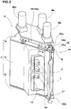
Fig. 1 is a perspective view of a system for measuring a tread profile as an embodiment of the present invention. -
Fig. 2 is a schematic plan view thereof. -
Fig. 3 is a perspective view of the laser measuring apparatus showing a state in which the shutter is opened. -
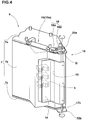
Fig. 4 is a perspective view of the laser measuring apparatus showing a state in which the shutter is closed. -
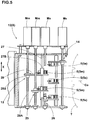
Fig. 5 is a schematic side view of the laser measuring apparatus showing the internal structure thereof. -
Fig. 6 is a perspective view for explaining a filtering function of a wide laser beam. -
Fig. 7 is a diagram for explaining a measuring process for determining a first tread radius TRs and a measuring process for determining a second tread radius TRM. -
Figs. 8(A) and 8(B) are diagrams for explaining a calibration process for the laser measuring apparatus. - Embodiments of present invention will now be described in detail in conjunction with accompanying drawings.
- According to the present invention, a system 1 for measuring a tread profile of a tire T comprises a
tire holding device 2, and alaser measuring apparatus 3. - The tire T as an object to be measured is a pneumatic tire, for example, a passenger car tire provided in the tread surface Ts with circumferentially extending ribs R, for example, a center rib Rc, two middle ribs Rm, and two axially outermost shoulder ribs Rs.
- The
tire holding device 2 comprises, as shown inFig.1 , atire support shaft 4 for supporting the tire T rotatably around the tire rotational axis j. - In this example, as shown in
Figs.1 and2 , the tire T which is mounted on a rim is horizontally supported by thetire support shaft 4. But, it is also possible to configure the system 1 for measuring a tread profile such that thetire support shaft 4 supports the tire T vertically. - The
tire holding device 2 further comprises
a drive unit (not shown) for rotating thetire support shaft 4 at a predetermined rotational speed which comprises a motor such as electric motor. - Instead of the drive unit for rotating the
tire support shaft 4, it may be possible to use a road wheel which is driven to rotate and to which the tread portion of the tire T is pressed so that the tire T is rotated thereby. - The
laser measuring apparatus 3 comprises: - at least three (in this embodiment five) laser distance measuring
devices 5 for measuring radial distances to the tread surface Ts of the held tire T from their respective positions; - an
insulating wall 7 enclosing the laserdistance measuring devices 5; - a
temperature controller 6 for controlling the temperature of gas (air) in the interior of theinsulating wall 7; and - a computing device (not shown) for calculating the tread profile based on data about the radial distances measured by the laser
distance measuring devices 5. - a
main frame 8; - a first
movable frame 10 supported by themain frame 8 through aguide device 9 movably in a direction perpendicular to the tire axial direction X; and - a second
movable frame 12 supported by the firstmovable frame 10 through aguide device 11 movably in the tire axial direction X. - The
temperature controller 6 comprises an air-conditioning andheating machine 6a, and anair duct 6b for sending the air whose temperature is controlled by the air-conditioning andheating machine 6a toward the laserdistance measuring devices 5 in order to keep the air surrounding the laser distance measuringdevices 5 within a narrow range, preferably at a predetermined constant temperature. Incidentally, a flexible stretchable duct made from accordion-folding material is used an theair duct 6b, for example. - On the second
movable frame 12, the laser distance measuringdevices 5 and theinsulating wall 7 are mounted. - As shown in
Fig. 3 , theinsulating wall 7 in this example includes anupper wall 7a above the laserdistance measuring devices 5, alower wall 7c under the laserdistance measuring devices 5, and a side wall 7b extending between theupper wall 7a and thelower wall 7c. Theinsulating wall 7 encloses all of the laser distance measuringdevices 5. - Preferably, the
insulating wall 7 is formed from a material or materials having heat insulation property in order to effectively keep the temperature of the interior constant. - The
insulating wall 7 is provided with
aaperture 13 through which the laser beams L of the laser distance measuringdevices 5 pass,
ashutter 14 for closing/opening theaperture 13, and
aninlet 15 for taking the air supplied from thetemperature controller 6 into the interior. - In this embodiment, the
aperture 13 and theinlet 15 are formed in the side wall 7b. - To the
inlet 15, the above-mentionedair duct 6b is connected through aflared part 6d whose cross sectional area is gradually increased toward theinlet 15 as shown inFig. 1 in order that the conditioned air is distributed evenly across the inside of theinsulating wall 7. - The
shutter 14 is made of, for example, a metal material. Preferably. a sheet of heat insulating material is applied to one side of theshutter 14. - In this example, the
shutter 14 is formed from a plate material which is folded to have a Z-shaped cross section as shown inFig. 3 . - On the second
movable frame 12, a shutter opening/closing device 16 for opening/closing theshutter 14 is mounted. - In this embodiment, the shutter opening/
closing device 16 comprises arotatable shaft 17 and anactuator 19 for rotating therotatable shaft 17. - In this example, as shown in
Fig. 3 andFig. 4 , both ends of therotatable shaft 17 are respectively supported by asupport piece 20a provided on theupper wall 7a and asupport piece 20b provided on thelower wall 7c so that therotatable shaft 17 extends in the vertical direction along the side wall 7b. - The
shutter 14 is fixed to therotatable shaft 17 by an appropriate means, for example, rivet, welding, screw, press fitting or the like. - The
actuator 19 in this example is acylinder 19a having a piston rod. The piston rod is connected to therotatable shaft 17 through alinkage 18. Thelinkage 18 is made up of alink 18a one end of which is fixed to the piston rod of theactuator 19 and alink 18b one end of which is fixed to one end of therotatable shaft 17, and
the other end of thelink 18a and the other end of thelink 18b are pivotally connected to each other.
The end of theactuator 19 on the opposite side of the piston rod is pivotally supporting by theupper wall 7a of the insulatingwall 7.
Therefore, by the extension of thecylinder 19a, therotatable shaft 17 is rotated through thelinkage 18 so that theshutter 14 opens theaperture 13.
By the retraction of thecylinder 19a, therotatable shaft 17 is rotated so that theshutter 14 closes theaperture 13. - Aside from
such cylinder 19a actuated by pressurized fluid, it is also possible to use, as theactuator 19,
a mechanical linear actuator such as a ball screw in combination with the linkage,
a geared motor coupled with therotatable shaft 17 or the like - In this embodiment, as shown in
Fig. 2 , theguide device 9 comprises a guide rail extending straight in the direction Z, and a guide groove slidably fitted with the guide rail. Theguide device 11 comprises a guide rail extending straight in the direction X, and a guide groove slidably fitted with the guide rail. of course, theguide device - For the
guide device 9, a moving device is provided which comprises acylinder 9A mounted on themain frame 8 such that its piston rod is capable of extending and retracting in the direction Z, and the piston rod is connected to the firstmovable frame 10. Therefore, by the extension and retraction of thecylinder 9A, the firstmovable frame 10 is moved in the direction Z between the waiting position Q1 and the measuring position Q2. - For the
guide device 11, a moving device is provided which comprises
aball screw shaft 11A (Fig. 2 ) pivotally supported by the firstmovable frame 10 so as to extend in the tire axial direction X, a motor Mc for rotating theball screw shaft 11A, and
aball nut 11B engaging with theball screw shaft 11A and fixed to the secondmovable frame 12.
Therefore, by rotating theball screw shaft 11A with the motor MC, the secondmovable frame 12 is moved in the tire axial direction X - The laser
distance measuring devices 5 are arranged at intervals in the tire axial direction X. - In this embodiment, as shown in
Fig. 5 , five laserdistance measuring devices 5 are arranged, which are a central laserdistance measuring device 5c, two middle laserdistance measuring devices 5m one disposed each side thereof, and two outer laserdistance measuring devices 5s disposed axially outside the respectively middle laserdistance measuring devices 5m. - The central laser
distance measuring device 5c is fixed to the secondmovable frame 12 and is movable in the tire axial direction X together with the secondmovable frame 12. - Each of the middle laser
distance measuring devices 5m is supported by the secondmovable frame 12 through aguide device 25 so that each of the middle laserdistance measuring devices 5m is movable in the tire axial direction X relatively to the central laserdistance measuring device 5c. - Each of the outer laser
distance measuring devices 5s is supported by the secondmovable frame 12 through aguide device 26 so that each of the outer laserdistance measuring devices 5s is movable in the tire axial direction X relatively to the central laserdistance measuring device 5c as well as the middle laserdistance measuring devices 5m. - In this embodiment, as shown in
Fig. 5 , theguide devices 25 for the respective middle laserdistance measuring devices 5m include asingle guide shaft 27 in common.
Also, theguide devices 26 for the respective outer laserdistance measuring devices 5s include asingle guide shaft 27 in common.
Both ends of eachguide shaft 27 are respectively fixed to an upper part and lower part of the secondmovable frame 12 so that theguide shaft 27 extends in the direction X. - Each of the
guide devices - a slider part provided with a
guide hole 27B through which theguide shaft 27 passes slidably and fixed to an attachingplate 29 to which one laserdistance measuring device - a
ball nut 28B attached to the attachingplate 29; - a
ball screw shaft 28A engaging with theball nut 28B; and - a motor (Mm for 5m, Ms for 5s) for rotating the
ball screw shaft 28A. Therefore, the laserdistance measuring device guide shaft 27. - Thus, by moving the second
movable frame 12, the position of the central laserdistance measuring device 5c can be adjusted to a reference position which is for example set on the tire equator Co.
The positions of the middle laserdistance measuring devices 5m and the positions of the outer laserdistance measuring devices 5s can be separately adjusted to suitable measuring positions in relation to that of the central laserdistance measuring device 5c according to the tire size, the tread pattern and the like. - At the measuring position Q2, as shown in
Fig. 2 , the laserdistance measuring devices 5 are arranged so that the center axes of the laser beams L from therespective devices 5 are arranged in a line parallel with the tire axial direction X and within a single plane extending radially outwardly from the tire rotational axis j, in other words, a single plane including the tire rotational axis j. - As to the laser
distance measuring devices 5, it is desirable to use a laser distance measuring device capable of irradiating the laser beam L having a width w of not less than 5 mm as shown inFig. 6 .
By using such a laserdistance measuring device 5, owing to so called filtering function of the laser distance measuring device itself, a negative effect of asmall irregularity 30 of the tread surface Ts (for example, resulted from asipe 30a,slot 30b or the like) which exists well within the irradiation part La corresponding to the width w of the laser beam L can be removed from the measuring result.
If theirregularity 30 is large, for example, theirregularity 30 is anaxial groove 31, and there is a possibility that the entire irradiation part La is included in thegroove 31, the measuring result becomes noise data or invalid data. Such invalid data is removed through the after-mentioned smoothing processing by the use of a computing device. - According to the present invention, a method for measuring a tread profile comprises a temperature controlling process SA and a measuring process SB.
- In the temperature controlling process SA, the temperature of the inside of the insulating
wall 7 enclosing the laserdistance measuring devices 5 is controlled by the use of thetemperature controller 6 so that the temperature of the gas or air around the laserdistance measuring devices 5 is kept substantially constant in order to reduce variations of output data of the laserdistance measuring devices 5 and accurately measure the tread profile. - The temperature controlling process SA comprises: closing the
aperture 13 of the insulatingwall 7 with theshutter 14; and uncovering theaperture 13 by taking off theshutter 14. By activating theactuator 19, in this embodiment, by retracting the rod of thecylinder 19a, thelinkage 18 rotates therotatable shaft 17 together with theshutter 14 and theaperture 13 is closed. Further, by extending the rod of thecylinder 19a, therotatable shaft 17 is rotated together with theshutter 14 and theaperture 13 is uncovered. - On the other hand, the temperature of the air in the interior of the insulating
wall 7 is controlled by thetemperature controller 6. It is desirable that the temperature is kept within a range between a preset value + 1 degree C and the preset value - 1 degree C in order that the variations of the output data of the laserdistance measuring devices 5 due to their temperature dependency can be surely eliminated. For example, the preset value for the temperature, namely, the target temperature is 22 to 28 degrees C., preferably 24 to 26 degrees C., more preferably 25 degrees C. - In this embodiment, the indoor air existing outside the insulating
wall 7 is drawn into the air-conditioning andheating machine 6a of thetemperature controller 6, and temperature controlled, and then sent into the interior of the insulatingwall 7 through theinlet 15.
of course, it is also possible to construct thetemperature controller 6 as a circulation type such that the air existing in the interior of the insulatingwall 7 is drawn into the air-conditioning andheating machine 6a and then the temperature controlled air is returned to the interior of the insulatingwall 7. - During the
aperture 13 is uncovered by taking off theshutter 14, the interior of the insulatingwall 7 is continuously supplied with the temperature controlled air from thetemperature controller 6. - During the
aperture 13 is uncovered, the above-mentioned tread profile measuring process SB is carried out. - In this embodiment, the tread profile measuring process SB is for determining a tread radius TR. Further, as shown in
Fig. 7 , the process SB in this embodiment includes: a measuring process SB1 for determining a first tread radius TRs based on the measurements at the tread center (center rib Rc in this example) and two tread shoulder portions (two axially outermost shoulder ribs Rs in this example), and a measuring process SB2 for determining a second tread radius TRm based on the measurements at the tread center and two tread middle portions (two middle ribs Rm in this example). - According to conditions under which a tire is used, for example, whether the automobiles have to drive on the left-hand side or right-hand side, and whether or not the road surfaces are generally semicylindrically curved for rainwater drainage, the first tread radius TRs is useful for predicting the steering stability in some countries whereas the second tread radius TRm is useful for predicting the steering stability in other countries. Thus, it is preferably to measure the first and second tread radii TRs and TRm.
- Each tread profile measuring process SB, SB1, SB2 comprises a measuring step, an averaging step, and a computing step.
- In the measuring step, by the use of three of the five laser
distance measuring devices 5, radial distances measured from these laserdistance measuring devices 5 to the tread surface Ts of the tire T are measured at a number m of circumferentially different measuring positions while rotating the tire around its rotational axis. Thereby,
a first set of distance data y1 (y11, y12, y13 --- y1m) are obtained from the first laserdistance measuring device 5, a second set of distance data y2 (y21, y22, y23 --- y2m) are obtained from the second laserdistance measuring device 5 and a third set of distance data y3 (y31, y32, y33 --- y3m) are obtained from the third laserdistance measuring device 5. - For example, in the case of the measuring process SB1 for determining the first tread radius TRs,
distance data y1 (y11-y1m) from the central laserdistance measuring device 5c to the tread center (center rib Rc) are obtained,
distance data y2 (y21-y2m) from one of the outer laserdistance measuring devices 5s to the tread shoulder portion (the opposite shoulder rib Rs) are obtained, and
distance data y3 (y31-y3m) from the other outer laserdistance measuring device 5s to the other tread shoulder portion (the opposite shoulder rib Rs) are obtained. - In the averaging step, firstly,
for each set of the number m of distance data y, namely, a first set of distance data y11-y1m, a second set of distance data y21-y2m, and a third set of distance data y31-y3m,
a smoothing processing is carried out, which is for removing therefrom the above-mentioned invalid data resulting from large irregularity 30 (such as theaxial groove 31 in this example). - Then, each set of the distance data y1, y2, y3 excluding the invalid data if any, are averaged to obtain an average value y1N, y2N, y3N.
- The smoothing processing carried out for each set n (n=1, 2, 3) of the number m of radial distance data yn1-ynm is as follows. (hereinafter each of the number m of the data or each measured distance is expressed as yn[i] wherein i=1, 2, 3 -- m in chronological order)
The number m is, for example, set to be not less than 500. - For each data yn[i], a moving average yN[i] of a fixed number k of the previous data yn[i-1] through yn[i-k] is obtained. The moving average yN[i] is obtained as (summation of yn[i-1] through yn[i-k])/k.
- If the difference between yn[i] and yN[i] is larger than a predetermined threshold value, yn[i] is removed as invalid data from the set n of the distance data yn.
- If k >= i, then instead of the number k of the previous data yn[i-1] through yn[i-k], yn[i-1] through yn[1] and yn[m] through yn[m-(k-i)] are used.
- As to the threshold value, preferably set is a value more than the expected maximum magnitude of Radial Run Out (RR0) of the tire and less than the depth of the
axial groove 31 included in the measuring portion (for example ribs R). For example, a value of about 3.0 mm is set to the threshold value. - In the computing step, the tread radius TR is obtained as a radius of a circle passing through three points on the tread surface.
- In a x-y coordinate plane of which x-axis is in the tire axial direction X and y-axis is in the direction Y, the Y-coordinate values of the three points are given by the above-mentioned three average values y1N, y2N and y3N. The X-coordinate values of the three points are given by distances x1, x2 and x3 of the laser
distance measuring devices 5 relating to the average values y1N, y2N and y3N, respectively, which are measured in the tire axial direction from a reference position X (reference position X can be arbitrary defined) in the tire axial direction. Thus, the three points are expressed as P1(x1,y1N), P2(x2,y2N) and P3(x3,y3N).
The radius of a circle passing through P1(x1,y1N), P2(x2,y2N) and P3(x3,y3N) is computed as the tread radius TR. - The averaging step including the smoothing processing and the computing step are implemented by the computing device.
- Each tread profile measuring process SB, SB1, SB2 is implemented as explained above. In the case where the measuring process SB1 and the measuring process SB2 are implemented, it is not necessary to implement these processes SB1 and SB2 one after the other. It is possible to implement the processes SB1 and SB2 at the same time. In this case, the data and processing in connection with the central laser
distance measuring device 5c can be sheared between the processes SB1 and SB2. - After the measuring step of the tread profile measuring process SB, the
aperture 13 is closed so that the air in the interior of the insulatingwall 7 is kept at the preset temperature. As described above, during theaperture 13 is uncovered, namely, during measuring the distances, it is desirable that the interior of the insulatingwall 7 is supplied with the temperature controlled air from thetemperature controller 6. - In the closed state of the
aperture 13, the tire T held by thetire holding device 2 is exchanged for the next tire to be measured . - Preferably, the number m of the circumferentially different measuring positions corresponding to the number of a set of distance data is not more than 2000. Even if the number m is increased over 2000, the accuracy of the measured tread profile reaches a ceiling whereas the computational time and cost increase. If the number m is less than 500, there is a possibility that the accuracy is decreased, in particular, in the case of a tread pattern including a large number of axial grooves (large irregularity 30).
- The number k of the previous data is at least 2 and preferably at most 100. Even if the number k is increased over 100, the effect of the smoothing processing reaches a ceiling whereas the computational time and cost increase.
- The number of revolutions of the tire T during measuring the radial distances with the laser
distance measuring devices 5 is set in a range of from 20 to 3000 rpm for example. - Preferably, the width w of the laser beam L is not less than 10 % and not more than 70 % of the width WR of the rib R as the measuring object in order to effectively utilize the above-mentioned filtering function of the laser distance measuring device itself. If the width W of the laser beam L is less than 10 % of the rib width WR or less than 5 mm, it becomes difficult to filter out the irradiation part La such as
sipe 30a and cut 30b. If the width w is more than 70 % of the rib width WR, there is a possibility that the laser beam L scans off the edge of the rib R, and the variation of the output data of the laserdistance measuring device 5 is increased. - According to the present invention, at least three laser
distance measuring devices 5 are used simultaneously. Therefore, it is preferable that the method for measuring the tread profile include a calibration process for calibrating the laser distance measuring devices before measuring the tread profile, using acalibration tool 35. - As schematically shown in
Fig. 8 , thecalibration tool 35 comprises acylindrical base part 36 supported by thetire support shaft 4 coaxially therewith and rotatably therearound, and a plurality ofreflector plates 37 fixed to thebase part 36. - The
reflector plates 37 are arranged around thetire support shaft 4 at intervals as shown inFig. 8(A) .
Eachreflector plate 37 has a reflecting surface extending along thetire support shaft 4 to cover all of the laserdistance measuring devices 5 as shown inFig. 8(B) .
The reflecting surfaces of thereflector plates 37 are placed at different radial distances from theaxis 4i of thetire support shaft 4 corresponding to the tire rotational axis j. Each reflecting surface is preferably formed by a part of the surface of a circular cylinder which is coaxial with thetire support shaft 4 in order to facilitate the position adjustment for thereflector plate 37.
In this embodiment, thereflector plates 37 are
afirst reflector plate 37a having a reflecting surface at a radial distance F1 from theaxis 4i of thetire support shaft 4 corresponding to the tire rotational axis j,
asecond reflector plate 37b having a reflecting surface at a radial distance F2 larger than the radial distance F1 of thefirst reflector plate 37a, and
athird reflector plate 37c having a reflecting surface at the radial distance F3 smaller than the radial distance F1 of thefirst reflector plate 37a.
As explained above, the reflecting surfaces of the first-third reflector plates - In the calibration process, the
first reflector plate 37a is positioned at the measuring position, and by the use of thefirst reflector plate 37a, the origin of each laserdistance measuring device 5 is calibrated.
Then, thecalibration tool 35 is rotated so that the second andthird reflector plates third reflector plates distance measuring device 5 is calibrated for the observed data. - While description has been made of one particularly preferable embodiment of the present invention, the illustrated embodiment should not be construed as to limit the scope of the present invention; various modifications are possible without departing from the scope of the present invention.
-
- 1
- system for measuring a tread profile of a tire
- 5
- laser distance measuring device
- T
- tire
- 6
- temperature controller
- 7
- insulating wall
- 13
- aperture
- 14
- shutter
Claims (3)
- A system (1) for measuring a tread profile of a tire (T) comprising
a tire holding device (2) comprising a tire support shaft (4) for supporting the tire (T) rotatably around the tire rotational axis (j),
a plurality of laser distance measuring devices (5) arranged along the axial direction of the tire (T) and oriented toward the tread portion of the tire (T) in order to measure distances to the tread portion, characterised in that the system further comprises an insulating wall (7) enclosing the laser distance measuring devices (5),
the insulating wall (7) provided with an aperture (13) through which laser beams (L) of the laser distance measuring devices (5) can pass, and a shutter (14) configured to close the aperture (13), and
a temperature controller (6) for controlling the temperature of a gas surrounding the laser distance measuring devices (5) in the insulating wall (7),
wherein the temperature controller (6) includes a cooling system and is configured to continuously supply temperature controlled air to the interior of the insulating wall (7) when the aperture (13) is uncovered by taking off the shutter (14). - A method for measuring a tread profile of a tire (T) by the use of the system (1) as set forth in claim 1, comprising
keeping the temperature of the gas surrounding the laser distance measuring devices (5) in the insulating wall (7) at a substantially constant temperature by the use of the temperature controller (6) so as to reduce variations of data output from the laser distance measuring devices (5) due to variations of the temperature of the laser distance measuring devices (5). - The method for measuring a tread profile of a tire (T) according to claim 2, wherein said substantially constant temperature is a preset targeted temperature plus/minus 1 degree C.
Applications Claiming Priority (1)
| Application Number | Priority Date | Filing Date | Title |
|---|---|---|---|
| JP2014114282A JP6159294B2 (en) | 2014-06-02 | 2014-06-02 | Tire tread shape measuring method and tread shape measuring apparatus used therefor |
Publications (2)
| Publication Number | Publication Date |
|---|---|
| EP2952871A1 EP2952871A1 (en) | 2015-12-09 |
| EP2952871B1 true EP2952871B1 (en) | 2018-10-10 |
Family
ID=53181162
Family Applications (1)
| Application Number | Title | Priority Date | Filing Date |
|---|---|---|---|
| EP15168265.5A Active EP2952871B1 (en) | 2014-06-02 | 2015-05-19 | System and method for measuring tire tread profile |
Country Status (3)
| Country | Link |
|---|---|
| EP (1) | EP2952871B1 (en) |
| JP (1) | JP6159294B2 (en) |
| CN (1) | CN105180833B (en) |
Families Citing this family (5)
| Publication number | Priority date | Publication date | Assignee | Title |
|---|---|---|---|---|
| CN106197275B (en) * | 2016-07-21 | 2019-03-12 | 天津大学 | Any face heart in blind cylindrical hole center is extracted in radiographic measurement sits calibration method |
| JP7212559B2 (en) * | 2019-03-18 | 2023-01-25 | 住友重機械工業株式会社 | Shape measuring device and shape measuring method |
| CN111238834A (en) * | 2020-01-20 | 2020-06-05 | 东莞市秉能橡胶有限公司 | Tire measuring method |
| CN114264234A (en) * | 2021-12-24 | 2022-04-01 | 哈尔滨工业大学芜湖机器人产业技术研究院 | Non-contact impeller runout detection system and method |
| CN116026280B (en) * | 2023-03-29 | 2023-07-04 | 中策橡胶集团股份有限公司 | Automatic detection equipment and detection method for stress and strain of tire sidewall |
Citations (1)
| Publication number | Priority date | Publication date | Assignee | Title |
|---|---|---|---|---|
| WO2012074527A1 (en) * | 2010-12-02 | 2012-06-07 | Michelin Recherche Et Technique, S.A. | Method for prediction and control of tire uniformity parameters from crown thickness variation |
Family Cites Families (10)
| Publication number | Priority date | Publication date | Assignee | Title |
|---|---|---|---|---|
| JPS5943307A (en) * | 1982-09-03 | 1984-03-10 | Sumitomo Rubber Ind Ltd | Method and apparatus for measuring size of tire |
| US5636026A (en) * | 1995-03-16 | 1997-06-03 | International Electronic Machines Corporation | Method and system for contactless measurement of railroad wheel characteristics |
| JP4580221B2 (en) | 2004-11-26 | 2010-11-10 | 住友ゴム工業株式会社 | Tread radius measuring jig |
| JP2006308320A (en) * | 2005-04-26 | 2006-11-09 | Sumitomo Rubber Ind Ltd | Tire compound measuring device |
| JP2008116352A (en) * | 2006-11-06 | 2008-05-22 | Ishikawajima Constr Materials Co Ltd | Laser type displacement measurement device and dimension variation measurement method using it |
| JP2008281438A (en) * | 2007-05-10 | 2008-11-20 | Bridgestone Corp | Method and apparatus for measuring vertical vibration of pneumatic tire |
| EP1995083B1 (en) * | 2007-05-23 | 2011-08-31 | Snap-on Equipment Srl a unico socio | Method of and apparatus for determining geometrical dimension of a vehicle wheel comprising optical sensors |
| NL2005570C2 (en) * | 2009-12-31 | 2011-07-04 | Volkerrail Nederland B V | Train with optical measuring implement and method. |
| JP5726045B2 (en) * | 2011-11-07 | 2015-05-27 | 株式会社神戸製鋼所 | Tire shape inspection method and tire shape inspection device |
| JP5837952B2 (en) * | 2014-03-07 | 2015-12-24 | 住友ゴム工業株式会社 | Tire tread radius measuring method and tread radius measuring apparatus used therefor |
-
2014
- 2014-06-02 JP JP2014114282A patent/JP6159294B2/en active Active
-
2015
- 2015-04-27 CN CN201510205478.2A patent/CN105180833B/en active Active
- 2015-05-19 EP EP15168265.5A patent/EP2952871B1/en active Active
Patent Citations (1)
| Publication number | Priority date | Publication date | Assignee | Title |
|---|---|---|---|---|
| WO2012074527A1 (en) * | 2010-12-02 | 2012-06-07 | Michelin Recherche Et Technique, S.A. | Method for prediction and control of tire uniformity parameters from crown thickness variation |
Also Published As
| Publication number | Publication date |
|---|---|
| JP2015227847A (en) | 2015-12-17 |
| JP6159294B2 (en) | 2017-07-05 |
| CN105180833A (en) | 2015-12-23 |
| EP2952871A1 (en) | 2015-12-09 |
| CN105180833B (en) | 2019-06-14 |
Similar Documents
| Publication | Publication Date | Title |
|---|---|---|
| EP2952871B1 (en) | System and method for measuring tire tread profile | |
| US5789668A (en) | Apparatus and related methods for obtaining tire profiles including the tread and both sidewalls | |
| EP3093611B1 (en) | Measuring method and device to measure the straightness error of bars and pipes | |
| JP6420639B2 (en) | Tread shape measurement method | |
| EP2950045B1 (en) | Device and method for detecting a normal-line direction of a curved surface and corresponding processing device | |
| JP6005871B2 (en) | Method, processing apparatus, and processing system for automatically surface processing of large molded member of wind power generator | |
| JP5946424B2 (en) | Tire testing machine | |
| CA2804309C (en) | Wind tunnel model measuring system and method | |
| CA3094679A1 (en) | Insertion apparatus for use with rotary machines | |
| WO2015133027A1 (en) | Tire tread radius measurement method and tread radius measurement device used in same | |
| EP2601476B1 (en) | Calibration device for measurement gauges of the diameter and other geometrical characteristics of cylinders | |
| JP2009541751A (en) | Method and apparatus for adjusting the steering wheel of a vehicle | |
| JPWO2006115203A1 (en) | Method and apparatus for detecting abnormality in outer shape of tire side portion | |
| TWI521260B (en) | Stage and apparatus for repairing curved display | |
| JP2008196881A (en) | Device and method for measuring thickness distribution of cross section of tire | |
| CN114952089B (en) | Cone barrel blade mounting method and cone barrel blade mounting device | |
| EP3910433A1 (en) | Methods of performing a plurality of operations within a region of a part utilizing an end effector of a robot and robots that perform the methods | |
| KR100509915B1 (en) | Multi correction for hot steel shape measurement | |
| CN109282742A (en) | Hole inner diameter measuring device and measurement method of the blind hole depth greater than 2 meters | |
| CN107438750A (en) | method and apparatus for measuring long profile | |
| KR100685052B1 (en) | Device for measuring the center position of strip | |
| KR200237798Y1 (en) | A rotary thermometer | |
| US20110037989A1 (en) | Measurement arrangement with a measurement head in order to carry out inspection measurement | |
| CN214792935U (en) | Air conditioner pipeline multi-angle welding detects frock | |
| JP4380941B2 (en) | Inspection device |
Legal Events
| Date | Code | Title | Description |
|---|---|---|---|
| PUAI | Public reference made under article 153(3) epc to a published international application that has entered the european phase |
Free format text: ORIGINAL CODE: 0009012 |
|
| AK | Designated contracting states |
Kind code of ref document: A1 Designated state(s): AL AT BE BG CH CY CZ DE DK EE ES FI FR GB GR HR HU IE IS IT LI LT LU LV MC MK MT NL NO PL PT RO RS SE SI SK SM TR |
|
| AX | Request for extension of the european patent |
Extension state: BA ME |
|
| 17P | Request for examination filed |
Effective date: 20160608 |
|
| RBV | Designated contracting states (corrected) |
Designated state(s): AL AT BE BG CH CY CZ DE DK EE ES FI FR GB GR HR HU IE IS IT LI LT LU LV MC MK MT NL NO PL PT RO RS SE SI SK SM TR |
|
| GRAP | Despatch of communication of intention to grant a patent |
Free format text: ORIGINAL CODE: EPIDOSNIGR1 |
|
| STAA | Information on the status of an ep patent application or granted ep patent |
Free format text: STATUS: GRANT OF PATENT IS INTENDED |
|
| INTG | Intention to grant announced |
Effective date: 20180502 |
|
| RAP1 | Party data changed (applicant data changed or rights of an application transferred) |
Owner name: SUMITOMO RUBBER INDUSTRIES, LTD. |
|
| GRAS | Grant fee paid |
Free format text: ORIGINAL CODE: EPIDOSNIGR3 |
|
| GRAA | (expected) grant |
Free format text: ORIGINAL CODE: 0009210 |
|
| STAA | Information on the status of an ep patent application or granted ep patent |
Free format text: STATUS: THE PATENT HAS BEEN GRANTED |
|
| AK | Designated contracting states |
Kind code of ref document: B1 Designated state(s): AL AT BE BG CH CY CZ DE DK EE ES FI FR GB GR HR HU IE IS IT LI LT LU LV MC MK MT NL NO PL PT RO RS SE SI SK SM TR |
|
| REG | Reference to a national code |
Ref country code: GB Ref legal event code: FG4D |
|
| REG | Reference to a national code |
Ref country code: CH Ref legal event code: EP Ref country code: AT Ref legal event code: REF Ref document number: 1051808 Country of ref document: AT Kind code of ref document: T Effective date: 20181015 |
|
| REG | Reference to a national code |
Ref country code: IE Ref legal event code: FG4D |
|
| REG | Reference to a national code |
Ref country code: DE Ref legal event code: R096 Ref document number: 602015017720 Country of ref document: DE |
|
| REG | Reference to a national code |
Ref country code: NL Ref legal event code: MP Effective date: 20181010 |
|
| REG | Reference to a national code |
Ref country code: LT Ref legal event code: MG4D |
|
| REG | Reference to a national code |
Ref country code: AT Ref legal event code: MK05 Ref document number: 1051808 Country of ref document: AT Kind code of ref document: T Effective date: 20181010 |
|
| PG25 | Lapsed in a contracting state [announced via postgrant information from national office to epo] |
Ref country code: NL Free format text: LAPSE BECAUSE OF FAILURE TO SUBMIT A TRANSLATION OF THE DESCRIPTION OR TO PAY THE FEE WITHIN THE PRESCRIBED TIME-LIMIT Effective date: 20181010 |
|
| PG25 | Lapsed in a contracting state [announced via postgrant information from national office to epo] |
Ref country code: NO Free format text: LAPSE BECAUSE OF FAILURE TO SUBMIT A TRANSLATION OF THE DESCRIPTION OR TO PAY THE FEE WITHIN THE PRESCRIBED TIME-LIMIT Effective date: 20190110 Ref country code: LT Free format text: LAPSE BECAUSE OF FAILURE TO SUBMIT A TRANSLATION OF THE DESCRIPTION OR TO PAY THE FEE WITHIN THE PRESCRIBED TIME-LIMIT Effective date: 20181010 Ref country code: HR Free format text: LAPSE BECAUSE OF FAILURE TO SUBMIT A TRANSLATION OF THE DESCRIPTION OR TO PAY THE FEE WITHIN THE PRESCRIBED TIME-LIMIT Effective date: 20181010 Ref country code: PL Free format text: LAPSE BECAUSE OF FAILURE TO SUBMIT A TRANSLATION OF THE DESCRIPTION OR TO PAY THE FEE WITHIN THE PRESCRIBED TIME-LIMIT Effective date: 20181010 Ref country code: BG Free format text: LAPSE BECAUSE OF FAILURE TO SUBMIT A TRANSLATION OF THE DESCRIPTION OR TO PAY THE FEE WITHIN THE PRESCRIBED TIME-LIMIT Effective date: 20190110 Ref country code: AT Free format text: LAPSE BECAUSE OF FAILURE TO SUBMIT A TRANSLATION OF THE DESCRIPTION OR TO PAY THE FEE WITHIN THE PRESCRIBED TIME-LIMIT Effective date: 20181010 Ref country code: ES Free format text: LAPSE BECAUSE OF FAILURE TO SUBMIT A TRANSLATION OF THE DESCRIPTION OR TO PAY THE FEE WITHIN THE PRESCRIBED TIME-LIMIT Effective date: 20181010 Ref country code: IS Free format text: LAPSE BECAUSE OF FAILURE TO SUBMIT A TRANSLATION OF THE DESCRIPTION OR TO PAY THE FEE WITHIN THE PRESCRIBED TIME-LIMIT Effective date: 20190210 Ref country code: LV Free format text: LAPSE BECAUSE OF FAILURE TO SUBMIT A TRANSLATION OF THE DESCRIPTION OR TO PAY THE FEE WITHIN THE PRESCRIBED TIME-LIMIT Effective date: 20181010 Ref country code: FI Free format text: LAPSE BECAUSE OF FAILURE TO SUBMIT A TRANSLATION OF THE DESCRIPTION OR TO PAY THE FEE WITHIN THE PRESCRIBED TIME-LIMIT Effective date: 20181010 |
|
| PG25 | Lapsed in a contracting state [announced via postgrant information from national office to epo] |
Ref country code: AL Free format text: LAPSE BECAUSE OF FAILURE TO SUBMIT A TRANSLATION OF THE DESCRIPTION OR TO PAY THE FEE WITHIN THE PRESCRIBED TIME-LIMIT Effective date: 20181010 Ref country code: SE Free format text: LAPSE BECAUSE OF FAILURE TO SUBMIT A TRANSLATION OF THE DESCRIPTION OR TO PAY THE FEE WITHIN THE PRESCRIBED TIME-LIMIT Effective date: 20181010 Ref country code: RS Free format text: LAPSE BECAUSE OF FAILURE TO SUBMIT A TRANSLATION OF THE DESCRIPTION OR TO PAY THE FEE WITHIN THE PRESCRIBED TIME-LIMIT Effective date: 20181010 Ref country code: PT Free format text: LAPSE BECAUSE OF FAILURE TO SUBMIT A TRANSLATION OF THE DESCRIPTION OR TO PAY THE FEE WITHIN THE PRESCRIBED TIME-LIMIT Effective date: 20190210 Ref country code: GR Free format text: LAPSE BECAUSE OF FAILURE TO SUBMIT A TRANSLATION OF THE DESCRIPTION OR TO PAY THE FEE WITHIN THE PRESCRIBED TIME-LIMIT Effective date: 20190111 |
|
| REG | Reference to a national code |
Ref country code: DE Ref legal event code: R097 Ref document number: 602015017720 Country of ref document: DE |
|
| PG25 | Lapsed in a contracting state [announced via postgrant information from national office to epo] |
Ref country code: IT Free format text: LAPSE BECAUSE OF FAILURE TO SUBMIT A TRANSLATION OF THE DESCRIPTION OR TO PAY THE FEE WITHIN THE PRESCRIBED TIME-LIMIT Effective date: 20181010 Ref country code: DK Free format text: LAPSE BECAUSE OF FAILURE TO SUBMIT A TRANSLATION OF THE DESCRIPTION OR TO PAY THE FEE WITHIN THE PRESCRIBED TIME-LIMIT Effective date: 20181010 Ref country code: CZ Free format text: LAPSE BECAUSE OF FAILURE TO SUBMIT A TRANSLATION OF THE DESCRIPTION OR TO PAY THE FEE WITHIN THE PRESCRIBED TIME-LIMIT Effective date: 20181010 |
|
| PLBE | No opposition filed within time limit |
Free format text: ORIGINAL CODE: 0009261 |
|
| STAA | Information on the status of an ep patent application or granted ep patent |
Free format text: STATUS: NO OPPOSITION FILED WITHIN TIME LIMIT |
|
| PG25 | Lapsed in a contracting state [announced via postgrant information from national office to epo] |
Ref country code: RO Free format text: LAPSE BECAUSE OF FAILURE TO SUBMIT A TRANSLATION OF THE DESCRIPTION OR TO PAY THE FEE WITHIN THE PRESCRIBED TIME-LIMIT Effective date: 20181010 Ref country code: EE Free format text: LAPSE BECAUSE OF FAILURE TO SUBMIT A TRANSLATION OF THE DESCRIPTION OR TO PAY THE FEE WITHIN THE PRESCRIBED TIME-LIMIT Effective date: 20181010 Ref country code: SM Free format text: LAPSE BECAUSE OF FAILURE TO SUBMIT A TRANSLATION OF THE DESCRIPTION OR TO PAY THE FEE WITHIN THE PRESCRIBED TIME-LIMIT Effective date: 20181010 Ref country code: SK Free format text: LAPSE BECAUSE OF FAILURE TO SUBMIT A TRANSLATION OF THE DESCRIPTION OR TO PAY THE FEE WITHIN THE PRESCRIBED TIME-LIMIT Effective date: 20181010 |
|
| 26N | No opposition filed |
Effective date: 20190711 |
|
| PG25 | Lapsed in a contracting state [announced via postgrant information from national office to epo] |
Ref country code: SI Free format text: LAPSE BECAUSE OF FAILURE TO SUBMIT A TRANSLATION OF THE DESCRIPTION OR TO PAY THE FEE WITHIN THE PRESCRIBED TIME-LIMIT Effective date: 20181010 |
|
| REG | Reference to a national code |
Ref country code: CH Ref legal event code: PL |
|
| GBPC | Gb: european patent ceased through non-payment of renewal fee |
Effective date: 20190519 |
|
| PG25 | Lapsed in a contracting state [announced via postgrant information from national office to epo] |
Ref country code: LI Free format text: LAPSE BECAUSE OF NON-PAYMENT OF DUE FEES Effective date: 20190531 Ref country code: CH Free format text: LAPSE BECAUSE OF NON-PAYMENT OF DUE FEES Effective date: 20190531 Ref country code: MC Free format text: LAPSE BECAUSE OF FAILURE TO SUBMIT A TRANSLATION OF THE DESCRIPTION OR TO PAY THE FEE WITHIN THE PRESCRIBED TIME-LIMIT Effective date: 20181010 |
|
| REG | Reference to a national code |
Ref country code: BE Ref legal event code: MM Effective date: 20190531 |
|
| PG25 | Lapsed in a contracting state [announced via postgrant information from national office to epo] |
Ref country code: LU Free format text: LAPSE BECAUSE OF NON-PAYMENT OF DUE FEES Effective date: 20190519 |
|
| PG25 | Lapsed in a contracting state [announced via postgrant information from national office to epo] |
Ref country code: TR Free format text: LAPSE BECAUSE OF FAILURE TO SUBMIT A TRANSLATION OF THE DESCRIPTION OR TO PAY THE FEE WITHIN THE PRESCRIBED TIME-LIMIT Effective date: 20181010 |
|
| PG25 | Lapsed in a contracting state [announced via postgrant information from national office to epo] |
Ref country code: GB Free format text: LAPSE BECAUSE OF NON-PAYMENT OF DUE FEES Effective date: 20190519 Ref country code: IE Free format text: LAPSE BECAUSE OF NON-PAYMENT OF DUE FEES Effective date: 20190519 |
|
| PG25 | Lapsed in a contracting state [announced via postgrant information from national office to epo] |
Ref country code: BE Free format text: LAPSE BECAUSE OF NON-PAYMENT OF DUE FEES Effective date: 20190531 |
|
| PG25 | Lapsed in a contracting state [announced via postgrant information from national office to epo] |
Ref country code: CY Free format text: LAPSE BECAUSE OF FAILURE TO SUBMIT A TRANSLATION OF THE DESCRIPTION OR TO PAY THE FEE WITHIN THE PRESCRIBED TIME-LIMIT Effective date: 20181010 |
|
| PG25 | Lapsed in a contracting state [announced via postgrant information from national office to epo] |
Ref country code: HU Free format text: LAPSE BECAUSE OF FAILURE TO SUBMIT A TRANSLATION OF THE DESCRIPTION OR TO PAY THE FEE WITHIN THE PRESCRIBED TIME-LIMIT; INVALID AB INITIO Effective date: 20150519 Ref country code: MT Free format text: LAPSE BECAUSE OF FAILURE TO SUBMIT A TRANSLATION OF THE DESCRIPTION OR TO PAY THE FEE WITHIN THE PRESCRIBED TIME-LIMIT Effective date: 20181010 |
|
| PG25 | Lapsed in a contracting state [announced via postgrant information from national office to epo] |
Ref country code: MK Free format text: LAPSE BECAUSE OF FAILURE TO SUBMIT A TRANSLATION OF THE DESCRIPTION OR TO PAY THE FEE WITHIN THE PRESCRIBED TIME-LIMIT Effective date: 20181010 |
|
| REG | Reference to a national code |
Ref country code: FR Ref legal event code: PLFP Year of fee payment: 9 |
|
| PGFP | Annual fee paid to national office [announced via postgrant information from national office to epo] |
Ref country code: FR Payment date: 20230411 Year of fee payment: 9 Ref country code: DE Payment date: 20230331 Year of fee payment: 9 |