EP2676698A1 - Adapter zum mechanischen und elektrischen Anschluss einer implantierbaren Elektrode an mindestens einen Testanschluss-Kontakt - Google Patents
Adapter zum mechanischen und elektrischen Anschluss einer implantierbaren Elektrode an mindestens einen Testanschluss-Kontakt Download PDFInfo
- Publication number
- EP2676698A1 EP2676698A1 EP13168212.2A EP13168212A EP2676698A1 EP 2676698 A1 EP2676698 A1 EP 2676698A1 EP 13168212 A EP13168212 A EP 13168212A EP 2676698 A1 EP2676698 A1 EP 2676698A1
- Authority
- EP
- European Patent Office
- Prior art keywords
- contact
- adapter
- connection
- connection plug
- receiving tray
- Prior art date
- Legal status (The legal status is an assumption and is not a legal conclusion. Google has not performed a legal analysis and makes no representation as to the accuracy of the status listed.)
- Granted
Links
- 238000012360 testing method Methods 0.000 title claims abstract description 24
- 241000270728 Alligator Species 0.000 claims description 4
- 239000012777 electrically insulating material Substances 0.000 claims description 3
- 238000006073 displacement reaction Methods 0.000 claims description 2
- 238000012546 transfer Methods 0.000 claims description 2
- 241000270722 Crocodylidae Species 0.000 description 17
- LNNWVNGFPYWNQE-GMIGKAJZSA-N desomorphine Chemical compound C1C2=CC=C(O)C3=C2[C@]24CCN(C)[C@H]1[C@@H]2CCC[C@@H]4O3 LNNWVNGFPYWNQE-GMIGKAJZSA-N 0.000 description 17
- 230000000638 stimulation Effects 0.000 description 7
- 239000000243 solution Substances 0.000 description 6
- KWGRBVOPPLSCSI-WPRPVWTQSA-N (-)-ephedrine Chemical compound CN[C@@H](C)[C@H](O)C1=CC=CC=C1 KWGRBVOPPLSCSI-WPRPVWTQSA-N 0.000 description 2
- 238000003780 insertion Methods 0.000 description 2
- 230000037431 insertion Effects 0.000 description 2
- 230000006978 adaptation Effects 0.000 description 1
- 238000004873 anchoring Methods 0.000 description 1
- 230000001746 atrial effect Effects 0.000 description 1
- 230000000747 cardiac effect Effects 0.000 description 1
- 238000010276 construction Methods 0.000 description 1
- 238000011161 development Methods 0.000 description 1
- 238000005516 engineering process Methods 0.000 description 1
- 238000002513 implantation Methods 0.000 description 1
- 238000002347 injection Methods 0.000 description 1
- 239000007924 injection Substances 0.000 description 1
- 238000001746 injection moulding Methods 0.000 description 1
- 239000000463 material Substances 0.000 description 1
- 238000000034 method Methods 0.000 description 1
- 239000002991 molded plastic Substances 0.000 description 1
- 230000035939 shock Effects 0.000 description 1
- 230000002861 ventricular Effects 0.000 description 1
Images




Classifications
-
- A—HUMAN NECESSITIES
- A61—MEDICAL OR VETERINARY SCIENCE; HYGIENE
- A61N—ELECTROTHERAPY; MAGNETOTHERAPY; RADIATION THERAPY; ULTRASOUND THERAPY
- A61N1/00—Electrotherapy; Circuits therefor
- A61N1/18—Applying electric currents by contact electrodes
- A61N1/32—Applying electric currents by contact electrodes alternating or intermittent currents
- A61N1/36—Applying electric currents by contact electrodes alternating or intermittent currents for stimulation
- A61N1/372—Arrangements in connection with the implantation of stimulators
-
- H—ELECTRICITY
- H01—ELECTRIC ELEMENTS
- H01R—ELECTRICALLY-CONDUCTIVE CONNECTIONS; STRUCTURAL ASSOCIATIONS OF A PLURALITY OF MUTUALLY-INSULATED ELECTRICAL CONNECTING ELEMENTS; COUPLING DEVICES; CURRENT COLLECTORS
- H01R13/00—Details of coupling devices of the kinds covered by groups H01R12/70 or H01R24/00 - H01R33/00
- H01R13/62—Means for facilitating engagement or disengagement of coupling parts or for holding them in engagement
-
- H—ELECTRICITY
- H01—ELECTRIC ELEMENTS
- H01R—ELECTRICALLY-CONDUCTIVE CONNECTIONS; STRUCTURAL ASSOCIATIONS OF A PLURALITY OF MUTUALLY-INSULATED ELECTRICAL CONNECTING ELEMENTS; COUPLING DEVICES; CURRENT COLLECTORS
- H01R24/00—Two-part coupling devices, or either of their cooperating parts, characterised by their overall structure
- H01R24/28—Coupling parts carrying pins, blades or analogous contacts and secured only to wire or cable
Definitions
- the invention relates to an adapter for the mechanical and electrical connection of an implantable electrode with its proximal, at least one terminal contact for an electrode surface of the electrode having terminal connector to at least one test terminal contact, in particular to a crocodile clip, a measuring device.
- implantable stimulation electrodes include sensing / pacing electrodes, shock electrodes, epicardial electrodes, endocardial electrodes, atrial or ventricular electrodes, unipolar or bipolar electrodes, etc.
- Such stimulation electrodes include one or more electrode surfaces at the distal end of the electrode and a connector plug at the proximal end of the electrode. The latter serves as an interface to the implantable stimulation device.
- the terminal plug of the electrode is temporarily connected to a measuring device, such as a patient system analyzer, so that a series of stimulation pulses of different energies or other test signals can be supplied to the preliminary inserted electrode.
- connection of this measuring device to the connection plug of the electrode is done with test terminal contacts, for example in the form of crocodile clips.
- connection of such test connection contacts with the connection plug of the electrode will be briefly illuminated below with reference to the example of crocodile clips.
- the direct connection of alligator clips to the connection plug is generally not very reliable, as the alligator clips can come loose from the connection plug during test operation.
- poor positioning of the alligator clips on the terminal contacts of the terminal connector may result in poor contact connection which may affect the tests and lead to incorrect conclusions, for example, on the positioning of the electrode.
- a faulty contact and short circuits can occur in careless use of such crocodile clips.
- the present invention seeks to provide an adapter for mechanical and electrical connection of an implantable electrode to a measuring device, the simple and safe adapter handling, in particular improved positioning of the terminal contacts of the electrode ensures the test terminal contacts of the measuring device to each other.
- the connector plug By inserting the connector plug in a defined in the adapter housing between the open and contact position stored storage receiving tray serves as a positioning aid for the connector plug, which satisfies the condition in the contact position of the receiving tray correctly associated with the test terminal contacts.
- the receiving tray takes on the connector plug in the correct position and leads its connection contacts defined in the adapter housing contact elements and exactly, so that a secure electrical contact to the measuring device, for example via Crocodile clips is made. Since the latter are not placed directly on the connection contacts of the connection plug of the electrode, the electrode connection plug is effectively protected against damage, such as scratches or deformations.
- the receiving tray different bearing structures on the adapter housing are conceivable, however, two advantageous embodiments are preferable.
- the receiving tray can be a sliding between the open and the contact position on the adapter housing drawer, the displacement direction then preferably transverse to the longitudinal direction of the connector plug runs.
- the receiving drawer can also be designed as a folding drawer pivotable between the two named positions, wherein the pivoting direction can in turn then run transversely to the longitudinal direction of the connection plug.
- the receiving tray can be fixed in the open and / or contact position relative to the adapter housing by latching. Preferably, both positions are rasterized.
- the locking function in the open position allows controlled positioning and insertion of the connection plug into the adapter.
- the locking of the closed receiving tray in the contact position prevents the accidental opening and falling out of the electrode from the adapter.
- Ease of use and handling safety of the adapter according to the invention can be further increased by the fact that the locking is releasable by a release button.
- the latter can be connected to the adapter housing via an integrally connected with these two spring tongue.
- the release button construction is thus to be realized by simple mold technology to be produced by injection molding of the adapter housing.
- connection contacts of the connection plug in the contact position of the receiving tray to the outside are complete coverable. This is an effective protection against contact when handling the electrode in conjunction with the adapter according to the invention.
- the receiving tray and the adapter housing frontally before the positionable in the receiving tray connector plug with an opening for free access to a guided through the connector plug central lumen of the electrode in both the open and in the contact position be provided.
- each contact surface is flanked by a corresponding guide for the test terminal contact.
- crocodile clips can thus be securely placed on the adapter and electrically connected to its contact element.
- connector plugs of implantable electrodes have multiple terminal contacts.
- the adapter according to the invention for such a connector plug have two contact elements, which are to be brought in each case on the one hand with a terminal contact of the connector plug in the receiving tray and on the other hand with a test terminal contact a measuring device in combination.
- the adapter housing has two or four contact elements for use in pacemaker or defibrillator electrodes, for example on. For other applications, eight or more contact elements are conceivable.
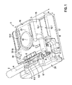
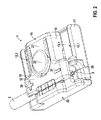
- the Fig. 1 to 7 show a first embodiment of an adapter 1 for the mechanical and electrical connection of a cut away in the drawings, implantable electrode 2 to a measuring device not shown in detail by means of test terminal contacts, as shown in FIG Fig. 5 and 10 in the form of crocodile clips 3, 4 are shown by way of example.
- the electrode 2 in this case has its particular in Fig. 1 . 8th and 13 recognizable proximal end to a connection plug 5, the four connection contacts 6.1, 6.2, 6.3 in the form of annular surfaces on the connector body 7 and a contact 6.4 has a pin 9 on the connector tip.
- the electrode 2 comprises a central lumen 8, which is led out at the end of the electrode 2 via the coaxial with the electrode 2 extending pin 9.
- the adapter housing 10 has an articulated outer shape, which can be described in the rough outline as a cuboid with a length L, width B and height H. It consists of an electrically insulating material, such as an injection molded plastic material.
- a circuit board 11 is used with two contact elements 12.1, 12.2 in the form of metallic contact strips, of which in the Fig. 1 to 4 and 6 serving for the connection of the crocodile clips 3, 4 serving, exposed contact surfaces 13.1, 13.2 are visible.
- the connection area to the connection plug 5 are fixed to the contact elements 12.1, 12.2 respectively to the circuit board 11 fixed spring contacts 14.1, 14.2 electrically connected to make the contact to the terminal contacts 6.3 and 6.4 of the electrode 2 with the adapter 1 closed (see Fig. 6 ).
- the guides formed by the adapter housing 10 through the side walls 15 of the structure 16 and the protruding narrow sides 17 take the "mouth" 18 of the crocodile clips 3, 4 on (see Fig. 5 and 12 ), wherein the clamping safety is still increased by the webs 24 on the underside of the adapter housing 10.
- connection plug 5 a receptacle 19 is provided in the adapter 1, which in the in Fig. 1 to 7 embodiment shown in a drawer 20 is arranged.
- This receptacle 19 corresponds to the shape of the connection plug 5, so that it is received in the correct position and exactly defined in the drawer 20, as this Fig. 1 shows.
- the drawer 20 is in the direction of the width B of the adapter housing 10 between the in Fig. 1 and 3 shown open position and the in Fig. 2 . 4 and 5 shown contact position variable, namely slidably mounted on corresponding guides 21 on the adapter housing 10.
- the drawer 20 In the open position according to Fig. 1 and 3 in which the connection plug 5 can be inserted into the receptacle 19, and in the in Fig. 2 and 4 shown contact position, the drawer 20 is locked relative to the adapter housing 10.
- the latching V is formed by a locking tongue 33 formed on the drawer 20, which is provided with a projection 34 in a latching recess 35 in the adapter housing 10 in front of a in Fig. 1 . 2 .
- release button 22 engages which is connected via an elastic spring tongue 23 to the adapter housing 10 in the direction of the height H displaced.
- the catch V can be canceled by the release button 22 by this pressed and the projection 34 so that it is lifted out of the recess 35.
- the drawer 20 is thus freely movable.
- the drawer 20 is inserted with the inserted connector plug 5 transversely to the longitudinal direction A in the adapter housing 10.
- contact position of the drawer 20 are then the two terminals 6.3 and 6.4 via the spring contacts 14.1, 14.2 of the contact elements 12.1, 12.2 led out electrically.
- FIG. 5 shows, one crocodile clip 3, 4 postponed. Their seat on the contact elements 12.1, 12.2 is still by the in Fig. 3 and 4 illustrated ridge-shaped forms 24 on the underside of the adapter housing 10 improved. These webs are intended to prevent the crocodile clips 3, 4 from slipping off. Since the crocodile clips 3, 4 are covered to the outside with their contacts through insulating shoes 25, a clean, protected against contact contact between a measuring device on the crocodile clips 3, 4 and the adapter 1 to the connector plug 5 is realized overall.
- the drawer 20 and the adapter housing 10 has an opening 26, via which the pin 9 with the lumen 8 of the electrode 2 in the in Fig. 2 . 4 and 5 shown contact position is freely accessible.
- the in Fig. 5 drawn stylet 27 simply by pulling on its handle 28 exchanged or otherwise operated without the positioning of the connector plug and adapter 1 would have to change something.
- a second embodiment of the adapter 1 ' is shown. This differs from the embodiment according to Fig. 1 to 7 in the version of the receiving tray.
- This is realized here by a folding drawer 29, which is pivotally mounted on the adapter housing 10 about a pivot axis S extending parallel to the length.
- the folding tray 29 In the in Fig. 8 and 10 shown open position, the folding tray 29 is folded up, so that the receptacle 19 from the side for the connection plug 5 of the electrode 2 is accessible (see Fig. 8 and 10 ).
- connection plug 5 inserted in the receptacle 19 is pushed into the adapter housing 10 and is connected there mechanically and electrically internally to the contact elements 12.1, 12.2.
- the latter are analogous to the embodiment according to Fig. 1 to 7 built and therefore require no further discussion.
- Fig. 9 . 11 and 12 is also locked. The solution of the locking takes place by a simple push or pull on the folding drawer 29. A release button is not provided here.
- Fig. 12 shows - even the adapter 1 'is designed so that via an opening 26, a stylet 27 can be maneuvered through its handle 28 during the connection of a measuring device by the crocodile clips 3, 4 in a suitable manner.
- Fig. 13 and 14 is a further embodiment of an adapter 1 "shown, the embodiment according to Fig. 1 to 7 equivalent.
- the only difference is that the release button 22 is omitted for the release of the locking of the drawer 20 in the open and contact position.
- These locks can - analogous to the embodiment according to the 8 to 12 - Be overcome by a simple train or pressure on the drawer 20.
- an adapter 1 "' is shown in the basic embodiment of the adapter 1 according to Fig. 1 to 7 corresponds, but is designed to contact all four terminals 6.1 to 6.4 of the connection plug 5.
- the adapter 1 matching components with identical reference numerals and require no further explanation.
- the contact elements 12.1 to 12.4 on the circuit board 11 are in turn analog in the interior of the adapter housing 10 Fig. 6 connected to spring contacts, which are connected to the individual connection contacts 6.1 to 6.4 in the in Fig. 15 shown closed position of the adapter 1 "'can be electrically connected.
Landscapes
- Health & Medical Sciences (AREA)
- Engineering & Computer Science (AREA)
- Biomedical Technology (AREA)
- Nuclear Medicine, Radiotherapy & Molecular Imaging (AREA)
- Radiology & Medical Imaging (AREA)
- Life Sciences & Earth Sciences (AREA)
- Animal Behavior & Ethology (AREA)
- General Health & Medical Sciences (AREA)
- Public Health (AREA)
- Veterinary Medicine (AREA)
- Electrotherapy Devices (AREA)
- Details Of Connecting Devices For Male And Female Coupling (AREA)
Abstract
Description
- Die Erfindung betrifft einen Adapter zum mechanischen und elektrischen Anschluss einer implantierbaren Elektrode mit ihrem proximalen, mindestens einen Anschluss-Kontakt für eine Elektrodenfläche der Elektrode aufweisenden Anschluss-Stecker an mindestens einen Testanschluss-Kontakt, insbesondere an eine Krokodilklemme, einer Messeinrichtung.
- Zum Hintergrund der Erfindung ist darauf zu verweisen, dass beispielsweise Herzschrittmacher oder sogenannte ICDs (Intra Cardiac Devices) implantierbare Stimulationselektroden zur elektrischen Verbindung der Stimulationseinrichtung mit einem bestimmten Körpergewebe aufweisen. So umfassen implantierbare Stimulationselektroden Mess-/Schrittmacher-Elektroden, Schockelektroden, epikardiale Elektroden, endokardiale Elektroden, atriale oder ventrikuläre Elektroden, uni- oder bipolare Elektroden usw.
- Solche Stimulationselektroden umfassen eine oder mehrere Elektrodenflächen am distalen Ende der Elektrode und einen Anschluss-Stecker am proximalen Ende der Elektrode. Letzterer dient als Schnittstelle zum implantierbaren Stimulationsgerät.
- Wenn dem Patienten eine implantierbare Elektrode eingesetzt wird, ist es in der Regel empfehlenswert, einige vorläufige Tests durchzuführen, bevor die Elektrode an ihrem endgültigen Platz verankert und der Anschluss-Stecker der Elektrode mit dem implantierten Stimulationsgerät verbunden wird. Zu diesem Zweck wird der Anschluss-Stecker der Elektrode zeitweise mit einer Messeinrichtung, wie beispielsweise einem Patienten-Systemanalysegerät, verbunden, so dass eine Reihe von Stimulationsimpulsen unterschiedlicher Energien oder andere Testsignale der vorläufig eingesetzten Elektrode zugeführt werden können.
- Der Anschluss dieser Messeinrichtung an den Anschluss-Stecker der Elektrode erfolgt mit Testanschluss-Kontakten beispielsweise in Form von Krokodilklemmen.
- Die Problematik der Verbindung solcher Testanschluss-Kontakte mit dem Anschluss-Stecker der Elektrode soll im Folgenden anhand des Beispiels von Krokodilklemmen kurz beleuchtet werden. So ist die direkte Anklipsung von Krokodilklemmen an den Anschluss-Stecker zum einen bereits generell wenig zuverlässig, da die Krokodilklemmen während des Testbetriebes sich vom Anschluss-Stecker lösen können. Darüber hinaus kann bei einer schlechten Positionierung der Krokodilklemmen an den Anschluss-Kontakten des Anschluss-Steckers eine schlechte Kontaktverbindung vorliegen, die die Tests beeinflussen und zu falschen Rückschlüssen beispielsweise auf die Positionierung der Elektrode führen können. Auch eine Fehlkontaktierung und Kurzschlüsse können bei unachtsamer Anwendung solcher Krokodilklemmen auftreten.
- Der Stand der Technik zeigt im Zusammenhang mit dieser Problematik einige Lösungsansätze. So offenbart die
US 7,777,140 B2 eine Art Kontaktzange, in deren Zangenschenkel jeweils die einzelnen Kontaktelemente für die Anschluss-Kontakte des Elektroden-Anschluss-Steckers gelagert sind. Da der Anschluss-Stecker zwischen die Zangenschenkel eingelegt wird, ist allerdings kein vollständiger Berührungsschutz für die Anschluss-Kontakte des Elektrodensteckers gegeben. Auch kann ein falsches Einsetzen des Anschluss-Steckers in die Kontaktzange drohen, so dass insgesamt die Verbindungssicherheit dieser bekannten Adapterlösung zu wünschen übrig lässt. - Andere Adaptionslösungen zeigen die
US 5,354,326 A und dieUS 7,753,696 B2 . Allen diesen Lösungen ist gemein, dass eine passgenaue Ausrichtung der Testanschluss-Kontakte zu den Anschluss-Kontakten des Steckers der Elektrode erschwert ist. Auch ist insbesondere bei den in den vorgenannten Druckschriften gezeigten Adapterlösungen ein oftmals von Anwendern solcher Elektroden geforderter Mandrinwechsel bei in den Adapter eingelegter Position des Anschluss-Steckers während der Implantationsprozedur nicht möglich. - Ausgehend von den geschilderten Problemen des Standes der Technik liegt der Erfindung die Aufgabe zugrunde, einen Adapter zum mechanischen und elektrischen Anschluss einer implantierbaren Elektrode an eine Messeinrichtung zu schaffen, der eine einfache und sichere Adapterhandhabung, insbesondere eine verbesserte Positionierung der Anschluss-Kontakte der Elektrode zu den Testanschluss-Kontakten der Messeinrichtung zueinander gewährleistet.
- Diese Aufgabe wird durch einen Adapter gelöst, der laut Patentanspruch 1 folgende Merkmale umfasst:
- ein Adaptergehäuse aus einem elektrisch isolierenden Werkstoff,
- eine an die Form des Anschluss-Steckers angepasste Aufnahme für den Anschluss-Stecker,
- mindestens ein im Adaptergehäuse angeordnetes Kontaktelement zur Kontaktverbindung zwischen dem mindestens einen Anschluss-Kontakt des Anschluss-Steckers und dem mindestens einen Testanschluss,
- eine am Adaptergehäuse zwischen einer Offen-Position und einer geschlossenen Kontakt-Position lageveränderlich gelagerten Aufnahme-Lade, in der die Aufnahme für den Anschluss-Stecker angeordnet ist, wobei
- in der Offen-Position der Anschluss-Stecker in die Aufnahme in einer definierten Position einsetzbar und wieder daraus entnehmbar ist, und
- durch das Überführen der Aufnahme-Lade in die Kontaktposition der mindestens eine Anschluss-Kontakt des Anschluss-Steckers mit dem Kontaktelement im Adaptergehäuse definiert in Kontakt bringbar ist.
- Durch das Einsetzen des Anschluss-Steckers in eine definiert im Adaptergehäuse zwischen der Offen- und Kontakt-Position lagerveränderlich gelagerten Aufnahme-Lade dient letztere als Positionierungshilfe für den Anschluss-Stecker, der so die Voraussetzung erfiillt, in der Kontakt-Position der Aufnahme-Lade korrekt mit den Testanschluss-Kontakten in Verbindung gebracht zu werden. Die Aufnahme-Lade nimmt dabei den Anschluss-Stecker lagerichtig auf und führt dessen Anschluss-Kontakte den im Adaptergehäuse angeordneten Kontaktelementen definiert und genau zu, so dass ein sicherer elektrischer Kontakt zu der Messeinrichtung beispielsweise über Krokodilklemmen hergestellt wird. Da letztere nicht direkt auf die Anschluss-Kontakte des Anschluss-Steckers der Elektrode aufgesetzt werden, ist der Elektroden-Anschluss-Stecker wirkungsvoll vor Beschädigungen, wie Kratzern oder Deformationen, geschützt.
- Für die Aufnahme-Lade sind verschiedene Lagerkonstruktionen am Adaptergehäuse denkbar, jedoch sind zwei vorteilhafte Ausführungsformen zu bevorzugen. Zum einen kann die Aufnahme-Lade eine zwischen der Offen- und der Kontakt-Position am Adaptergehäuse verschiebbare Schublade sein, deren Verschieberichtung dann vorzugsweise quer zur Längsrichtung des Anschluss-Steckers verläuft.
- Zum anderen kann die Aufnahme-Lade auch als zwischen den beiden genannten Positionen verschwenkbare Klapplade ausgebildet sein, wobei die Verschwenkrichtung dann wiederum quer zur Längsrichtung des Anschluss-Steckers verlaufen kann.
- Beide vorgenannten Weiterbildungen sind konstruktiv relativ einfach zu realisieren.
- In einer weiteren bevorzugten Ausführungsform ist die Aufnahme-Lade in der Offen-und/oder Kontakt-Position relativ zum Adaptergehäuse durch eine Verrastung festlegbar. Bevorzugter Weise werden beide Positionen gerastert. Durch die Rastfunktion in der Offen-Stellung ist ein kontrolliertes Positionieren und Einlegen des Anschluss-Steckers in den Adapter ermöglicht. Die Verrastung der geschlossenen Aufnahme-Lade in der Kontakt-Position verhindert das versehentliche Öffnen und Herausfallen der Elektrode aus dem Adapter.
- Bedienungskomfort und Handhabungssicherheit des erfindungsgemäßen Adapters können weiter dadurch gesteigert werden, dass die Verrastung durch einen Auslöseknopf lösbar ist. Letzterer kann an das Adaptergehäuse über eine einstückig mit diesen beiden verbundene Federzunge angebunden sein. Die Auslöseknopf-Konstruktion ist damit über einfache spritzgusstechnisch herzustellende Formmerkmale des Adaptergehäuses zu realisieren.
- Gemäß einer weiteren bevorzugten Ausführungsform sind die Anschluss-Kontakte des Anschluss-Steckers in der Kontaktposition der Aufnahme-Lade nach außen hin vollständig abdeckbar. Damit ist ein wirkungsvoller Berührungsschutz bei der Handhabung der Elektrode in Verbindung mit dem erfindungsgemäßen Adapter gegeben.
- Weiterhin können die Aufnahme-Lade und das Adaptergehäuse stirnseitig vor dem in der Aufnahme-Lade positionierbaren Anschluss-Stecker mit einer Öffnung zum freien Zugriff auf ein durch den Anschluss-Stecker geführtes Zentrallumen der Elektrode sowohl in der Offen- als auch in der Kontakt-Position versehen sein. Diese Weiterbildung der Erfindung ermöglicht einen einfachen Wechsel eines in das Zentrallumen der Elektrode eingeführten Mandrins, ohne Adapter und Stecker trennen zu müssen. Dieser Vorteil fehlt dem Kontaktierungsarten der Adapter, wie sie im eingangs genannten Stand der Technik gezeigt sind.
- Weitere bevorzugte Ausbildungen beziehen sich auf das Kontaktelement im Adaptergehäuse, das eine nach außen hin offen liegende Kontaktfläche für jeden Testanschluss-Kontakt aufweisen kann. Vorzugsweise wird jede Kontaktfläche von einer entsprechenden Führung für den Testanschluss-Kontakt flankiert. Beispielsweise können so Krokodilklemmen sicher auf den Adapter aufgesetzt und mit dessen Kontaktelement elektrisch in Verbindung gebracht werden.
- In der Regel weisen Anschluss-Stecker von implantierbaren Elektroden mehrere Anschluss-Kontakte auf. Insoweit kann der erfindungsgemäße Adapter für einen solchen Anschluss-Stecker zwei Kontaktelemente aufweisen, die jeweils einerseits mit einem Anschluss-Kontakt des Anschluss-Steckers in der Aufnahme-Lade und andererseits mit jeweils einem Testanschluss-Kontakt einer Messeinrichtung in Verbindung zu bringen sind.
- Zur sicheren Handhabung des Adapters und der daran anzuschließenden Messeinrichtung kann dann den offen liegenden Kontaktflächen der Kontaktelemente für die Testanschluss-Kontakte jeweils ein Polaritätssymbol zugeordnet sein.
- Gemäß einer weiteren bevorzugten Ausführungsform weist das Adaptergehäuse zwei oder vier Kontaktelemente etwa zur Anwendung bei Schrittmacher- oder Defibrillator-Elektroden auf. Für andere Anwendungen sind auch acht und mehr Kontaktelemente denkbar.
- Weitere Merkmale, Einzelheiten und Vorteile der Erfindung ergeben sich aus der nachfolgenden Beschreibung von Ausführungsbeispielen anhand der beigefügten Zeichnungen. Es zeigen:
- Fig. 1 und 2
- perspektivische Ansichten schräg von oben eines Adapters mit Anschluss-Stecker in Offen- und Kontakt-Position der Adapter-Schublade mit Auslöseknopf,
- Fig. 3 und 4
- perspektivische Ansichten analog
Fig. 1 und2 schräg von unten, - Fig. 5
- eine perspektivische Ansicht des Adapters gemäß
Fig. 2 mit angeschlossenen Krokodilklemmen und gestecktem Mandrin, - Fig. 6 und 7
- eine perspektivische Detailansicht einer in den Adapter einzusetzenden Leiterplatte und eine weggeschnittene Perspektivansicht des Adapters,
- Fig. 8 und 9
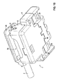
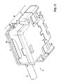
- perspektivische Ansichten schräg von oben eines Adapters in einer zweiten Ausführungsform mit Anschluss-Stecker in Offen- und Kontakt-Position der Adapter-Klapplade,
- Fig. 10 und 11
- perspektivische Ansichten schräg von unten analog
Fig. 8 und9 , - Fig. 12
- eine perspektivische Ansicht des Adapters gemäß
Fig. 9 mit angeschlossenen Krokodilklemmen und gestecktem Mandrin, - Fig. 13 und 14
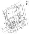
- perspektivische Ansichten schräg von oben eines Adapters in einer weiteren Ausführungsform ohne Auslöseknopf mit Anschluss-Stecker in Offen- und Kontakt-Position der Adapter-Schublade, sowie
- Fig. 15
- eine perspektivische Ansicht eines Adapters in einer weiteren Ausführungsform mit vier Kontaktelementen.
- Die
Fig. 1 bis 7 zeigen eine erste Ausführungsform eines Adapters 1 zum mechanischen und elektrischen Anschluss einer in den Zeichnungen weggeschnitten dargestellten, implantierbaren Elektrode 2 an eine nicht näher dargestellten Messeinrichtung mit Hilfe von Testanschluss-Kontakten, wie sie inFig. 5 und10 in Form von Krokodilklemmen 3, 4 beispielhaft gezeigt sind. Die Elektrode 2 weist dabei an ihrem insbesondere inFig. 1 ,8 und13 erkennbaren proximalen Ende einen Anschluss-Stecker 5 auf, der vier Anschlusskontakte 6.1, 6.2, 6.3 in Form von Ringflächen am Steckerkörper 7 sowie einen Kontakt 6.4 an einem Pin 9 an der Steckerspitze aufweist. Ferner umfasst die Elektrode 2 ein zentrales Lumen 8, das am Ende der Elektrode 2 über den koaxial zur Elektrode 2 verlaufenden Pin 9 herausgeführt ist. - Das Adaptergehäuse 10 weist eine gegliederte Außenform auf, die im groben Umriss als quaderförmig mit einer Länge L, Breite B und Höhe H beschrieben werden kann. Es besteht aus einem elektrisch isolierenden Werkstoff, wie beispielsweise einem spritzgegossenen Kunststoffmaterial.
- Im Adaptergehäuse 10 ist eine Leiterplatte 11 mit zwei Kontaktelementen 12.1, 12.2 in Form von metallischen Kontaktstreifen eingesetzt, von denen in den
Fig. 1 bis 4 und6 die für den Anschluss der Krokodilklemmen 3, 4 dienenden, offen liegende Kontaktflächen 13.1, 13.2 erkennbar sind. Im Verbindungsbereich zum Anschluss-Stecker 5 sind an den Kontaktelementen 12.1, 12.2 jeweils an der Leiterplatte 11 fixierte Federkontakte 14.1, 14.2 elektrisch angeschlossen, die den Kontakt zu den Anschluss-Kontakten 6.3 und 6.4 der Elektrode 2 bei geschlossenem Adapter 1 herstellen (sieheFig. 6 ). Die vom Adaptergehäuse 10 durch die Seitenwangen 15 des Aufbaus 16 und die überstehenden Schmalseiten 17 gebildeten Führungen nehmen das "Maul" 18 der Krokodilklemmen 3, 4 auf (sieheFig. 5 und12 ), wobei die Klemmsicherheit noch durch die Stege 24 an der Unterseite des Adaptergehäuses 10 erhöht wird. - Für den Anschluss-Stecker 5 ist im Adapter 1 eine Aufnahme 19 vorgesehen, die bei der in
Fig. 1 bis 7 gezeigten Ausführungsform in einer Schublade 20 angeordnet ist. Diese Aufnahme 19 entspricht der Form des Anschluss-Steckers 5, so dass dieser lagerichtig und exakt definiert in der Schublade 20 aufgenommen wird, wie diesFig. 1 zeigt. - Die Schublade 20 ist in Richtung der Breite B des Adaptergehäuses 10 zwischen der in
Fig. 1 und3 gezeigten Offen-Position und der inFig. 2 ,4 und5 gezeigten Kontakt-Position lageveränderlich, nämlich über entsprechende Führungen 21 verschiebbar am Adaptergehäuse 10 gelagert. In der Offen-Position gemäßFig. 1 und3 , in der der Anschluss-Stecker 5 in die Aufnahme 19 einsetzbar ist, und in der inFig. 2 und4 gezeigten Kontakt-Position ist die Schublade 20 relativ zum Adaptergehäuse 10 verrastet. Die Verrastung V ist durch eine an der Schublade 20 ausgebildete Rastzunge 33 gebildet, die mit einem Vorsprung 34 in eine Rastausnehmung 35 im Adaptergehäuse 10 vor einem inFig. 1 ,2 ,5 und7 erkennbaren Auslöseknopf 22 eingreift, der über eine elastische Federzunge 23 an das Adaptergehäuse 10 in Richtung der Höhe H verlagerbar angebunden ist. Die Verrastung V ist durch den Auslöseknopf 22 aufhebbar, indem dieser gedrückt und der Vorsprung 34 damit aus der Rastausnehmung 35 gehoben wird. Die Schublade 20 wird damit frei beweglich. - Aus der in
Fig. 1 und3 gezeigten Offen-Position wird die Schublade 20 mit dem eingelegten Anschluss-Stecker 5 quer zu dessen Längsrichtung A in das Adaptergehäuse 10 eingeschoben. In der inFig. 2 ,4 und5 gezeigten Kontakt-Position der Schublade 20 sind dann die beiden Anschlusskontakte 6.3 und 6.4 über die Federkontakte 14.1, 14.2 der Kontaktelemente 12.1, 12.2 elektrisch herausgeführt. Durch die Verrastung der Schublade 20 in dieser Kontakt-Position ist eine sichere Verbindung zwischen dem Anschluss-Stecker 5 und den Kontaktelementen 12.1, 12.2 gegeben. - Auf diese wird, wie
Fig. 5 zeigt, jeweils eine Krokodilklemme 3, 4 aufgeschoben. Deren Sitz auf den Kontaktelementen 12.1, 12.2 wird dabei noch durch die inFig. 3 und4 dargestellten stegförmigen Ausprägungen 24 an der Unterseite des Adaptergehäuses 10 verbessert. Diese Stege sollen das Abrutschen der Krokodilklemmen 3, 4 verhindern. Da die Krokodilklemmen 3, 4 nach außen hin mit ihren Kontakten durch Isolierschuhe 25 abgedeckt sind, ist insgesamt eine saubere, vor Berührungen geschützte Kontaktverbindung zwischen einer Messeinrichtung über die Krokodilklemmen 3, 4 und den Adapter 1 zum Anschluss-Stecker 5 realisiert. - Wie ferner in
Fig. 5 dargestellt ist, weist die Schublade 20 und das Adaptergehäuse 10 eine Öffnung 26 auf, über die der Pin 9 mit dem Lumen 8 der Elektrode 2 auch in der inFig. 2 ,4 und5 gezeigten Kontakt-Position frei zugänglich ist. Somit kann der inFig. 5 eingezeichnete Mandrin 27 durch Ziehen an seinem Handgriff 28 einfach ausgetauscht oder anderweitig betätigt werden, ohne dass sich an der Positionierung des Anschluss-Steckers und Adapters 1 etwas ändern müsste. - In den
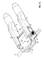
Fig. 8 bis 12 ist eine zweite Ausführungsform des Adapters 1' gezeigt. Diese unterscheidet sich von der Ausführungsform gemäßFig. 1 bis 7 in der Ausführung der Aufnahme-Lade. Diese ist hier durch eine Klapplade 29 realisiert, die am Adaptergehäuse 10 um eine parallel zur Länge verlaufende Schwenkachse S schwenkbar gelagert ist. In der inFig. 8 und10 gezeigten Offen-Position ist die Klapplade 29 hochgeklappt, so dass die Aufnahme 19 von der Seite her für den Anschluss-Stecker 5 der Elektrode 2 zugänglich ist (sieheFig. 8 und10 ). - Durch die Schwenkbewegung um die Schwenkachse S wird der in die Aufnahme 19 eingelegte Anschluss-Stecker 5 in das Adaptergehäuse 10 hineingeschoben und dort intern mit den Kontaktelementen 12.1, 12.2 mechanisch und elektrisch verbunden. Letztere sind analog dem Ausführungsbeispiel gemäß
Fig. 1 bis 7 aufgebaut und bedürfen daher keiner nochmaligen Erörterung. Alle mit dem Adapter 1 gemäßFig. 1 bis 7 übereinstimmenden Komponenten des Adapters 1' sind mit identischen Bezugszeichen versehen, so dass auf die Beschreibung gemäßFig. 1 bis 7 verwiesen werden kann. Zu ergänzen ist, dass die Klapplade 29 in der Offen- und Kontakt-Position gemäßFig. 8 und10 bzw.Fig. 9 ,11 und12 ebenso verrastbar ist. Die Lösung der Verrastung erfolgt durch einfachen Druck oder Zug an der Klapplade 29. Ein Auslöseknopf ist hier nicht vorgesehen. - Wichtig ist zu erwähnen, dass - wie
Fig. 12 zeigt - auch der Adapter 1' so ausgelegt ist, dass über eine Öffnung 26 ein Mandrin 27 über seinen Handgriff 28 während des Anschlusses einer Messeinrichtung durch die Krokodilklemmen 3, 4 in geeigneter Weise manövriert werden kann. - In
Fig. 13 und14 ist eine weitere Ausführungsform eines Adapters 1 " gezeigt, die der Ausführungsform gemäßFig. 1 bis 7 entspricht. Einziger Unterschied ist, dass der Auslöseknopf 22 für die Aufhebung der Verrastung der Schublade 20 in der Offen- und Kontakt-Position weggelassen ist. Diese Verrastungen können - analog dem Ausführungsbeispiel gemäß denFig. 8 bis 12 - durch einfachen Zug oder Druck an der Schublade 20 überwunden werden. - In
Fig. 15 ist schließlich ein Adapter 1 "' gezeigt, der in der grundsätzlichen Ausgestaltung dem Adapter 1 gemäßFig. 1 bis 7 entspricht, allerdings zum Kontaktieren aller vier Anschlusskontakte 6.1 bis 6.4 des Anschluss-Steckers 5 ausgelegt ist. Es sind mit dem Adapter 1 übereinstimmende Komponenten mit identischen Bezugszeichen versehen und bedürfen keiner nochmaligen Erläuterung. Im Unterschied zum vorgenannten Ausführungsbeispiel zeigt die Version des Adapter 1"' gemäßFig. 15 allerdings vier Kontaktelemente 12.1 bis 12.4 auf der Leiterplatte 11 mit entsprechend offen liegenden Kontaktflächen 13.1 bis 13.4, an denen jeweils Krokodilklemmen angesetzt werden können. Die Kontaktelemente 12.1 bis 12.4 auf der Leiterplatte 11 sind im Inneren des Adaptergehäuses 10 wiederum analogFig. 6 an Federkontakten angeschlossen, die mit den einzelnen Anschlusskontakten 6.1 bis 6.4 in der inFig. 15 gezeigten geschlossenen Position des Adapters 1"' elektrisch in Verbindung gebracht werden können. - Allen vier Ausführungsbeispielen des Adapters 1, 1', 1", 1"' ist schließlich gemein, dass das Adaptergehäuse 10 mit Polaritätssymbolen 30, 31 " + " und " - " versehen ist, die den jeweiligen Kontaktflächen 13.1, 13.2 zugeordnet sind. Die Polaritätssymbole 30, 31 sind erhaben auf der Oberseite 32 des Aufbaus 16 der Adaptergehäuse 10 ausgebildet.
Claims (15)
- Adapter zum mechanischen und elektrischen Anschluss einer implantierbaren Elektrode (2) mit ihrem proximalen, mindestens einen Anschluss-Kontakt (6) für eine Elektrodenfläche der Elektrode (2) aufweisenden Anschluss-Stecker (5) an mindestens einen Testanschluss-Kontakt, insbesondere an eine Krokodilklemme (3, 4), einer Messeinrichtung, umfassend- ein Adaptergehäuse (10) aus einem elektrisch isolierenden Werkstoff,- eine an die Form des Anschluss-Steckers (5) angepasste Aufnahme (19) für den Anschluss-Stecker (5),- mindestens ein im Adaptergehäuse (10) angeordnetes Kontaktelement (12) zur Kontaktverbindung zwischen dem mindestens einen Anschluss-Kontakt (6) des Anschluss-Steckers (5) und dem mindestens einen Testanschluss (3, 4), gekennzeichnet durch- eine am Adaptergehäuse (10) zwischen einer Offen-Position und einer geschlossenen Kontakt-Position lageveränderlich gelagerten Aufnahme-Lade (20, 29), in der die Aufnahme (19) für den Anschluss-Stecker (5) angeordnet ist, wobei- in der Offen-Position der Anschluss-Stecker (5) in die Aufnahme (19) in einer definierten Position einsetzbar und wieder daraus entnehmbar ist, und- durch das Überführen der Aufnahme-Lade (20, 29) in die Kontaktposition der mindestens eine Anschluss-Kontakt (6) des Anschluss-Steckers (5) mit dem Kontaktelement (12) im Adaptergehäuse (10) definiert in Kontakt bringbar ist.
- Adapter nach Anspruch 1, dadurch gekennzeichnet, dass die Aufnahme-Lade eine zwischen der Offen- und der Kontakt-Position am Adaptergehäuse (10) verschiebbare Schublade (20) ist.
- Adapter nach Anspruch 2, dadurch gekennzeichnet, dass die Verschieberichtung der Schublade (20) quer zur Längsrichtung (A) des Anschluss-Steckers (5) verläuft.
- Adapter nach Anspruch 1, dadurch gekennzeichnet, dass die Aufnahme-Lade eine zwischen der Offen- und der Kontakt-Position am Adaptergehäuse (10) verschwenkbare Klapplade (29) ist.
- Adapter nach Anspruch 4, dadurch gekennzeichnet, dass die Verschwenkrichtung der Klapplade (29) quer zur Längsrichtung (A) des Anschluss-Steckers (5) verläuft.
- Adapter nach einem der vorgenannten Ansprüche, dadurch gekennzeichnet, dass die Aufnahme-Lade (20, 29) in der Offen- und/oder Kontakt-Position relativ zum Adaptergehäuse (10) durch eine Verrastung (V) festlegbar ist.
- Adapter nach Anspruch 6, dadurch gekennzeichnet, dass die Verrastung (V) durch einen Auslöseknopf (22) lösbar ist.
- Adapter nach Anspruch 7, dadurch gekennzeichnet, dass der Auslöseknopf (22) an das Adaptergehäuse (10) über eine einstückig mit beiden verbundene Federzunge (23) angebunden ist.
- Adapter nach einem der vorgenannten Ansprüche, dadurch gekennzeichnet, dass der mindestens eine Anschluss-Kontakt (6) des Anschluss-Steckers (5) in der Kontaktposition der Aufnahme-Lade (20, 29) nach außen hin vollständig abdeckbar ist.
- Adapter nach einem der vorgenannten Ansprüche, dadurch gekennzeichnet, dass die Aufnahme-Lade (20, 29) und das Adaptergehäuse (10) stirnseitig vor dem in der Aufnahme-Lade (20, 29) positionierbaren Anschluss-Stecker (5) mit einer Öffnung (26) zum freien Zugriff sowohl in der Offen- als auch Kontakt-Position auf ein durch den Anschluss-Stecker (5) geführtes Zentrallumen (8) der Elektrode (2) versehen sind.
- Adapter nach einem der vorgenannten Ansprüche, dadurch gekennzeichnet, dass das mindestens eine Kontaktelement (12) im Adaptergehäuse (10) eine nach außen hin offen liegende Kontaktfläche (13) für den Testanschluss-Kontakt (3, 4) aufweist.
- Adapter nach Anspruch 11, dadurch gekennzeichnet, dass die Kontaktfläche (13) von einer Führung (21) für den Testanschluss-Kontakt (3, 4) flankiert ist.
- Adapter nach einem der vorgenannten Ansprüche, dadurch gekennzeichnet, dass bei einem Adapter für Anschluss-Stecker (5) mit mehreren Anschluss-Kontakten (6.1, 6.2, 6.3, 6.4) die Aufnahme-Lade (20, 29) und das Adaptergehäuse (10) zur elektrischen Verbindung von zwei oder vier Anschluss-Kontakte (6.1, 6.2, 6.3, 6.4) mit zwei Testanschluss-Kontakten (3, 4) über jeweils ein Kontaktelement (12.1, 12.2, 12.3, 12.4) ausgelegt sind.
- Adapter nach Anspruch 13, dadurch gekennzeichnet, dass den Kontaktelementen (12.1, 12.2), insbesondere den offen liegenden Kontaktflächen (13.1, 13.2) der Kontaktelemente (12.1, 12.2) jeweils ein Polaritätssymbol (30, 31) zugeordnet ist.
- Adapter nach einem der vorgenannten Ansprüche, dadurch gekennzeichnet, dass das Adaptergehäuse (10) mehr als vier, vorzugsweise acht Kontaktelemente zum Anschluss von Testanschluss-Kontakten aufweist.
Applications Claiming Priority (1)
| Application Number | Priority Date | Filing Date | Title |
|---|---|---|---|
| US201261660838P | 2012-06-18 | 2012-06-18 |
Publications (2)
| Publication Number | Publication Date |
|---|---|
| EP2676698A1 true EP2676698A1 (de) | 2013-12-25 |
| EP2676698B1 EP2676698B1 (de) | 2014-09-03 |
Family
ID=48444208
Family Applications (1)
| Application Number | Title | Priority Date | Filing Date |
|---|---|---|---|
| EP13168212.2A Not-in-force EP2676698B1 (de) | 2012-06-18 | 2013-05-17 | Adapter zum mechanischen und elektrischen Anschluss einer implantierbaren Elektrode an mindestens einen Testanschluss-Kontakt |
Country Status (3)
| Country | Link |
|---|---|
| US (1) | US9059548B2 (de) |
| EP (1) | EP2676698B1 (de) |
| CN (1) | CN103515760B (de) |
Cited By (1)
| Publication number | Priority date | Publication date | Assignee | Title |
|---|---|---|---|---|
| US11944828B2 (en) | 2020-09-24 | 2024-04-02 | Medtronic, Inc. | Rotatable adapter for connecting implantable medical leads to test devices |
Families Citing this family (8)
| Publication number | Priority date | Publication date | Assignee | Title |
|---|---|---|---|---|
| FR3040553B1 (fr) * | 2015-08-31 | 2022-08-12 | Delphi Int Operations Luxembourg Sarl | Connecteur pour vehicules automobiles et procede de montage d'un tel connecteur |
| WO2018170358A1 (en) * | 2017-03-16 | 2018-09-20 | Medtronic, Inc. | Adapter assemblies for implantable medical electrical systems |
| US10992078B2 (en) | 2018-01-29 | 2021-04-27 | Bard Access Systems, Inc. | Connection system for establishing an electrical connection through a drape and methods thereof |
| WO2019221926A1 (en) | 2018-05-18 | 2019-11-21 | Bard Access Systems, Inc. | Connection systems and methods thereof for establishing an electrical connection through a drape |
| WO2021021408A1 (en) | 2019-07-29 | 2021-02-04 | Bard Access Systems, Inc. | Connection systems and methods for establishing optical and electrical connections through a drape |
| CN112336338A (zh) | 2019-08-08 | 2021-02-09 | 巴德阿克塞斯系统股份有限公司 | 包括光纤连接器模块的形状感测系统及其方法 |
| US12690935B2 (en) | 2020-10-13 | 2026-07-28 | Bard Access Systems, Inc. | Portal-establishing devices and methods thereof for establishing portals in procedural barriers |
| WO2022093991A1 (en) | 2020-10-28 | 2022-05-05 | Bard Access Systems, Inc. | Systems and methods including procedural barrier-breaching connectors and connection-establishing devices |
Citations (8)
| Publication number | Priority date | Publication date | Assignee | Title |
|---|---|---|---|---|
| US5354326A (en) | 1993-01-27 | 1994-10-11 | Medtronic, Inc. | Screening cable connector for interface to implanted lead |
| US20020095079A1 (en) * | 2000-04-19 | 2002-07-18 | Putz David A. | Electrical connector for multi-contact medical electrodes |
| US20050177199A1 (en) * | 2004-02-09 | 2005-08-11 | Cardiac Pacemakers, Inc. | PSA cable and connector for quadripolar lead terminal |
| US20060030918A1 (en) * | 2004-08-04 | 2006-02-09 | Chinn Kenny K | Operating room lead connector |
| US20060258193A1 (en) * | 2005-05-12 | 2006-11-16 | Cardiac Pacemakers, Inc. | Lead terminal multi-tool |
| US20080015668A1 (en) * | 2004-02-23 | 2008-01-17 | Soukup Thomas M | Test Connector for Implantable Leads |
| US7777140B2 (en) | 2005-10-07 | 2010-08-17 | Pacesetter, Inc. | IS-4 lead to PSA interface cable |
| US20120130397A1 (en) * | 2010-11-19 | 2012-05-24 | Reddy G Shantanu | Multi-function lead implant tool |
Family Cites Families (5)
| Publication number | Priority date | Publication date | Assignee | Title |
|---|---|---|---|---|
| NL142535B (nl) * | 1965-01-08 | 1974-06-17 | Electro Oceanics | Waterdicht uitgevoerde losneembare steekverbinding. |
| JP5152310B2 (ja) * | 2010-12-03 | 2013-02-27 | 株式会社デンソー | 組電池の電圧検出装置 |
| US8147275B1 (en) * | 2011-01-27 | 2012-04-03 | Medtronic, Inc. | Interface adapters for implantable medical electrical leads having a sidewall with an opening with a canted edge |
| CN102255183B (zh) * | 2011-04-20 | 2014-06-18 | 北京品驰医疗设备有限公司 | 一种植入式神经刺激系统的延长导线 |
| US8480427B2 (en) * | 2011-07-20 | 2013-07-09 | Bpm Medical, Llc | Cable connector |
-
2013
- 2013-05-17 EP EP13168212.2A patent/EP2676698B1/de not_active Not-in-force
- 2013-06-05 CN CN201310219442.0A patent/CN103515760B/zh not_active Expired - Fee Related
- 2013-06-06 US US13/911,709 patent/US9059548B2/en not_active Expired - Fee Related
Patent Citations (9)
| Publication number | Priority date | Publication date | Assignee | Title |
|---|---|---|---|---|
| US5354326A (en) | 1993-01-27 | 1994-10-11 | Medtronic, Inc. | Screening cable connector for interface to implanted lead |
| US20020095079A1 (en) * | 2000-04-19 | 2002-07-18 | Putz David A. | Electrical connector for multi-contact medical electrodes |
| US20050177199A1 (en) * | 2004-02-09 | 2005-08-11 | Cardiac Pacemakers, Inc. | PSA cable and connector for quadripolar lead terminal |
| US20080015668A1 (en) * | 2004-02-23 | 2008-01-17 | Soukup Thomas M | Test Connector for Implantable Leads |
| US20060030918A1 (en) * | 2004-08-04 | 2006-02-09 | Chinn Kenny K | Operating room lead connector |
| US20060258193A1 (en) * | 2005-05-12 | 2006-11-16 | Cardiac Pacemakers, Inc. | Lead terminal multi-tool |
| US7753696B2 (en) | 2005-05-12 | 2010-07-13 | Cardiac Pacemakers, Inc. | Lead terminal multi-tool |
| US7777140B2 (en) | 2005-10-07 | 2010-08-17 | Pacesetter, Inc. | IS-4 lead to PSA interface cable |
| US20120130397A1 (en) * | 2010-11-19 | 2012-05-24 | Reddy G Shantanu | Multi-function lead implant tool |
Cited By (2)
| Publication number | Priority date | Publication date | Assignee | Title |
|---|---|---|---|---|
| US11944828B2 (en) | 2020-09-24 | 2024-04-02 | Medtronic, Inc. | Rotatable adapter for connecting implantable medical leads to test devices |
| US12447351B2 (en) | 2020-09-24 | 2025-10-21 | Medtronic, Inc. | Rotatable adapter for connecting implantable medical leads to test devices |
Also Published As
| Publication number | Publication date |
|---|---|
| CN103515760B (zh) | 2017-06-09 |
| US9059548B2 (en) | 2015-06-16 |
| CN103515760A (zh) | 2014-01-15 |
| US20130337674A1 (en) | 2013-12-19 |
| EP2676698B1 (de) | 2014-09-03 |
Similar Documents
| Publication | Publication Date | Title |
|---|---|---|
| EP2676698B1 (de) | Adapter zum mechanischen und elektrischen Anschluss einer implantierbaren Elektrode an mindestens einen Testanschluss-Kontakt | |
| DE19818505A1 (de) | Medizinischer Leitungsadapter, Verfahren zum Herstellen desselben sowie zum Herstellen einer schnellen elektrischen Verbindung | |
| DE2644560C2 (de) | Vorrichtung zum Ergreifen eines flachen, rechteckigen, elektrischen Bauelements | |
| DE102007059096B4 (de) | Elektrodenklemme zum elektrischen Kontaktieren einer Filmelektrode und einer Druckknopfelektrode | |
| DE102016204743A1 (de) | Steckverbinder mit Kurzschlusselement | |
| EP2721692A1 (de) | Elektrisches verbindungsmodul | |
| EP2683036B1 (de) | Steckgehäuse zum zumindest teilweisen Aufnehmen eines Gehäuseeinsteckbauteils und elektrische Steckverbindungsanordnung zum Miteinander-Verbinden eines männlichen Kontaktelements und eines weiblichen Kontaktelements | |
| DE102021109565A1 (de) | Klemmfederkontakteinrichtung mit Überdehnschutz und Steckverbindereinsatz mit mindestens einer solchen Klemmfederkontakteinrichtung | |
| EP1061995B1 (de) | Testkabelanordnung | |
| EP3630266A1 (de) | Elektromedizinischer adapter, elektromedizinische elektrode und elektromedizinischer impulsgeber | |
| EP2110156B1 (de) | Feldentkopplungs-Element zur Verwendung mit einer implantierbaren Leitung und implantierbares medizinisches Gerät | |
| EP1714672B1 (de) | Kontaktverbindungs-Adapter zur Herstellung eines zeitweisen elektrischen Kontaktes zwischen zwei Steckern | |
| DE102014014999B4 (de) | Externer Herzschrittmacher/Kardioverter | |
| DE102013001021B4 (de) | Externer Herzschrittmacher mit einer über einen Steckverbinder angeschlossenen, temporär mit einem Herzen verbindbaren Elektrode | |
| DE102017212943A1 (de) | Verbinder | |
| DE3839011C2 (de) | Steckerbrücke für einen elektrischen Gerätestecker mit mindestens einem Phasen- und einem Nulleiterstift | |
| DE102020124427B4 (de) | Medizinisches hf-instrument | |
| DE102015004328B4 (de) | Transporteur und Stecker eines Resektoskopes | |
| DE2123568A1 (de) | Elektrische Steckverbindung | |
| EP0332035A2 (de) | Elektrischer Gerätestecker mit einer Halteplatte für die Kontaktfedern | |
| DE4336189C2 (de) | Geräteanschlußklemme | |
| DE2949314C2 (de) | Kabelklemmvorrichtung aus Kunststoff mit Zugentlastung, insbesondere für elektrische Steckverbinder, für eine Mehrzahl von Einzeldrähten im elektronischen Schaltungsbau | |
| WO2017140727A1 (de) | Chirurgiegeräte-mehrfachbuchse, elektrochirurgie-hochfrequenzgenerator, elektrochirurgiegerätestecker und elektrochirurgisches system | |
| WO2016142286A1 (de) | Mehrfachstecker auf schiene | |
| DE69932278T2 (de) | Verbindungs-/Trenn- modul für elektrische isolierte Leiterpaare |
Legal Events
| Date | Code | Title | Description |
|---|---|---|---|
| PUAI | Public reference made under article 153(3) epc to a published international application that has entered the european phase |
Free format text: ORIGINAL CODE: 0009012 |
|
| AK | Designated contracting states |
Kind code of ref document: A1 Designated state(s): AL AT BE BG CH CY CZ DE DK EE ES FI FR GB GR HR HU IE IS IT LI LT LU LV MC MK MT NL NO PL PT RO RS SE SI SK SM TR |
|
| AX | Request for extension of the european patent |
Extension state: BA ME |
|
| 17P | Request for examination filed |
Effective date: 20131212 |
|
| RBV | Designated contracting states (corrected) |
Designated state(s): AL AT BE BG CH CY CZ DE DK EE ES FI FR GB GR HR HU IE IS IT LI LT LU LV MC MK MT NL NO PL PT RO RS SE SI SK SM TR |
|
| GRAP | Despatch of communication of intention to grant a patent |
Free format text: ORIGINAL CODE: EPIDOSNIGR1 |
|
| RIC1 | Information provided on ipc code assigned before grant |
Ipc: H01R 13/62 20060101ALI20140506BHEP Ipc: A61N 1/375 20060101AFI20140506BHEP Ipc: A61N 1/372 20060101ALI20140506BHEP Ipc: H01R 24/28 20110101ALI20140506BHEP |
|
| INTG | Intention to grant announced |
Effective date: 20140521 |
|
| GRAS | Grant fee paid |
Free format text: ORIGINAL CODE: EPIDOSNIGR3 |
|
| GRAP | Despatch of communication of intention to grant a patent |
Free format text: ORIGINAL CODE: EPIDOSNIGR1 |
|
| GRAA | (expected) grant |
Free format text: ORIGINAL CODE: 0009210 |
|
| INTG | Intention to grant announced |
Effective date: 20140724 |
|
| AK | Designated contracting states |
Kind code of ref document: B1 Designated state(s): AL AT BE BG CH CY CZ DE DK EE ES FI FR GB GR HR HU IE IS IT LI LT LU LV MC MK MT NL NO PL PT RO RS SE SI SK SM TR |
|
| REG | Reference to a national code |
Ref country code: GB Ref legal event code: FG4D Free format text: NOT ENGLISH |
|
| REG | Reference to a national code |
Ref country code: CH Ref legal event code: EP Ref country code: AT Ref legal event code: REF Ref document number: 685235 Country of ref document: AT Kind code of ref document: T Effective date: 20140915 |
|
| REG | Reference to a national code |
Ref country code: IE Ref legal event code: FG4D Free format text: LANGUAGE OF EP DOCUMENT: GERMAN |
|
| REG | Reference to a national code |
Ref country code: DE Ref legal event code: R096 Ref document number: 502013000090 Country of ref document: DE Effective date: 20141016 |
|
| PG25 | Lapsed in a contracting state [announced via postgrant information from national office to epo] |
Ref country code: FI Free format text: LAPSE BECAUSE OF FAILURE TO SUBMIT A TRANSLATION OF THE DESCRIPTION OR TO PAY THE FEE WITHIN THE PRESCRIBED TIME-LIMIT Effective date: 20140903 Ref country code: SE Free format text: LAPSE BECAUSE OF FAILURE TO SUBMIT A TRANSLATION OF THE DESCRIPTION OR TO PAY THE FEE WITHIN THE PRESCRIBED TIME-LIMIT Effective date: 20140903 Ref country code: GR Free format text: LAPSE BECAUSE OF FAILURE TO SUBMIT A TRANSLATION OF THE DESCRIPTION OR TO PAY THE FEE WITHIN THE PRESCRIBED TIME-LIMIT Effective date: 20141204 Ref country code: NO Free format text: LAPSE BECAUSE OF FAILURE TO SUBMIT A TRANSLATION OF THE DESCRIPTION OR TO PAY THE FEE WITHIN THE PRESCRIBED TIME-LIMIT Effective date: 20141203 Ref country code: ES Free format text: LAPSE BECAUSE OF FAILURE TO SUBMIT A TRANSLATION OF THE DESCRIPTION OR TO PAY THE FEE WITHIN THE PRESCRIBED TIME-LIMIT Effective date: 20140903 Ref country code: LT Free format text: LAPSE BECAUSE OF FAILURE TO SUBMIT A TRANSLATION OF THE DESCRIPTION OR TO PAY THE FEE WITHIN THE PRESCRIBED TIME-LIMIT Effective date: 20140903 |
|
| REG | Reference to a national code |
Ref country code: NL Ref legal event code: VDEP Effective date: 20140903 |
|
| REG | Reference to a national code |
Ref country code: LT Ref legal event code: MG4D |
|
| PG25 | Lapsed in a contracting state [announced via postgrant information from national office to epo] |
Ref country code: CY Free format text: LAPSE BECAUSE OF FAILURE TO SUBMIT A TRANSLATION OF THE DESCRIPTION OR TO PAY THE FEE WITHIN THE PRESCRIBED TIME-LIMIT Effective date: 20140903 Ref country code: RS Free format text: LAPSE BECAUSE OF FAILURE TO SUBMIT A TRANSLATION OF THE DESCRIPTION OR TO PAY THE FEE WITHIN THE PRESCRIBED TIME-LIMIT Effective date: 20140903 Ref country code: LV Free format text: LAPSE BECAUSE OF FAILURE TO SUBMIT A TRANSLATION OF THE DESCRIPTION OR TO PAY THE FEE WITHIN THE PRESCRIBED TIME-LIMIT Effective date: 20140903 Ref country code: HR Free format text: LAPSE BECAUSE OF FAILURE TO SUBMIT A TRANSLATION OF THE DESCRIPTION OR TO PAY THE FEE WITHIN THE PRESCRIBED TIME-LIMIT Effective date: 20140903 |
|
| PG25 | Lapsed in a contracting state [announced via postgrant information from national office to epo] |
Ref country code: NL Free format text: LAPSE BECAUSE OF FAILURE TO SUBMIT A TRANSLATION OF THE DESCRIPTION OR TO PAY THE FEE WITHIN THE PRESCRIBED TIME-LIMIT Effective date: 20140903 |
|
| PG25 | Lapsed in a contracting state [announced via postgrant information from national office to epo] |
Ref country code: SK Free format text: LAPSE BECAUSE OF FAILURE TO SUBMIT A TRANSLATION OF THE DESCRIPTION OR TO PAY THE FEE WITHIN THE PRESCRIBED TIME-LIMIT Effective date: 20140903 Ref country code: CZ Free format text: LAPSE BECAUSE OF FAILURE TO SUBMIT A TRANSLATION OF THE DESCRIPTION OR TO PAY THE FEE WITHIN THE PRESCRIBED TIME-LIMIT Effective date: 20140903 Ref country code: PT Free format text: LAPSE BECAUSE OF FAILURE TO SUBMIT A TRANSLATION OF THE DESCRIPTION OR TO PAY THE FEE WITHIN THE PRESCRIBED TIME-LIMIT Effective date: 20150105 Ref country code: EE Free format text: LAPSE BECAUSE OF FAILURE TO SUBMIT A TRANSLATION OF THE DESCRIPTION OR TO PAY THE FEE WITHIN THE PRESCRIBED TIME-LIMIT Effective date: 20140903 Ref country code: IS Free format text: LAPSE BECAUSE OF FAILURE TO SUBMIT A TRANSLATION OF THE DESCRIPTION OR TO PAY THE FEE WITHIN THE PRESCRIBED TIME-LIMIT Effective date: 20150103 Ref country code: RO Free format text: LAPSE BECAUSE OF FAILURE TO SUBMIT A TRANSLATION OF THE DESCRIPTION OR TO PAY THE FEE WITHIN THE PRESCRIBED TIME-LIMIT Effective date: 20140903 |
|
| PG25 | Lapsed in a contracting state [announced via postgrant information from national office to epo] |
Ref country code: PL Free format text: LAPSE BECAUSE OF FAILURE TO SUBMIT A TRANSLATION OF THE DESCRIPTION OR TO PAY THE FEE WITHIN THE PRESCRIBED TIME-LIMIT Effective date: 20140903 |
|
| REG | Reference to a national code |
Ref country code: DE Ref legal event code: R097 Ref document number: 502013000090 Country of ref document: DE |
|
| REG | Reference to a national code |
Ref country code: DE Ref legal event code: R082 Ref document number: 502013000090 Country of ref document: DE Representative=s name: RANDOLL, SOEREN, DIPL.-CHEM. UNIV. DR. RER. NA, DE |
|
| PLBE | No opposition filed within time limit |
Free format text: ORIGINAL CODE: 0009261 |
|
| STAA | Information on the status of an ep patent application or granted ep patent |
Free format text: STATUS: NO OPPOSITION FILED WITHIN TIME LIMIT |
|
| PG25 | Lapsed in a contracting state [announced via postgrant information from national office to epo] |
Ref country code: DK Free format text: LAPSE BECAUSE OF FAILURE TO SUBMIT A TRANSLATION OF THE DESCRIPTION OR TO PAY THE FEE WITHIN THE PRESCRIBED TIME-LIMIT Effective date: 20140903 |
|
| 26N | No opposition filed |
Effective date: 20150604 |
|
| PG25 | Lapsed in a contracting state [announced via postgrant information from national office to epo] |
Ref country code: IT Free format text: LAPSE BECAUSE OF FAILURE TO SUBMIT A TRANSLATION OF THE DESCRIPTION OR TO PAY THE FEE WITHIN THE PRESCRIBED TIME-LIMIT Effective date: 20140903 |
|
| PG25 | Lapsed in a contracting state [announced via postgrant information from national office to epo] |
Ref country code: SI Free format text: LAPSE BECAUSE OF FAILURE TO SUBMIT A TRANSLATION OF THE DESCRIPTION OR TO PAY THE FEE WITHIN THE PRESCRIBED TIME-LIMIT Effective date: 20140903 |
|
| PG25 | Lapsed in a contracting state [announced via postgrant information from national office to epo] |
Ref country code: LU Free format text: LAPSE BECAUSE OF FAILURE TO SUBMIT A TRANSLATION OF THE DESCRIPTION OR TO PAY THE FEE WITHIN THE PRESCRIBED TIME-LIMIT Effective date: 20150517 Ref country code: MC Free format text: LAPSE BECAUSE OF FAILURE TO SUBMIT A TRANSLATION OF THE DESCRIPTION OR TO PAY THE FEE WITHIN THE PRESCRIBED TIME-LIMIT Effective date: 20140903 |
|
| REG | Reference to a national code |
Ref country code: FR Ref legal event code: ST Effective date: 20160129 |
|
| PG25 | Lapsed in a contracting state [announced via postgrant information from national office to epo] |
Ref country code: FR Free format text: LAPSE BECAUSE OF NON-PAYMENT OF DUE FEES Effective date: 20150601 |
|
| PG25 | Lapsed in a contracting state [announced via postgrant information from national office to epo] |
Ref country code: MT Free format text: LAPSE BECAUSE OF FAILURE TO SUBMIT A TRANSLATION OF THE DESCRIPTION OR TO PAY THE FEE WITHIN THE PRESCRIBED TIME-LIMIT Effective date: 20140903 |
|
| PG25 | Lapsed in a contracting state [announced via postgrant information from national office to epo] |
Ref country code: HU Free format text: LAPSE BECAUSE OF FAILURE TO SUBMIT A TRANSLATION OF THE DESCRIPTION OR TO PAY THE FEE WITHIN THE PRESCRIBED TIME-LIMIT; INVALID AB INITIO Effective date: 20130517 Ref country code: BG Free format text: LAPSE BECAUSE OF FAILURE TO SUBMIT A TRANSLATION OF THE DESCRIPTION OR TO PAY THE FEE WITHIN THE PRESCRIBED TIME-LIMIT Effective date: 20140903 |
|
| PG25 | Lapsed in a contracting state [announced via postgrant information from national office to epo] |
Ref country code: BE Free format text: LAPSE BECAUSE OF NON-PAYMENT OF DUE FEES Effective date: 20150531 |
|
| PG25 | Lapsed in a contracting state [announced via postgrant information from national office to epo] |
Ref country code: TR Free format text: LAPSE BECAUSE OF FAILURE TO SUBMIT A TRANSLATION OF THE DESCRIPTION OR TO PAY THE FEE WITHIN THE PRESCRIBED TIME-LIMIT Effective date: 20140903 |
|
| GBPC | Gb: european patent ceased through non-payment of renewal fee |
Effective date: 20170517 |
|
| PG25 | Lapsed in a contracting state [announced via postgrant information from national office to epo] |
Ref country code: GB Free format text: LAPSE BECAUSE OF NON-PAYMENT OF DUE FEES Effective date: 20170517 |
|
| PG25 | Lapsed in a contracting state [announced via postgrant information from national office to epo] |
Ref country code: SM Free format text: LAPSE BECAUSE OF FAILURE TO SUBMIT A TRANSLATION OF THE DESCRIPTION OR TO PAY THE FEE WITHIN THE PRESCRIBED TIME-LIMIT Effective date: 20140903 |
|
| PG25 | Lapsed in a contracting state [announced via postgrant information from national office to epo] |
Ref country code: MK Free format text: LAPSE BECAUSE OF FAILURE TO SUBMIT A TRANSLATION OF THE DESCRIPTION OR TO PAY THE FEE WITHIN THE PRESCRIBED TIME-LIMIT Effective date: 20140903 |
|
| PG25 | Lapsed in a contracting state [announced via postgrant information from national office to epo] |
Ref country code: AL Free format text: LAPSE BECAUSE OF FAILURE TO SUBMIT A TRANSLATION OF THE DESCRIPTION OR TO PAY THE FEE WITHIN THE PRESCRIBED TIME-LIMIT Effective date: 20140903 |
|
| REG | Reference to a national code |
Ref country code: AT Ref legal event code: MM01 Ref document number: 685235 Country of ref document: AT Kind code of ref document: T Effective date: 20180517 |
|
| PG25 | Lapsed in a contracting state [announced via postgrant information from national office to epo] |
Ref country code: AT Free format text: LAPSE BECAUSE OF NON-PAYMENT OF DUE FEES Effective date: 20180517 |
|
| PGFP | Annual fee paid to national office [announced via postgrant information from national office to epo] |
Ref country code: DE Payment date: 20210526 Year of fee payment: 9 |
|
| PGFP | Annual fee paid to national office [announced via postgrant information from national office to epo] |
Ref country code: IE Payment date: 20210519 Year of fee payment: 9 Ref country code: CH Payment date: 20210525 Year of fee payment: 9 |
|
| REG | Reference to a national code |
Ref country code: DE Ref legal event code: R119 Ref document number: 502013000090 Country of ref document: DE |
|
| REG | Reference to a national code |
Ref country code: CH Ref legal event code: PL |
|
| PG25 | Lapsed in a contracting state [announced via postgrant information from national office to epo] |
Ref country code: LI Free format text: LAPSE BECAUSE OF NON-PAYMENT OF DUE FEES Effective date: 20220531 Ref country code: CH Free format text: LAPSE BECAUSE OF NON-PAYMENT OF DUE FEES Effective date: 20220531 |
|
| PG25 | Lapsed in a contracting state [announced via postgrant information from national office to epo] |
Ref country code: IE Free format text: LAPSE BECAUSE OF NON-PAYMENT OF DUE FEES Effective date: 20220517 |
|
| PG25 | Lapsed in a contracting state [announced via postgrant information from national office to epo] |
Ref country code: DE Free format text: LAPSE BECAUSE OF NON-PAYMENT OF DUE FEES Effective date: 20221201 |