EP2676321B1 - Coupling arrangement - Google Patents
Coupling arrangement Download PDFInfo
- Publication number
- EP2676321B1 EP2676321B1 EP11867472.0A EP11867472A EP2676321B1 EP 2676321 B1 EP2676321 B1 EP 2676321B1 EP 11867472 A EP11867472 A EP 11867472A EP 2676321 B1 EP2676321 B1 EP 2676321B1
- Authority
- EP
- European Patent Office
- Prior art keywords
- module
- slot
- substrate
- motherboard
- conductor
- Prior art date
- Legal status (The legal status is an assumption and is not a legal conclusion. Google has not performed a legal analysis and makes no representation as to the accuracy of the status listed.)
- Active
Links
- 230000008878 coupling Effects 0.000 title claims description 48
- 238000010168 coupling process Methods 0.000 title claims description 48
- 238000005859 coupling reaction Methods 0.000 title claims description 48
- 239000000758 substrate Substances 0.000 claims description 54
- 239000004020 conductor Substances 0.000 claims description 39
- 239000000126 substance Substances 0.000 claims description 16
- 239000003989 dielectric material Substances 0.000 claims description 14
- 229910000679 solder Inorganic materials 0.000 claims description 7
- 239000000853 adhesive Substances 0.000 claims description 2
- 230000001070 adhesive effect Effects 0.000 claims description 2
- 238000005516 engineering process Methods 0.000 description 6
- 238000004519 manufacturing process Methods 0.000 description 4
- 239000002184 metal Substances 0.000 description 3
- 238000000034 method Methods 0.000 description 3
- 238000007639 printing Methods 0.000 description 3
- 241000761557 Lamina Species 0.000 description 2
- 230000003321 amplification Effects 0.000 description 2
- 239000011888 foil Substances 0.000 description 2
- 238000003199 nucleic acid amplification method Methods 0.000 description 2
- 230000004044 response Effects 0.000 description 2
- 239000000523 sample Substances 0.000 description 2
- 230000006978 adaptation Effects 0.000 description 1
- 239000000919 ceramic Substances 0.000 description 1
- 230000008602 contraction Effects 0.000 description 1
- 230000002542 deteriorative effect Effects 0.000 description 1
- 238000007747 plating Methods 0.000 description 1
- 230000008569 process Effects 0.000 description 1
- 230000009467 reduction Effects 0.000 description 1
- 230000008439 repair process Effects 0.000 description 1
- 238000007650 screen-printing Methods 0.000 description 1
- 230000008054 signal transmission Effects 0.000 description 1
- 230000007704 transition Effects 0.000 description 1
Images


Classifications
-
- H—ELECTRICITY
- H01—ELECTRIC ELEMENTS
- H01P—WAVEGUIDES; RESONATORS, LINES, OR OTHER DEVICES OF THE WAVEGUIDE TYPE
- H01P5/00—Coupling devices of the waveguide type
- H01P5/08—Coupling devices of the waveguide type for linking dissimilar lines or devices
- H01P5/10—Coupling devices of the waveguide type for linking dissimilar lines or devices for coupling balanced with unbalanced lines or devices
- H01P5/107—Hollow-waveguide/strip-line transitions
-
- H—ELECTRICITY
- H01—ELECTRIC ELEMENTS
- H01P—WAVEGUIDES; RESONATORS, LINES, OR OTHER DEVICES OF THE WAVEGUIDE TYPE
- H01P5/00—Coupling devices of the waveguide type
- H01P5/08—Coupling devices of the waveguide type for linking dissimilar lines or devices
-
- H—ELECTRICITY
- H01—ELECTRIC ELEMENTS
- H01P—WAVEGUIDES; RESONATORS, LINES, OR OTHER DEVICES OF THE WAVEGUIDE TYPE
- H01P5/00—Coupling devices of the waveguide type
- H01P5/02—Coupling devices of the waveguide type with invariable factor of coupling
- H01P5/022—Transitions between lines of the same kind and shape, but with different dimensions
- H01P5/028—Transitions between lines of the same kind and shape, but with different dimensions between strip lines
Description
- The invention relates to a coupling arrangement for a transfer of a microwave signal between a motherboard and a module.
- To produce fully industrial high frequency microwave radio systems, it is a must to make them in a Surface Mount (SMT)- process. This is due to several reasons:
- To have as low "built-up-value" components in the final manufacturing as possible, in order to reduce cost,
- To lift out chip-attach technologies and wire-bonding from "in-house-manufacturing" at radio-manufacturers, since such technologies tend to be hard to automate, which also drives cost.
- There are many different types of modules for microwave radio system that may be desired to be connected to a motherboard. One example is a package which may contain some kind of microwave electronics such as a filter or a microwave integrated circuit. Another type of module may be a smaller (sub-)board carrying several electrical components. All such modules, however, have in common that they must be connected to the main motherboard in such a way that microwave signals can be exchanged between them in an efficient way.
- In the prior art surface mounted (SMT) microwave signal systems, the transferring of signals between a motherboard and a module, for instance a surface mounted package, is mostly based on connections from a microstrip to a Coplanar Waveguide to a microstrip. They work well up to around 40-50 GHz and with some limitations up to 60 GHz.
- For microwave radios and automotive radar around 75 - 85 GHz and above another approach, Chip On Board (COB) solutions mostly is used, i.e. the chip is directly mounted on and electrically interconnected to its final circuit board, instead of first being incorporated in a package that then can be mounted on a desired board. However, the chip on board model means higher technology in the end manufacturing and such solutions are also harder and more expensive to repair.
- Such Chip On Board concepts allow full Surface Mount (SMT)-manufacturing of products that can transfer microwave signals with a frequency of up to around 120 GHz.
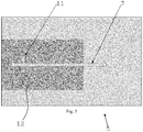
- The prior art surface mounted module systems, mentioned above, will now be described a bit more with reference to
figs. 1 and 2 . They are based on a microstrip at the motherboard and also inside the package and an inter-connection by a Coplanar Waveguide-system. In this way, the lower microstrip is lifted up to a higher microstrip. This concept gives losses and limitations when signal frequencies are passing somewhere around 40 GHz. - Such a prior
art coupling arrangement 1 is shown infig. 1 . It discloses amotherboard 2 comprising asubstrate 3 and amicrostrip 4. Themotherboard 2 is connected to asurface mount module 5, said module comprising asubstrate 6 and amicrostrip conductor 7. Theconnection 17 between themotherboard 2 and themodule 5 is shown encircled with an oval in the figure. A via-hole 18 is shown interconnecting an underside with an upper side of thesubstrate 6 of themodule 5. Infig. 1 , X-X denotes a cross section through theconnection 17; this cross section is detailed infig. 2 . - The cross section X-X of the connection between the motherboard and the module can be studied further in
fig. 2 . Themotherboard 2 is connected to themodule 5 via acoplanar waveguide 20. Thecoplanar waveguide 20 comprises twoground conductors 21 each comprising a solder pad on each of the motherboard and the module with solder in between. The ground can be seen transported from themotherboard ground plane 19 through the motherboard, by way ofvias 22, to the upper side of the motherboard. Thecoplanar waveguide 20 further comprises, in the same plane as theground conductors 21, asignal conductor 23 comprising the microstrip on the motherboard connected with solder to a via-hole 18 leading up to themicrostrip 7 on the upper side of themodule 5. - This prior art arrangement is straightforward, however the transmission of signals from microstrip to Coplanar Waveguide to microstrip is hard to maintain with a "smooth" flow at higher frequencies, which results in losses.
- Tze-Min Shen, Ting-Yi Huang, Chi-Feng Chen, Ruey-Beei Wu: "A Laminated Waveguide Magic-T With Bandpass Filter Response in Multilayer LTCC", IEEE TRANSACTIONS ON MICROWAVE THEORY AND TECHNIQUES, Vol. 59, No. 3, p. 584-592, March 2011, is related to a laminated waveguide magic-T with imbedded Chebyshev filter response in a multilayer low-temperature co-fired ceramic technology by vertically stacked rectangular cavity resonators with highly symmetric coupling structures. The cavities are fed by microstrip lines through slots etched on outer metal layers. Internal couplings between the cavities are realized by slots on a common broad wall between adjacent cavities.
- Tze-Min Shen et al. do not disclose a slot coupling comprising two slots which are connected by a connecting substance around their peripheries.
-
US 5821836 A relates to miniaturized or micromachined circuits, and more specifically to filters and multiplexers that provide improved performance for high frequency applications. -
WO 2011/030277 A2 relates to a system for injecting and guiding millimeter- waves through a Printed Circuit Board (PCB), the system including at least two laminas belonging to a PCB. An electrically conductive plating is applied on the insulating walls of a cavity formed perpendicularly through the laminas. Optionally, a probe located above the cavity is printed on a lamina belonging to the PCB. In one embodiment, the cavity guides millimeter-waves injected by the probe at one side of the cavity to the other side of the cavity. - Hanna Yousef, Shi Cheng, Hanrik Kratz: "Substrate Integrated Waveguides (SIWs) in a Flexible Printed circuit Board for Millimeter-Wave Applications", JOURNAL OF MICROELECTROMECHANICAL SYSTEMS, Vol. 18, No. 1, p. 154-162, February 2009, relates to SIWs in a flexible PCB for application in the 77-81 GHz range. Vertical walls of the SIWs consist of multiple electrodeposited metallic wires, diameters of these wires and the spacing between them being on the order of hundreds of nanometers.
-
US 6437669 B1 relates generally to microwave and millimeter wave substrate technology and, more particularly, to a method for forming microwave and millimeter wave frequency solder connections to a substrate. - It is an object of the present invention to propose a solution for or a reduction of the problems of prior art. A main object is consequently to provide a coupling arrangement for a surface mounted device module that is suitable for transfer of signals with a high frequency.
- This object is attained with a slot-feed technology for input/output transmit signals to/from the module from/to the motherboard. This will give less loss than existing systems.
- The
coupling arrangement 1, for transfer of a microwave signal, according to the invention comprises: - a
motherboard 2 comprising asubstrate 3 with amicrostrip conductor 4, and - a
module 5 comprising asubstrate 6 with amicrostrip conductor 7, - a substrate integrated
waveguide 8 formed in thesubstrate 3 of themotherboard 2, and - a
slot coupling 9;
wherein themodule 5 is attached to themotherboard 2 such that themotherboard conductor 4, by means of aconnection 17, is in electrical contact with themodule conductor 7, whereby the microwave signal may be transferred between themotherboard conductor 4 and themodule conductor 7;
wherein theconnection 17 comprises- the substrate integrated
waveguide 8, - the
slot coupling 9, - the
module conductor 7, and - the
motherboard conductor 4 connected to the substrate integratedwaveguide 8, which substrate integratedwaveguide 8 is connected to themodule conductor 7 via theslot coupling 9;
slot coupling 9 comprises- a
slot 11 in aground plane 12 on a side of themodule substrate 6, - a
slot 10 in the substrate integratedwaveguide 8 connected to theslot 11 in theground plane 12 on the side of themodule substrate 6, and - a connecting
substance 14;
slots substance 14 around their peripheries; and
wherein themodule conductor 7 is situated opposite theground plane slot 11 on the side of themodule substrate 6 opposite the side with theground plane 12, wherein aspace 16 within theslot coupling 9 is provided with a dielectric material, wherein the dielectric material has a relative permittivity within a range of +/- 20% of the permittivity of the substrate of the motherboard or the module. - the substrate integrated
- By means of the invention it is possible to have automatically assembled Surface Mount Device (SMD)-modules for signals above 40 GHz and maybe up to 100 GHz and even higher, which is not possible with the prior art.
- Embodiments exemplifying the invention will now be described in conjunction with the appended drawings, on which:
-
Fig. 1 discloses a module connection according to prior art; -
Fig. 2 discloses a close-up cross section ofFig. 1 ; -
Fig. 3 discloses a side view of a portion of a module connected to a portion of a mother board, in accordance to the invention,; -
Fig. 4 discloses a top view of a portion of a mother board according to the invention,;and -
Fig. 5 discloses a bottom view of a portion of a module according to the invention. - Some embodiments exemplifying the invention will now be described. Features that have a correspondence in the prior art will be referenced with the same numerals as in the prior art
figures 1 and 2 . - In this innovation we will use a Substrate Integrated Waveguide (SIW)-element to feed or be fed to/from a microstrip conductor via a slot coupling.
Fig. 3 depicts acoupling arrangement 1 for transfer of a microwave signal according to the invention. Thearrangement 1 comprises amotherboard 2 comprising asubstrate 3 with amicrostrip conductor 4, and amodule 5 comprising asubstrate 6 with amicrostrip conductor 7. - The
module 5 is attached to themotherboard 2 such that themotherboard conductor 4 by means of aconnection 17 is in electrical contact with themodule conductor 7, whereby the microwave signal may be transferred between themotherboard conductor 4 and themodule conductor 7. According to the invention, theconnection 17 comprises themotherboard conductor 4 connected to a substrate integratedwaveguide 8 on themotherboard 2, which substrate integratedwaveguide 8 is connected to themodule conductor 7 via aslot coupling 9. - A substrate integrated waveguide is an electromagnetic waveguide formed in a dielectric substrate by forming metalized trenches or densely arranging metalized via-holes connecting upper and lower metal planes of the substrate. These trenches or via-holes correspond to the metal walls of an ordinary hollow electromagnetic waveguide.
- A slot coupling is a coupling that transmits electromagnetic waves from one place to another by means of an opening or slot in an electrically conductive layer. The slot allows electromagnetic waves to escape from the layer and to radiate away from it. Such slots have ordinarily been used in for instance the feeding of patch antennas. The aperture slot can be of different sizes and shape and these design parameters drive the bandwidth i.e. these parameters have an impact on the frequency content of the signal transmitted through the slot.
- The parts of an embodiment of an arrangement according to the invention can be studied in more detail in
figs. 4 and5 . -
Fig. 4 depicts themotherboard 2 from the side which is facing themodule 5 infig. 3 . The connection described infig. 3 entails themicrostrip conductor 4 connected to the substrate integratedwaveguide 8. The substrate integratedwaveguide 8 comprises, in the same way as themicrostrip conductor 4, a thin layer or foil 24 of electrically conducting material coated on the substrate of the motherboard. The substrate integratedwaveguide 8 further comprisestrenches 25 that are plated with an electrically conducting material. Alternatively, thetrenches 25 could be plated via-holes that are positioned at appropriate distances from each other in dependence on the frequency of the signal that is to be transmitted. Infig. 4 , the trenches are elongated rectangles that are formed all around thefoil 24 except on the left hand of the figure where themicrostrip 4 enters the substrate integrated waveguide. Thetrenches 25 run through the substrate of themotherboard 2 and are in electrical contact with a ground plane on the other side of the motherboard (not shown infig. 4 ). - In
fig. 5 , the side of themodule 5 which is facing the side of the motherboard infig. 4 is shown. It comprises aground plane 12 with anopen slot 11 in it. Themicrostrip conductor 7 of the module, situated on the side opposite of theground plane 12 is shown as a dashed rectangle. - It should be noted that only the parts of the motherboard and the module respectively that are of interest to elucidate the coupling arrangement of the invention are shown in
figs. 3, 4 and5 . It is understood that in other parts of the motherboard and the module, other components are/maybe provided. - Further to the embodiment of the
coupling arrangement 1 according to the invention,figs. 4 and5 , theslot coupling 9 comprises aslot 10 in the substrate integratedwaveguide 8 connected to aslot 11 in aground plane 12 on a side of themodule substrate 6. The twoslots fig. 3 ) around their peripheries. This connection should be as thin as possible, as otherwise the slot will have waveguide properties, deteriorating performance. Themodule conductor 7 is situated opposite theground plane slot 11 on a side of themodule substrate 6 opposite the side with theground plane 12. In this way, a microwave signal entering amicrostrip 4 can be led into the substrate integratedwaveguide 8, transferred via the slot coupling 9 (comprising theslots microstrip 7 of themodule 5. The reverse order, leading a signal from themicrostrip 7 to themicrostrip 4 is equivalently possible. - When the
coupling arrangement 1 with theslots slots coupling arrangement 1 withslots slots substance 14 between theslots slots - In any of the embodiments of the
coupling arrangement 1 with theslots slot coupling 9, the connectingsubstance 14 connecting theslots - In
fig. 3 , asmall space 16 can be seen within theslot coupling 9. Whenever such asspace 16 occurs in thecoupling arrangement 1 according to any embodiment of the invention, such aspace 16 can be provided with a dielectric material instead of air. In this way, a better adaptation of the transition from the substrate of the motherboard to the substrate of the module or vice versa can be obtained, which would lessen the amount of reflections of a microwave signal that traverses the coupling arrangement. - A convenient way of applying such dielectric material when the slot coupling is made up of two
slots slot 10 of the substrate integratedwaveguide 8. Alternatively, the printing of the dielectric could be in theslot 11 of theground plane 12 of themodule 5 or even in bothslots slots - If the dielectric material is printed such that there is a space between the dielectric material and a wall of the slot in which it is printed, there is a margin for misalignment of the slots when they are assembled to form the slot coupling. If the slots are assembled without misalignment, said space may be filled with solder paste, or what ever connecting substance that is used, instead.
- If, in any embodiment comprising a dielectric material in the slot coupling, the dielectric material has a relative permittivity within a range of +/- 20% of the permittivity of the substrate of the motherboard or the module, the amount of reflected energy of a microwave signal traversing the coupling arrangement should be quite low. The best performance would be attained if the dielectric and the substrates of the motherboard and the module all have the same permittivity.
- Normally, the
coupling arrangement 1 according to any of the described embodiments would be provided wherein the module comprises a Microwave Monolithic Integrated Circuit. Such a circuit may for instance perform functions on microwave signals, such as mixing, power amplification, low noise amplification and high frequency switching. - In any of the above coupling arrangements according to the invention, the module may for instance be a surface mount package or a sub-board.
- It should be noted that the invention concurrently also provides for an elegant connection of the ground plane of the motherboard to the ground plane of the module.
Claims (8)
- A coupling arrangement (1) for transfer of a microwave signal, the arrangement (1) comprising:- a motherboard (2) comprising a substrate (3) with a microstrip conductor (4),- a module (5) comprising a substrate (6) with a microstrip conductor (7),- a substrate integrated waveguide (8) formed in the substrate (3) of the motherboard (2), and- a slot coupling (9);wherein the module (5) is attached to the motherboard (2) such that the motherboard conductor (4) by means of a connection (17) is in electrical contact with the module conductor (7), whereby the microwave signal may be transferred between the motherboard conductor (4) and the module conductor (7);
wherein the connection (17) comprises- the substrate integrated waveguide (8),- the slot coupling (9),- the module conductor (7), and- the motherboard conductor (4) connected to the substrate integrated waveguide (8), which substrate integrated waveguide (8) is connected to the module conductor (7) via the slot coupling (9);wherein the slot coupling (9) comprises- a slot (11) in a ground plane (12) on a side of the module substrate (6),- a slot (10) in the substrate integrated waveguide (8) connected to the slot (11) in the ground plane (12) on the side of the module substrate (6), and- a connecting substance (14);wherein the two slots (10, 11) are connected by the connecting substance (14) around their peripheries forming a space within the slot coupling (9); and wherein the module conductor (7) is situated opposite the ground plane slot (11) on the side of the module substrate (6) opposite the side with the ground plane (12)
wherein the space (16) is provided with a dielectric material, wherein the dielectric material has a relative permittivity within a range of +/- 20% of the permittivity of the substrate of the motherboard or the module. - The coupling arrangement (1) according to claim 1, wherein the slots (10, 11) are aligned with each other.
- The coupling arrangement (1) according to claim 1, wherein a misalignment of the slots (10, 11) is compensated with walls of the connecting substance (14) between the slots (10, 11) that are oblique to a plane in parallel with any of the slots (10, 11).
- The coupling arrangement (1) according to any of claims 1-3, wherein the connecting substance (14) connecting the slots (10, 11) is solder or electrically conducting adhesive.
- The coupling arrangement (1) according to claim 1, wherein the dielectric material is printed inside any of: the slot (10) of the substrate integrated waveguide (8) and the slot (11) of the ground plane (12) of the module (5).
- The coupling arrangement (1) according to claim 5, wherein the dielectric material is printed such that there is a space between the dielectric material and a wall of the slot in which it is printed.
- The coupling arrangement (1) according to claim 1, wherein the module comprises a Microwave Monolithic Integrated Circuit.
- The coupling arrangement (1) according to claim 1, wherein the module is a surface mount package.
Applications Claiming Priority (1)
| Application Number | Priority Date | Filing Date | Title |
|---|---|---|---|
| PCT/CN2011/076793 WO2012167465A1 (en) | 2011-07-04 | 2011-07-04 | Coupling arrangement |
Publications (3)
| Publication Number | Publication Date |
|---|---|
| EP2676321A1 EP2676321A1 (en) | 2013-12-25 |
| EP2676321A4 EP2676321A4 (en) | 2014-01-01 |
| EP2676321B1 true EP2676321B1 (en) | 2018-09-05 |
Family
ID=47295357
Family Applications (1)
| Application Number | Title | Priority Date | Filing Date |
|---|---|---|---|
| EP11867472.0A Active EP2676321B1 (en) | 2011-07-04 | 2011-07-04 | Coupling arrangement |
Country Status (4)
| Country | Link |
|---|---|
| US (1) | US9252474B2 (en) |
| EP (1) | EP2676321B1 (en) |
| CN (1) | CN103650235B (en) |
| WO (1) | WO2012167465A1 (en) |
Families Citing this family (17)
| Publication number | Priority date | Publication date | Assignee | Title |
|---|---|---|---|---|
| US9011177B2 (en) | 2009-01-30 | 2015-04-21 | Molex Incorporated | High speed bypass cable assembly |
| US9142921B2 (en) | 2013-02-27 | 2015-09-22 | Molex Incorporated | High speed bypass cable for use with backplanes |
| JP6208878B2 (en) | 2013-09-04 | 2017-10-04 | モレックス エルエルシー | Connector system with cable bypass |
| CN105580195B (en) * | 2013-10-01 | 2019-07-16 | 索尼半导体解决方案公司 | Electrical connector and communication system |
| WO2016112384A1 (en) | 2015-01-11 | 2016-07-14 | Molex, Llc | Wire to board connectors suitable for use in bypass routing assemblies |
| JP6517349B2 (en) | 2015-01-11 | 2019-05-22 | モレックス エルエルシー | Circuit board bypass assembly and components thereof |
| US9537199B2 (en) * | 2015-03-19 | 2017-01-03 | International Business Machines Corporation | Package structure having an integrated waveguide configured to communicate between first and second integrated circuit chips |
| CN107548480B (en) | 2015-05-04 | 2020-08-11 | 莫列斯有限公司 | Computing device employing bypass component |
| EP3091380B1 (en) | 2015-05-05 | 2021-07-07 | Huawei Technologies Co., Ltd. | Optical coupling arrangement |
| CN105305057B (en) * | 2015-11-27 | 2018-10-09 | 哈尔滨工业大学 | A kind of feed structure of air integrated waveguide |
| US10424878B2 (en) | 2016-01-11 | 2019-09-24 | Molex, Llc | Cable connector assembly |
| WO2017123574A1 (en) | 2016-01-11 | 2017-07-20 | Molex, Llc | Routing assembly and system using same |
| TWI597896B (en) | 2016-01-19 | 2017-09-01 | Molex Llc | Integrated routing components |
| WO2017137224A1 (en) * | 2016-02-12 | 2017-08-17 | Telefonaktiebolaget Lm Ericsson (Publ) | A transition arrangement comprising a contactless transition or connection between an siw and a waveguide or an antenna |
| JP6190932B1 (en) * | 2016-08-26 | 2017-08-30 | 株式会社フジクラ | Transmission line |
| CN107317081B (en) * | 2017-07-05 | 2020-11-10 | 电子科技大学 | Terahertz jumper-wire-free inverted coplanar waveguide monolithic circuit packaging transition structure |
| CN113571900B (en) * | 2021-07-30 | 2024-04-12 | 海信集团控股股份有限公司 | Feed structure, millimeter wave antenna and car |
Family Cites Families (8)
| Publication number | Priority date | Publication date | Assignee | Title |
|---|---|---|---|---|
| US5856911A (en) * | 1996-11-12 | 1999-01-05 | National Semiconductor Corporation | Attachment assembly for integrated circuits |
| US5821836A (en) * | 1997-05-23 | 1998-10-13 | The Regents Of The University Of Michigan | Miniaturized filter assembly |
| SE518572C2 (en) * | 1997-08-25 | 2002-10-22 | Ericsson Telefon Ab L M | Carrier element for a chip and chip module |
| US6870438B1 (en) * | 1999-11-10 | 2005-03-22 | Kyocera Corporation | Multi-layered wiring board for slot coupling a transmission line to a waveguide |
| US6437669B1 (en) * | 2000-09-29 | 2002-08-20 | Applied Micro Circuits Corporation | Microwave to millimeter wave frequency substrate interface |
| CN1848030A (en) * | 2005-04-14 | 2006-10-18 | 广达电脑股份有限公司 | Method of making RF module on computer mainboard |
| CN101276957B (en) * | 2008-03-04 | 2012-02-01 | 东南大学 | Multiple attenuation band ultra-wideband antenna based on HMS integration waveguide cavity |
| DE112010003585T5 (en) * | 2009-09-08 | 2012-11-22 | Siklu Communication ltd. | RFIC INTERFACES AND MILLIMETER SHAFT STRUCTURES |
-
2011
- 2011-07-04 WO PCT/CN2011/076793 patent/WO2012167465A1/en active Application Filing
- 2011-07-04 EP EP11867472.0A patent/EP2676321B1/en active Active
- 2011-07-04 CN CN201180072099.0A patent/CN103650235B/en active Active
-
2013
- 2013-12-30 US US14/143,200 patent/US9252474B2/en active Active
Non-Patent Citations (1)
| Title |
|---|
| None * |
Also Published As
| Publication number | Publication date |
|---|---|
| CN103650235A (en) | 2014-03-19 |
| EP2676321A4 (en) | 2014-01-01 |
| CN103650235B (en) | 2015-03-25 |
| WO2012167465A1 (en) | 2012-12-13 |
| US9252474B2 (en) | 2016-02-02 |
| US20140111293A1 (en) | 2014-04-24 |
| EP2676321A1 (en) | 2013-12-25 |
Similar Documents
| Publication | Publication Date | Title |
|---|---|---|
| EP2676321B1 (en) | Coupling arrangement | |
| EP2979323B1 (en) | A siw antenna arrangement | |
| US9577340B2 (en) | Waveguide adapter plate to facilitate accurate alignment of sectioned waveguide channel in microwave antenna assembly | |
| EP2979321B1 (en) | A transition between a siw and a waveguide interface | |
| EP3252870B1 (en) | Antenna module | |
| US9515385B2 (en) | Coplanar waveguide implementing launcher and waveguide channel section in IC package substrate | |
| US9419341B2 (en) | RF system-in-package with quasi-coaxial coplanar waveguide transition | |
| KR20120105264A (en) | Structure of transmission line for data communication, and method for designing of the said line | |
| US9312590B2 (en) | High-frequency signal transmission line and electronic device | |
| CA2574208A1 (en) | Improved multi-layer integrated rf/if circuit board | |
| JP2002164465A (en) | Wiring board, wiring board, their mounted board, and multi-chip module | |
| CA2574211A1 (en) | Improved multi-layer integrated rf/if circuit board | |
| CN110797616B (en) | Multilayer digital-analog mixed pressing plate based on substrate integrated coaxial line structure | |
| CN113131166B (en) | Circuit board signal transmission device | |
| CN102201607A (en) | Microstrip and strip line transformation based on low temperature co-fired ceramic (LTCC) technology | |
| WO2014157031A1 (en) | High-frequency transmission line and electronic device | |
| CN108684139A (en) | A kind of circuit board | |
| WO2023016024A1 (en) | Circuit board, antenna structure, and electronic device | |
| JPH10135713A (en) | Laminated waveguide line | |
| JP2002016408A (en) | Wiring board and structure for connection with waveguide thereof | |
| US20230088793A1 (en) | Transition structure between transmission line of multilayer pcb and waveguide | |
| US9172126B2 (en) | Module and coupling arrangement | |
| KR101887356B1 (en) | Waveguide-to-Stripline Transition | |
| CN217507641U (en) | Planar microstrip-to-gap waveguide antenna | |
| US11824019B2 (en) | Chip package with substrate integrated waveguide and waveguide interface |
Legal Events
| Date | Code | Title | Description |
|---|---|---|---|
| PUAI | Public reference made under article 153(3) epc to a published international application that has entered the european phase |
Free format text: ORIGINAL CODE: 0009012 |
|
| 17P | Request for examination filed |
Effective date: 20130916 |
|
| AK | Designated contracting states |
Kind code of ref document: A1 Designated state(s): AL AT BE BG CH CY CZ DE DK EE ES FI FR GB GR HR HU IE IS IT LI LT LU LV MC MK MT NL NO PL PT RO RS SE SI SK SM TR |
|
| A4 | Supplementary search report drawn up and despatched |
Effective date: 20131128 |
|
| RIC1 | Information provided on ipc code assigned before grant |
Ipc: H01P 3/00 20060101AFI20131122BHEP |
|
| DAX | Request for extension of the european patent (deleted) | ||
| STAA | Information on the status of an ep patent application or granted ep patent |
Free format text: STATUS: EXAMINATION IS IN PROGRESS |
|
| 17Q | First examination report despatched |
Effective date: 20170509 |
|
| REG | Reference to a national code |
Ref country code: DE Ref legal event code: R079 Ref document number: 602011051890 Country of ref document: DE Free format text: PREVIOUS MAIN CLASS: H01P0003000000 Ipc: H01P0005107000 |
|
| GRAP | Despatch of communication of intention to grant a patent |
Free format text: ORIGINAL CODE: EPIDOSNIGR1 |
|
| STAA | Information on the status of an ep patent application or granted ep patent |
Free format text: STATUS: GRANT OF PATENT IS INTENDED |
|
| RIC1 | Information provided on ipc code assigned before grant |
Ipc: H01P 5/08 20060101ALI20180216BHEP Ipc: H01P 5/107 20060101AFI20180216BHEP Ipc: H01P 5/02 20060101ALI20180216BHEP |
|
| INTG | Intention to grant announced |
Effective date: 20180316 |
|
| INTG | Intention to grant announced |
Effective date: 20180316 |
|
| GRAS | Grant fee paid |
Free format text: ORIGINAL CODE: EPIDOSNIGR3 |
|
| GRAA | (expected) grant |
Free format text: ORIGINAL CODE: 0009210 |
|
| STAA | Information on the status of an ep patent application or granted ep patent |
Free format text: STATUS: THE PATENT HAS BEEN GRANTED |
|
| AK | Designated contracting states |
Kind code of ref document: B1 Designated state(s): AL AT BE BG CH CY CZ DE DK EE ES FI FR GB GR HR HU IE IS IT LI LT LU LV MC MK MT NL NO PL PT RO RS SE SI SK SM TR |
|
| REG | Reference to a national code |
Ref country code: GB Ref legal event code: FG4D |
|
| REG | Reference to a national code |
Ref country code: CH Ref legal event code: EP |
|
| REG | Reference to a national code |
Ref country code: AT Ref legal event code: REF Ref document number: 1038924 Country of ref document: AT Kind code of ref document: T Effective date: 20180915 |
|
| REG | Reference to a national code |
Ref country code: IE Ref legal event code: FG4D |
|
| REG | Reference to a national code |
Ref country code: DE Ref legal event code: R096 Ref document number: 602011051890 Country of ref document: DE |
|
| REG | Reference to a national code |
Ref country code: NL Ref legal event code: MP Effective date: 20180905 |
|
| REG | Reference to a national code |
Ref country code: LT Ref legal event code: MG4D |
|
| PG25 | Lapsed in a contracting state [announced via postgrant information from national office to epo] |
Ref country code: LT Free format text: LAPSE BECAUSE OF FAILURE TO SUBMIT A TRANSLATION OF THE DESCRIPTION OR TO PAY THE FEE WITHIN THE PRESCRIBED TIME-LIMIT Effective date: 20180905 Ref country code: RS Free format text: LAPSE BECAUSE OF FAILURE TO SUBMIT A TRANSLATION OF THE DESCRIPTION OR TO PAY THE FEE WITHIN THE PRESCRIBED TIME-LIMIT Effective date: 20180905 Ref country code: NO Free format text: LAPSE BECAUSE OF FAILURE TO SUBMIT A TRANSLATION OF THE DESCRIPTION OR TO PAY THE FEE WITHIN THE PRESCRIBED TIME-LIMIT Effective date: 20181205 Ref country code: BG Free format text: LAPSE BECAUSE OF FAILURE TO SUBMIT A TRANSLATION OF THE DESCRIPTION OR TO PAY THE FEE WITHIN THE PRESCRIBED TIME-LIMIT Effective date: 20181205 Ref country code: GR Free format text: LAPSE BECAUSE OF FAILURE TO SUBMIT A TRANSLATION OF THE DESCRIPTION OR TO PAY THE FEE WITHIN THE PRESCRIBED TIME-LIMIT Effective date: 20181206 Ref country code: FI Free format text: LAPSE BECAUSE OF FAILURE TO SUBMIT A TRANSLATION OF THE DESCRIPTION OR TO PAY THE FEE WITHIN THE PRESCRIBED TIME-LIMIT Effective date: 20180905 Ref country code: SE Free format text: LAPSE BECAUSE OF FAILURE TO SUBMIT A TRANSLATION OF THE DESCRIPTION OR TO PAY THE FEE WITHIN THE PRESCRIBED TIME-LIMIT Effective date: 20180905 |
|
| REG | Reference to a national code |
Ref country code: AT Ref legal event code: MK05 Ref document number: 1038924 Country of ref document: AT Kind code of ref document: T Effective date: 20180905 |
|
| PG25 | Lapsed in a contracting state [announced via postgrant information from national office to epo] |
Ref country code: HR Free format text: LAPSE BECAUSE OF FAILURE TO SUBMIT A TRANSLATION OF THE DESCRIPTION OR TO PAY THE FEE WITHIN THE PRESCRIBED TIME-LIMIT Effective date: 20180905 Ref country code: AL Free format text: LAPSE BECAUSE OF FAILURE TO SUBMIT A TRANSLATION OF THE DESCRIPTION OR TO PAY THE FEE WITHIN THE PRESCRIBED TIME-LIMIT Effective date: 20180905 Ref country code: LV Free format text: LAPSE BECAUSE OF FAILURE TO SUBMIT A TRANSLATION OF THE DESCRIPTION OR TO PAY THE FEE WITHIN THE PRESCRIBED TIME-LIMIT Effective date: 20180905 |
|
| PG25 | Lapsed in a contracting state [announced via postgrant information from national office to epo] |
Ref country code: IT Free format text: LAPSE BECAUSE OF FAILURE TO SUBMIT A TRANSLATION OF THE DESCRIPTION OR TO PAY THE FEE WITHIN THE PRESCRIBED TIME-LIMIT Effective date: 20180905 Ref country code: AT Free format text: LAPSE BECAUSE OF FAILURE TO SUBMIT A TRANSLATION OF THE DESCRIPTION OR TO PAY THE FEE WITHIN THE PRESCRIBED TIME-LIMIT Effective date: 20180905 Ref country code: EE Free format text: LAPSE BECAUSE OF FAILURE TO SUBMIT A TRANSLATION OF THE DESCRIPTION OR TO PAY THE FEE WITHIN THE PRESCRIBED TIME-LIMIT Effective date: 20180905 Ref country code: IS Free format text: LAPSE BECAUSE OF FAILURE TO SUBMIT A TRANSLATION OF THE DESCRIPTION OR TO PAY THE FEE WITHIN THE PRESCRIBED TIME-LIMIT Effective date: 20190105 Ref country code: PL Free format text: LAPSE BECAUSE OF FAILURE TO SUBMIT A TRANSLATION OF THE DESCRIPTION OR TO PAY THE FEE WITHIN THE PRESCRIBED TIME-LIMIT Effective date: 20180905 Ref country code: ES Free format text: LAPSE BECAUSE OF FAILURE TO SUBMIT A TRANSLATION OF THE DESCRIPTION OR TO PAY THE FEE WITHIN THE PRESCRIBED TIME-LIMIT Effective date: 20180905 Ref country code: RO Free format text: LAPSE BECAUSE OF FAILURE TO SUBMIT A TRANSLATION OF THE DESCRIPTION OR TO PAY THE FEE WITHIN THE PRESCRIBED TIME-LIMIT Effective date: 20180905 Ref country code: CZ Free format text: LAPSE BECAUSE OF FAILURE TO SUBMIT A TRANSLATION OF THE DESCRIPTION OR TO PAY THE FEE WITHIN THE PRESCRIBED TIME-LIMIT Effective date: 20180905 Ref country code: NL Free format text: LAPSE BECAUSE OF FAILURE TO SUBMIT A TRANSLATION OF THE DESCRIPTION OR TO PAY THE FEE WITHIN THE PRESCRIBED TIME-LIMIT Effective date: 20180905 |
|
| PG25 | Lapsed in a contracting state [announced via postgrant information from national office to epo] |
Ref country code: PT Free format text: LAPSE BECAUSE OF FAILURE TO SUBMIT A TRANSLATION OF THE DESCRIPTION OR TO PAY THE FEE WITHIN THE PRESCRIBED TIME-LIMIT Effective date: 20190105 Ref country code: SM Free format text: LAPSE BECAUSE OF FAILURE TO SUBMIT A TRANSLATION OF THE DESCRIPTION OR TO PAY THE FEE WITHIN THE PRESCRIBED TIME-LIMIT Effective date: 20180905 Ref country code: SK Free format text: LAPSE BECAUSE OF FAILURE TO SUBMIT A TRANSLATION OF THE DESCRIPTION OR TO PAY THE FEE WITHIN THE PRESCRIBED TIME-LIMIT Effective date: 20180905 |
|
| REG | Reference to a national code |
Ref country code: DE Ref legal event code: R097 Ref document number: 602011051890 Country of ref document: DE |
|
| PLBE | No opposition filed within time limit |
Free format text: ORIGINAL CODE: 0009261 |
|
| STAA | Information on the status of an ep patent application or granted ep patent |
Free format text: STATUS: NO OPPOSITION FILED WITHIN TIME LIMIT |
|
| PG25 | Lapsed in a contracting state [announced via postgrant information from national office to epo] |
Ref country code: DK Free format text: LAPSE BECAUSE OF FAILURE TO SUBMIT A TRANSLATION OF THE DESCRIPTION OR TO PAY THE FEE WITHIN THE PRESCRIBED TIME-LIMIT Effective date: 20180905 |
|
| 26N | No opposition filed |
Effective date: 20190606 |
|
| PG25 | Lapsed in a contracting state [announced via postgrant information from national office to epo] |
Ref country code: SI Free format text: LAPSE BECAUSE OF FAILURE TO SUBMIT A TRANSLATION OF THE DESCRIPTION OR TO PAY THE FEE WITHIN THE PRESCRIBED TIME-LIMIT Effective date: 20180905 |
|
| PG25 | Lapsed in a contracting state [announced via postgrant information from national office to epo] |
Ref country code: MC Free format text: LAPSE BECAUSE OF FAILURE TO SUBMIT A TRANSLATION OF THE DESCRIPTION OR TO PAY THE FEE WITHIN THE PRESCRIBED TIME-LIMIT Effective date: 20180905 |
|
| REG | Reference to a national code |
Ref country code: CH Ref legal event code: PL |
|
| PG25 | Lapsed in a contracting state [announced via postgrant information from national office to epo] |
Ref country code: TR Free format text: LAPSE BECAUSE OF FAILURE TO SUBMIT A TRANSLATION OF THE DESCRIPTION OR TO PAY THE FEE WITHIN THE PRESCRIBED TIME-LIMIT Effective date: 20180905 |
|
| REG | Reference to a national code |
Ref country code: BE Ref legal event code: MM Effective date: 20190731 |
|
| PG25 | Lapsed in a contracting state [announced via postgrant information from national office to epo] |
Ref country code: CH Free format text: LAPSE BECAUSE OF NON-PAYMENT OF DUE FEES Effective date: 20190731 Ref country code: LU Free format text: LAPSE BECAUSE OF NON-PAYMENT OF DUE FEES Effective date: 20190704 Ref country code: BE Free format text: LAPSE BECAUSE OF NON-PAYMENT OF DUE FEES Effective date: 20190731 Ref country code: LI Free format text: LAPSE BECAUSE OF NON-PAYMENT OF DUE FEES Effective date: 20190731 |
|
| PG25 | Lapsed in a contracting state [announced via postgrant information from national office to epo] |
Ref country code: IE Free format text: LAPSE BECAUSE OF NON-PAYMENT OF DUE FEES Effective date: 20190704 |
|
| PG25 | Lapsed in a contracting state [announced via postgrant information from national office to epo] |
Ref country code: CY Free format text: LAPSE BECAUSE OF FAILURE TO SUBMIT A TRANSLATION OF THE DESCRIPTION OR TO PAY THE FEE WITHIN THE PRESCRIBED TIME-LIMIT Effective date: 20180905 |
|
| PG25 | Lapsed in a contracting state [announced via postgrant information from national office to epo] |
Ref country code: HU Free format text: LAPSE BECAUSE OF FAILURE TO SUBMIT A TRANSLATION OF THE DESCRIPTION OR TO PAY THE FEE WITHIN THE PRESCRIBED TIME-LIMIT; INVALID AB INITIO Effective date: 20110704 Ref country code: MT Free format text: LAPSE BECAUSE OF FAILURE TO SUBMIT A TRANSLATION OF THE DESCRIPTION OR TO PAY THE FEE WITHIN THE PRESCRIBED TIME-LIMIT Effective date: 20180905 |
|
| PG25 | Lapsed in a contracting state [announced via postgrant information from national office to epo] |
Ref country code: MK Free format text: LAPSE BECAUSE OF FAILURE TO SUBMIT A TRANSLATION OF THE DESCRIPTION OR TO PAY THE FEE WITHIN THE PRESCRIBED TIME-LIMIT Effective date: 20180905 |
|
| PGFP | Annual fee paid to national office [announced via postgrant information from national office to epo] |
Ref country code: FR Payment date: 20230620 Year of fee payment: 13 |
|
| PGFP | Annual fee paid to national office [announced via postgrant information from national office to epo] |
Ref country code: GB Payment date: 20230601 Year of fee payment: 13 |
|
| PGFP | Annual fee paid to national office [announced via postgrant information from national office to epo] |
Ref country code: DE Payment date: 20230531 Year of fee payment: 13 |