EP2674546A1 - System for connecting and locking two building slabs - Google Patents
System for connecting and locking two building slabs Download PDFInfo
- Publication number
- EP2674546A1 EP2674546A1 EP12004400.3A EP12004400A EP2674546A1 EP 2674546 A1 EP2674546 A1 EP 2674546A1 EP 12004400 A EP12004400 A EP 12004400A EP 2674546 A1 EP2674546 A1 EP 2674546A1
- Authority
- EP
- European Patent Office
- Prior art keywords
- head
- groove
- wall
- locking
- locking element
- Prior art date
- Legal status (The legal status is an assumption and is not a legal conclusion. Google has not performed a legal analysis and makes no representation as to the accuracy of the status listed.)
- Withdrawn
Links
Images


Classifications
-
- E—FIXED CONSTRUCTIONS
- E04—BUILDING
- E04F—FINISHING WORK ON BUILDINGS, e.g. STAIRS, FLOORS
- E04F15/00—Flooring
- E04F15/02—Flooring or floor layers composed of a number of similar elements
- E04F15/02038—Flooring or floor layers composed of a number of similar elements characterised by tongue and groove connections between neighbouring flooring elements
-
- E—FIXED CONSTRUCTIONS
- E04—BUILDING
- E04F—FINISHING WORK ON BUILDINGS, e.g. STAIRS, FLOORS
- E04F2201/00—Joining sheets or plates or panels
- E04F2201/01—Joining sheets, plates or panels with edges in abutting relationship
- E04F2201/0138—Joining sheets, plates or panels with edges in abutting relationship by moving the sheets, plates or panels perpendicular to the main plane
- E04F2201/0146—Joining sheets, plates or panels with edges in abutting relationship by moving the sheets, plates or panels perpendicular to the main plane with snap action of the edge connectors
-
- E—FIXED CONSTRUCTIONS
- E04—BUILDING
- E04F—FINISHING WORK ON BUILDINGS, e.g. STAIRS, FLOORS
- E04F2201/00—Joining sheets or plates or panels
- E04F2201/05—Separate connectors or inserts, e.g. pegs, pins, keys or strips
- E04F2201/0523—Separate tongues; Interlocking keys, e.g. joining mouldings of circular, square or rectangular shape
- E04F2201/0552—Separate tongues; Interlocking keys, e.g. joining mouldings of circular, square or rectangular shape adapted to be rotated around an axis parallel to the joint edge
Landscapes
- Engineering & Computer Science (AREA)
- Architecture (AREA)
- Civil Engineering (AREA)
- Structural Engineering (AREA)
- Floor Finish (AREA)
Abstract
Description
Die Erfindung betrifft ein System bestehend aus:
- zwei miteinander verbundenen und zueinander in horizontaler und vertikaler Richtung verriegelten Bauplatten, insbesondere Fußbodenpaneelen, desselben Typs, einem Verriegelungselement mit einem Kopf und einem Fuß zum Verriegeln der Bauplatten, jede Bauplatte ist mit einer ersten Seitenkante versehen,
- die mit einer zweiten Seitenkante einer anderen Bauplatte durch eine im Wesentlichen vertikale Fügebewegung verbunden wird, die vertikale Verriegelung der beiden Bauplatten erfolgt durch eine Drehbewegung des Verriegelungselements während der vertikalen Fügebewegung und selbsttätig nach deren Abschluss, die horizontale Verriegelung der beiden Bauplatten erfolgt durch eine an den gegenüberliegenden Seitenkanten vorgesehene Profilierung, die Profilierung an der ersten Seitenkante ist mit einem nach unten ragenden Vorsprung versehen, der mit einem an der zweiten Seitenkante vorgesehenen nach oben ragenden Absatz zur Verriegelung in horizontaler Richtung zusammenwirkt, die Drehbewegung des Verriegelungselement wird durch Einwirkung des nach unten ragenden Vorsprungs auf den Fuß eingeleitet, die erste Seitenkante ist in ihrer Profilierung mit einer im Wesentlichen parallel zur Oberseite der Bauplatte verlaufenden ersten Nut versehen, die zur Verriegelung in vertikaler Richtung den Kopf des Verriegelungselements aufnimmt, die zweite Seitenkante II ist mit einer Nut versehen, in der das Verriegelungselement mit seinem Kopf angeordnet ist.
- two structural panels interconnected and locked to each other in horizontal and vertical directions, in particular floor panels of the same type, a locking element with a head and a foot for locking the structural panels, each structural panel being provided with a first lateral edge,
- which is connected to a second side edge of another building panel by a substantially vertical joining movement, the vertical locking of the two building panels is effected by a rotational movement of the locking element during the vertical joining movement and automatically after their completion, the horizontal locking of the two building panels is made by a to the Profiling on the first side edge provided with a downwardly projecting projection which cooperates with a provided on the second side edge upstanding shoulder for locking in the horizontal direction, the rotational movement of the locking element is by the action of the downwardly projecting Projection initiated on the foot, the first side edge is provided in its profiling with a substantially parallel to the upper side of the building board extending first groove, the Kop for locking in the vertical direction f of the locking element receives, the second side edge II is provided with a groove in which the locking element is arranged with its head.
Ein solches System ist beispielsweise aus der
Aus der
Die Verbindung des Kunststoffeinsatzes mit der Profilierung des ersten Paneels erfolgt durch einen in horizontaler Richtung verlaufenden Steg, der in eine horizontal in die Seitenkante eingebrachte Nut eingesetzt wird, Die von dem Verriegelungselement abstehende Verriegelungslippe wird durch das neu anzulegende Paneel bei der Fügebewegung zusammengedrückt und federt wieder aus, wenn sie in Überdeckung mit dem Hinterschnitt gelangt. Die Federllppe muss recht elastisch sein, damit das selbsttätige Verrasten sicher erfolgt. Je elastischer die Federlippe ausgestaltet ist, umso geringer sind die von ihr in die entgegensetzte Richtung aufnehmbare Kräfte (sogenannte Auszugskräfte), die gegen die Fügerichtung wirken und die Verbindung lösen. Handelsübliche Fußbodenpaneele haben eine Stärke von 6mm bis 12mm. Die seitlich in die Profilierung der Seitenkante einzubringende Nut, in der der Kunststoffeinsatz befestigt wird, muss folglich in einer Breite von 2mm bis 3mm und einer Tiefe von ca. 5mm gefräst werden. Der 1,5mm bis 3mm dicke Kunststoffeinsatz muss dann in die Nut eingesetzt werden. Beide Arbeitsschritte müssen bei hohen Maschinengeschwindigkeiten erfolgen, was nicht unproblematisch ist.The compound of the plastic insert with the profiling of the first panel is effected by a horizontally extending web, which is inserted into a horizontally introduced into the side groove, the protruding from the locking element locking lip is compressed by the newly applied panel in the joining movement and springs again when it comes into coincidence with the undercut. The Federllppe must be quite elastic, so that the automatic locking takes place safely. ever elastic, the spring lip is designed, the lower are the forces that can be absorbed by it in the opposite direction (so-called pull-out forces), which act against the joining direction and solve the connection. Commercially available floor panels have a thickness of 6mm to 12mm. The laterally introduced in the profiling of the side edge groove in which the plastic insert is attached, must therefore be milled in a width of 2mm to 3mm and a depth of about 5mm. The 1.5mm to 3mm thick plastic insert must then be inserted into the groove. Both steps must be carried out at high machine speeds, which is not without problems.
Um diese Problematik zu überwinden, wird in der
Zum Teil müssen die Verriegelungselemente aus einem Gemisch aus Kunststoff und Glasfasern hergestellt werden, damit das Einsetzen in die Nut und eine einfache Funktion beim Verriegeln sichergestellt ist. In der Regel müssen einzeln vorgefertigte Elemente eingesetzt werden. Eine Verarbeitung von Rollenware mit Zuschnitt unmittelbar an der Fußbodenanlage ist nicht möglich. Durch diese wesentliche technische Einschränkung werden die Herstellkosten erhöht.In part, the locking elements must be made of a mixture of plastic and glass fibers, so that the insertion into the groove and a simple function in locking is ensured. As a rule, individually prefabricated elements must be used. It is not possible to process rolls with cut directly on the floor system. This substantial technical limitation increases the production costs.
Von dieser Problemstellung ausgehend soll das eingangs beschriebene Verriegelungselement verbessert werden.Starting from this problem, the initially described locking element should be improved.
Zur Problemlösung zeichnet sich eine gattungsgemäßes Verriegelungselement dadurch aus, dass ein Teil des äußeren Bereichs des Kopfes (4) und ein Teil des äußeren Bereichs des Fußes (5), die bei der Fügebewegung Kontakt mit der anderen Platte (1) erhalten, elastisch deformierbar ausgebildet sind.To solve the problem, a generic locking element is characterized in that a part of the outer region of the head (4) and a part the outer region of the foot (5), the contact with the other plate (1) obtained in the joining movement, are formed elastically deformable.
Durch die Flexibilität des Verriegelungselementes wird der Fügeprozess erheblich erleichtert. Während der Drehbewegung des Verriegelungselementes wird die Verriegelungsbewegung vereinfacht. Dieses Profil kann sowohl als Element im Spritzguss als auch von der Rolle als Extrusionsprofil produziert werden. Da das Element nicht mit filigranen Unterstrukturen ausgebildet sein muss, wird auch seien Herstellung vereinfacht, wodurch die Kosten reduziert werden.Due to the flexibility of the locking element, the joining process is greatly facilitated. During the rotational movement of the locking element, the locking movement is simplified. This profile can be produced both as an element in injection molding and as an extruded profile. Since the element does not have to be formed with filigree substructures, its manufacture is also simplified, which reduces costs.
Vorzugsweise weist die Nut in der zweiten Seitenkante eine obere Wandung und eine untere Wandung auf, die beide parallel zur Oberseite verlaufen, und der Kopf des Verriegelungselementes weist eine bereichsweise geradlinig verlaufende obere Wandung und eine bereichsweise geradlinig verlaufende untere Wandung auf, wobei die obere Wandung des Kopfes an der oberen Wandung der Nut und die untere Wandung des Kopfes an der unteren Wandung der Nut anliegt, solange der nach unten gerichtete Vorsprung nicht auf den Fuß des Verriegelungselementes einwirkt. Dadurch kann das Verriegelungselement sicher in die Nut eingesetzt und dort gehalten werden und es befindet sich in einer definierten Lage.Preferably, the groove in the second side edge on an upper wall and a lower wall, both parallel to the top, and the head of the locking element has a partially rectilinear upper wall and a partially rectilinear lower wall, wherein the upper wall of the Head on the upper wall of the groove and the lower wall of the head rests against the lower wall of the groove, as long as the downwardly directed projection does not act on the foot of the locking element. Thereby, the locking element can be safely inserted into the groove and held there and it is in a defined position.
Insbesondere vorzugsweise ist die obere Wandung des Kopfes an dem dem Nutgrund zugewandten Ende konvex gekrümmt ausgebildet. Dadurch wird die Drehbewegung des Verriegelungselementes erleichtert. Die Krümmung der oberen Wandung ist vorzugsweise ein Kreisbogen. Bevorzugt ist auch zumindest ein Teil der konvex gekrümmten Wandung elastisch verformbar und liegt dann zumindest teilweise unter Vorspannung an der oberen Wandung der Nut an, wenn die beiden Bauplatten miteinander verbunden sind. Dadurch wird in der Verbindungsstelle eine Spannung aufgebaut, die Spielfreiheit gewährleistet.In particular, preferably, the upper wall of the head is formed convexly curved at the end facing the groove bottom. As a result, the rotational movement of the locking element is facilitated. The curvature of the upper wall is preferably a circular arc. Preferably, at least part of the convexly curved wall is elastically deformable and then at least partially under bias on the upper wall of the groove, when the two building panels are connected together. As a result, a voltage is built up in the connection point, which ensures freedom from play.
Wenn die untere Wandung des Kopfes ausschließlich geradlinig verläuft, liegt der Kopf über eine große Fläche auf der unteren Wandung der Nut auf.If the bottom wall of the head runs exclusively in a straight line, the head lies over a large area on the lower wall of the groove.
Vorteilhaft ist es, wenn eine der zweiten Seitenkante zugewandte innere Wandung des Fußes gradlinig verläuft. Mit dieser Wandung liegt der Fuß des Verriegelungselementes dann, wenn die beiden Platten miteinander verriegelt sind, an der zweiten Seitenkante an.It is advantageous if one of the second side edge facing inner wall of the foot is rectilinear. With this wall, the foot of the locking element is then, when the two plates are locked together, at the second side edge.
Die innere Wandung des Fußes verläuft bevorzugt in einem Winkel α zur unteren Wandung des Kopfes, wobei der Winkel α vorzugsweise 140° beträgt.The inner wall of the foot preferably extends at an angle α to the lower wall of the head, wherein the angle α is preferably 140 °.
Wenn im Übergang der unteren Wandung des Kopfes zur inneren Wandung des Fußes eine Vertiefung vorgesehen ist, wird damit eine definierte Ausnehmung geschaffen, um die das Verriegelungselement an der äußeren Kante der unteren Wandung der Nut dreht.If a depression is provided in the transition of the lower wall of the head to the inner wall of the foot, so that a defined recess is provided around which rotates the locking element on the outer edge of the lower wall of the groove.
Die Vertiefung wird bevorzugt durch zwei rechtwinklig zueinander angeordnete Flächen gebildet. Hierzu ist das Verriegelungselement mit der Vertiefung bevorzugt am äußeren Ende der unteren Wandung der Nut angeordnet.The depression is preferably formed by two surfaces arranged at right angles to each other. For this purpose, the locking element with the recess is preferably arranged at the outer end of the lower wall of the groove.
Bei miteinander verbundenen Bauplatten liegt der gekrümmte Bereich des Kopfes des Verriegelungselementes zumindest teilweise an der oberen Wandung der Nut an und der Kopf ist in diesem anliegenden Bereich deformiert. Hierdurch wird eine in vertikaler Richtung spielfreie Verriegelung erzielt.In interconnected building panels, the curved portion of the head of the locking element is at least partially against the upper wall of the groove and the head is deformed in this adjacent area. As a result, a backlash-free locking is achieved in the vertical direction.
Mit Hilfe einer Zeichnung soll ein Ausführungsbeispiel der Erfindung nachfolgend näher beschrieben werden. Es zeigen:
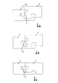
- Figuren 1a bis 1g -
- den Ablauf des Verriegelungsvorganges zweier Paneele in Seitenansicht an der Verbindungsstelle,
- Figuren 2a bis 2c -
- die Darstellung gemäß
Figuren 1b ,1d und1g mit deformiertem Verriegelungselement, - Figur 3a -
- ein erstes Verriegelungselement in Seitenansicht,
- Figur 3b -
- ein zweites Verriegelungselement in Seitenansicht,
- Figur 4 -
- eine Verbindungs- und Verriegelungsmöglichkeit zweier Bauplatten an den anderen Seitenkanten,
- Figur 5 -
- die schematische Darstellung, wie die Bauplatten an ihrer Querseite miteinander verbunden werden, wenn sie an ihrer Längsseite mit Paneelen in einer davor liegenden Reihe bereits verbunden sind.
- FIGS. 1a to 1g
- the sequence of the locking process of two panels in side view at the junction,
- FIGS. 2a to 2c
- the representation according to
Figures 1b .1d and1g with deformed locking element, - FIG. 3a -
- a first locking element in side view,
- FIG. 3b -
- a second locking element in side view,
- FIG. 4 -
- a connection and locking possibility of two building panels at the other side edges,
- FIG. 5 -
- the schematic representation of how the building panels are connected to each other at their transverse side, if they are already connected on their long side with panels in a row lying in front of it.
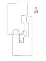
Die Erfindung soll für Fußbodenpaneele 1, 2 erläutert werden, die über eine erfindungsgemäße Verriegelungseinrichtung sowohl an ihren Längsseiten als auch an ihren Querseiten oder aber auch nur an einer ihrer Seiten miteinander verbunden werden können. Wird das Verriegelungselement nur an der Querseite der Fußbodenpaneele 1, 2 vorgesehen, was bevorzugt ist, kann die Verbindung und Verriegelung der Paneele an ihren Längsseiten so erfolgen, wie dies beispielsweise in der
In die Seitenkante II ist eine horizontal verlaufende Nut 21 eingefräst, die eine obere Wandung 21I, und eine parallel hierzu verlaufende untere Wandung 21II sowie einen Nutgrund 21III ausbildet. Die obere Wandung 21I und die untere Wandung 21II verlaufen parallel zur Oberseite 11 der Paneele 1, 2. An der gegenüberliegenden Seitenkante I ist in der Höhe der Nut 21 eine im Wesentlichen horizontal verlaufende Nut 12 eingefräst, die eine in einem Winkel zur Oberseite 11 verlaufende unter Wandung 12II und eine parallel zur Oberseite 11 verlaufende obere Wandung 12I ausbildet. In die Nut 21 an der Seitenkante II ist das Verriegelungselement 3 eingesetzt.In the side edge II a horizontally extending
Das Verriegelungselement 3 besteht im Wesentlichen aus einem halbkreisförmigen Kunststoffprofil mit Ausnehmungen. Es besteht aus dem Kopf 4 und dem sich hieran anschließenden Fuß 5. Die zur Oberseite 11 gerichtete Wandung des Kopfes 4 ist in einen gerade verlaufenden Bereich 4I und einen konvex gekrümmten Bereich 4II unterteilt. In der Ruhelage (
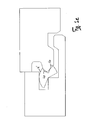
Zumindest der nach außen gerichtete Bereich 40 des Kopfes 4 und der Bereich 41, der durch die obere Wandung 4II des Kopfes 4 gebildet wird, ist ebenso wie der der äußere Bereich 50 des Fußes 5 elastisch deformierbar ausgebildet.At least the outwardly directed
Wie
In der Verbindung ist durch die Deformation der Bereiche 40, 41, 50 des Verriegelungselementes 3 eine Vorspannung eingestellt, die für eine Spielfreiheit in der Verbindungsstelle sorgt. Sowohl in vertikaler Richtung V als auch in horizontaler Richtung H ist die Spielfreiheit gewährleistet (
Die Paneele 1, 2 bestehen vorzugsweise aus einem Holzwerkstoff oder einem Holzwerkstoff-Kunststoff-Gemisch. Das Verriegelungselement 3 besteht aus Kunststoff. Die Oberseite 11 der Paneele 1, 2 ist mit einer hier nicht näher dargestellten Dekorschicht, vorzugsweise einem Holzdekor, versehen. An der Unterseite 13 kann in üblicher Weise ein Gegenzug aufgebracht sein, um Verwerfungen des Paneels 1, 2 zu verhindern.The
- 11
- Paneelpaneling
- 22
- Paneelpaneling
- 33
- Verriegelungselementlocking element
- 44
- Kopfhead
- 4I 4 I
- Wandungwall
- 4II 4 II
- Wandungwall
- 4III 4 III
- Wandungwall
- 4IV 4 IV
- Fasechamfer
- 55
- Fußfoot
- 5I 5 I
- Wandungwall
- 5II 5 II
- Wandungwall
- 5III 5 III
- Wandungwall
- 66
- Ausnehmungrecess
- 6a6a
- Wandungwall
- 6b6b
- Wandungwall
- 77
- Unterlippebottom lip
- 88th
- Nutgroove
- 99
- Nutgroove
- 1010
- Vorsprunghead Start
- 10I 10 l
- Kontaktflächecontact area
- 1111
- Oberseitetop
- 1212
- Nutgroove
- 12I 12 I
- Wandungwall
- 12II 12 II
- Wandungwall
- 1313
- Unterseitebottom
- 1414
- Kanteedge
- 1515
- Paneelpaneling
- 2020
- Absatzparagraph
- 20I 20 I
- Kontaktflächecontact area
- 2121
- Nutgroove
- 21I 21 I
- Wandungwall
- 21II 21 II
- Wandungwall
- 21III 21 III
- Nutgrundgroove base
- 3030
- Kerncore
- 3131
- Federfeather
- 3232
- Nutgroove
- 4040
- elastischer Bereichelastic range
- 4141
- elastischer Bereichelastic range
- 4242
- Verriegelungsnaselocking tab
- 5050
- elastischer Bereichelastic range
- II
- Seitenkanteside edge
- IIII
- Seitenkanteside edge
- IIIIII
- Seitenkanteside edge
- IVIV
- Seitenkanteside edge
- HH
- horizontale Richtunghorizontal direction
- LL
- Längsseitelong side
- Querseitetransverse side
- VV
- vertikale Richtungvertical direction
- αα
- Winkelangle
Claims (11)
dadurch gekennzeichnet, dass
characterized in that
Priority Applications (1)
| Application Number | Priority Date | Filing Date | Title |
|---|---|---|---|
| EP12004400.3A EP2674546A1 (en) | 2012-06-11 | 2012-06-11 | System for connecting and locking two building slabs |
Applications Claiming Priority (1)
| Application Number | Priority Date | Filing Date | Title |
|---|---|---|---|
| EP12004400.3A EP2674546A1 (en) | 2012-06-11 | 2012-06-11 | System for connecting and locking two building slabs |
Publications (1)
| Publication Number | Publication Date |
|---|---|
| EP2674546A1 true EP2674546A1 (en) | 2013-12-18 |
Family
ID=46384106
Family Applications (1)
| Application Number | Title | Priority Date | Filing Date |
|---|---|---|---|
| EP12004400.3A Withdrawn EP2674546A1 (en) | 2012-06-11 | 2012-06-11 | System for connecting and locking two building slabs |
Country Status (1)
| Country | Link |
|---|---|
| EP (1) | EP2674546A1 (en) |
Cited By (2)
| Publication number | Priority date | Publication date | Assignee | Title |
|---|---|---|---|---|
| DE102013113874A1 (en) * | 2013-12-11 | 2015-06-11 | Guido Schulte | Wall, floor or ceiling panel system with exchangeable plank |
| WO2017101910A1 (en) * | 2015-12-14 | 2017-06-22 | Guido Schulte | Mechanical connection for panels |
Citations (3)
| Publication number | Priority date | Publication date | Assignee | Title |
|---|---|---|---|---|
| WO2008004960A2 (en) * | 2006-12-08 | 2008-01-10 | Välinge Innovation AB | Mechanical locking of floor panels |
| EP2034106A1 (en) * | 2007-09-06 | 2009-03-11 | Flooring Technologies Ltd. | System for connecting and sealing two structural panels, in particular floor panels |
| DE102009022483A1 (en) * | 2009-05-25 | 2010-12-02 | Pergo (Europe) Ab | Set of panels, in particular floor panels |
-
2012
- 2012-06-11 EP EP12004400.3A patent/EP2674546A1/en not_active Withdrawn
Patent Citations (3)
| Publication number | Priority date | Publication date | Assignee | Title |
|---|---|---|---|---|
| WO2008004960A2 (en) * | 2006-12-08 | 2008-01-10 | Välinge Innovation AB | Mechanical locking of floor panels |
| EP2034106A1 (en) * | 2007-09-06 | 2009-03-11 | Flooring Technologies Ltd. | System for connecting and sealing two structural panels, in particular floor panels |
| DE102009022483A1 (en) * | 2009-05-25 | 2010-12-02 | Pergo (Europe) Ab | Set of panels, in particular floor panels |
Cited By (3)
| Publication number | Priority date | Publication date | Assignee | Title |
|---|---|---|---|---|
| DE102013113874A1 (en) * | 2013-12-11 | 2015-06-11 | Guido Schulte | Wall, floor or ceiling panel system with exchangeable plank |
| WO2017101910A1 (en) * | 2015-12-14 | 2017-06-22 | Guido Schulte | Mechanical connection for panels |
| US11339815B2 (en) | 2015-12-14 | 2022-05-24 | Guido Schulte | Mechanical connection for panels |
Similar Documents
| Publication | Publication Date | Title |
|---|---|---|
| DE102007042250B4 (en) | Device for connecting and locking two building panels, in particular floor panels | |
| EP1994241B1 (en) | Panel, particularly floor panel | |
| EP2057327B1 (en) | Panel, especially floor panel | |
| EP2213812B1 (en) | Panelling, in particular floor panelling | |
| DE102007017087B4 (en) | Panel, in particular floor panel | |
| EP2270291B1 (en) | Set of building panels with device for locking two of these panels | |
| DE102008003550B4 (en) | Device and method for locking two floor panels | |
| EP2037128B1 (en) | Device for connecting and locking two structural panels | |
| EP1606474B1 (en) | Device for connecting building boards, especially floor panels | |
| DE10159284A1 (en) | Building slab, especially floor panel | |
| EP2226447A1 (en) | Panelling, in particular floor panelling | |
| DE102006006124A1 (en) | Device for locking two building panels | |
| EP1917407A1 (en) | Detachable, flat components that can be fastened to each other, in particular floor covering components and corresponding component | |
| DE20220655U1 (en) | Locking system for panels with edge profiles, has groove profile and tongue profile which are engaged to form articulated joint that restores two panels to their installation plane when deflected either up or down | |
| WO2008122479A1 (en) | Floor, wall, or ceiling panels and method for the connection of said panels | |
| DE60100600T2 (en) | FASTENING DEVICE FOR THE SIDE EDGES OF PANELS, LATCHES OR WALL PANELS WITH POWER DISTRIBUTION | |
| EP1785535B1 (en) | Connecting device and method for connecting a wooden beam with a wooden supporting structure | |
| EP2397624B1 (en) | System and method for forming a floor covering from standard panels and at least one exchange panel | |
| EP2389488B1 (en) | Floor covering made of a composite board | |
| EP2674546A1 (en) | System for connecting and locking two building slabs | |
| DE102011122086A1 (en) | System for connecting and locking structural panels i.e. floor panels, has side edge comprising groove to accommodate short bracket, another groove formed at another edge and extension formed at long bracket and anchored into latter groove | |
| DE102011110071B4 (en) | Locking device for building panels | |
| EP3271527B1 (en) | Mechanical connection for panels and method for producing connecting means | |
| WO2009006926A1 (en) | 45° wall panel concept | |
| DE202020102526U1 (en) | Multi-profile panel |
Legal Events
| Date | Code | Title | Description |
|---|---|---|---|
| PUAI | Public reference made under article 153(3) epc to a published international application that has entered the european phase |
Free format text: ORIGINAL CODE: 0009012 |
|
| AK | Designated contracting states |
Kind code of ref document: A1 Designated state(s): AL AT BE BG CH CY CZ DE DK EE ES FI FR GB GR HR HU IE IS IT LI LT LU LV MC MK MT NL NO PL PT RO RS SE SI SK SM TR |
|
| AX | Request for extension of the european patent |
Extension state: BA ME |
|
| STAA | Information on the status of an ep patent application or granted ep patent |
Free format text: STATUS: THE APPLICATION IS DEEMED TO BE WITHDRAWN |
|
| 18D | Application deemed to be withdrawn |
Effective date: 20140619 |