EP2673599B1 - Vorrichtung und verfahren zur signalauswertung von wägezellen mit dehnmessstreifen - Google Patents
Vorrichtung und verfahren zur signalauswertung von wägezellen mit dehnmessstreifen Download PDFInfo
- Publication number
- EP2673599B1 EP2673599B1 EP12708648.6A EP12708648A EP2673599B1 EP 2673599 B1 EP2673599 B1 EP 2673599B1 EP 12708648 A EP12708648 A EP 12708648A EP 2673599 B1 EP2673599 B1 EP 2673599B1
- Authority
- EP
- European Patent Office
- Prior art keywords
- voltage
- ref
- strain gauge
- analogue
- digital converter
- Prior art date
- Legal status (The legal status is an assumption and is not a legal conclusion. Google has not performed a legal analysis and makes no representation as to the accuracy of the status listed.)
- Not-in-force
Links
- 238000000034 method Methods 0.000 title claims description 7
- 238000011156 evaluation Methods 0.000 claims description 7
- 238000005259 measurement Methods 0.000 claims description 5
- 238000005303 weighing Methods 0.000 description 3
- 238000011161 development Methods 0.000 description 2
- 238000012986 modification Methods 0.000 description 2
- 230000004048 modification Effects 0.000 description 2
- 238000012545 processing Methods 0.000 description 2
- 102000003712 Complement factor B Human genes 0.000 description 1
- 108090000056 Complement factor B Proteins 0.000 description 1
- 238000005452 bending Methods 0.000 description 1
- 230000037396 body weight Effects 0.000 description 1
- 230000001276 controlling effect Effects 0.000 description 1
- 230000001419 dependent effect Effects 0.000 description 1
- 238000005516 engineering process Methods 0.000 description 1
- 230000005284 excitation Effects 0.000 description 1
- 239000003292 glue Substances 0.000 description 1
- 230000001105 regulatory effect Effects 0.000 description 1
Images



Classifications
-
- G—PHYSICS
- G01—MEASURING; TESTING
- G01L—MEASURING FORCE, STRESS, TORQUE, WORK, MECHANICAL POWER, MECHANICAL EFFICIENCY, OR FLUID PRESSURE
- G01L1/00—Measuring force or stress, in general
- G01L1/20—Measuring force or stress, in general by measuring variations in ohmic resistance of solid materials or of electrically-conductive fluids; by making use of electrokinetic cells, i.e. liquid-containing cells wherein an electrical potential is produced or varied upon the application of stress
- G01L1/22—Measuring force or stress, in general by measuring variations in ohmic resistance of solid materials or of electrically-conductive fluids; by making use of electrokinetic cells, i.e. liquid-containing cells wherein an electrical potential is produced or varied upon the application of stress using resistance strain gauges
- G01L1/225—Measuring circuits therefor
-
- G—PHYSICS
- G01—MEASURING; TESTING
- G01G—WEIGHING
- G01G3/00—Weighing apparatus characterised by the use of elastically-deformable members, e.g. spring balances
- G01G3/12—Weighing apparatus characterised by the use of elastically-deformable members, e.g. spring balances wherein the weighing element is in the form of a solid body stressed by pressure or tension during weighing
- G01G3/14—Weighing apparatus characterised by the use of elastically-deformable members, e.g. spring balances wherein the weighing element is in the form of a solid body stressed by pressure or tension during weighing measuring variations of electrical resistance
- G01G3/142—Circuits specially adapted therefor
Definitions
- the invention relates to a device and a method for signal evaluation of load cells with strain gauges.
- Modern electromechanical scales usually work either on the principle of electromagnetic force compensation or with load cells that work with strain gauges (DMS). These change their electrical resistance even at low deformations. They are glued with special glue on components that deform slightly under load. With DMS scales of all sizes, from household scales to crane scales, can be realized. So describes z. B. DE 3538178 A1 a personal scale for the body weight. DE 10135238 A1 describes a scale for food and DE 102008014838 B3 a Dosiermengenbaumwachungsvortechnisch for coffee machines. This works like the one in DE 19838371 C2 described scales with one or more load cells. When using multiple load cells their signals are added in a signal processing device. The load cells are designed as leaf springs to which the strain gauges are glued.
- DE 20023524 U1 describes a force measuring element for a balance consisting of a beam having two exceptions. Due to the reduced cross sections arise two bending points, between which results in loading the ends of the beam parallel guidance.
- the measuring signal of the force measuring element is derived from a DMS, which is glued to the top of the beam. Four of these force measuring elements, which are connected as a Wheatstone bridge, form the weighing cells of the balance.
- the strain gauges When loaded, the strain gauges are stretched or compressed, changing their electrical resistance. As a result, the voltage state changes in the zero branch of the bridge circuit, which is amplified and displayed with, for example, a pointer instrument.
- the amplified voltage state is also digitized in an analog-to-digital converter (ADC), processed with digital signal processing and displayed with a signal output.
- ADC analog-to-digital converter
- a disadvantage of the scales described is that due to the small output signal of the load cells, which is typically at 2 mV per volt supply voltage, high-quality and therefore expensive amplifier circuits must be used. Alternatively, ADCs with a very high resolution can also be used when digitizing the signal. But even these are not available in the low-cost segment.
- the US 4,763,739A discloses essentially an energy efficient balance with strain gauges operated at three different operating currents.
- the highest current is used for precise weighing, the average current is used to indicate whether a weight is on the scale, while the lowest current is provided for electrical balancing of the strain gauges.
- the balance changes regularly between the low and medium operating currents. If a weight is detected on the balance during the middle operating phase, the balance changes to the highest operating current.
- the signal generated by the strain gauge is then amplified and digitized, the reference voltage for the analog-to-digital converter being derived from the current through the strain gauge.
- the GB 1 478 156A essentially relates to a device with which a digital signal is generated when a resistance measuring bridge is unbalanced. For this purpose, a voltage having a first polarity is applied to the input of the bridge during a first phase and a voltage having a second polarity opposite thereto during a second phase, the amounts of which are equal. The resulting signals at the output of the bridge are digitized and combined with one another in such a way that external influences are disregarded, so that the combined signal corresponds to the unbalanced state of the bridge.
- the references for the two analog / digital converters are derived from the operating voltages of the bridge.
- the invention has for its object to realize a cost-effective components high-resolution weighing cell evaluation.
- this object is achieved by a device having the features of patent claim 1 and a method having the features of patent claim 9, by two different operating points of the strain gage are set in two successive measurements.
- the voltage in the zero branch of the bridge circuit of the strain gauge is amplified in a differential amplifier and digitized with an ADC.
- the same voltage references are used for the ADC and for setting the operating point of the strain gauge.
- the digitized offset and the output value of the load cell are determined from the two measured values.
- the advantages achieved by the invention are in particular that the temperature-dependent offset voltages are compensated by simple operational amplifiers.
- one or more load cells can be used.
- FIG. 1 is shown schematically the structure of the evaluation circuit including load cell.
- the operating voltage is taken from a DC bus 1, to which a load cell with a strain gauge (DMS) 2 is connected.
- the DMS 2 is connected as a Wheatstone bridge.
- the current I through the DMS 2 is controlled by a current source 3.
- the voltage ⁇ U in the zero branch of the bridge circuit is amplified by a factor A in a differential amplifier 4 and digitized with an analog-to-digital converter (ADC) 5.
- ADC analog-to-digital converter
- the same voltage reference 6 and 7 are used for the ADC 5 and the current source 3.
- U offset offset voltages U offset are also amplified in the differential amplifier 4 due to imbalances in the differential amplifier 4 or, for example, by thermal voltages at connection points. This results in the input voltage at the ADC 5:
- U ADC A ⁇ ⁇ ⁇ U + U offset
- N N Max ⁇ A ⁇ ⁇ ⁇ U + U offset U ref
- the first voltage reference 6 can be replaced by a second voltage reference 7.
- the current source 3 in two different operating points I 1 and I 2 according to equation (2) are operated.
- the measured weight results from the elongation via a calibration so that the quotient in equation (10) can be replaced by a calibration factor.
- the operation and the switch position on the voltage references 6, 7 can be easily run with a simple calculator 8 and possibly display.
- the offset voltage can significantly exceed the voltage in the zero branch of the bridge circuit when using non-precision differential amplifiers. Therefore, it may be necessary to have to select the ADC 5 in its resolution much higher than the desired one would require resolution of the balance.
- FIG. 2 in addition, the offset voltage of the differential amplifier 4 is reduced with a carrier frequency method.
- the current is modulated with an H-bridge consisting of the electronic switches 9a to 9d in its flow direction through the DMS 2.
- the amplitude difference-modulated by the strain gage bridge excursion AC voltage difference signal is amplified in the differential amplifier 4 and demodulated in a demodulator 10.
- the demodulation acts like a narrowband bandpass that only lets through the excitation frequency. Subsequently, this is filtered out by a low-pass filter 11, so that a DC voltage is present at the output, which is proportional to the DMS deflection.
- offset voltages in the demodulator 10, ADC 5 or within the current source 3 can not be reduced in this way. These are reduced by the variation of the operating point of the current source 3 and the following evaluation in the arithmetic unit 8.
- a simple microcontroller is well suited to implement the calculator 8. Even simple microcontrollers often have an ADC 5. However, this does not usually have the resolution required for the application. With oversampling techniques, the resolution can usually be increased sufficiently at the expense of the measurement frequency. The reduced measuring frequency can be overcome in most balance applications.
- the reference voltages 6 and 7 are also applied directly to the DMS 2.
- the respective DMS 2 are now connected in parallel.
- the offset voltage of the differential amplifier 4 can also be reduced here, as described above, with a carrier frequency method.
- a dead time between the two states with different current direction through the DMS 2 are maintained, so that, for example, the switches 9a and 9c are not connected simultaneously, which would lead to an excessive current flow in the bridge.
- This increased current flow is in the configuration according to FIG. 2 prevented by the power source 3.
- This dead time between the two states leads to asymmetries in the demodulator 10.
Landscapes
- Physics & Mathematics (AREA)
- General Physics & Mathematics (AREA)
- Measurement Of Force In General (AREA)
- Measurement Of Length, Angles, Or The Like Using Electric Or Magnetic Means (AREA)
Description
- Die Erfindung betrifft eine Vorrichtung und ein Verfahren zur Signalauswertung von Wägezellen mit Dehnmessstreifen.
- Moderne elektromechanische Waagen arbeiten zumeist entweder nach dem Prinzip der elektromagnetischen Kraftkompensation oder mit Wägezellen, die mit Dehnmessstreifen (DMS) arbeiten. Diese ändern schon bei geringen Verformungen ihren elektrischen Widerstand. Man klebt sie mit Spezialkleber auf Bauteile, die sich unter Belastung minimal verformen. Mit DMS können Waagen aller Größenordnungen, von Haushaltswaagen bis hin zu Kranwaagen, realisiert werden. So beschreibt z. B.
DE 3538178 A1 eine Personenwaage für das Körpergewicht.DE 10135238 A1 beschreibt eine Waage für Lebensmittel undDE 102008014838 B3 eine Dosiermengenüberwachungsvorrichtung für Kaffeemaschinen. Diese arbeitet wie die inDE 19838371 C2 beschriebenen Waagen mit einer oder mehreren Wägezellen. Bei dem Einsatz mehrerer Wägezellen werden ihre Signale in einer Signalverarbeitungsvorrichtung addiert. Die Wägezellen sind als Blattfedern ausgeführt, auf die die DMS aufgeklebt sind. -
DE 20023524 U1 beschreibt ein Kraftmesselement für eine Waage, das aus einem Balken besteht, der zwei Ausnahmen aufweist. Durch die verringerten Querschnitte entstehen zwei Biegestellen, zwischen denen sich bei Belastung der Enden des Balkens eine Parallelführung ergibt. Das Messsignal des Kraftmesselements wird aus einem DMS abgeleitet, der auf der Oberseite des Balkens aufgeklebt ist. Vier von diesen Kraftmesselementen, die als Wheatston'sche Brücke geschaltet sind, bilden die Wägezellen der Waage. - Bei Belastung werden die DMS gestreckt oder gestaucht, wobei sich deren elektrischer Widerstand ändert. Dadurch verändert sich der Spannungszustand im Nullzweig der Brückenschaltung, der verstärkt und mit z.B. einem Zeigerinstrument angezeigt wird. Neben dieser rein analogen Anzeige wird, wie z.B. in
DE 102008014838 B3 beschrieben, der verstärkte Spannungszustand auch in einem Analog/Digital-Umsetzer (ADC) digitalisiert, mit einer digitalen Signalverarbeitung aufbereitet und mit einer Signalausgabe angezeigt. - Nachteilig an den beschriebenen Waagen ist, dass aufgrund des kleinen Ausgangssignals der Wägezellen, das typischerweise bei 2 mV pro Volt Speisespannung liegt, hochwertige und damit teure Verstärkerschaltungen eingesetzt werden müssen. Alternativ können auch bei Digitalisierung des Signals ADCs mit einer sehr hohen Auflösung verwendet werden. Aber auch diese stehen im Low-cost-Segment nicht zur Verfügung.
- Die
US 4,763,739A offenbart im Wesentlichen eine energieeffiziente Waage mit Dehnmessstreifen, die mit drei verschiedenen Betriebsströmen betrieben wird. Der höchste Strom dient dabei zum präzisen Wiegen, der mittlere Strom dient zur Indikation, ob ein Gewicht auf der Waage liegt, während der niedrigste Strom zur elektrischen Balancierung der Dehnmessstreifen vorgesehen ist. Im Standby-Betrieb wechselt die Waage regelmäßig zwischen dem niedrigen und dem mittleren Betriebsstrom. Wenn während der Phase mittleren Betriebsstroms ein Gewicht auf der Waage erkannt wird, wechselt die Waage in den höchsten Betriebsstrom. Das mit dem Dehnmessstreifen erzeugte Signal wird dann verstärkt und digitalisiert, wobei die Referenzspannung für den Analog/Digital-Wandler aus dem Strom durch den Dehnmessstreifen abgeleitet wird. - Die
GB 1 478 156A - Der Erfindung liegt die Aufgabe zugrunde, mit kostengünstigen Komponenten eine hochauflösende Wägezellenauswertung zu realisieren.
- Erfindungsgemäß wird diese Aufgabe durch eine Vorrichtung mit den Merkmalen des Patentanspruchs 1 und ein Verfahren mit den Merkmalen des Patentanspruchs 9 gelöst, indem bei zwei aufeinander folgenden Messungen zwei unterschiedliche Arbeitspunkte des DMS eingestellt werden. Die Spannung im Nullzweig der Brückenschaltung des DMS wird in einem Differenzverstärker verstärkt und mit einem ADC digitalisiert. Dabei werden für den ADC und zur Einstellung des Arbeitspunktes des DMS dieselben Spannungsreferenzen genutzt. In einem Rechenwerk wird aus den beiden Messwerten der digitalisierte Offset und der Ausgangswert der Wägezelle ermittelt.
- Die mit der Erfindung erzielten Vorteile bestehen insbesondere darin, dass die temperaturabhängigen Offsetspannungen von einfachen Operationsverstärkern kompensiert werden. Zur Steigerung der Flexibilität können eine oder mehrere Wägezellen verwendet werden.
- Weitere Einzelheiten der Erfindung werden anhand der Figuren beschrieben:
-
Figur 1 zeigt schematisch den Aufbau der Auswerteschaltung inklusive Wägezelle. -
Figur 2 zeigt schematisch eine vorteilhafte Weiterbildung der Erfindung. -
Figur 3 zeigt eine Abwandlung der Erfindung. -
Figur 4 zeigt schematisch eine weitere vorteilhafte Weiterbildung der Erfindung. - In
Figur 1 ist schematisch der Aufbau der Auswerteschaltung inklusive Wägezelle gezeigt. Die Betriebsspannung wird aus einem DC-Bus 1 entnommen, an dem eine Wägezelle mit einem Dehnmessstreifen (DMS) 2 angeschlossen ist. Der DMS 2 ist als Wheatston'sche Brücke geschaltet. Der Strom I durch den DMS 2 wird durch eine Stromquelle 3 geregelt. Die dehnungsbedingte Widerstandsänderung ΔR des DMS 2 ist proportional zur Elongation ε mit der Proportionalitätskonstanten k und dem Gesamtwiderstand der Brücke R:
- Die Spannung ΔU im Nullzweig der Brückenschaltung wird in einem Differenzverstärker 4 um den Faktor A verstärkt und mit einem Analog/Digital-Umsetzer (ADC) 5 digitalisiert. Dabei werden für den ADC 5 und die Stromquelle 3 dieselbe Spannungsreferenz 6 und 7 genutzt. Der Strom I wird daher durch den Referenzwiderstand RI und die Spannungsreferenz Uref bestimmt.

- Neben dem dehnungsbedingten Signal ΔU werden in dem Differenzverstärker 4 aber auch Off-set-Spannungen Uoffset aufgrund von Ungleichgewichten im Differenzverstärker 4 oder z.B. von Thermospannungen an Verbindungsstellen verstärkt. Somit ergibt sich für die Eingangsspannung am ADC 5:

- Für den digitalisierten Wert N am Ausgang des ADC 5 ergibt sich somit:

- Dabei ist Nmax der maximale Ausgangswert des ADC 5 und Uref die Referenzspannung. Mit Gleichung (1) und (2) erhält man:

- Über Schalter kann die erste Spannungsreferenz 6 durch eine zweite Spannungsreferenz 7 ersetzt werden. So kann die Stromquelle 3 in zwei verschiedenen Arbeitspunkten I1 und I2 gemäß Gleichung (2) betrieben werden. Aus zwei Messungen N1 und N2 mit jeweils der ersten und der zweiten Spannungsreferenz kann die Offset-Spannung ermittelt werden zu:

- Damit ergibt sich die Elongation ε aus diesen beiden Messungen zu:

- Die Werte der Referenzspannungen lassen sich über einen Faktor B wie folgt in Beziehung setzen:

- Damit vereinfacht sich Gleichung (7) zu:

- Durch geeignete Wahl von B, z.B. B=3/4, vereinfacht sich der Ausdruck weiter zu:

- Das gemessene Gewicht ergibt sich aus der Elongation über eine Kalibrierung, so dass der Quotient in Gleichung (10) durch einen Kalibrierfaktor ersetzt werden kann. Somit lassen sich die Operation und die Schalterstellung an den Spannungsreferenzen 6, 7 leicht mit einem einfachen Rechenwerk 8 ausführen und gegebenenfalls zur Anzeige bringen.
- Die Offset-Spannung kann beim Einsatz von Nicht-Präzisions-Differenzverstärkern die Spannung im Nullzweig der Brückenschaltung deutlich übertreffen. Daher kann es notwendig sein, den ADC 5 in seiner Auflösung deutlich höher auswählen zu müssen als es die gewünschte Auflösung der Waage benötigen würde. In einer vorteilhaften Weiterbildung der Erfindung, die in
Figur 2 schematisch gezeigt ist, wird zusätzlich die Offset-Spannung des Differenzverstärkers 4 mit einem Trägerfrequenzverfahren reduziert. - Dazu wird der Strom mit einer H-Brücke bestehend aus den elektronischen Schaltern 9a bis 9d in seiner Flussrichtung durch das DMS 2 moduliert. Das durch die DMS-Brückenauslenkung amplitudenmodulierte Wechselspannungsdifferenzsignal wird im Differenzverstärker 4 verstärkt und in einem Demodulator 10 demoduliert. Die Demodulation wirkt wie ein schmalbandiger Bandpass, der nur die Anregungsfrequenz durchlässt. Anschließend wird diese durch einen Tiefpass 11 ausgefiltert, so dass am Ausgang eine Gleichspannung anliegt, die zu der DMS-Auslenkung proportional ist. Offset-Spannungen im Demodulator 10, ADC 5 oder innerhalb der Stromquelle 3 lassen sich so allerdings nicht reduzieren. Diese werden durch die Variation des Arbeitspunkts der Stromquelle 3 und die folgende Auswertung im Rechenwerk 8 reduziert.
- Ein einfacher Mikrocontroller ist gut geeignet, um das Rechenwerk 8 zu realisieren. Oft verfügen selbst einfache Mikrocontroller über einen ADC 5. Dieser hat allerdings meistens nicht die für die Applikation benötigte Auflösung. Mit Oversampling-Techniken kann die Auflösung zumeist zu Lasten der Messfrequenz ausreichend erhöht werden. Die reduzierte Messfrequenz ist bei den meisten Waagenapplikationen zu verschmerzen.
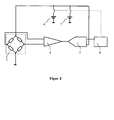
- In einer Abwandlung der Erfindung können, wie in
Figur 3 dargestellt, die Referenzspannungen 6 und 7 auch direkt an den DMS 2 angelegt werden. Bei der Verwendung von mehreren Wägezellen werden die jeweiligen DMS 2 nun aber parallel geschaltet. Die Offset-Spannung des Differenzverstärkers 4 kann auch hier, wie oben beschrieben, mit einem Trägerfrequenzverfahren reduziert werden. Allerdings muss bei der Ansteuerung der H-Brücke (vergleicheFigur 2 ) eine Totzeit zwischen den beiden Zuständen mit unterschiedlicher Stromrichtung durch das DMS 2 eingehalten werden, damit z.B. die Schalter 9a und 9c nicht gleichzeitig geschaltet sind, was zu einem überhöhten Stromfluss in der Brücke führen würde. Dieser erhöhte Stromfluss wird in der Konfiguration gemäßFigur 2 durch die Stromquelle 3 verhindert. Diese Totzeit zwischen den beiden Zuständen führt zu Asymmetrien im Demodulator 10. - Die bisherigen Ausführungsbeispiele der Erfindung nutzen nicht direkt den in Gleichung (1) beschriebenen Zusammenhang zwischen der Elongation ε und der relativen Widerstandsänderung ΔR/R. Sie setzen vielmehr ein ohmsches Verhalten des DMS 2 voraus und nutzen die über das Ohmsche Gesetz abgeleitete Form ΔU/U. Bei DMS 2 mit Widerstandsdraht ist diese Annahme im linearen Bereich des DMS 2 sicherlich korrekt. DMS 2 in Dickschichttechnik zeigen zumeist kein ohmsches Verhalten. Die in
Figur 4 schematisch gezeigte Weiterbildung der Erfindung beruht auf der direkten Nutzung von Gleichung (1), indem der Strom durch den DMS 2 von einer Stromquelle 3 entsprechend der jeweils geschalteten Spannungsreferenz 6 oder 7 geregelt und die Referenzspannung für den ADC 5 mittels Differenzverstärker 12 aus dem Spannungsabfall über dem DMS 2 abgeleitet wird. Somit wird die Referenzspannung des ADC 5 direkt aus den beiden durch die jeweilige Spannungsreferenz bestimmten Arbeitspunkten des DMS 2 abgeleitet.
Claims (9)
- Vorrichtung zur Signalauswertung von Wägezellen mit mindestens einem in eine Brückenschaltung geschalteten Dehnmessstreifen (2), mindestens einem Differenzverstärker (4) zur Verstärkung einer im Nullzweig der Brückenschaltung anliegenden Spannung (ΔU), sowie einem Analog/Digital-Umsetzer (5) zur Erzeugung eines digitalisierten Wertes (N) der verstärkten Spannung (ΔU), gekennzeichnet durch eine erste und eine zweite Referenzspannungsquelle (6, 7) zur Erzeugung einer ersten bzw. einer zweiten Referenzspannung (Uref1, Uref2) zum Betreiben des Dehnmessstreifens (2) an zwei verschiedenen Arbeitspunkten sowie zum Ableiten einer Referenz für den Analog/Digital-Umsetzer (5) aus der jeweils gleichen Referenzspannung (Uref1, Uref2), sowie einem Rechenwerk (8), dem die mit den beiden Referenzspannungen (Uref1, Uref2) ermittelten und digitalisierten Werte (N1, N2) zugeführt werden, wobei sich ein zu messendes Gewicht durch Berechnung der Elongation (ε) des Dehnmessstreifens gemäß folgender Formel:

und Ermittlung des Quotienten
- Vorrichtung nach Anspruch 1, mit einem Verstärker, mit dem eine Betriebsspannung des Dehnmessstreifens (2) an den beiden Arbeitspunkten linear aus der jeweiligen ersten bzw. zweiten Referenzspannung (Uref1, Uref2) abgeleitet wird.
- Vorrichtung nach Anspruch 1, mit einer Stromquelle (3), mit der ein Strom (I) durch den Dehnmessstreifen (2) linear aus der jeweiligen ersten bzw. zweiten Referenzspannung (U-ref1, Uref2) ableitet wird.
- Vorrichtung nach Anspruch 3, bei der der Strom (I) durch den Dehnmessstreifen (2) mit einer H-Brücke bestehend aus vier elektronischen Schaltern (9a, 9b, 9c, 9d) in seiner Flussrichtung moduliert wird und das durch die Auslenkung amplitudenmodulierte Wechselspannungsdifferenzsignal des Dehnmessstreifens (2) in dem Differenzverstärker (4) verstärkt, in einem Demodulator (10) demoduliert und mit einem Tiefpass (11) gefiltert wird, bevor es dem Analog/Digital-Umsetzer (5) zur Erzeugung des digitalisierten Wertes (N1, N2) zugeführt wird.
- Vorrichtung nach Anspruch 3, bei der die Referenz für den Analog/Digital-Umsetzer (5) mittels eines weiteren Differenzverstärkers (12) aus dem Spannungsabfall (ΔU) über dem Dehnmessstreifen (2) abgeleitet wird.
- Vorrichtung nach Anspruch 3, 4 oder 5, bei der die verstärkten Signale mehrerer Dehnmessstreifen (2), die sich in einer Reihenschaltung im Strompfad der Stromquelle (3) befinden, mit einem Summierverstärker addiert werden, so dass das Summensignal im Analog/Digital-Umsetzer (5) digitalisiert wird.
- Vorrichtung nach Anspruch 1 bis 6, bei der das Rechenwerk (8) mit einem Mikrokontroller realisiert ist.
- Vorrichtung nach Anspruch 7, bei der der Analog/Digital-Umsetzer (5) im Mikrokontroller integriert ist.
- Verfahren zur Signalauswertung von Wägezellen mit mindestens einem in eine Brückenschaltung geschalteten Dehnmessstreifen (2), mindestens einem Differenzverstärker (4) zur Verstärkung einer im Nullzweig der Brückenschaltung anliegenden Spannung (ΔU), sowie einem Analog/Digital-Umsetzer (5) zur Erzeugung eines digitalisierten Wertes (N) der verstärkten Spannung (ΔU), dadurch gekennzeichnet, dass ein Gewicht mit zwei aufeinander folgenden Messungen ermittelt wird, bei denen der Dehnmessstreifen (2) an zwei unterschiedlichen, durch jeweils eine erste bzw. eine zweite Referenzspannung (Uref1, Uref2) bestimmten Arbeitspunkten betrieben wird, wobei die Referenz für den Analog/DigitalUmsetzer (5) aus der jeweils gleichen Referenzspannung (Uref1, Uref2) abgeleitet wird, die auch den jeweiligen Arbeitspunkt des Dehnmessstreifens (2) bestimmt, und aus den beiden digitalisierten Werten (N1, N2) in einem Rechenwerk (8) das Gewicht durch Berechnung der Elongation (ε) des Dehnmessstreifens gemäß folgender Formel :

und Ermittlung des Quotienten
Priority Applications (1)
| Application Number | Priority Date | Filing Date | Title |
|---|---|---|---|
| PL12708648T PL2673599T3 (pl) | 2011-02-10 | 2012-02-09 | Urządzenie i sposób analizy sygnałów czujników obciążenia z paskami tensometrycznymi |
Applications Claiming Priority (3)
| Application Number | Priority Date | Filing Date | Title |
|---|---|---|---|
| DE102011010945 | 2011-02-10 | ||
| DE102011013658A DE102011013658B4 (de) | 2011-02-10 | 2011-03-11 | Vorrichtung zur Signalauswertung von Wägezellen mit Dehnmessstreifen |
| PCT/DE2012/200006 WO2012107040A1 (de) | 2011-02-10 | 2012-02-09 | Vorrichtung und verfahren zur signalauswertung von wägezellen mit dehnmessstreifen |
Publications (2)
| Publication Number | Publication Date |
|---|---|
| EP2673599A1 EP2673599A1 (de) | 2013-12-18 |
| EP2673599B1 true EP2673599B1 (de) | 2014-12-24 |
Family
ID=46579705
Family Applications (1)
| Application Number | Title | Priority Date | Filing Date |
|---|---|---|---|
| EP12708648.6A Not-in-force EP2673599B1 (de) | 2011-02-10 | 2012-02-09 | Vorrichtung und verfahren zur signalauswertung von wägezellen mit dehnmessstreifen |
Country Status (8)
| Country | Link |
|---|---|
| US (1) | US9052247B2 (de) |
| EP (1) | EP2673599B1 (de) |
| AU (1) | AU2012214000B2 (de) |
| DE (2) | DE102011013658B4 (de) |
| ES (1) | ES2528896T3 (de) |
| PL (1) | PL2673599T3 (de) |
| PT (1) | PT2673599E (de) |
| WO (1) | WO2012107040A1 (de) |
Families Citing this family (7)
| Publication number | Priority date | Publication date | Assignee | Title |
|---|---|---|---|---|
| US9759626B2 (en) * | 2014-08-11 | 2017-09-12 | Goodrich Corporation | System and method to adjust a force zero reference |
| CN105571691A (zh) * | 2014-10-09 | 2016-05-11 | 梅特勒-托利多(常州)精密仪器有限公司 | 称重传感器、称重网络及监测方法 |
| CN105698912B (zh) * | 2016-03-15 | 2024-07-09 | 梅特勒-托利多(常州)精密仪器有限公司 | 在力标准机上一次测量两只柱式称重传感器的气动测试装置及测试方法 |
| DE102018110100B4 (de) * | 2018-04-26 | 2020-06-18 | Minebea Intec GmbH | Galvanisch getrennte, symmetrische Sensorversorgung eines Analog-Digital-Wandlers für asymmetrische Versorgung |
| CN111623909B (zh) * | 2019-02-28 | 2021-07-30 | 北京新能源汽车股份有限公司 | 一种双叉臂二力杆的受力测试方法 |
| CN115210682A (zh) * | 2020-03-19 | 2022-10-18 | 深圳纽迪瑞科技开发有限公司 | 压力感应式结构及电子产品 |
| KR20240168178A (ko) * | 2023-05-22 | 2024-11-29 | 주식회사 에이엘로봇 | 토크 센서 모듈 |
Family Cites Families (11)
| Publication number | Priority date | Publication date | Assignee | Title |
|---|---|---|---|---|
| SE377382B (de) * | 1973-10-23 | 1975-06-30 | Bofors Ab | |
| DE3538178A1 (de) * | 1985-10-26 | 1987-04-30 | Krups Stiftung | Waage, insbesondere personenwaage |
| US4763739A (en) * | 1987-11-09 | 1988-08-16 | Hobart Corporation | Energy efficient scale |
| US4909340A (en) * | 1989-02-03 | 1990-03-20 | John Chatillon & Sons Inc. | Electronic weighing scale |
| DE19838371C2 (de) * | 1998-08-24 | 2003-04-10 | Beurer Gmbh & Co | Waage |
| DE19932289C1 (de) | 1999-07-10 | 2001-01-04 | Soehnle Ag Montlingen | Kraftmesselement für eine Waage |
| DE10135238A1 (de) * | 2001-07-24 | 2003-02-20 | Mettler Toledo Gmbh | Waage für die Lebensmittelverarbeitung |
| DE10353414B3 (de) * | 2003-11-15 | 2005-01-27 | Sartorius Ag | Elektronische Waage |
| DE102006050832B4 (de) * | 2006-10-27 | 2012-07-26 | Infineon Technologies Ag | In-Betrieb-Test eines Signalpfades mittels wenigstens zweier Testsignale |
| JP5515161B2 (ja) * | 2007-12-27 | 2014-06-11 | 株式会社タニタ | 重量計 |
| DE102008014838B3 (de) * | 2008-03-07 | 2009-09-10 | Brod, Werner, Dipl.-Ing. (FH) | Dosiermengenüberwachungsvorrichtung, Kaffeemaschine und Verfahren zum Zubereiten eines Brühgetränks |
-
2011
- 2011-03-11 DE DE102011013658A patent/DE102011013658B4/de not_active Expired - Fee Related
-
2012
- 2012-02-09 AU AU2012214000A patent/AU2012214000B2/en not_active Ceased
- 2012-02-09 PL PL12708648T patent/PL2673599T3/pl unknown
- 2012-02-09 PT PT12708648T patent/PT2673599E/pt unknown
- 2012-02-09 ES ES12708648.6T patent/ES2528896T3/es active Active
- 2012-02-09 EP EP12708648.6A patent/EP2673599B1/de not_active Not-in-force
- 2012-02-09 US US13/984,325 patent/US9052247B2/en active Active
- 2012-02-09 WO PCT/DE2012/200006 patent/WO2012107040A1/de not_active Ceased
- 2012-02-09 DE DE112012000768.9T patent/DE112012000768A5/de not_active Withdrawn
Also Published As
| Publication number | Publication date |
|---|---|
| ES2528896T3 (es) | 2015-02-13 |
| US9052247B2 (en) | 2015-06-09 |
| DE102011013658B4 (de) | 2012-12-13 |
| DE112012000768A5 (de) | 2014-02-13 |
| WO2012107040A1 (de) | 2012-08-16 |
| US20140182387A1 (en) | 2014-07-03 |
| AU2012214000A1 (en) | 2013-09-12 |
| PT2673599E (pt) | 2015-03-12 |
| AU2012214000B2 (en) | 2015-08-13 |
| PL2673599T3 (pl) | 2015-05-29 |
| EP2673599A1 (de) | 2013-12-18 |
| DE102011013658A1 (de) | 2012-08-16 |
Similar Documents
| Publication | Publication Date | Title |
|---|---|---|
| DE102011013658B4 (de) | Vorrichtung zur Signalauswertung von Wägezellen mit Dehnmessstreifen | |
| DE112012005548B4 (de) | Ausgangswertkorrekturverfahren für eine Sensorvorrichtung für eine physikalische Grösse, Ausgangskorrekturverfahren für einen Sensor für eine physikalische Grösse, Sensorvorrichtung für eine physikalische Grösse und Ausgangswertkorrekturvorrichtung für einen Sensor für eine physikalische Grösse | |
| EP3195000B1 (de) | Kalibrierung von stromsensoren mittels referenzstrom während der strommessung | |
| DE10160794B4 (de) | Signalverarbeitungseinrichtung für einen Druckschalter od. dgl. | |
| DE102011102483A1 (de) | Verfahren zum Betreiben einer Hallsensoranordnung und Hallsensoranordnung | |
| DE102018110668A1 (de) | Impedanzkenngrößenschaltung für einen elektrochemischen Sensor | |
| EP0280303A2 (de) | Verfahren und Anordnung zur automatischen Messung von Gleichströmen | |
| EP3475671B1 (de) | Wägezelle mit kompensation von temperaturdifferenzen | |
| EP2959306B1 (de) | Leistungsmessgerät mit interner kalibrierung von diodendetektoren | |
| EP3074726B1 (de) | Induktiver messtaster und verfahren zum betreiben eines induktiven messtasters | |
| DE69403373T2 (de) | Kraftmessinstrument | |
| DE10334517B4 (de) | Messgerät für elektrische Energie für ein Wechselstromnetz | |
| DE102023127520A1 (de) | Verfahren zur Impedanzmessung elektrischer Bauelemente | |
| DE102012211022A1 (de) | Verfahren und Vorrichtung zur Stromregelung für einen Umrichter | |
| EP2826147A1 (de) | Integrierender a/d-wandler | |
| DE602004007691T2 (de) | Verfahren zur winkelbestimmung | |
| DE102015110221A1 (de) | Kalibierbarer Mehrphasen-Gleichstromwandler | |
| DE102012217472A1 (de) | Bestimmung von gleichanteilsbehafteten Strömen in einem Stromrichter mit Wechselstromwandlern | |
| DE102007007406B4 (de) | Elektronischer Druckschalter | |
| EP2056460B1 (de) | Verfahren und Anordnung eines Messverstärkers zur Korrektur von Eingangssignalen | |
| DE3532333A1 (de) | Elektrischer fuehler fuer druck- und kraftmessungen | |
| DE3326204A1 (de) | Verfahren und messschaltungsanordnung zur driftkorrektur bei der digitalisierung von messspannungen | |
| DE102018110100B4 (de) | Galvanisch getrennte, symmetrische Sensorversorgung eines Analog-Digital-Wandlers für asymmetrische Versorgung | |
| EP2207042B1 (de) | Drehstromzähler | |
| WO2020216611A1 (de) | Verfahren zur präzisen erfassung eines signals zum beispiel eines sensors |
Legal Events
| Date | Code | Title | Description |
|---|---|---|---|
| PUAI | Public reference made under article 153(3) epc to a published international application that has entered the european phase |
Free format text: ORIGINAL CODE: 0009012 |
|
| 17P | Request for examination filed |
Effective date: 20130910 |
|
| AK | Designated contracting states |
Kind code of ref document: A1 Designated state(s): AL AT BE BG CH CY CZ DE DK EE ES FI FR GB GR HR HU IE IS IT LI LT LU LV MC MK MT NL NO PL PT RO RS SE SI SK SM TR |
|
| DAX | Request for extension of the european patent (deleted) | ||
| GRAP | Despatch of communication of intention to grant a patent |
Free format text: ORIGINAL CODE: EPIDOSNIGR1 |
|
| INTG | Intention to grant announced |
Effective date: 20140902 |
|
| GRAS | Grant fee paid |
Free format text: ORIGINAL CODE: EPIDOSNIGR3 |
|
| GRAA | (expected) grant |
Free format text: ORIGINAL CODE: 0009210 |
|
| AK | Designated contracting states |
Kind code of ref document: B1 Designated state(s): AL AT BE BG CH CY CZ DE DK EE ES FI FR GB GR HR HU IE IS IT LI LT LU LV MC MK MT NL NO PL PT RO RS SE SI SK SM TR |
|
| REG | Reference to a national code |
Ref country code: GB Ref legal event code: FG4D Free format text: NOT ENGLISH |
|
| REG | Reference to a national code |
Ref country code: CH Ref legal event code: EP |
|
| REG | Reference to a national code |
Ref country code: IE Ref legal event code: FG4D Free format text: LANGUAGE OF EP DOCUMENT: GERMAN |
|
| REG | Reference to a national code |
Ref country code: AT Ref legal event code: REF Ref document number: 703389 Country of ref document: AT Kind code of ref document: T Effective date: 20150115 |
|
| REG | Reference to a national code |
Ref country code: DE Ref legal event code: R096 Ref document number: 502012001908 Country of ref document: DE Effective date: 20150212 |
|
| REG | Reference to a national code |
Ref country code: ES Ref legal event code: FG2A Ref document number: 2528896 Country of ref document: ES Kind code of ref document: T3 Effective date: 20150213 |
|
| REG | Reference to a national code |
Ref country code: PT Ref legal event code: SC4A Free format text: AVAILABILITY OF NATIONAL TRANSLATION Effective date: 20150305 |
|
| REG | Reference to a national code |
Ref country code: NL Ref legal event code: VDEP Effective date: 20141224 |
|
| PG25 | Lapsed in a contracting state [announced via postgrant information from national office to epo] |
Ref country code: LT Free format text: LAPSE BECAUSE OF FAILURE TO SUBMIT A TRANSLATION OF THE DESCRIPTION OR TO PAY THE FEE WITHIN THE PRESCRIBED TIME-LIMIT Effective date: 20141224 Ref country code: NO Free format text: LAPSE BECAUSE OF FAILURE TO SUBMIT A TRANSLATION OF THE DESCRIPTION OR TO PAY THE FEE WITHIN THE PRESCRIBED TIME-LIMIT Effective date: 20150324 Ref country code: FI Free format text: LAPSE BECAUSE OF FAILURE TO SUBMIT A TRANSLATION OF THE DESCRIPTION OR TO PAY THE FEE WITHIN THE PRESCRIBED TIME-LIMIT Effective date: 20141224 |
|
| REG | Reference to a national code |
Ref country code: LT Ref legal event code: MG4D |
|
| PG25 | Lapsed in a contracting state [announced via postgrant information from national office to epo] |
Ref country code: GR Free format text: LAPSE BECAUSE OF FAILURE TO SUBMIT A TRANSLATION OF THE DESCRIPTION OR TO PAY THE FEE WITHIN THE PRESCRIBED TIME-LIMIT Effective date: 20150325 Ref country code: RS Free format text: LAPSE BECAUSE OF FAILURE TO SUBMIT A TRANSLATION OF THE DESCRIPTION OR TO PAY THE FEE WITHIN THE PRESCRIBED TIME-LIMIT Effective date: 20141224 Ref country code: LV Free format text: LAPSE BECAUSE OF FAILURE TO SUBMIT A TRANSLATION OF THE DESCRIPTION OR TO PAY THE FEE WITHIN THE PRESCRIBED TIME-LIMIT Effective date: 20141224 Ref country code: HR Free format text: LAPSE BECAUSE OF FAILURE TO SUBMIT A TRANSLATION OF THE DESCRIPTION OR TO PAY THE FEE WITHIN THE PRESCRIBED TIME-LIMIT Effective date: 20141224 Ref country code: SE Free format text: LAPSE BECAUSE OF FAILURE TO SUBMIT A TRANSLATION OF THE DESCRIPTION OR TO PAY THE FEE WITHIN THE PRESCRIBED TIME-LIMIT Effective date: 20141224 |
|
| REG | Reference to a national code |
Ref country code: PL Ref legal event code: T3 |
|
| PG25 | Lapsed in a contracting state [announced via postgrant information from national office to epo] |
Ref country code: NL Free format text: LAPSE BECAUSE OF FAILURE TO SUBMIT A TRANSLATION OF THE DESCRIPTION OR TO PAY THE FEE WITHIN THE PRESCRIBED TIME-LIMIT Effective date: 20141224 |
|
| PG25 | Lapsed in a contracting state [announced via postgrant information from national office to epo] |
Ref country code: EE Free format text: LAPSE BECAUSE OF FAILURE TO SUBMIT A TRANSLATION OF THE DESCRIPTION OR TO PAY THE FEE WITHIN THE PRESCRIBED TIME-LIMIT Effective date: 20141224 Ref country code: SK Free format text: LAPSE BECAUSE OF FAILURE TO SUBMIT A TRANSLATION OF THE DESCRIPTION OR TO PAY THE FEE WITHIN THE PRESCRIBED TIME-LIMIT Effective date: 20141224 Ref country code: CZ Free format text: LAPSE BECAUSE OF FAILURE TO SUBMIT A TRANSLATION OF THE DESCRIPTION OR TO PAY THE FEE WITHIN THE PRESCRIBED TIME-LIMIT Effective date: 20141224 Ref country code: RO Free format text: LAPSE BECAUSE OF FAILURE TO SUBMIT A TRANSLATION OF THE DESCRIPTION OR TO PAY THE FEE WITHIN THE PRESCRIBED TIME-LIMIT Effective date: 20141224 |
|
| PG25 | Lapsed in a contracting state [announced via postgrant information from national office to epo] |
Ref country code: IS Free format text: LAPSE BECAUSE OF FAILURE TO SUBMIT A TRANSLATION OF THE DESCRIPTION OR TO PAY THE FEE WITHIN THE PRESCRIBED TIME-LIMIT Effective date: 20150424 |
|
| REG | Reference to a national code |
Ref country code: DE Ref legal event code: R097 Ref document number: 502012001908 Country of ref document: DE |
|
| PG25 | Lapsed in a contracting state [announced via postgrant information from national office to epo] |
Ref country code: LU Free format text: LAPSE BECAUSE OF FAILURE TO SUBMIT A TRANSLATION OF THE DESCRIPTION OR TO PAY THE FEE WITHIN THE PRESCRIBED TIME-LIMIT Effective date: 20150209 |
|
| REG | Reference to a national code |
Ref country code: CH Ref legal event code: PL |
|
| PG25 | Lapsed in a contracting state [announced via postgrant information from national office to epo] |
Ref country code: MC Free format text: LAPSE BECAUSE OF FAILURE TO SUBMIT A TRANSLATION OF THE DESCRIPTION OR TO PAY THE FEE WITHIN THE PRESCRIBED TIME-LIMIT Effective date: 20141224 Ref country code: LI Free format text: LAPSE BECAUSE OF NON-PAYMENT OF DUE FEES Effective date: 20150228 Ref country code: DK Free format text: LAPSE BECAUSE OF FAILURE TO SUBMIT A TRANSLATION OF THE DESCRIPTION OR TO PAY THE FEE WITHIN THE PRESCRIBED TIME-LIMIT Effective date: 20141224 Ref country code: CH Free format text: LAPSE BECAUSE OF NON-PAYMENT OF DUE FEES Effective date: 20150228 |
|
| PLBE | No opposition filed within time limit |
Free format text: ORIGINAL CODE: 0009261 |
|
| STAA | Information on the status of an ep patent application or granted ep patent |
Free format text: STATUS: NO OPPOSITION FILED WITHIN TIME LIMIT |
|
| REG | Reference to a national code |
Ref country code: IE Ref legal event code: MM4A |
|
| 26N | No opposition filed |
Effective date: 20150925 |
|
| PG25 | Lapsed in a contracting state [announced via postgrant information from national office to epo] |
Ref country code: IE Free format text: LAPSE BECAUSE OF NON-PAYMENT OF DUE FEES Effective date: 20150209 |
|
| REG | Reference to a national code |
Ref country code: FR Ref legal event code: PLFP Year of fee payment: 5 |
|
| PG25 | Lapsed in a contracting state [announced via postgrant information from national office to epo] |
Ref country code: SI Free format text: LAPSE BECAUSE OF FAILURE TO SUBMIT A TRANSLATION OF THE DESCRIPTION OR TO PAY THE FEE WITHIN THE PRESCRIBED TIME-LIMIT Effective date: 20141224 |
|
| GBPC | Gb: european patent ceased through non-payment of renewal fee |
Effective date: 20160209 |
|
| PG25 | Lapsed in a contracting state [announced via postgrant information from national office to epo] |
Ref country code: MT Free format text: LAPSE BECAUSE OF FAILURE TO SUBMIT A TRANSLATION OF THE DESCRIPTION OR TO PAY THE FEE WITHIN THE PRESCRIBED TIME-LIMIT Effective date: 20141224 |
|
| PG25 | Lapsed in a contracting state [announced via postgrant information from national office to epo] |
Ref country code: GB Free format text: LAPSE BECAUSE OF NON-PAYMENT OF DUE FEES Effective date: 20160209 |
|
| REG | Reference to a national code |
Ref country code: FR Ref legal event code: PLFP Year of fee payment: 6 |
|
| PG25 | Lapsed in a contracting state [announced via postgrant information from national office to epo] |
Ref country code: SM Free format text: LAPSE BECAUSE OF FAILURE TO SUBMIT A TRANSLATION OF THE DESCRIPTION OR TO PAY THE FEE WITHIN THE PRESCRIBED TIME-LIMIT Effective date: 20141224 Ref country code: HU Free format text: LAPSE BECAUSE OF FAILURE TO SUBMIT A TRANSLATION OF THE DESCRIPTION OR TO PAY THE FEE WITHIN THE PRESCRIBED TIME-LIMIT; INVALID AB INITIO Effective date: 20120209 Ref country code: BG Free format text: LAPSE BECAUSE OF FAILURE TO SUBMIT A TRANSLATION OF THE DESCRIPTION OR TO PAY THE FEE WITHIN THE PRESCRIBED TIME-LIMIT Effective date: 20141224 |
|
| PG25 | Lapsed in a contracting state [announced via postgrant information from national office to epo] |
Ref country code: CY Free format text: LAPSE BECAUSE OF FAILURE TO SUBMIT A TRANSLATION OF THE DESCRIPTION OR TO PAY THE FEE WITHIN THE PRESCRIBED TIME-LIMIT Effective date: 20141224 |
|
| PG25 | Lapsed in a contracting state [announced via postgrant information from national office to epo] |
Ref country code: BE Free format text: LAPSE BECAUSE OF NON-PAYMENT OF DUE FEES Effective date: 20150228 |
|
| PG25 | Lapsed in a contracting state [announced via postgrant information from national office to epo] |
Ref country code: TR Free format text: LAPSE BECAUSE OF FAILURE TO SUBMIT A TRANSLATION OF THE DESCRIPTION OR TO PAY THE FEE WITHIN THE PRESCRIBED TIME-LIMIT Effective date: 20141224 |
|
| REG | Reference to a national code |
Ref country code: FR Ref legal event code: PLFP Year of fee payment: 7 |
|
| REG | Reference to a national code |
Ref country code: AT Ref legal event code: MM01 Ref document number: 703389 Country of ref document: AT Kind code of ref document: T Effective date: 20170209 |
|
| PG25 | Lapsed in a contracting state [announced via postgrant information from national office to epo] |
Ref country code: AT Free format text: LAPSE BECAUSE OF NON-PAYMENT OF DUE FEES Effective date: 20170209 |
|
| PG25 | Lapsed in a contracting state [announced via postgrant information from national office to epo] |
Ref country code: MK Free format text: LAPSE BECAUSE OF FAILURE TO SUBMIT A TRANSLATION OF THE DESCRIPTION OR TO PAY THE FEE WITHIN THE PRESCRIBED TIME-LIMIT Effective date: 20141224 |
|
| PG25 | Lapsed in a contracting state [announced via postgrant information from national office to epo] |
Ref country code: AL Free format text: LAPSE BECAUSE OF FAILURE TO SUBMIT A TRANSLATION OF THE DESCRIPTION OR TO PAY THE FEE WITHIN THE PRESCRIBED TIME-LIMIT Effective date: 20141224 |
|
| REG | Reference to a national code |
Ref country code: DE Ref legal event code: R082 Ref document number: 502012001908 Country of ref document: DE Representative=s name: RGTH RICHTER GERBAULET THIELEMANN HOFMANN PATE, DE |
|
| PGFP | Annual fee paid to national office [announced via postgrant information from national office to epo] |
Ref country code: DE Payment date: 20220228 Year of fee payment: 11 |
|
| PGFP | Annual fee paid to national office [announced via postgrant information from national office to epo] |
Ref country code: PT Payment date: 20220124 Year of fee payment: 11 Ref country code: PL Payment date: 20220125 Year of fee payment: 11 Ref country code: IT Payment date: 20220228 Year of fee payment: 11 Ref country code: FR Payment date: 20220219 Year of fee payment: 11 Ref country code: ES Payment date: 20220301 Year of fee payment: 11 |
|
| REG | Reference to a national code |
Ref country code: DE Ref legal event code: R119 Ref document number: 502012001908 Country of ref document: DE |
|
| PG25 | Lapsed in a contracting state [announced via postgrant information from national office to epo] |
Ref country code: PT Free format text: LAPSE BECAUSE OF NON-PAYMENT OF DUE FEES Effective date: 20230809 |
|
| PG25 | Lapsed in a contracting state [announced via postgrant information from national office to epo] |
Ref country code: IT Free format text: LAPSE BECAUSE OF NON-PAYMENT OF DUE FEES Effective date: 20230209 Ref country code: FR Free format text: LAPSE BECAUSE OF NON-PAYMENT OF DUE FEES Effective date: 20230228 Ref country code: DE Free format text: LAPSE BECAUSE OF NON-PAYMENT OF DUE FEES Effective date: 20230901 |
|
| REG | Reference to a national code |
Ref country code: ES Ref legal event code: FD2A Effective date: 20240405 |
|
| PG25 | Lapsed in a contracting state [announced via postgrant information from national office to epo] |
Ref country code: ES Free format text: LAPSE BECAUSE OF NON-PAYMENT OF DUE FEES Effective date: 20230210 |
|
| PG25 | Lapsed in a contracting state [announced via postgrant information from national office to epo] |
Ref country code: ES Free format text: LAPSE BECAUSE OF NON-PAYMENT OF DUE FEES Effective date: 20230210 |
|
| PG25 | Lapsed in a contracting state [announced via postgrant information from national office to epo] |
Ref country code: PL Free format text: LAPSE BECAUSE OF NON-PAYMENT OF DUE FEES Effective date: 20230209 |
|
| PG25 | Lapsed in a contracting state [announced via postgrant information from national office to epo] |
Ref country code: PL Free format text: LAPSE BECAUSE OF NON-PAYMENT OF DUE FEES Effective date: 20230209 |