EP2673539B1 - Rohr - Google Patents
Rohr Download PDFInfo
- Publication number
- EP2673539B1 EP2673539B1 EP12704534.2A EP12704534A EP2673539B1 EP 2673539 B1 EP2673539 B1 EP 2673539B1 EP 12704534 A EP12704534 A EP 12704534A EP 2673539 B1 EP2673539 B1 EP 2673539B1
- Authority
- EP
- European Patent Office
- Prior art keywords
- pipe
- vacuum
- opening
- calibrator
- cooling
- Prior art date
- Legal status (The legal status is an assumption and is not a legal conclusion. Google has not performed a legal analysis and makes no representation as to the accuracy of the status listed.)
- Active
Links
Images




Classifications
-
- F—MECHANICAL ENGINEERING; LIGHTING; HEATING; WEAPONS; BLASTING
- F16—ENGINEERING ELEMENTS AND UNITS; GENERAL MEASURES FOR PRODUCING AND MAINTAINING EFFECTIVE FUNCTIONING OF MACHINES OR INSTALLATIONS; THERMAL INSULATION IN GENERAL
- F16L—PIPES; JOINTS OR FITTINGS FOR PIPES; SUPPORTS FOR PIPES, CABLES OR PROTECTIVE TUBING; MEANS FOR THERMAL INSULATION IN GENERAL
- F16L9/00—Rigid pipes
- F16L9/12—Rigid pipes of plastics with or without reinforcement
-
- B—PERFORMING OPERATIONS; TRANSPORTING
- B29—WORKING OF PLASTICS; WORKING OF SUBSTANCES IN A PLASTIC STATE IN GENERAL
- B29C—SHAPING OR JOINING OF PLASTICS; SHAPING OF MATERIAL IN A PLASTIC STATE, NOT OTHERWISE PROVIDED FOR; AFTER-TREATMENT OF THE SHAPED PRODUCTS, e.g. REPAIRING
- B29C48/00—Extrusion moulding, i.e. expressing the moulding material through a die or nozzle which imparts the desired form; Apparatus therefor
- B29C48/25—Component parts, details or accessories; Auxiliary operations
- B29C48/88—Thermal treatment of the stream of extruded material, e.g. cooling
-
- B—PERFORMING OPERATIONS; TRANSPORTING
- B29—WORKING OF PLASTICS; WORKING OF SUBSTANCES IN A PLASTIC STATE IN GENERAL
- B29C—SHAPING OR JOINING OF PLASTICS; SHAPING OF MATERIAL IN A PLASTIC STATE, NOT OTHERWISE PROVIDED FOR; AFTER-TREATMENT OF THE SHAPED PRODUCTS, e.g. REPAIRING
- B29C48/00—Extrusion moulding, i.e. expressing the moulding material through a die or nozzle which imparts the desired form; Apparatus therefor
- B29C48/03—Extrusion moulding, i.e. expressing the moulding material through a die or nozzle which imparts the desired form; Apparatus therefor characterised by the shape of the extruded material at extrusion
- B29C48/09—Articles with cross-sections having partially or fully enclosed cavities, e.g. pipes or channels
-
- B—PERFORMING OPERATIONS; TRANSPORTING
- B29—WORKING OF PLASTICS; WORKING OF SUBSTANCES IN A PLASTIC STATE IN GENERAL
- B29C—SHAPING OR JOINING OF PLASTICS; SHAPING OF MATERIAL IN A PLASTIC STATE, NOT OTHERWISE PROVIDED FOR; AFTER-TREATMENT OF THE SHAPED PRODUCTS, e.g. REPAIRING
- B29C48/00—Extrusion moulding, i.e. expressing the moulding material through a die or nozzle which imparts the desired form; Apparatus therefor
- B29C48/25—Component parts, details or accessories; Auxiliary operations
- B29C48/30—Extrusion nozzles or dies
- B29C48/32—Extrusion nozzles or dies with annular openings, e.g. for forming tubular articles
-
- B—PERFORMING OPERATIONS; TRANSPORTING
- B29—WORKING OF PLASTICS; WORKING OF SUBSTANCES IN A PLASTIC STATE IN GENERAL
- B29C—SHAPING OR JOINING OF PLASTICS; SHAPING OF MATERIAL IN A PLASTIC STATE, NOT OTHERWISE PROVIDED FOR; AFTER-TREATMENT OF THE SHAPED PRODUCTS, e.g. REPAIRING
- B29C48/00—Extrusion moulding, i.e. expressing the moulding material through a die or nozzle which imparts the desired form; Apparatus therefor
- B29C48/25—Component parts, details or accessories; Auxiliary operations
- B29C48/88—Thermal treatment of the stream of extruded material, e.g. cooling
- B29C48/90—Thermal treatment of the stream of extruded material, e.g. cooling with calibration or sizing, i.e. combined with fixing or setting of the final dimensions of the extruded article
- B29C48/901—Thermal treatment of the stream of extruded material, e.g. cooling with calibration or sizing, i.e. combined with fixing or setting of the final dimensions of the extruded article of hollow bodies
- B29C48/903—Thermal treatment of the stream of extruded material, e.g. cooling with calibration or sizing, i.e. combined with fixing or setting of the final dimensions of the extruded article of hollow bodies externally
-
- B—PERFORMING OPERATIONS; TRANSPORTING
- B29—WORKING OF PLASTICS; WORKING OF SUBSTANCES IN A PLASTIC STATE IN GENERAL
- B29C—SHAPING OR JOINING OF PLASTICS; SHAPING OF MATERIAL IN A PLASTIC STATE, NOT OTHERWISE PROVIDED FOR; AFTER-TREATMENT OF THE SHAPED PRODUCTS, e.g. REPAIRING
- B29C71/00—After-treatment of articles without altering their shape; Apparatus therefor
- B29C71/0063—After-treatment of articles without altering their shape; Apparatus therefor for changing crystallisation
-
- C—CHEMISTRY; METALLURGY
- C08—ORGANIC MACROMOLECULAR COMPOUNDS; THEIR PREPARATION OR CHEMICAL WORKING-UP; COMPOSITIONS BASED THEREON
- C08J—WORKING-UP; GENERAL PROCESSES OF COMPOUNDING; AFTER-TREATMENT NOT COVERED BY SUBCLASSES C08B, C08C, C08F, C08G or C08H
- C08J5/00—Manufacture of articles or shaped materials containing macromolecular substances
-
- E—FIXED CONSTRUCTIONS
- E21—EARTH OR ROCK DRILLING; MINING
- E21B—EARTH OR ROCK DRILLING; OBTAINING OIL, GAS, WATER, SOLUBLE OR MELTABLE MATERIALS OR A SLURRY OF MINERALS FROM WELLS
- E21B17/00—Drilling rods or pipes; Flexible drill strings; Kellies; Drill collars; Sucker rods; Cables; Casings; Tubings
- E21B17/01—Risers
-
- F—MECHANICAL ENGINEERING; LIGHTING; HEATING; WEAPONS; BLASTING
- F16—ENGINEERING ELEMENTS AND UNITS; GENERAL MEASURES FOR PRODUCING AND MAINTAINING EFFECTIVE FUNCTIONING OF MACHINES OR INSTALLATIONS; THERMAL INSULATION IN GENERAL
- F16L—PIPES; JOINTS OR FITTINGS FOR PIPES; SUPPORTS FOR PIPES, CABLES OR PROTECTIVE TUBING; MEANS FOR THERMAL INSULATION IN GENERAL
- F16L11/00—Hoses, i.e. flexible pipes
- F16L11/04—Hoses, i.e. flexible pipes made of rubber or flexible plastics
- F16L11/06—Hoses, i.e. flexible pipes made of rubber or flexible plastics with homogeneous wall
-
- B—PERFORMING OPERATIONS; TRANSPORTING
- B29—WORKING OF PLASTICS; WORKING OF SUBSTANCES IN A PLASTIC STATE IN GENERAL
- B29C—SHAPING OR JOINING OF PLASTICS; SHAPING OF MATERIAL IN A PLASTIC STATE, NOT OTHERWISE PROVIDED FOR; AFTER-TREATMENT OF THE SHAPED PRODUCTS, e.g. REPAIRING
- B29C2791/00—Shaping characteristics in general
- B29C2791/004—Shaping under special conditions
- B29C2791/006—Using vacuum
-
- B—PERFORMING OPERATIONS; TRANSPORTING
- B29—WORKING OF PLASTICS; WORKING OF SUBSTANCES IN A PLASTIC STATE IN GENERAL
- B29C—SHAPING OR JOINING OF PLASTICS; SHAPING OF MATERIAL IN A PLASTIC STATE, NOT OTHERWISE PROVIDED FOR; AFTER-TREATMENT OF THE SHAPED PRODUCTS, e.g. REPAIRING
- B29C48/00—Extrusion moulding, i.e. expressing the moulding material through a die or nozzle which imparts the desired form; Apparatus therefor
- B29C48/14—Extrusion moulding, i.e. expressing the moulding material through a die or nozzle which imparts the desired form; Apparatus therefor characterised by the particular extruding conditions, e.g. in a modified atmosphere or by using vibration
- B29C48/147—Extrusion moulding, i.e. expressing the moulding material through a die or nozzle which imparts the desired form; Apparatus therefor characterised by the particular extruding conditions, e.g. in a modified atmosphere or by using vibration after the die nozzle
- B29C48/1474—Extrusion moulding, i.e. expressing the moulding material through a die or nozzle which imparts the desired form; Apparatus therefor characterised by the particular extruding conditions, e.g. in a modified atmosphere or by using vibration after the die nozzle at a calibration zone
-
- B—PERFORMING OPERATIONS; TRANSPORTING
- B29—WORKING OF PLASTICS; WORKING OF SUBSTANCES IN A PLASTIC STATE IN GENERAL
- B29C—SHAPING OR JOINING OF PLASTICS; SHAPING OF MATERIAL IN A PLASTIC STATE, NOT OTHERWISE PROVIDED FOR; AFTER-TREATMENT OF THE SHAPED PRODUCTS, e.g. REPAIRING
- B29C48/00—Extrusion moulding, i.e. expressing the moulding material through a die or nozzle which imparts the desired form; Apparatus therefor
- B29C48/25—Component parts, details or accessories; Auxiliary operations
- B29C48/88—Thermal treatment of the stream of extruded material, e.g. cooling
- B29C48/885—External treatment, e.g. by using air rings for cooling tubular films
-
- B—PERFORMING OPERATIONS; TRANSPORTING
- B29—WORKING OF PLASTICS; WORKING OF SUBSTANCES IN A PLASTIC STATE IN GENERAL
- B29C—SHAPING OR JOINING OF PLASTICS; SHAPING OF MATERIAL IN A PLASTIC STATE, NOT OTHERWISE PROVIDED FOR; AFTER-TREATMENT OF THE SHAPED PRODUCTS, e.g. REPAIRING
- B29C48/00—Extrusion moulding, i.e. expressing the moulding material through a die or nozzle which imparts the desired form; Apparatus therefor
- B29C48/25—Component parts, details or accessories; Auxiliary operations
- B29C48/88—Thermal treatment of the stream of extruded material, e.g. cooling
- B29C48/90—Thermal treatment of the stream of extruded material, e.g. cooling with calibration or sizing, i.e. combined with fixing or setting of the final dimensions of the extruded article
- B29C48/904—Thermal treatment of the stream of extruded material, e.g. cooling with calibration or sizing, i.e. combined with fixing or setting of the final dimensions of the extruded article using dry calibration, i.e. no quenching tank, e.g. with water spray for cooling or lubrication
-
- B—PERFORMING OPERATIONS; TRANSPORTING
- B29—WORKING OF PLASTICS; WORKING OF SUBSTANCES IN A PLASTIC STATE IN GENERAL
- B29C—SHAPING OR JOINING OF PLASTICS; SHAPING OF MATERIAL IN A PLASTIC STATE, NOT OTHERWISE PROVIDED FOR; AFTER-TREATMENT OF THE SHAPED PRODUCTS, e.g. REPAIRING
- B29C48/00—Extrusion moulding, i.e. expressing the moulding material through a die or nozzle which imparts the desired form; Apparatus therefor
- B29C48/25—Component parts, details or accessories; Auxiliary operations
- B29C48/88—Thermal treatment of the stream of extruded material, e.g. cooling
- B29C48/911—Cooling
- B29C48/9115—Cooling of hollow articles
- B29C48/912—Cooling of hollow articles of tubular films
-
- B—PERFORMING OPERATIONS; TRANSPORTING
- B29—WORKING OF PLASTICS; WORKING OF SUBSTANCES IN A PLASTIC STATE IN GENERAL
- B29C—SHAPING OR JOINING OF PLASTICS; SHAPING OF MATERIAL IN A PLASTIC STATE, NOT OTHERWISE PROVIDED FOR; AFTER-TREATMENT OF THE SHAPED PRODUCTS, e.g. REPAIRING
- B29C48/00—Extrusion moulding, i.e. expressing the moulding material through a die or nozzle which imparts the desired form; Apparatus therefor
- B29C48/25—Component parts, details or accessories; Auxiliary operations
- B29C48/88—Thermal treatment of the stream of extruded material, e.g. cooling
- B29C48/911—Cooling
- B29C48/9135—Cooling of flat articles, e.g. using specially adapted supporting means
-
- B—PERFORMING OPERATIONS; TRANSPORTING
- B29—WORKING OF PLASTICS; WORKING OF SUBSTANCES IN A PLASTIC STATE IN GENERAL
- B29C—SHAPING OR JOINING OF PLASTICS; SHAPING OF MATERIAL IN A PLASTIC STATE, NOT OTHERWISE PROVIDED FOR; AFTER-TREATMENT OF THE SHAPED PRODUCTS, e.g. REPAIRING
- B29C48/00—Extrusion moulding, i.e. expressing the moulding material through a die or nozzle which imparts the desired form; Apparatus therefor
- B29C48/25—Component parts, details or accessories; Auxiliary operations
- B29C48/88—Thermal treatment of the stream of extruded material, e.g. cooling
- B29C48/911—Cooling
- B29C48/9135—Cooling of flat articles, e.g. using specially adapted supporting means
- B29C48/915—Cooling of flat articles, e.g. using specially adapted supporting means with means for improving the adhesion to the supporting means
- B29C48/916—Cooling of flat articles, e.g. using specially adapted supporting means with means for improving the adhesion to the supporting means using vacuum
-
- B—PERFORMING OPERATIONS; TRANSPORTING
- B29—WORKING OF PLASTICS; WORKING OF SUBSTANCES IN A PLASTIC STATE IN GENERAL
- B29C—SHAPING OR JOINING OF PLASTICS; SHAPING OF MATERIAL IN A PLASTIC STATE, NOT OTHERWISE PROVIDED FOR; AFTER-TREATMENT OF THE SHAPED PRODUCTS, e.g. REPAIRING
- B29C71/00—After-treatment of articles without altering their shape; Apparatus therefor
- B29C71/02—Thermal after-treatment
-
- B—PERFORMING OPERATIONS; TRANSPORTING
- B29—WORKING OF PLASTICS; WORKING OF SUBSTANCES IN A PLASTIC STATE IN GENERAL
- B29K—INDEXING SCHEME ASSOCIATED WITH SUBCLASSES B29B, B29C OR B29D, RELATING TO MOULDING MATERIALS OR TO MATERIALS FOR MOULDS, REINFORCEMENTS, FILLERS OR PREFORMED PARTS, e.g. INSERTS
- B29K2071/00—Use of polyethers, e.g. PEEK, i.e. polyether-etherketone or PEK, i.e. polyetherketone or derivatives thereof, as moulding material
-
- C—CHEMISTRY; METALLURGY
- C08—ORGANIC MACROMOLECULAR COMPOUNDS; THEIR PREPARATION OR CHEMICAL WORKING-UP; COMPOSITIONS BASED THEREON
- C08J—WORKING-UP; GENERAL PROCESSES OF COMPOUNDING; AFTER-TREATMENT NOT COVERED BY SUBCLASSES C08B, C08C, C08F, C08G or C08H
- C08J2371/00—Characterised by the use of polyethers obtained by reactions forming an ether link in the main chain; Derivatives of such polymers
- C08J2371/08—Polyethers derived from hydroxy compounds or from their metallic derivatives
- C08J2371/10—Polyethers derived from hydroxy compounds or from their metallic derivatives from phenols
-
- C—CHEMISTRY; METALLURGY
- C08—ORGANIC MACROMOLECULAR COMPOUNDS; THEIR PREPARATION OR CHEMICAL WORKING-UP; COMPOSITIONS BASED THEREON
- C08J—WORKING-UP; GENERAL PROCESSES OF COMPOUNDING; AFTER-TREATMENT NOT COVERED BY SUBCLASSES C08B, C08C, C08F, C08G or C08H
- C08J2381/00—Characterised by the use of macromolecular compounds obtained by reactions forming in the main chain of the macromolecule a linkage containing sulfur with or without nitrogen, oxygen, or carbon only; Polysulfones; Derivatives of such polymers
- C08J2381/02—Polythioethers; Polythioether-ethers
Definitions
- This invention relates to a pipe and particularly, although not exclusively, relates to a pipe per se and methods of producing a pipe.
- Embodiments aim to extend the lifetime and/or reduce the risk of premature failure of a pipe which may carry a high pressure fluid (e.g. liquid (optionally containing particulates), gas or a mixture of the two) and/or be subjected to high external forces, in use.
- Preferred embodiments relate to pipes for use in the oil and/or gas industries for example flexible risers arranged to transport fluids between floating production units and a sub-sea wellhead.
- Other preferred embodiments may be used in the aerospace industry, in process industries, in geometrical and mining industries and in industry in general.
- the residual hoop stress (calculated as described hereinafter) may be in excess of 5.6MPa.
- residual stress may be caused by molecular orientation frozen in during the manufacturing process or thermal stresses due to different cooling rates.
- Such residual stress is a consequence of the thermal contraction of the melt being restricted during non-uniform solidification which freezes in a strain.
- Such high residual stress can lead to problems. For example, if such pipes are sawn, the pipe may shatter as the stresses are released.
- the pipes may be more susceptible to failure through fatigue and/or stress in use. A highly stressed pipe is more likely to fail (e.g. crack catastrophically) in a shorter time in use than a pipe with lower residual stress.
- JP 2 059330 relates to a PEEK pipe formed by extrusion of a molten PEEK resin through a die and introduced into a sizing part.
- the sizing part is made from a jacket in which cooling water circulates.
- the PEEK pipe is withdrawn from the sizing part and is rapidly cooled and solidified. Further, the PEEK pipe was reheated to raise the surface temperature of the pipe.
- a pipe having a length of at least 1m and a residual stress of less than 5MPa, wherein said pipe comprises a polymeric material selected from polyetheretherketone, polyetherketone, polyetherketoneketone, polyetherketoneetherketoneketone, and polyetheretherketoneketone.
- the residual stress may be measured by at least one of the methods in Example 1 hereinafter.
- Said length of said pipe suitably refers to a continuous uninterrupted length of pipe.
- the length of pipe suitably does not comprise individual pipe sections which are joined to one another.
- the entire length of pipe is extrudable and/or extruded in a single extrusion process.
- the pipe suitably has a substantially constant cross-section along its entire extent.
- Said pipe preferably has a circular cross-section.
- Said pipe is suitably annular.
- Said pipe preferably has substantially smooth outer surface suitably across substantially its entire extent.
- Said pipe may have a length of at least 2m, at least 5m, at least 8m at least 10m, suitably at least 15m, preferably at least 50m, more preferably at least 100m, especially at least 250m. In some cases the length may be greater than 1000m.
- pipe is continuously extruded and, suitably, properties of the pipe, for example residual stress as described, are the same magnitude when assessed at a first end of the pipe, at a second end of the pipe opposite to that of the first end and in the middle of the pipe, exactly between said first and second ends.
- Such extruded pipe may be cut into a multiplicity, for example 0.5m, 1m or 2m, lengths.
- the properties of the cut pipes of the same length (and suitably pipes of different lengths) are substantially the same as one another.
- Said pipe may have an outside diameter of at least 0.6cm, suitably at least 2.5cm, preferably at least 7cm, more preferably at least 10cm, especially at least 15cm.
- the diameter may be less than 50cm, preferably less than 40cm, more preferably less than 30cm.
- the outside diameter may be in the range 12mm to 50mm.
- the outer diameter of the pipe may be defined as “d” cm and the thickness of the pipe wall may be defined as “t” cm.
- the SDR of the pipe (defined as the diameter (d) to thickness (t) ratio) may be at least 6 and is suitably in the range 15 to 40.
- the thickness of the wall which defines the pipe may be at least 0.5mm, suitably is at least 0.8mm, and preferably is 1mm or more.
- the thickness may be less than 30mm, suitably less than 15mm, preferably less than 10mm, more preferably less than 8mm, especially less than 6mm.
- the thickness is preferably in the range 0.6mm to 6mm.
- Said pipe may have a residual stress of less than 4MPa, suitably less than 3MPa, preferably less than 2.5MPa, especially 2MPa or less.
- crystallinity across the cross-section of the pipe it is preferred for the crystallinity across the cross-section of the pipe not to vary too much, thereby to minimise residual hoop stress.
- FTIR may be used to assess crystallinity and this may be used to assess the level of crystallinity at a surface and/or across the thickness of a sample.
- the difference in crystallinity between an outer surface of the pipe and an inner surface of the pipe, measured by FTIR as described may be less than 10%, suitably less than 8%, preferably less than 6%, especially less than 4%.
- the difference between the highest crystallinity at any position on the pipe and the lowest crystallinity at any position on the pipe is less than 10%, suitably less than 8%, preferably less than 6%, especially
- Said polymeric material is suitably semi-crystalline and may be such that the kinetics of crystallisation are so fast that it is substantially impossible to produce a solid from the polymeric material which is fully amorphous.
- the crystallinity half-life (t 0.5 ) of the polymeric material at 15°C above its Tg may be less than 1000 seconds, less than 500 seconds, less than 250 seconds, or less than 150 seconds determined in accordance with the description in J.Brandrup, E.H.Immergut and E.A.Grulke, Polymer Handbook 4th Edition, Wiley Interscience, 1999, ISBN 0-471-47936-5 (Vol 1 ) and 0-471-48172-6 (Vol 2 ).
- Said pipe preferably comprises, more preferably consists essentially of, a single said polymeric material or a single homogenous polymeric composition comprising said polymeric material.
- said pipe is preferably substantially homogenous, although it may comprise a polymer having different levels of crystallinity (as described above) between an inside and outside surface of the pipe.
- Said pipe preferably consists essentially of a single said polymeric material.
- Said polymeric material suitably has a Tg of greater than 50°C, preferably greater than 75°C, more preferably greater than 85°C or greater than 100°C.
- Said polymeric material may have a Tg of less than 260°C, for example less than 220°C or less than 200°C. In some cases, the Tg may be less than 190°C, 180°C or 170°C.
- polymeric material preferably has a Tg of greater than 50°C, more preferably greater than 80°C, especially greater than 120°C.
- Said polymeric material suitably has a melt viscosity (MV) of at least 0.06 kNsm -2 , preferably has a MV of at least 0.08 kNsm -2 , more preferably at least 0.085 kNsm -2 , especially at least 0.09 kNsm -2 .
- MV is suitably measured using capillary rheometry operating at 400°C at a shear rate of 1000s -1 using a tungsten carbide die, 0.5x3.175mm.
- Said polymeric material may have a MV of less than 1.00 kNsm -2 , suitably less than 0.8 kNsm -2 .
- Said polymeric material may have a tensile strength, measured in accordance with ASTM D790 of at least 40 MPa, preferably at least 60 MPa, more preferably at least 80 MPa.
- the tensile strength is preferably in the range 80-110 MPa.
- Said polymeric material may have a flexural strength, measured in accordance with ASTM D790 of at least 145 MPa.
- the flexural strength is preferably in the range 145-180 MPa, more preferably in the range 145-165 MPa.
- Said polymeric material may have a flexural modulus, measured in accordance with ASTM D790, of at least 2 GPa, preferably at least 3GPa, more preferably at least 3.5 GPa.
- the flexural modulus is preferably in the range 3.5-4.5 GPa, more preferably in the range 3.5-4.1 GPa.
- a polymeric material having a moiety of formula and/or a moiety of formula and/or a moiety of formula wherein m,r,s,t,v,w and z independently represent zero or a positive integer, E and E' independently represent an oxygen or a sulphur atom or a direct link, G represents an oxygen or sulphur atom, a direct link or a -O-Ph-O- moiety where Ph represents a phenyl group and Ar is selected from one of the following moieties (i)**, (i) to (iv) which is bonded via one or more of its phenyl moieties to adjacent moieties
- a phenyl moiety has 1,4-, linkages to moieties to which it is bonded.
- the middle phenyl may be 1,4- or 1,3-substituted. It is preferably 1,4-substituted.
- polymeric material comprising a repeat unit of formula I and no other repeat units.
- Said polymeric material may be polyphenylenesulphide (PPS).
- polymeric material including more than one different type of repeat unit of formula I; and more than one different type of repeat unit of formula II; and more than one different type of repeat unit of formula III.
- a polymeric material including more than one different type of repeat unit of formula I; and more than one different type of repeat unit of formula II; and more than one different type of repeat unit of formula III.
- moieties I, II and III are suitably repeat units.
- units I, II and/or III are suitably bonded to one another - that is, with no other atoms or groups being bonded between units I, II and III.
- Phenyl moieties in units I, II and III are preferably not substituted. Said phenyl moieties are preferably not cross-linked.
- the respective phenylene moieties may independently have 1,4- or 1,3-linkages to the other moieties in the repeat units of formulae II and/or III.
- said phenylene moieties have 1,4- linkages.
- the polymeric chain of the polymeric material does not include a -S- moiety.
- G represents a direct link.
- a represents the mole % of units of formula I in said polymeric material, suitably wherein each unit I is the same;
- b represents the mole % of units of formula II in said polymeric material, suitably wherein each unit II is the same;
- c represents the mole % of units of formula III in said polymeric material, suitably wherein each unit III is the same.
- a is in the range 45-100, more preferably in the range 45-55, especially in the range 48-52.
- the sum of b and c is in the range 0-55, more preferably in the range 45-55, especially in the range 48-52.
- the ratio of a to the sum of b and c is in the range 0.9 to 1.1 and, more preferably, is about 1.
- the sum of a, b and c is at least 90, preferably at least 95, more preferably at least 99, especially about 100.
- b is at least 20, preferably at least 40, more preferably at least 45.
- a is 20 or less, preferably 10 or less, more preferably 5 or less.
- said polymeric material consists essentially of moieties I, II and/or III.
- a polymeric material being a homopolymer having a repeat unit of general formula or a homopolymer having a repeat unit of general formula or a random or block copolymer of at least two different units of IV and/or V wherein A, B, C and D independently represent 0 or 1 and E,E',G,Ar,m,r,s,t,v,w and z are as described in any statement herein.
- At least one of A and B represents 1.
- at least one of C and D represents 1.
- m is in the range 0-3, more preferably 0-2, especially 0-1.
- r is in the range 0-3, more preferably 0-2, especially 0-1.
- t is in the range 0-3, more preferably 0-2, especially 0-1.
- s is 0 or 1.
- v is 0 or 1.
- w is 0 or 1.
- z is 0 or 1.
- polymeric material being a homopolymer having a repeat unit of general formula IV.
- Ar is selected from the following moieties (xi)** and (vii) to (x)
- the middle phenyl may be 1,4- or 1,3-substituted. It is preferably 1,4-substituted.
- Suitable moieties Ar are moieties (i), (ii), (iii) and (iv) and, of these, moieties (i), (ii) and (iv) are preferred.
- Other preferred moieties Ar are moieties (vii), (viii), (ix) and (x) and, of these, moieties (vii), (viii) and (x) are especially preferred.
- Said polymeric material suitably includes at least 60mole%, preferably at least 70mole%, more preferably at least 80mole%, especially at least 90mole% of repeat units which do not include -S- or -SO 2 - moieties.
- Said polymeric material suitably includes at least 60mole%, preferably at least 70mole%, more preferably at least 80mole%, especially at least 90mole% of repeat units which consist essentially of phenyl moieties, ether moieties and ketone moieties.
- polymeric materials according to the invention are polymers (or copolymers) which consist essentially of phenyl moieties in conjunction with ketone and/or ether moieties. That is, in the preferred class, the polymeric material does not include repeat units which include -S-, -SO 2 - or aromatic groups other than phenyl.
- Preferred polymeric materials of the type described include:
- the main peak of the melting endotherm (Tm) for said polymeric material may be at least 300°C.
- Said polymeric material may consist essentially of one of units (a) to (f) defined above.
- Said polymeric material preferably comprises, more preferably consists essentially of, a repeat unit of formula (XX) where t1, and w1 independently represent 0 or 1 and v1 represents 0, 1 or 2.
- the polymeric material is selected from polyetheretherketone, polyetherketone, polyetherketoneetherketoneketone and polyetherketoneketone. In a more preferred embodiment, said polymeric material is selected from polyetherketone and polyetheretherketone. In an especially preferred embodiment, said polymeric material is polyetheretherketone.
- Said pipe may comprise or consist essentially of a polymeric composition which includes said polymeric material and one or more fillers.
- Said polymeric material may make up at least 60wt%, suitably at least 70wt%, preferably at least 80wt%, more preferably at least 90wt%, especially at least 95wt%, of the total amount of thermoplastic polymeric materials in said polymeric composition from which said pipe is made.
- a single said polymeric material is preferably substantially the only thermoplastic polymer in said polymeric composition.
- a reference to a thermoplastic polymer refers to a polymer which is melted in the formation of said pipe.
- a filler is suitably a material which is not melted in manufacture of said pipe. It suitably has a melting temperature of greater than 350°C.
- Said filler may include a fibrous filler or a non-fibrous filler.
- Said filler may include both a fibrous filler and a non-fibrous filler.
- a said fibrous filler may be continuous or discontinuous.
- a said fibrous filler may be selected from inorganic fibrous materials, non-melting and high-melting organic fibrous materials, such as aramid fibres, and carbon fibre.
- a said fibrous filler may be selected from glass fiber, carbon fibre, asbestos fiber, silica fiber, alumina fiber, zirconia fiber, boron nitride fiber, silicon nitride fiber, boron fiber, fluorocarbon resin fibre and potassium titanate fiber.
- Preferred fibrous fillers are glass fibre and carbon fibre.
- a fibrous filler may comprise nanofibres.
- a said non-fibrous filler may be selected from mica, silica, talc, alumina, kaolin, calcium sulfate, calcium carbonate, titanium oxide, ferrite, clay, glass powder, zinc oxide, nickel carbonate, iron oxide, quartz powder, magnesium carbonate, fluorocarbon resin, graphite, polybenzimidazole (PBI), carbon powder, nanotubes and barium sulfate.
- the non-fibrous fillers may be introduced in the form of powder or flaky particles.
- said filler comprises one or more fillers selected from glass fibre, carbon fibre, carbon black and a fluorocarbon resin. More preferably, said filler comprises glass fibre or carbon, especially discontinuous, for example chopped, glass fibre or carbon fibre.
- Said polymeric composition suitably includes 35-100 wt%, preferably 50-100 wt%, more preferably 65-100 wt% of said polymeric material.
- Said polymeric composition suitably does not include a reinforcing filler (e.g. carbon fibre) but may include a non-reinforcing filler (e.g. talc or carbon black) which may be included to reduce costs and/or to colour the pipe.
- a filler e.g. carbon fibre
- talc or carbon black e.g. talc or carbon black
- the inside of the pipe could be provided (e.g. by coextrusion) with a layer comprising substantially 100wt% of unfilled polymeric material (e.g. the same polymeric material as in said polymeric composition).
- the total amount of filler in said polymeric composition is 65wt% or less, or 60wt% or less.
- Said polymeric composition may include 0-65wt%, preferably 0-50wt%, more preferably 0-35wt% of filler.
- said polymeric composition includes less than 5wt% and, more preferably, includes substantially no filler means.
- said pipe consists essentially of a polymeric material of formula (XX) and, especially, consists essentially of polyetheretherketone.
- Said pipe may be part of an assembly.
- Said assembly may comprise said pipe as an inner part which is surrounded by an outer part.
- Said outer part is preferably arranged around substantially the entirety of the circumferential outer wall of said pipe.
- Said outer part may be arranged to reinforce the pipe; it is suitably arranged to resist mechanical and/or thermal loads to which said assembly may be exposed in use.
- said outer part may be arranged to restrict compression of said pipe due to the weight of water that may act on it in use and/or to restrict expansion of said pipe due to flow of a hot pressure fluid therethrough in use.
- Said outer part of said assembly may comprise a first material and a second material.
- Said first material may comprise a thermoplastic or thermosetting resin.
- Said resin may be of any suitable type, for example a polyamide, polysulphone, polyetherimide, polyethersulphone or any of the polymeric materials comprising (a) phenyl moieties; (b) ketone and/or sulphone moieties; an/or (c) ether and/or thioether moieties described above for said pipe.
- said first material is selected from homopolymers or copolymers comprising units IV and/or V referred to above. More preferably, said first material is of general formula (XX) as described above.
- Said second material may comprise a fibrous material.
- Said fibrous material may independently have any feature of the fibrous filler described above in the context of filler optionally included in said pipe.
- Said fibrous material may be continuous or discontinuous. It is preferably selected from glass, aramid or carbon fibres.
- Said outer part may include 25-75 wt% (more preferably 35-75 wt%) of said first material and 25-75 wt% (more preferably 25-65 wt%) of said second material.
- Said outer part may comprise a substantially homogenous arrangement of said first and second materials.
- the outer part is preferably flexible and arranged to be wrapped around said pipe. It may be elongate and it may comprise a tape, mat or woven structure.
- Said outer part may define a reinforcing layer around said pipe of a thickness of at least 0.25mm, at least 0.5mm or at least 1mm.
- the thickness may be in the range 1mm to 80mm, for example 1mm to 50mm.
- the outer part may itself comprise many layers (e.g. greater than 10, 25, 40, 70 or 90 layers) of, for example tape, overlaying one another.
- a pipe for example a pipe of the first aspect, the method comprising:
- Said elongate opening suitably includes a mouth at an end for receiving the extruded pipe, wherein said mouth includes an outer surface which is cooled in order to solidify said hot pipe (e.g. the outer surface only of the pipe), on contact therewith and facilitate its passage into and/or through the elongate opening.
- Said mouth is suitably tapered inwardly (on moving in the direction of insertion of the pipe thereinto).
- the outer surface of the mouth (which suitably contacts the pipe in use) is suitably cooled. It is suitably cooled to a temperature which is lower than the temperature of a surface of the elongate opening which contacts said pipe which is immediately downstream of said mouth.
- the method may include manufacturing the pipe in an extruder and directing hot (e.g. molten) pipe from said extruder into said calibrator to control the crystallinity of the pipe as described.
- hot e.g. molten
- the method may include independently controlling at least two of said cooling regions so that the surfaces of the two regions which contact the pipe in use are arranged to cool the pipe at different rates and/or said surfaces may be cooled to different temperatures.
- the method of the second aspect may be for making a pipe of the first aspect.
- a calibrator device for manufacturing a pipe, said calibrator device including an elongate opening for receiving a hot extruded pipe, wherein said opening includes a vacuum applying region arranged to apply a vacuum to a pipe within the opening, said device further including at least two cooling regions which are spaced apart along its extent, said cooling regions being arranged to cool a pipe within the opening.
- Said device may be for carrying out the method of the second aspect.
- Said device may be for producing a pipe according to the first aspect.
- a continuous length of pipe may be extruded and this may be cut into individual lengths, for example of at least 0.4m, at least 0.6m, at least 1m or at least 2m.
- the individual lengths may be less than 10m or less than 5m.
- the cut lengths are substantially the same as one another, for example in terms of residual stress (suitably as described according to the first aspect) and/or crystallinity.
- a collection of lengths of pipe preferably comprising at least 5 lengths of pipe of the same dimensions having a residual stress as described accordingly to the first aspect and/or have a difference in crystallinity as described according to the first aspect
- the collection of lengths may be juxtaposed but not connected to one another; or the lengths may be connected to define a combined length of said pipes.
- VICTREX PEEK refers to polyetheretherketone grade 450G obtained from Victrex, Thornton Cleveleys, UK.
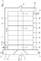
- the calibrator 2 comprises a front member 4 which includes a centrally positioned inwardly tapering cone-shaped opening 6 arranged to receive molten extruded pipe-shaped polymer.
- the front plate includes internal channels (not shown in Figure 1 ) for receiving coolant for cooling the molten polymer.
- An opening communicates with the internal channels and defines an inlet 8 for coolant and an outlet 10 communicates with the channels and provides an outlet for coolant.
- front member 4 incorporates openings (not shown in Figure 1 ) which extend from the outside and open into cone-shaped opening 6, so that a passageway extends from outside the front member to opening 6 via which passageway a vacuum may be applied to the outside of a pipe precursor present within opening 6.
- Each vacuum plate 14a is attached to the front member 4 and successive vacuum plates 14b-14h are attached to one another to define an array of vacuum plates.
- Each vacuum plate includes a circular opening 16 arranged such that the openings together define a circular cross-section opening which is axially aligned with cone-shaped opening 6 so that an extruded pipe precursor formed can pass through openings 6, 16.
- the vacuum plates 14 also incorporate openings (not shown in figure 1 ) which extend from outer cylindrical walls 18 thereof and open into circular opening 16 so that a passageway extends from outside each vacuum plate 14 to the circular opening 16 defined therein.
- the passageway enables a vacuum to be applied to a pipe precursor passing through openings 16.
- the vacuum plates 14 also include temperature control means for heating or cooling the plates and therefore heating or cooling a pipe precursor passing through the openings 16.
- vacuum plate 14a may include a fluid inlet 20 for a heating or cooling fluid and plates 14a to 14h are arranged for passage of heating/cooling fluid from inlet 20 via passageways defined in each plate 14a to 14h and out of outlet 22 in plate 14h.
- each vacuum plate may include a respective inlet and outlet, such that each respective vacuum plate 14 is served by its own heating/cooling fluid and each vacuum plate 14 can therefore be individually cooled or heated to a predetermined temperature as may be required.
- adjacent plates may be thermally insulated from one another to facilitate individual temperature control.
- the array of vacuum plates 14 is arranged within an hermetically sealed housing 23 in which a vacuum can be produced by suitable means (not shown).
- the vacuum is communicated via the passageways which extend from outside each vacuum plate 14 to the circular openings 16 so that the vacuum can be applied to a pipe precursor passing through openings 16.
- the figure 1 apparatus may be operated as follows.
- heating/cooling fluid is passed through plates 14 via the inlet 20 and outlet 22 (or via respective inlets/outlets associated with each plate); and heating/cooling fluid is passed through inlet 8 and outlet 10 of front member 4. Also, coolant is passed through front plate 4 via openings 8, 10.
- An extruded hot plastics pipe precursor of appropriate diameter and thickness defined by a pipe die fixed to the extruder is then inserted into calibrator 2 via opening 6.
- the temperature of member 4 is such as to freeze the outside wall of the pipe precursor and stop it sticking to member.
- the pipe precursor is conveyed through openings 16 in plates 14.
- the pipe precursor 16 is urged by the vacuum against the cylindrical surface defined by plates 14 to maintain its shape and the temperatures of each plate is controlled to control the rate of cooling of the pipe precursor passing through.
- the formed pipe exits the calibrator 2 as represented by arrow 24, after which it may be allowed to cool to ambient temperature.
- the heating/cooling of plates 14 may be adjusted to cool the pipe precursor at a relatively constant rate.
- a relatively slow rate may be selected so that a pipe made from a relatively fast crystallizing polymer (like polyetheretherketone) crystallises so that the crystallinity of the pipe along its extent and throughout its thickness is substantially constant.
- a pipe may therefore be made which has low or negligible residual stress.
- the calibrator may be used to deliberately form a pipe having different levels of crystallinity across its thickness.
- a pipe may be made having a skin which is relatively amorphous with the wall of the pipe inwards of the skin having relatively high crystallinity.
- FIGS 2 to 5 show parts of the calibrator of Figure 1 in more detail.
- the front member 4 includes a square cross-section plate 30 which is arranged to define one wall of housing 23. Opening 8 for receiving coolant communicates with an annular opening 32 defined within a body 34 which also defines the opening 6 for passage of the pipe precursor. The coolant is arranged to circulate within the body 34 in order to cool the surface of opening 6. Outlet 10 also communicates with opening 32 for removing coolant from the body.
- Body 34 is suitably made from a thermally conductive material, for example brass.
- the body 34 also defines a series of annular recesses 36 having mouths which open into opening 6 and which communicate with axial ports 38.
- Axial ports 38 are connected to passageways which extend to a position outside body 34 (in substantially the same manner as described with reference to Figure 5 hereinafter) so that a vacuum can be applied to opening 6 by removal of gas from opening 6 via recesses 36 and axial ports 38.
- vacuum plates 14a-j are shown which are identical. More or fewer such plates may be provided as required for any particular situation.
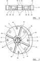
- Each vacuum plate 14 may be as shown in Figures 4 and 5 .
- the plate 14 includes ports 40, via which one plate may be secured to another.
- four radially-extending cut-outs 46 ( Figure 5 ) are defined which communicate with an annular cut-out 48 which includes eight axially-extending elongate openings 50 defined within it.
- the openings 50 communicate with an annular slot 52 defined in wall 54 which defines circular opening 16.
- an airflow passageway is defined which extends from opening 6, via slot 52, axially-extending openings 50 and cut-outs 46 to a position outside the plate 14 by means of which the vacuum can be applied to a pipe precursor arranged within opening 6.
- Plate 14 also includes an annular opening 60 defined within body 62 which communicates with radially-extending ports in the body (e.g. port 64 in Figure 5 and a diametrically opposing port not shown) for circulating coolant/heating fluid within the body 62 to cool/heat it.
- each plate 14 may have its own supply of coolant/heating fluid so that the temperature of each plate 14 may be individually controlled.
- the fluid may be caused to flow turbulently within the body.
- Plate 14 is suitably arranged so that the temperature of wall 54 is substantially the same across its surface area.
- the plates 14 are suitably arranged (e.g. by use of coolant/heating fluids of appropriate temperature) in such a way as to avoid large/abrupt temperature changes across a surface of wall 54 of an individual plate 14 and between adjacent plates 14.
- adjacent plates 14 may be arranged with the ports via which fluid is delivered to opening 6 (e.g. port 64 in Figure 5 ) and removed therefrom being staggered relative to one another and/or the inlet for fluid for a first plate 14 may be on a first side of the calibrator and the outlet may be on an opposite side, whereas the second plate 14 adjacent the first plate 14 may have its inlet for fluid on the second side and its outlet on the first side.
- inlets of adjacent plates 14 may be staggered at 45° to one another; and outlets may be arranged similarly.
- the temperature of specific regions along the calibrator may be individually controlled. More or fewer plates 14 may be included to adjust the length of the calibrator, to allow it to be used to process pipes at different speeds - e.g. a longer calibrator may be used to process pipes at lower speeds. In addition, in some embodiments, it may be desirable to use a variable vacuum (e.g. vary the level of vacuum between groups of plates), to facilitate production of a circular cross-section pipe.
- a variable vacuum e.g. vary the level of vacuum between groups of plates
- the calibrator may be of utility in the manufacture of pipes from a range of polymeric materials. It may be particularly advantageous in the manufacture of pipes from crystallisable polymeric materials having relatively high glass transition temperatures (because for such high Tg polymers, conventional water quenching ensures a too high rate of temperature drop to below Tg which generates additional stress) and/or polymeric materials which are relatively fast crystallizing. In the latter case, if such a polymeric material is cooled too quickly it will crystallise to different extents from one side of the pipe to an opposite side leading to different levels of crystallinity across the pipe, which may lead to problems as herein before described.
- PEEK polyetheretherketone
- PPS polyphenylene sulphide
- the calibrator 2 has great versatility for controlling and/or defining crystallinity in a desired manner for pipes of a range of cross-sections and wall thicknesses. Steps in manufacturing a pipe in a desired form include the following:
- water may be used to cool first member 4; and oil may be used to cool the other plates.
- 0:1 cooling may be used in some circumstances.
- a pipe having a desired level and/or arrangement of crystallinity may be manufactured.
- the calibrator 2 is readied by operating a vacuum device to extract air from within housing 23 and thereby apply a vacuum, as described, around opening 6 through which a pipe precursor is to pass. Also, heating/cooling fluid as applicable is passed through front member 4 and vacuum plates 14 so they reach equilibrium at a desired temperature. PEEK is then extruded using suitable apparatus to produce a molten pipe precursor which is introduced into cone-shaped opening 6. A melt skin is formed on the molten pipe by contact of the melt with front plate 4 which is cooled as described. The front plate defines a taper angle of about 45° which is found to be optimum for capturing the molten pipe and cooling it.
- the taper angle is the angle defined between an elongate axis of the front plate and the cone-shaped wall of the front plate). If there is insufficient cooling, the melt is too weak; and if the cooling is too great the melt sticks to the plate and the extrudate piles up on plate 4 and does not progress along the calibrator.
- the speed of introduction and/or passage of the pipe precursor into and through the calibrator may be at a constant rate, suitably in the range 0.1m/min to 10m/min.
- the pipe precursor As the pipe precursor enters opening 6, its outer surface solidifies to prevent it sticking within the opening as described above. Then the pipe precursor passes through successive plates 14, wherein it is gradually and controllably cooled, for example to maximise its crystallinity and maximize the homogeneity of its crystallinity - i.e. so that the crystallinity across the thickness of the pipe wall is substantially constant.
- the pipe On passage from the calibrator, the pipe may be at an elevated temperature and may be wound around a reel and allowed to cool to ambient temperature; or it may be cooled, for example using water, before being wound round a reel.
- the pipe passing out of the calibrator may be cut to specific lengths.
- the calibrator Once the calibrator has been set up, it may be used to manufacture a very long length of pipe (e.g. as much at 3000-4000m) having consistent properties, for example crystallinity along its extent; or it may be used to manufacture shorter lengths of pipe which have consistent properties.
- the calibrator may be particularly suitable for manufacturing pipes having an SDR (Standard Dimension Ratio) (diameter of pipe to thickness of pipe wall ratio) of greater than 6.
- SDR Standard Dimension Ratio
- the advantageous nature of pipes made as described may be illustrated by measuring the residual stress in the pipe. This may be measured as described in Example 1.
- the polymeric material closest to the bore of the pipe will cool slower than the outer surface of the pipe and consequently there may be different levels of crystallinity across the thickness of the pipe wall - crystallinity may be highest towards the centre of the pipe compared to the outer surface.
- Differences in crystallinity across a pipe wall set up different stresses in the pipe - the residual hoop stress is tensile on the pipe bore and compressive on the outer surface. This effect can be used in assessing residual stress in a pipe by cutting a ring from a pipe, forming a slit in it and assessing the split ring as it closes up in a controlled test.
- the first method is more appropriate for smaller diameter pipes (e.g. up to 20mm diameter) and the second method for larger diameter pipes (e.g. above 20mm diameter).
- Rings can be cut from the pipe and the wall thickness and original diameter (outside diameter) and average radius measured with appropriate instruments.
- the pipe is then slit in the axial direction through a radius of the pipe. The slit closes in upon itself.
- the final diameter is then measured (average of at least two positions at 90° to each other).
- Rings can be machined from a pipe and the widths, diameters and average wall thicknesses measured. The rings are then slit axially as per Method 1, and then pulled apart on a mechanical testing machine using a thin wire to apply the load (see the Hodgkinson paper referred to hereinafter).
- the load versus deformation trace shows an initial rise followed by a clear change in gradient as the ring parted passes its 'un-slit' position and begins to open out.
- ⁇ R 1.5 P 1 D ⁇ h 1 + 1 / ⁇ / Lh 2
- P 1 is the load at which the trace changes gradient and the split ring parts
- D is the external diameter
- h is the wall thickness
- L is the length of the pipe sample
- the residual stress for the 5" pipe is ⁇ 7% of the yield stress, whereas the residual stress for the 8" pipe is ⁇ 1.5% of the yield stress: the residual stress in the 5" pipe might be expected to have a significant influence on pipe performance.
Landscapes
- Engineering & Computer Science (AREA)
- Mechanical Engineering (AREA)
- General Engineering & Computer Science (AREA)
- Chemical & Material Sciences (AREA)
- Physics & Mathematics (AREA)
- Life Sciences & Earth Sciences (AREA)
- Geology (AREA)
- Mining & Mineral Resources (AREA)
- Manufacturing & Machinery (AREA)
- Thermal Sciences (AREA)
- Geochemistry & Mineralogy (AREA)
- General Life Sciences & Earth Sciences (AREA)
- Fluid Mechanics (AREA)
- Crystallography & Structural Chemistry (AREA)
- Environmental & Geological Engineering (AREA)
- Materials Engineering (AREA)
- Health & Medical Sciences (AREA)
- Chemical Kinetics & Catalysis (AREA)
- Medicinal Chemistry (AREA)
- Polymers & Plastics (AREA)
- Organic Chemistry (AREA)
- Extrusion Moulding Of Plastics Or The Like (AREA)
Claims (12)
- Rohr mit einer Länge von mindestens 1 m, das eine gemäß dem Beispiel 1 gemessene Eigenspannung von weniger als 5 MPa aufweist, vorzugsweise von weniger als 2 MPa, wobei das Rohr ein Polymermaterial umfasst, das aus der Gruppe aus Polyetheretherketon, Polyetherketon, Polyetherketonketon, Polyetherketonetherketonketon und Polyetheretherketonketon ausgewählt wurde.
- Rohr nach Anspruch 1, wobei das Rohr eine einzige Extrusion umfasst, einen im Wesentlichen konstanten Querschnitt entlang seiner gesamten Erstreckung aufweist und eine Länge von mindestens 100 m aufweist.
- Rohr nach einem der vorhergehenden Ansprüche, einen Außendurchmesser von mindestens 0,6 cm und weniger als 50 cm aufweisend.
- Rohr nach einem der vorhergehenden Ansprüche, wobei der durch die Dicke der Rohrwand dividierte Außendurchmesser des Rohres mindestens 6 beträgt.
- Rohr nach einem der vorhergehenden Ansprüche, wobei die Dicke einer das Rohr begrenzenden Wand 0,6 mm bis 6 mm beträgt.
- Rohr nach Anspruch 5, wobei die Polymerzusammensetzung weniger als 5 Gew.-% Füllstoff enthält.
- Rohr nach einem der vorhergehenden Ansprüche, wobei das Rohr Teil einer Anordnung ist, die das Rohr als einen inneren Teil umfasst, der von einem äußeren Teil umgeben ist, wobei der äußere Teil im Wesentlichen um die Gesamtheit der Umfangsaußenwand des Rohres und zum Verstärken des Rohres angeordnet ist.
- Rohr nach Anspruch 7, wobei der äußere Teil der Anordnung ein erstes Material und ein zweites Material umfasst, wobei das erste Material ein thermoplastisches oder wärmehärtbares Harz und das zweite Material ein faseriges Material umfasst.
- Rohr nach Anspruch 7 oder Anspruch 8, wobei der äußere Teil mehr als zehn übereinander liegende Schichten aufweist.
- Verfahren zur Herstellung eines Rohres nach Anspruch 1, Folgendes umfassend:(i) Auswählen einer Kaiibratorvorrichtung, die eine längliche Öffnung zum Aufnehmen eines warmextrudierten Rohres aufweist, wobei die Öffnung einen Unterdruckbeaufschlagungsbereich aufweist, der angeordnet ist, um an ein Rohr innerhalb der Öffnung einen Unterdruck anzulegen, wobei die Vorrichtung ferner mindestens zwei entlang ihrer Erstreckung voneinander beabstandete Kühlbereiche aufweist, die angeordnet sind, um ein Rohr innerhalb der Öffnung zu kühlen;(ii) Auswählen der jeweiligen Stärke des Unterdrucks, der an den Unterdruckbeaufschlagungsbereich anzulegen ist;(iii) Auswählen des jeweiligen Grads der Kühlung, der durch die Kühlbereiche anzuwenden ist;(iv) Einführen eines warmextrudierten Rohres in die längliche Öffnung in dem Kalibrator und Fördern des Rohres durch die längliche Öffnung;(v) Anlegen eines Unterdrucks an dem Rohr in dem Unterdruckbeaufschlagungsbereich; und Kühlen des Rohres in den Kühlbereichen während der Förderung des Rohres entlang der länglichen Öffnung.
- Verfahren nach Anspruch 10, das Herstellen des Rohres in einem Extruder und das Lenken von geschmolzenem Rohr von dem Extruder in den Kalibrator umfassend, um die Kristallinität des Rohres zu steuern.
- Verfahren nach Anspruch 11, das das unabhängige Steuern von mindestens zwei der Kühlbereiche umfasst, so dass die Flächen der beiden im Gebrauch das Rohr berührenden Bereiche angeordnet sind, um das Rohr unterschiedlich schnell zu kühlen, und/oder so dass die Oberflächen auf unterschiedliche Temperaturen gekühlt werden können.
Applications Claiming Priority (2)
| Application Number | Priority Date | Filing Date | Title |
|---|---|---|---|
| GBGB1102388.4A GB201102388D0 (en) | 2011-02-10 | 2011-02-10 | Pipe |
| PCT/GB2012/050267 WO2012107753A1 (en) | 2011-02-10 | 2012-02-07 | Pipe |
Publications (2)
| Publication Number | Publication Date |
|---|---|
| EP2673539A1 EP2673539A1 (de) | 2013-12-18 |
| EP2673539B1 true EP2673539B1 (de) | 2019-08-14 |
Family
ID=43859259
Family Applications (1)
| Application Number | Title | Priority Date | Filing Date |
|---|---|---|---|
| EP12704534.2A Active EP2673539B1 (de) | 2011-02-10 | 2012-02-07 | Rohr |
Country Status (7)
| Country | Link |
|---|---|
| US (2) | US10107421B2 (de) |
| EP (1) | EP2673539B1 (de) |
| BR (1) | BR112013017948B1 (de) |
| CA (1) | CA2823819C (de) |
| DK (1) | DK2673539T3 (de) |
| GB (2) | GB201102388D0 (de) |
| WO (1) | WO2012107753A1 (de) |
Families Citing this family (17)
| Publication number | Priority date | Publication date | Assignee | Title |
|---|---|---|---|---|
| WO2014130275A2 (en) | 2013-02-22 | 2014-08-28 | Ticona Llc | High performance polymer composition with improved flow properties |
| GB201322080D0 (en) * | 2013-12-13 | 2014-01-29 | Victrex Mfg Ltd | Polymeric materials |
| WO2016028613A1 (en) | 2014-08-21 | 2016-02-25 | Ticona Llc | Polyaryletherketone composition |
| US10774215B2 (en) | 2014-08-21 | 2020-09-15 | Ticona Llc | Composition containing a polyaryletherketone and low naphthenic liquid crystalline polymer |
| GB201501601D0 (en) | 2015-01-30 | 2015-03-18 | Victrex Mfg Ltd | Insulated conductors |
| EP3377555B1 (de) | 2015-11-20 | 2021-09-29 | Ticona LLC | Hochfliessende polyaryletherketonzusammensetzung |
| US11352480B2 (en) | 2016-03-18 | 2022-06-07 | Ticona Llc | Polyaryletherketone composition |
| JP2017179968A (ja) * | 2016-03-31 | 2017-10-05 | 積水化学工業株式会社 | 樹脂管 |
| JP6894545B2 (ja) * | 2016-03-31 | 2021-06-30 | 積水化学工業株式会社 | 側溝更生方法 |
| CN109228245A (zh) * | 2017-07-10 | 2019-01-18 | 天津市禹神建筑防水材料有限公司 | 一种高分子膜防水卷材风冷装置 |
| FR3074184B1 (fr) | 2017-11-27 | 2020-07-24 | Arkema France | Utilisation de pekk pour la fabrication de pieces a faible permeabilite gazeuse |
| US11118053B2 (en) | 2018-03-09 | 2021-09-14 | Ticona Llc | Polyaryletherketone/polyarylene sulfide composition |
| GB201905431D0 (en) * | 2019-04-17 | 2019-05-29 | Victrex Mfg Ltd | Improved pipe and method of production |
| GB201905432D0 (en) | 2019-04-17 | 2019-05-29 | Victrex Mfg Ltd | Long pipes with reduced defects and method of production |
| EP3976336B1 (de) | 2019-05-31 | 2026-01-28 | Victrex Manufacturing Limited | Rohrherstellung |
| CN112895374B (zh) * | 2021-02-07 | 2023-04-25 | 云南长宜科技有限公司 | 一种气流单元的制备方法及装置 |
| GB202110832D0 (en) | 2021-07-28 | 2021-09-08 | Victrex Mfg Ltd | Pipe and method of production |
Family Cites Families (13)
| Publication number | Priority date | Publication date | Assignee | Title |
|---|---|---|---|---|
| SU1412985A1 (ru) | 1986-09-18 | 1988-07-30 | Украинский Научно-Исследовательский Институт По Разработке Машин И Оборудования Для Переработки Пластмасс,Резины И Искусственной Кожи | Способ охлаждени полимерных погонажных трубчатых изделий |
| US4826906A (en) | 1987-06-22 | 1989-05-02 | Kureha Kagaku Kogyo K.K. | Poly(arylene thioether-ketone) compositions improved in both melt stability and crystallinity |
| US5286814A (en) | 1988-06-13 | 1994-02-15 | Kureha Kagaku Kogyo K. K. | Heat-resistant stretched film and production process thereof |
| JPH0688354B2 (ja) | 1988-08-24 | 1994-11-09 | フクビ化学工業株式会社 | Peek樹脂パイプの製造方法 |
| US5381511A (en) * | 1993-06-02 | 1995-01-10 | W. L. Gore & Associates, Inc. | Flexible electrically heatable hose |
| AT408532B (de) | 1996-01-30 | 2001-12-27 | Greiner & Soehne C A | Formgebungseinrichtung für eine extrusionsanlage |
| DE59800721D1 (de) * | 1998-02-27 | 2001-06-21 | Koemmerling Kunststoff Gmbh | Kalibriervorrichtung |
| US6065754A (en) | 1998-04-15 | 2000-05-23 | General Electric Co. | Uniform clearance, temperature responsive, variable packing ring |
| WO2001098700A1 (en) | 2000-06-22 | 2001-12-27 | Idemitsu Petrochemical Co., Ltd. | Pipe made of ethylene polymer |
| AT413804B (de) | 2004-08-06 | 2006-06-15 | Gruber & Co Group Gmbh | Vorrichtung zum kalibrieren eines extrudierten kunststoffprofils |
| US8813332B2 (en) * | 2005-08-26 | 2014-08-26 | Victrex Manufacturing Limited | Polymeric materials |
| GB0517385D0 (en) | 2005-08-26 | 2005-10-05 | Victrex Mfg Ltd | Polymeric materials |
| GB0818967D0 (en) | 2008-10-16 | 2008-11-26 | Victrex Mfg Ltd | Polymeric materials |
-
2011
- 2011-02-10 GB GBGB1102388.4A patent/GB201102388D0/en not_active Ceased
-
2012
- 2012-02-07 WO PCT/GB2012/050267 patent/WO2012107753A1/en not_active Ceased
- 2012-02-07 EP EP12704534.2A patent/EP2673539B1/de active Active
- 2012-02-07 CA CA2823819A patent/CA2823819C/en active Active
- 2012-02-07 US US13/983,598 patent/US10107421B2/en active Active
- 2012-02-07 BR BR112013017948-1A patent/BR112013017948B1/pt active IP Right Grant
- 2012-02-07 DK DK12704534.2T patent/DK2673539T3/da active
- 2012-02-08 GB GB1202135.8A patent/GB2488212A/en not_active Withdrawn
-
2018
- 2018-10-19 US US16/165,795 patent/US11236847B2/en active Active
Non-Patent Citations (1)
| Title |
|---|
| None * |
Also Published As
| Publication number | Publication date |
|---|---|
| DK2673539T3 (da) | 2019-10-21 |
| BR112013017948B1 (pt) | 2020-10-13 |
| EP2673539A1 (de) | 2013-12-18 |
| BR112013017948A2 (pt) | 2018-09-25 |
| US11236847B2 (en) | 2022-02-01 |
| WO2012107753A1 (en) | 2012-08-16 |
| GB2488212A (en) | 2012-08-22 |
| US20190120410A1 (en) | 2019-04-25 |
| GB201202135D0 (en) | 2012-03-21 |
| GB201102388D0 (en) | 2011-03-30 |
| CA2823819C (en) | 2022-07-12 |
| US10107421B2 (en) | 2018-10-23 |
| US20130306188A1 (en) | 2013-11-21 |
| CA2823819A1 (en) | 2012-08-16 |
Similar Documents
| Publication | Publication Date | Title |
|---|---|---|
| US11236847B2 (en) | Pipe | |
| EP2550154B1 (de) | Verfharen zur herstellung eines verebundrohrs und verbundrohr | |
| Stevens et al. | Extruder principles and operation | |
| KR100936729B1 (ko) | 관형상 열가소성 필름의 길이방향 배향 | |
| AU2012242983A1 (en) | Umbilical for use in subsea applications | |
| EP1453647B1 (de) | Verfahren zur herstellung einer dünnen platte aus polypropylen | |
| Vatandaş et al. | Mechanical performances of continuous carbon fiber reinforced PEEK (polyether ether ketone) composites printed in a vacuum environment | |
| US20150017416A1 (en) | Composite Tapes and Rods Having Embedded Sensing Elements | |
| US4942070A (en) | Extruded conduits and method of making the same | |
| EP1989042A1 (de) | Rohrverbindung | |
| OA16503A (en) | Pipe. | |
| WO2017046599A1 (en) | Polymeric materials | |
| US20160201403A1 (en) | Composite Sucker Rod Assemblies | |
| EP4377059B1 (de) | Rohr und verfahren zur herstellung | |
| EP3956133A1 (de) | Lange rohre mit reduzierten defekten und herstellungsverfahren | |
| BR102012003478A2 (pt) | Processo para produção de barras | |
| EP3956381A1 (de) | Verbessertes rohr und verfahren zu dessen herstellung | |
| CN115923209B (zh) | 一种连续纤维布/uhmwpe复合材料及其双层共挤成型工艺 | |
| BR112021019085B1 (pt) | Tubo aperfeiçoado e processo para produzir um tubo | |
| Rosato | Pipe and tube | |
| EP1990176A1 (de) | Verlängerbare Schmelzzuführungsleitung | |
| JP2017160316A (ja) | 炭素繊維複合材料およびその製造方法 | |
| Maeger et al. | Polyethylene Pipe Extrusion | |
| KR20190088619A (ko) | 폴리에테르 에테르 케톤 필름 제조장치 | |
| HK1068846B (en) | Process for fabricating polypropylene sheet |
Legal Events
| Date | Code | Title | Description |
|---|---|---|---|
| PUAI | Public reference made under article 153(3) epc to a published international application that has entered the european phase |
Free format text: ORIGINAL CODE: 0009012 |
|
| 17P | Request for examination filed |
Effective date: 20130802 |
|
| AK | Designated contracting states |
Kind code of ref document: A1 Designated state(s): AL AT BE BG CH CY CZ DE DK EE ES FI FR GB GR HR HU IE IS IT LI LT LU LV MC MK MT NL NO PL PT RO RS SE SI SK SM TR |
|
| DAX | Request for extension of the european patent (deleted) | ||
| STAA | Information on the status of an ep patent application or granted ep patent |
Free format text: STATUS: EXAMINATION IS IN PROGRESS |
|
| 17Q | First examination report despatched |
Effective date: 20161118 |
|
| REG | Reference to a national code |
Ref country code: DE Ref legal event code: R079 Ref document number: 602012062914 Country of ref document: DE Free format text: PREVIOUS MAIN CLASS: F16L0011060000 Ipc: C08J0005000000 |
|
| GRAP | Despatch of communication of intention to grant a patent |
Free format text: ORIGINAL CODE: EPIDOSNIGR1 |
|
| STAA | Information on the status of an ep patent application or granted ep patent |
Free format text: STATUS: GRANT OF PATENT IS INTENDED |
|
| RIC1 | Information provided on ipc code assigned before grant |
Ipc: C08J 5/00 20060101AFI20190123BHEP Ipc: E21B 17/01 20060101ALI20190123BHEP Ipc: B29C 71/02 20060101ALI20190123BHEP Ipc: C08L 71/10 20060101ALN20190123BHEP Ipc: F16L 11/06 20060101ALI20190123BHEP |
|
| RIC1 | Information provided on ipc code assigned before grant |
Ipc: C08J 5/00 20060101AFI20190207BHEP Ipc: E21B 17/01 20060101ALI20190207BHEP Ipc: C08L 71/10 20060101ALN20190207BHEP Ipc: F16L 11/06 20060101ALI20190207BHEP Ipc: B29C 71/02 20060101ALI20190207BHEP |
|
| INTG | Intention to grant announced |
Effective date: 20190222 |
|
| GRAS | Grant fee paid |
Free format text: ORIGINAL CODE: EPIDOSNIGR3 |
|
| GRAA | (expected) grant |
Free format text: ORIGINAL CODE: 0009210 |
|
| STAA | Information on the status of an ep patent application or granted ep patent |
Free format text: STATUS: THE PATENT HAS BEEN GRANTED |
|
| AK | Designated contracting states |
Kind code of ref document: B1 Designated state(s): AL AT BE BG CH CY CZ DE DK EE ES FI FR GB GR HR HU IE IS IT LI LT LU LV MC MK MT NL NO PL PT RO RS SE SI SK SM TR |
|
| REG | Reference to a national code |
Ref country code: GB Ref legal event code: FG4D |
|
| REG | Reference to a national code |
Ref country code: CH Ref legal event code: EP Ref country code: AT Ref legal event code: REF Ref document number: 1166947 Country of ref document: AT Kind code of ref document: T Effective date: 20190815 |
|
| REG | Reference to a national code |
Ref country code: NL Ref legal event code: FP |
|
| REG | Reference to a national code |
Ref country code: DE Ref legal event code: R096 Ref document number: 602012062914 Country of ref document: DE |
|
| REG | Reference to a national code |
Ref country code: IE Ref legal event code: FG4D |
|
| REG | Reference to a national code |
Ref country code: DK Ref legal event code: T3 Effective date: 20191017 |
|
| REG | Reference to a national code |
Ref country code: NO Ref legal event code: T2 Effective date: 20190814 |
|
| REG | Reference to a national code |
Ref country code: LT Ref legal event code: MG4D |
|
| PG25 | Lapsed in a contracting state [announced via postgrant information from national office to epo] |
Ref country code: LT Free format text: LAPSE BECAUSE OF FAILURE TO SUBMIT A TRANSLATION OF THE DESCRIPTION OR TO PAY THE FEE WITHIN THE PRESCRIBED TIME-LIMIT Effective date: 20190814 Ref country code: HR Free format text: LAPSE BECAUSE OF FAILURE TO SUBMIT A TRANSLATION OF THE DESCRIPTION OR TO PAY THE FEE WITHIN THE PRESCRIBED TIME-LIMIT Effective date: 20190814 Ref country code: SE Free format text: LAPSE BECAUSE OF FAILURE TO SUBMIT A TRANSLATION OF THE DESCRIPTION OR TO PAY THE FEE WITHIN THE PRESCRIBED TIME-LIMIT Effective date: 20190814 Ref country code: FI Free format text: LAPSE BECAUSE OF FAILURE TO SUBMIT A TRANSLATION OF THE DESCRIPTION OR TO PAY THE FEE WITHIN THE PRESCRIBED TIME-LIMIT Effective date: 20190814 Ref country code: PT Free format text: LAPSE BECAUSE OF FAILURE TO SUBMIT A TRANSLATION OF THE DESCRIPTION OR TO PAY THE FEE WITHIN THE PRESCRIBED TIME-LIMIT Effective date: 20191216 Ref country code: BG Free format text: LAPSE BECAUSE OF FAILURE TO SUBMIT A TRANSLATION OF THE DESCRIPTION OR TO PAY THE FEE WITHIN THE PRESCRIBED TIME-LIMIT Effective date: 20191114 |
|
| REG | Reference to a national code |
Ref country code: AT Ref legal event code: MK05 Ref document number: 1166947 Country of ref document: AT Kind code of ref document: T Effective date: 20190814 |
|
| PG25 | Lapsed in a contracting state [announced via postgrant information from national office to epo] |
Ref country code: IS Free format text: LAPSE BECAUSE OF FAILURE TO SUBMIT A TRANSLATION OF THE DESCRIPTION OR TO PAY THE FEE WITHIN THE PRESCRIBED TIME-LIMIT Effective date: 20191214 Ref country code: RS Free format text: LAPSE BECAUSE OF FAILURE TO SUBMIT A TRANSLATION OF THE DESCRIPTION OR TO PAY THE FEE WITHIN THE PRESCRIBED TIME-LIMIT Effective date: 20190814 Ref country code: GR Free format text: LAPSE BECAUSE OF FAILURE TO SUBMIT A TRANSLATION OF THE DESCRIPTION OR TO PAY THE FEE WITHIN THE PRESCRIBED TIME-LIMIT Effective date: 20191115 Ref country code: AL Free format text: LAPSE BECAUSE OF FAILURE TO SUBMIT A TRANSLATION OF THE DESCRIPTION OR TO PAY THE FEE WITHIN THE PRESCRIBED TIME-LIMIT Effective date: 20190814 Ref country code: LV Free format text: LAPSE BECAUSE OF FAILURE TO SUBMIT A TRANSLATION OF THE DESCRIPTION OR TO PAY THE FEE WITHIN THE PRESCRIBED TIME-LIMIT Effective date: 20190814 Ref country code: ES Free format text: LAPSE BECAUSE OF FAILURE TO SUBMIT A TRANSLATION OF THE DESCRIPTION OR TO PAY THE FEE WITHIN THE PRESCRIBED TIME-LIMIT Effective date: 20190814 |
|
| PG25 | Lapsed in a contracting state [announced via postgrant information from national office to epo] |
Ref country code: TR Free format text: LAPSE BECAUSE OF FAILURE TO SUBMIT A TRANSLATION OF THE DESCRIPTION OR TO PAY THE FEE WITHIN THE PRESCRIBED TIME-LIMIT Effective date: 20190814 |
|
| PG25 | Lapsed in a contracting state [announced via postgrant information from national office to epo] |
Ref country code: AT Free format text: LAPSE BECAUSE OF FAILURE TO SUBMIT A TRANSLATION OF THE DESCRIPTION OR TO PAY THE FEE WITHIN THE PRESCRIBED TIME-LIMIT Effective date: 20190814 Ref country code: PL Free format text: LAPSE BECAUSE OF FAILURE TO SUBMIT A TRANSLATION OF THE DESCRIPTION OR TO PAY THE FEE WITHIN THE PRESCRIBED TIME-LIMIT Effective date: 20190814 Ref country code: RO Free format text: LAPSE BECAUSE OF FAILURE TO SUBMIT A TRANSLATION OF THE DESCRIPTION OR TO PAY THE FEE WITHIN THE PRESCRIBED TIME-LIMIT Effective date: 20190814 Ref country code: EE Free format text: LAPSE BECAUSE OF FAILURE TO SUBMIT A TRANSLATION OF THE DESCRIPTION OR TO PAY THE FEE WITHIN THE PRESCRIBED TIME-LIMIT Effective date: 20190814 Ref country code: IT Free format text: LAPSE BECAUSE OF FAILURE TO SUBMIT A TRANSLATION OF THE DESCRIPTION OR TO PAY THE FEE WITHIN THE PRESCRIBED TIME-LIMIT Effective date: 20190814 |
|
| PG25 | Lapsed in a contracting state [announced via postgrant information from national office to epo] |
Ref country code: SM Free format text: LAPSE BECAUSE OF FAILURE TO SUBMIT A TRANSLATION OF THE DESCRIPTION OR TO PAY THE FEE WITHIN THE PRESCRIBED TIME-LIMIT Effective date: 20190814 Ref country code: IS Free format text: LAPSE BECAUSE OF FAILURE TO SUBMIT A TRANSLATION OF THE DESCRIPTION OR TO PAY THE FEE WITHIN THE PRESCRIBED TIME-LIMIT Effective date: 20200224 Ref country code: CZ Free format text: LAPSE BECAUSE OF FAILURE TO SUBMIT A TRANSLATION OF THE DESCRIPTION OR TO PAY THE FEE WITHIN THE PRESCRIBED TIME-LIMIT Effective date: 20190814 Ref country code: SK Free format text: LAPSE BECAUSE OF FAILURE TO SUBMIT A TRANSLATION OF THE DESCRIPTION OR TO PAY THE FEE WITHIN THE PRESCRIBED TIME-LIMIT Effective date: 20190814 |
|
| REG | Reference to a national code |
Ref country code: DE Ref legal event code: R097 Ref document number: 602012062914 Country of ref document: DE |
|
| PLBE | No opposition filed within time limit |
Free format text: ORIGINAL CODE: 0009261 |
|
| STAA | Information on the status of an ep patent application or granted ep patent |
Free format text: STATUS: NO OPPOSITION FILED WITHIN TIME LIMIT |
|
| PG2D | Information on lapse in contracting state deleted |
Ref country code: IS |
|
| 26N | No opposition filed |
Effective date: 20200603 |
|
| PG25 | Lapsed in a contracting state [announced via postgrant information from national office to epo] |
Ref country code: SI Free format text: LAPSE BECAUSE OF FAILURE TO SUBMIT A TRANSLATION OF THE DESCRIPTION OR TO PAY THE FEE WITHIN THE PRESCRIBED TIME-LIMIT Effective date: 20190814 |
|
| REG | Reference to a national code |
Ref country code: CH Ref legal event code: PL |
|
| REG | Reference to a national code |
Ref country code: BE Ref legal event code: MM Effective date: 20200229 |
|
| PG25 | Lapsed in a contracting state [announced via postgrant information from national office to epo] |
Ref country code: MC Free format text: LAPSE BECAUSE OF FAILURE TO SUBMIT A TRANSLATION OF THE DESCRIPTION OR TO PAY THE FEE WITHIN THE PRESCRIBED TIME-LIMIT Effective date: 20190814 Ref country code: LU Free format text: LAPSE BECAUSE OF NON-PAYMENT OF DUE FEES Effective date: 20200207 |
|
| PG25 | Lapsed in a contracting state [announced via postgrant information from national office to epo] |
Ref country code: CH Free format text: LAPSE BECAUSE OF NON-PAYMENT OF DUE FEES Effective date: 20200229 Ref country code: LI Free format text: LAPSE BECAUSE OF NON-PAYMENT OF DUE FEES Effective date: 20200229 |
|
| PG25 | Lapsed in a contracting state [announced via postgrant information from national office to epo] |
Ref country code: IE Free format text: LAPSE BECAUSE OF NON-PAYMENT OF DUE FEES Effective date: 20200207 |
|
| PG25 | Lapsed in a contracting state [announced via postgrant information from national office to epo] |
Ref country code: BE Free format text: LAPSE BECAUSE OF NON-PAYMENT OF DUE FEES Effective date: 20200229 |
|
| PG25 | Lapsed in a contracting state [announced via postgrant information from national office to epo] |
Ref country code: MT Free format text: LAPSE BECAUSE OF FAILURE TO SUBMIT A TRANSLATION OF THE DESCRIPTION OR TO PAY THE FEE WITHIN THE PRESCRIBED TIME-LIMIT Effective date: 20190814 Ref country code: CY Free format text: LAPSE BECAUSE OF FAILURE TO SUBMIT A TRANSLATION OF THE DESCRIPTION OR TO PAY THE FEE WITHIN THE PRESCRIBED TIME-LIMIT Effective date: 20190814 |
|
| PG25 | Lapsed in a contracting state [announced via postgrant information from national office to epo] |
Ref country code: MK Free format text: LAPSE BECAUSE OF FAILURE TO SUBMIT A TRANSLATION OF THE DESCRIPTION OR TO PAY THE FEE WITHIN THE PRESCRIBED TIME-LIMIT Effective date: 20190814 |
|
| P01 | Opt-out of the competence of the unified patent court (upc) registered |
Effective date: 20230428 |
|
| PGFP | Annual fee paid to national office [announced via postgrant information from national office to epo] |
Ref country code: DK Payment date: 20250224 Year of fee payment: 14 |
|
| PGFP | Annual fee paid to national office [announced via postgrant information from national office to epo] |
Ref country code: NO Payment date: 20250221 Year of fee payment: 14 |
|
| PGFP | Annual fee paid to national office [announced via postgrant information from national office to epo] |
Ref country code: NL Payment date: 20260218 Year of fee payment: 15 |
|
| PGFP | Annual fee paid to national office [announced via postgrant information from national office to epo] |
Ref country code: GB Payment date: 20260219 Year of fee payment: 15 |
|
| PGFP | Annual fee paid to national office [announced via postgrant information from national office to epo] |
Ref country code: DE Payment date: 20260218 Year of fee payment: 15 |
|
| PGFP | Annual fee paid to national office [announced via postgrant information from national office to epo] |
Ref country code: FR Payment date: 20260218 Year of fee payment: 15 |