EP2673522B1 - Dämpfungseinrichtung - Google Patents
Dämpfungseinrichtung Download PDFInfo
- Publication number
- EP2673522B1 EP2673522B1 EP12712552.4A EP12712552A EP2673522B1 EP 2673522 B1 EP2673522 B1 EP 2673522B1 EP 12712552 A EP12712552 A EP 12712552A EP 2673522 B1 EP2673522 B1 EP 2673522B1
- Authority
- EP
- European Patent Office
- Prior art keywords
- sound
- damping
- absorber
- damping element
- housing
- Prior art date
- Legal status (The legal status is an assumption and is not a legal conclusion. Google has not performed a legal analysis and makes no representation as to the accuracy of the status listed.)
- Not-in-force
Links
- 238000013016 damping Methods 0.000 title claims description 52
- 239000006096 absorbing agent Substances 0.000 claims description 32
- 239000012530 fluid Substances 0.000 claims description 12
- 239000011148 porous material Substances 0.000 claims description 8
- 230000009467 reduction Effects 0.000 claims description 7
- 238000003466 welding Methods 0.000 description 5
- 230000006870 function Effects 0.000 description 4
- 230000010354 integration Effects 0.000 description 3
- 238000009423 ventilation Methods 0.000 description 3
- 230000008901 benefit Effects 0.000 description 2
- 238000013022 venting Methods 0.000 description 2
- 230000009471 action Effects 0.000 description 1
- 230000003321 amplification Effects 0.000 description 1
- 238000004458 analytical method Methods 0.000 description 1
- 238000010276 construction Methods 0.000 description 1
- 230000008878 coupling Effects 0.000 description 1
- 238000010168 coupling process Methods 0.000 description 1
- 238000005859 coupling reaction Methods 0.000 description 1
- 230000001419 dependent effect Effects 0.000 description 1
- 230000000694 effects Effects 0.000 description 1
- 239000000463 material Substances 0.000 description 1
- 238000003199 nucleic acid amplification method Methods 0.000 description 1
- 230000010355 oscillation Effects 0.000 description 1
- 238000005381 potential energy Methods 0.000 description 1
- 230000001629 suppression Effects 0.000 description 1
Images

Classifications
-
- F—MECHANICAL ENGINEERING; LIGHTING; HEATING; WEAPONS; BLASTING
- F16—ENGINEERING ELEMENTS AND UNITS; GENERAL MEASURES FOR PRODUCING AND MAINTAINING EFFECTIVE FUNCTIONING OF MACHINES OR INSTALLATIONS; THERMAL INSULATION IN GENERAL
- F16D—COUPLINGS FOR TRANSMITTING ROTATION; CLUTCHES; BRAKES
- F16D48/00—External control of clutches
- F16D48/02—Control by fluid pressure
-
- F—MECHANICAL ENGINEERING; LIGHTING; HEATING; WEAPONS; BLASTING
- F15—FLUID-PRESSURE ACTUATORS; HYDRAULICS OR PNEUMATICS IN GENERAL
- F15B—SYSTEMS ACTING BY MEANS OF FLUIDS IN GENERAL; FLUID-PRESSURE ACTUATORS, e.g. SERVOMOTORS; DETAILS OF FLUID-PRESSURE SYSTEMS, NOT OTHERWISE PROVIDED FOR
- F15B21/00—Common features of fluid actuator systems; Fluid-pressure actuator systems or details thereof, not covered by any other group of this subclass
- F15B21/008—Reduction of noise or vibration
-
- F—MECHANICAL ENGINEERING; LIGHTING; HEATING; WEAPONS; BLASTING
- F16—ENGINEERING ELEMENTS AND UNITS; GENERAL MEASURES FOR PRODUCING AND MAINTAINING EFFECTIVE FUNCTIONING OF MACHINES OR INSTALLATIONS; THERMAL INSULATION IN GENERAL
- F16D—COUPLINGS FOR TRANSMITTING ROTATION; CLUTCHES; BRAKES
- F16D25/00—Fluid-actuated clutches
- F16D25/08—Fluid-actuated clutches with fluid-actuated member not rotating with a clutching member
-
- F—MECHANICAL ENGINEERING; LIGHTING; HEATING; WEAPONS; BLASTING
- F16—ENGINEERING ELEMENTS AND UNITS; GENERAL MEASURES FOR PRODUCING AND MAINTAINING EFFECTIVE FUNCTIONING OF MACHINES OR INSTALLATIONS; THERMAL INSULATION IN GENERAL
- F16D—COUPLINGS FOR TRANSMITTING ROTATION; CLUTCHES; BRAKES
- F16D25/00—Fluid-actuated clutches
- F16D25/12—Details not specific to one of the before-mentioned types
-
- F—MECHANICAL ENGINEERING; LIGHTING; HEATING; WEAPONS; BLASTING
- F16—ENGINEERING ELEMENTS AND UNITS; GENERAL MEASURES FOR PRODUCING AND MAINTAINING EFFECTIVE FUNCTIONING OF MACHINES OR INSTALLATIONS; THERMAL INSULATION IN GENERAL
- F16D—COUPLINGS FOR TRANSMITTING ROTATION; CLUTCHES; BRAKES
- F16D48/00—External control of clutches
- F16D48/02—Control by fluid pressure
- F16D2048/0215—Control by fluid pressure for damping of pulsations within the fluid system
Definitions
- the invention relates to a damping device for damping undesired pressure fluctuations in a hydraulic path, in particular for a clutch actuation.
- a damping device is likewise arranged on at least one branch within a hydraulic path for coupling actuation.
- the branch is formed from a Winkeistecker with two preferably perpendicular to each other plugs executed.
- the connection of the damping device with one of these plugs is secured in the axial direction by means of a fastening element, wherein the damping device is formed by a throttle plug partially closing the outlet opening of this plug, which is enveloped by a container provided with an insert.
- One way of solving this problem can be to increase the rigidity of the can higher than 4mm 3 / bar, but such constructive action is not possible with the current solutions.
- a reduction of the wall thickness or enlargement of the surface leads to high load in the material (in particular for the welding).
- a damping device for damping unwanted pressure fluctuations in a hydraulic path in particular for a clutch actuation, wherein a master cylinder and a slave cylinder are interconnected by means of a pressure line through which fluid flows, is known from a still unpublished solution, wherein a damper, based on the Helmholtz -Resonator principle, use that has functional elements that are integrated into the hydraulic system.
- the aforementioned absorbers always ensure a very effective effect with respect to vibration reduction in the selected, but limited, frequency range. He always has a relatively narrow band and can for example delete a resonance.
- the stiffness of the absorber determines the bandwidth and is a compromise between the permissible pedal travel losses and the desired functionality.
- Known silencers such as those used in car exhaust systems and other areas, are capable of damping all-vibrations and thus can completely cancel resonances.
- porous materials are used, for example, to improve the sound damping properties (see DE 60 2004 008 774 T2 ).
- the object of the invention is to develop a damping device for damping undesired pressure fluctuations in a hydraulic path, in particular for a clutch actuation, which enables a broadband vibration damping and reduces or avoids pedal travel losses.
- the damping device for damping undesired pressure fluctuations in a hydraulic path is used in particular for a clutch application, wherein a master cylinder and a slave cylinder are connected to each other by means of a fluid-flowed pressure line, using a arranged in the hydraulic path absorber, which has a housing with a through hole for the fluid, wherein according to the invention with the absorber, a sound-damping element is combined.
- the sound-absorbing element of porous material as used for example for mufflers in exhaust systems.
- the sound-damping element is integrated into the through-opening of the absorber, with one or more flow-through channels preferably extending in the flow direction through the porous sound-damping element.
- the absorber is advantageously arranged coaxially to the pressure line and the sound-damping element is in particular cylindrical and also arranged coaxially to the pressure line in the housing of the absorber, wherein at least one flow-through of the sound-absorbing Element centric and coaxial leads to the pressure line through the sound-absorbing element.
- the pores of the sound-absorbing member are preferably formed open and also communicate with each other, so that it is possible that the fluid flows with the appropriate pressure not only through the / the flow passages, but also through the porous material of the sound-absorbing element.
- the flow resistance is determined by the number and the cross section of the flow channels and by the number and size of pores. In particular, the flow channels serve to minimize the resistance of the damper during normal pedal operation.
- the sound-damping element is preferably made of porous material which is self-supporting.
- the sound-damping element is arranged in a support body / cage, wherein the support body / cage, the porous region of the sound-absorbing element at least circumferentially partially or completely sheathed.
- the sound-absorbing element is axially fixed between two stops within the housing.
- the sound-absorbing element is followed by a Tilgerzutechnisch in the form of a press-fit part.
- the sound-absorbing porous medium is positioned in the housing and then the Tilgerzu effet mounted / pressed.
- the housing cover is preferably connected to the housing by welding, for example spin welding.
- the press-in part has, in the direction of the cover, a flow distributor which leads the fluid radially outward from the passage opening of the connection in the cover.
- an anti-rotation is provided, preferably in the form of a flattening on Einpressteil corresponding to a corresponding surface of the housing.
- the housing has at its end opposite the first terminal a second connection for the pressure line, with which it is fixed in position fixable to the pressure line, so that the housing can be integrated into the pressure line, that the relative position of the supply line to the pressure line known and is adjustable so that the supply line is oriented upwards to ensure venting.
- the Einpressteil has a flow distributor, through which fluid to the highest point of the Tilgers arrive.
- the new and inventive construction utilizes the known coaxial arrangement of the absorber in combination with a sound attenuating element.
- the vibration energy should be effectively converted into heat. This is ensured by the solution according to the invention.
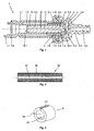
- FIG. 1 shows a longitudinal section of a damper 1, which has a housing 1.1. On the representation of seals and retaining clips has been omitted.
- a sound-damping element 10 is arranged from a porous medium, which is cylindrical and has a central flow channel 11.
- the sound-damping element 10 rests with its first end 12.1, which projects into the housing 1.1, on a radial first stop 13 in the housing, which is formed by a radially inwardly facing diameter reduction of the passage opening 1.3.
- the second end face 12.2 of the sound-absorbing Element 10 closes off approximately with the first end 1.4 of the housing 1.1, from whose direction the annular space 1.2 is introduced.
- a press-in part 2 was provided, which is pressed into the annular space 1.2 and with a radially inwardly pointing (not designated) paragraph on an end face at the first end 1.4 of the housing 1.1 and at the second front end 12.2 of the sound-absorbing Element 10 is applied and forms a second stop 14 for this.
- a cover 3 is fixed, which has a connection 3.1 with a through opening 3.2 for connection to a pressure line, not shown.
- the press-in part 2 is provided on its outer circumference with a groove which forms a feed line 2.1 to the annular space 1.2. Radially outside the supply line 2.1 by the housing 1.1 ver, closed. Furthermore, the press-in part 2 has a flow distributor 2.2, which is designed in the form of a radially inwardly facing wall which has a central opening 2.3, which forms a passage from the passage opening 3.2 of the lid 3 to the central passage opening 1.3 of the housing 1.1. Between the inner wall of the lid 3 and the front end of the press-in part 2 facing it, a space 4 through which fluid can flow is formed.
- the press-in part 2 has at its end opposite the flow distributor 2.2 a flattening 2.5, which corresponds to a first flattening 1.5 on the housing 1.1. At its second end 1.6, the absorber 1 is also connected to the pressure line (not shown). In order to ensure that the supply line 2.1 of the press-in part 2 is always at the top (for ventilation), second flattenings 1.7, which serve to fix the position, are also provided at the second end 1.6. Thus, the relative position of the supply line 2.1 to the main line can be determined and aligned. For ventilation, the supply line 2.1 of the press-in part 2 must always be aligned upward.
- the cover 3 has on the inside a plurality of pins 3.5, which extend in the axial direction and is designed cone-shaped or hemispherical, so that this space is used in conjunction with the flow distributor 2.2 of the press-in part 2 for flow distribution.
- the coaxial arrangement of the absorber 1 in the pressure line allows a slim design and easy integration into the pressure line.
- the lid 3 is preferably connected to the housing 1.1 by friction welding.
- the friction welding is carried out by adapted geometry of the housing 1.1 and the cover 3.
- the cover 3 has an end-side annular projection 3.4, which engages in an end-side annular groove 1.10 of the housing 1.1.
- FIG. 2 The longitudinal section through a cylindrical sound-damping element 10 with a circumferential support body 15 and a centric flow opening 11 is in FIG. 2 shown.
- the support body 15 forms a reverberant and rigid wall and ensures that a very porous medium, which does not have its own supporting force, is ever philgbar in the housing. It is also possible to additionally provide the flow opening or the first end 12.1 and the second end 12.2 in addition to a support body.
- the three-dimensional hollow cylindrical press-fit part 2 is in FIG. 3 shown. From this, the groove-like feed line 2.1, the opening 2.3 and serving for fixing position flattening 2.5 can be seen. By the supply line 2.1 in the form of a groove, a small outer diameter can be realized. In the assembled state, the closed by the housing 1.1 groove then acts as a hole, since only the cross-section is important for the function.
- the memory / absorber 1 has the advantage that the damping properties of the absorber 1 are considerably improved compared to conventional solutions by the very simple measure in the form of the integration of a sound-damping element 10 in the form of a cylindrical porous member, which is apparent from Figure 5.
- FIG. 4 shows a comparison of the pressure in the master cylinder as a function of the frequency in the hydraulic path.
- the thin dotted line represents the pressure without absorber, the dashed line the damping with a absorber.
- the dash-dot line the damping with a damper and the solid line the damping with the inventive combination damper and damper. It can be seen that with the latter solution according to the invention the best vibration damping results are obtained.
- the damping device is integrated into the hydraulic track.
- This new coaxial solution consists of only four parts, namely a housing 1 (memory), in which the vibration-damping element 10 and the press-in part 2 are arranged and the lid 3 and is therefore simple and inexpensive to produce
- the vibration damping element 10 may not be integrated into the absorber, but may be arranged in front of and / or thereafter.
Landscapes
- Engineering & Computer Science (AREA)
- General Engineering & Computer Science (AREA)
- Mechanical Engineering (AREA)
- Physics & Mathematics (AREA)
- Fluid Mechanics (AREA)
- Chemical & Material Sciences (AREA)
- Analytical Chemistry (AREA)
- Hydraulic Clutches, Magnetic Clutches, Fluid Clutches, And Fluid Joints (AREA)
Description
- Die Erfindung betrifft eine Dämpfungseinrichtung zur Dämpfung von unerwünschten Druckschwankungen in einer hydraulischen Strecke, insbesondere für eine Kupplungsbetätigung.
- Aus der Druckschrift
DE 10 2008 003 991 A1 ist eine Lösung zur Unterdrückung von Eigenresonanzen in einer hydraulischen Strecke bekannt, bei welcher dazu ein besonders ausgestalteter Helmholtz-Resonator verwendet wird. Dieser besteht aus einem Leitungsstück, das mit einem von diesem abzweigenden Behälter verbunden ist. Die Verzweigung, die aus einem T-Stück gebildet wird, ermöglicht, den Helmholtz-Resonator mit dem Ausrücksystem zu verknüpfen. Das Ausrücksystem besteht im Wesentlichen aus einem Geber- und einem Nehmerzylinder, die mittels einer Druckleitung miteinander verbunden sind. Die Druckleitung ist ihrem Volumen entsprechend mit Fluidmasse befüllt und fungiert somit als Speicher für die kinetische Energie. Der als Druckspeicher fungierende Behälter hat die Funktion eines federnden Elements mit einer bestimmten hydraulischen Kapazität. Er speichert damit die potentielle Energie. Die Abmessungen der Druckleitung und die hydraulische Kapazität des Behälters sollen nach der erfinderischen Lösung so abgestimmt werden, dass die Eigenfrequenz des Helmholtz-Resonators der zu filternden Frequenz im Ausrücksystem entspricht. - Gemäß einer noch nicht veröffentlichten Lösung ist ebenfalls eine Dämpfungseinrichtung an mindestens einem Abzweig innerhalb einer hydraulischen Strecke zur Kupplungsbetätigung angeordnet. Der Abzweig wird aus einem Winkeistecker mit zwei vorzugsweise rechtwinklig zueinander ausgeführten Steckern gebildet. Die Verbindung der Dämpfungseinrichtung mit einem dieser Stecker wird in axialer Richtung mittels eines Befestigungselementes gesichert, wobei die Dämpfungseinrichtung durch einen die Austrittsöffnung dieses Steckers teilweise verschließenden Drosselstecker gebildet wird, der von einem mit einem Einsatz versehenen Behälter umhüllt wird.
- Die Verwendung einer Dämpfungseinrichtung quer zu der Druckleitung, die sich zwischen Geberzylinder und Nehmerzylinder erstreckt und ein separates Gehäuse aufweist, ist dabei relativ aufwendig und erfordert einen großen Bauraumbedarf. Weiterhin weisen die Tilger eine relativ hohe Steifigkeit auf, wobei die Steifigkeit des Speichers eine wichtige Rolle in der Funktionserfüllung spielt. Die Breitbandigkeit ist stark abhängig von der hydraulischen Kapazität des Speichers. Je nachgiebiger der Speicher ist, desto breitbandiger wirkt der Tilger, wobei andererseits diese Kapazität möglichst klein bleiben sollte, um zu viel Pedalverluste zu vermeiden. Weiterhin wurde festgestellt, dass die störenden Schwingungen oft breitbandiger als der Funktionsbereich des Tilgers sind und dass die vorgenannt beschriebenen steifen Tilger manchmal auch zur Verstärkung von anderen Resonanzen führen. Eine Möglichkeit, dieses Problem zu lösen, kann in der Erhöhung der Steifigkeit der Dose höher als 4mm3/bar vorgesehen werden, wobei jedoch eine derartige konstruktive Maßnahme mit den aktuellen Lösungen nicht möglich ist. Eine Reduzierung der Wandstärke oder Vergrößerung der Fläche führt zu hoher Belastung im Material (insbesondere für das Schweißen).
- Darüber hinaus sind alle konstruktiven Lösungen bis heute nur mit senkrechtem Speicher neben der Leitung ausgelegt. Diese Ausrichtung ist oft problematisch bei Bauraumuntersuchung, da außerdem der Speicher zur Entlüftung immer nach oben montiert sein soll.
- Aus einer noch unveröffentlichten Lösung ist demgegenüber eine Dämpfungseinrichtung zur Dämpfung von unerwünschten Druckschwankungen in einer hydraulischen Strecke, insbesondere für eine Kupplungsbetätigung, wobei ein Geberzylinder und ein Nehmerzylinder mittels einer von Fluid durchströmten Druckleitung miteinander verbunden sind, bekannt, wobei ein Tilger, basierend auf dem Helmholtz-Resonator Prinzip, Verwendung findet, der Funktionselemente aufweist, die in die hydraulische Strecke integriert sind.
- Die vorgenannten Tilger gewährleisten immer eine sehr effektive Wirkung bezüglich Schwingungsreduktion in dem gewählten, jedoch begrenzten, Frequenzbereich. Er wirkt immer relativ schmalbandig und kann zum Beispiel eine Resonanz löschen. Dabei bestimmt die Steifigkeit des Tilgers die Bandbreite und ist ein Kompromiss zwischen den zulässigen Pedalwegverlusten und der angestrebten Funktionalität.
- Bekannte Schalldämpfer, wie sie beispielsweise in PKW-Auspuffsystemen und anderen Bereichen verwendet werden, sind dazu geeignet, Ganzschwingungen zu dämpfen und können somit Resonanzen komplett löschen. Dafür werden beispielsweise zur Verbesserung der Schalldämpfungseigenschaften poröse Materialien verwendet (siehe
DE 60 2004 008 774 T2 ). - Die Anwendung poröser Materialien zur Schwingungsreduktion in einer hydraulischen Strecke eines Kraftfahrzeuges ist bisher nicht bekannt.
-
DE 10 2009 004 706 A1 offenbart eine Vorrichtung nach dem Oberbegriff des Anspruchs 1. - Die Aufgabe der Erfindung besteht darin, eine Dämpfungseinrichtung zur Dämpfung von unerwünschten Druckschwankungen in einer hydraulischen Strecke, insbesondere für eine Kupplungsbetätigung, zu entwickeln, die eine breitbandige Schwingungsdämpfung ermöglicht und Pedalwegverluste reduziert bzw. vermeidet.
- Diese Aufgabe wird mit einer Dämpfungseinrichtung mit den Merkmalen des ersten Patentanspruchs gelöst. Vorteilhafte Ausgestaltungen ergeben sich aus den Unteransprüchen.
- Die Dämpfungseinrichtung zur Dämpfung von unerwünschten Druckschwankungen in einer hydraulischen Strecke findet insbesondere für eine Kupplungsbetätigung Anwendung, wobei ein Geberzylinder und ein Nehmerzylinder mittels einer von Fluid durchströmten Druckleitung miteinander verbunden sind, unter Verwendung eines in der hydraulischen Strecke angeordneten Tilgers, der ein Gehäuse mit einer Durchgangsöffnung für das Fluid aufweist, wobei erfindungsgemäß mit dem Tilger ein schalldämpfendes Element kombiniert ist.
- Durch die erstmalige Kombination eines schalldämpfenden Elementes mit einem Tilger, bevorzugt die Integration eines schalldämpfenden Elementes in einen Tilger, kann eine sehr gute Reduktion der Druckschwingungen im Geberzylinder erreicht werden. Ein großer Vorteil der Dämpfungseinrichtung besteht auch darin, dass eine hervorragende Schwingungsreduktion ohne erhöhte Nachgiebigkeit der Vorrichtung gewährleistet ist.
- Vorzugsweise besteht das schalldämpfende Element aus porösem Material, wie es beispielsweise für Schalldämpfer in Auspuffanlagen verwendet wird. Das schalldämpfende Element ist in die Durchgangsöffnung des Tilgers integriert, wobei sich durch das poröse schalldämpfende Element ein oder mehrere Durchströmkanäle bevorzugt in Strömungsrichtung erstrecken.
- Der Tilger wird vorteilhafter Weise koaxial zur Druckleitung angeordnet und das schalldämpfende Element ist insbesondere zylinderförmig ausgebildet und ebenfalls koaxial zur Druckleitung im Gehäuse des Tilgers angeordnet, wobei zumindest ein Durchströmkanal des schalldämpfenden Elementes zentrisch und koaxial zur Druckleitung durch das schalldämpfende Element führt.
- Die Poren des schalldämpfenden Elements sind bevorzugt offen ausgebildet und stehen auch untereinander in Verbindung, so dass es möglich ist, dass das Fluid mit dem entsprechenden Druck nicht nur durch den/die Durchströmkanäle, sondern auch durch das poröse Material des schalldämpfenden Elementes strömt. Der Strömungswiderstand wird durch die Anzahl und den Querschnitt der Durchströmkanäle sowie durch die Porenanzahl und -größe bestimmt. Insbesondere die Strömungskanäle dienen dazu, den Widerstand des Dämpfers bei normaler Pedalbetätigung zu minimieren.
- Das schalldämpfende Element besteht bevorzugt aus porösem Material, welches selbsttragend ist.
- Im gegenteiligen Fall wird das schalldämpfende Element in einem Stützkörper/Käfig angeordnet, wobei der Stützkörper/Käfig den porösen Bereich des schalldämpfenden Elementes zumindest umfangsseitig bereichsweise oder komplett ummantelt.
- Das schalldämpfenden Element wird zwischen zwei Anschlägen innerhalb des Gehäuses axial fixiert. An das schalldämpfende Element schließt sich eine Tilgerzuleitung in Form eines Einpressteils an. Dabei wird zuerst das schalldämpfende poröse Medium im Gehäuse positioniert und anschließend die Tilgerzuleitung montiert/eingepresst. Der Gehäusedeckel wird am Gehäuse bevorzugt durch Schweißen, zum Beispiel Rotationsschweißen, verbunden.
- Das Einpressteil weist in Richtung zum Deckel einen Strömungsverteiler auf, der das Fluid von der Durchgangsöffnung des Anschlusses im Deckel radial nach außen führt.
- Zwischen Einpressteil und Gehäuse ist eine Verdrehsicherung vorgesehen, vorzugsweise in Form einer Abflachung am Einpressteil, die mit einer entsprechenden Fläche des Gehäuses korrespondiert. Auch das Gehäuse besitzt an seinem dem ersten Anschluss gegenüberliegenden Ende einen zweiten Anschluss für die Druckleitung, mit welchem es lagefixiert an der Druckleitung befestigbar ist, so dass das Gehäuse so in die Druckleitung eingebunden werden kann, dass die relative Position der Zuleitung zu der Druckleitung bekannt und verstellbar ist, so dass zur Gewährleistung der Entlüftung die Zuleitung nach oben ausgerichtet ist. Das Einpressteil weist einen Stömungsverteiler auf, durch welchen Fluid an die höchste Stelle des Tilgers gelangt. Durch diese konstruktiven Maßnahmen ist eine Selbstentlüftung des Systems sichergestellt.
- Die neue und erfindungsgemäße Konstruktion verwendet insbesondere die bekannte koaxiale Anordnung des Tilgers in Kombination mit einem schalldämpfenden Element. Dabei soll einerseits bei normaler Betätigung der Kupplung kein deutlicher zusätzlicher Widerstand entstehen und andererseits soll die Schwingungsenergie effektiv in Wärme umgewandelt werden. Dies wird mit der erfindungsgemäßen Lösung gewährleistet.
- Die Erfindung wird nachfolgend anhand eines Ausführungsbeispiels und zugehöriger Zeichnungen näher erläutert.
- Es zeigen:
- Figur 1
- einen Längsschnitt durch einen Tilger/Speicher;
- Figur 2
- einen Längsschnitt durch das schalldämpfende Element des Tilgers aus
Figur 1 ; - Figur 3
- eine dreidimensionale Darstellung des Einpressteils aus
Figur 1 ; - Figur 4
- eine Darstellung des Drucks im Geberzylinder in Abhängigkeit von der Frequenz in der hydraulischen Strecke.
-
Figur 1 zeigt einen Längsschnitt eines Tilgers 1, der ein Gehäuse 1.1 aufweist. Auf die Darstellung von Dichtungen und Halteklammern wurde verzichtet. - In dem Gehäuse 1.1 sind ein Ringraum 1.2 und eine zentrische Durchgangsöffnung 1.3 ausgebildet, in der Durchgangsöffnung 1.3 ist ein schalldämpfendes Element 10 aus einem porösem Medium angeordnet, welches zylinderförmig ausgebildet ist und einen zentrischen Durchströmkanal 11 aufweist. Das schalldämpfende Element 10 liegt mit seinem ersten stirnseitigen Ende 12.1, welches in das Gehäuse 1.1 ragt, an einem radialen ersten Anschlag 13 im Gehäuse an, der durch eine radial nach innen weisende Durchmesserverringerung der Durchgangsöffnung 1.3 gebildet wird. Das zweite stirnseitige Ende 12.2 des schalldämpfenden Elements 10 schließt in etwa mit dem ersten Ende 1.4 des Gehäuses 1.1 ab, aus dessen Richtung der Ringraum 1.2 eingebracht ist. An diesem Ende 1.4 des Gehäuses 1.1 wurde ein Einpressteil 2 vorgesehen, welches in den Ringraum 1.2 eingepresst ist und mit einem radial nach innen weisenden (nicht bezeichneten) Absatz an einer Stirnfläche am ersten Ende 1.4 des Gehäuses 1.1 und am zweiten stirnseitigen Ende 12.2 des schalldämpfenden Elementes 10 anliegt und für dieses einen zweiten Anschlag 14 bildet. Am ersten Ende 1.4 des Gehäuses 1.1 ist ein Deckel 3 befestigt, der einen Anschluss 3.1 mit einer Durchgangsöffnung 3.2 zur Anbindung an eine nicht dargestellte Druckleitung aufweist.
- Das Einpressteil 2 ist an seinem Außenumfang mit einer Nut versehen, die eine Zuleitung 2.1 zum Ringraum 1.2 bildet. Radial außen ist die Zuleitung 2.1 durch das Gehäuse 1.1 ver-, schlossen. Weiterhin weist das Einpressteil 2 einen Strömungsverteiler 2.2 auf, der in Form einer radial nach innen weisenden Wand ausgebildet ist, die eine zentrische Öffnung 2.3 besitzt, welche einen Durchgang von der Durchgangsöffnung 3.2 des Deckels 3 zur zentrischen Durchgangsöffnung 1.3 des Gehäuses 1.1 bildet. Zwischen der Innenwand des Deckels 3 und dem darauf zuweisenden stirnseitigen Ende des Einpressteils 2 wird ein mit Fluid durchströmbarer Raum 4 gebildet.
- Durch den Strömungsverteiler 2.2 wird eine kleine Menge vom Fluid immer an die höchste Stelle des Tilgers gespült, wodurch ermöglicht wird, dass der Tilger 1 mit einer beliebigen Steigung im Fahrzeug eingebaut werden kann.
- Zur Verdrehsicherung weist das Einpressteil 2 an seinem dem Strömungsverteiler 2.2 gegenüber liegenden Ende eine Abflachung 2.5 auf, die mit einer ersten Abflachung 1.5 am Gehäuse 1.1 korrespondiert. An seinem zweiten Ende 1.6 wird der Tilger 1 ebenfalls an die Druckleitung (nicht dargestellt) angeschlossen. Um zu gewährleisten, dass die Zuleitung 2.1 des Einpressteils 2 immer oben liegt (für Entlüftung) sind auch an dem zweiten Ende 1.6 zweite Abflachungen 1.7 vorgesehen, die zur Lagefixierung dienen. Damit ist die relative Position der Zuleitung 2.1 zu der Hauptleitung bestimmbar und ausrichtbar. Zur Entlüftung muss die Zuleitung 2.1 des Einpressteils 2 immer nach oben ausgerichtet werden.
- Der Deckel 3 weist innen mehrere Stifte 3.5 auf, die sich in axialer Richtung erstrecken und ist kegel- bzw. halbkugelförmig gestaltet, so dass dieser Raum in Verbindung mit dem Strömungsverteiler 2.2 des Einpressteils 2 zur Strömungsverteilung dient.
- Die koaxiale Anordnung des Tilgers 1 in der Druckleitung ermöglicht eine schlanke Bauform und eine einfache Einbindung in die Druckleitung.
- Der Deckel 3 wird mit dem Gehäuse 1.1 bevorzugt durch Reibschweißen verbunden. Das Reibschweißen erfolgt durch angepasste Geometrie des Gehäuses 1.1 und des Deckels 3. Zur Zentrierung weist der Deckel 3 einen stirnseitigen ringförmigen Vorsprung 3.4 auf, der in eine stirnseitige Ringnut 1.10 des Gehäuses 1.1 eingreift.
- Der Längsschnitt durch ein zylinderförmiges schalldämpfendes Element 10 mit einem umfangsseitigen Stützkörper 15 und einer zentrischen Durchströmöffnung 11 ist in
Figur 2 dargestellt. Innerhalb des Stützkörpers 15 befindet sich das poröse Medium des schalldämpfenden Elementes 10. Der Stützkörper 15 bildet eine schallharte und starre Wand und gewährleistet, dass ein sehr poröses Medium, welches keine eigene Stützkraft aufweist, überhaupt in das Gehäuse fügbar ist. Es ist auch möglich, zusätzlich die Durchströmöffnung bzw. das erste stirnseitige Ende 12.1 und das zweite stirnseitige Ende 12.2 zusätzlich mit einem Stützkörper zu versehen. - Das dreidimensionale hohlzylinderförmige Einpressteil 2 ist in
Figur 3 dargestellt. Daraus sind die nutartige Zuleitung 2.1, die Öffnung 2.3 und die zur Lagefixierung dienende Abflachung 2.5 erkennbar. Durch die Zuleitung 2.1 in Form einer Nut kann ein kleiner Außendurchmesser realisiert werden. Im montierten Zustand wirkt die durch das Gehäuse 1.1 geschlossene Nut dann wie eine Bohrung, da für die Funktion nur der Querschnitt von Bedeutung ist. - Der Speicher/Tilger 1 weist den Vorteil auf, dass durch die sehr einfache Maßnahme in Form der Integration eines schalldämpfenden Elementes 10 in Form eines zylinderförmigen porösen Bauteils die Dämpfungseigenschaften des Tilgers 1 im Vergleich zu herkömmlichen Lösungen erheblich verbessert wird, was aus Figur 5 hervorgeht.
-
Figur 4 zeigt eine Gegenüberstellung des Drucks im Geberzylinder in Abhängigkeit von der Frequenz in der hydraulischen Strecke. Die dünn gepunktete Linie stellt den Druck ohne Tilger dar, die gestrichelte Linie die Dämpfung mit einem Tilger. Die Strich-Punkt-Linie die Dämpfung mit einem Dämpfer und die durchgehende Linie die Dämpfung mit der erfindungsgemäßen Kombination Tilger und Dämpfer. Es ist ersichtlich, dass mit der letztgenannten erfindungsgemäßen Lösung die besten schwingungsdämpfenden Ergebnisse erzielt werden. - Zur Dämpfung von in eine hydraulische Strecke eingetragenen Schwingungen wird die Dämpfungseinrichtung in die hydraulische Strecke eingebunden.
- Diese neue koaxiale Lösung besteht aus nur vier Teilen, nämlich einem Gehäuse 1 (Speicher), in welchem das schwingungsdämpfende Element 10 und das Einpressteil 2 angeordnet sind sowie dem Deckel 3 und ist daher einfach und kostengünstig herstellbar
- Neben dem dargestellten Ausführungsbeispiel sind auch andere konstruktive Varianten für die Gestaltung des Tilgers möglich. Beispielsweise kann das schwingungsdämpfende Element 10 auch nicht in den Tilger integriert werden, sondern davor und/oder danach angeordnet sein.
-
- a.
- Tilger
- 1.1
- Gehäuse
- 1.2
- Ringraum
- 1.3
- Durchgangsöffnung
- 1.4
- erstes Ende
- 1.5
- erste Abflachung
- 1.6
- zweites Ende
- 1.7
- zweite Abflachung
- 1.8
- Durchmessererweiterung
- 1.9
- erste Anschläge
- 1.10
- Ringnut
- b.
- Einpressteil
- 2.1
- Zuleitung
- 2.2
- Strömungsverteiler
- 2.3
- Öffnung
- 2.5
- Abflachung
- 3
- Deckel
- 3.1
- Anschluss
- 3.2
- Durchgangsöffnung
- 3.3
- zweite Anschläge
- 3.4
- Vorsprung
- 3.5
- Stifte
- 4
- Raum
- 10
- schalldämpfendes Element
- 11
- Durchströmöffnung
- 12.1
- erstes stirnseitiges Ende
- 12.2
- zweites stirnseitiges Ende
- 13
- erster Anschlag
- 14
- zweiter Anschlag
- 15
- Stützkörper
Claims (4)
- Vorrichtung zur Kupplungsbetätigung mit einem Geberzylinder und einem Nehmerzylinder, die mittels einer von Fluid durchströmten Druckleitung miteinander verbunden sind, mit einer Dämpfungseinrichtung zur Dämpfung von unerwünschten Druckschwankungen in einer hydraulischen Strecke unter Verwendung eines in der hydraulischen Strecke angeordneten und zur Druckleitung koaxialen Tilgers (1) zur Schwingungsreduktion in der Druckleitung, wobei der Tilger (1) ein Gehäuse (1.1) mit einer Durchgangsöffnung (1.3) für das Fluid sowie ein Einpressteil (2) aufweist, und mit dem Tilger (1) ein schalldämpfendes Element (10) zur Löschung von Resonanzen kombiniert ist, wobei das zylinderförmig ausgebildete schalldämpfende Element (10) porös ausgebildet und in die Durchgangsöffnung (1.3) des Tilgers (1) integriert ist sowie koaxial zur Druckleitung angeordnet ist und zumindest ein Durchströmkanal (11) des schalldämpfenden Elements (10) koaxial zur Druckleitung ausgebildet ist, und wobei das schalldämpfende Element (10) in einem Stützkörper (15) oder Käfig angeordnet ist, wobei der Stützkörper (15) oder Käfig den porösen Bereich des schalldämpfenden Elementes (10) zumindest teilweise umfangsseitig ummantelt und wobei das schalldämpfende Element (10) zwischen zwei Anschlägen (13, 14) innerhalb des Gehäuses (1.2) angeordnet ist und sich an das schalldämpfende Element (10) das Einpressteil (2) mit einem Strömungsverteiler (2.2) für die Zuführung des Fluids anschließt.
- Dämpfungseinrichtung nach Anspruch 1, dadurch gekennzeichnet, dass das schalldämpfende Element (10) mehrere Durchströmkanäle (11) aufweist, die sich in Strömungsrichtung erstrecken.
- Dämpfungseinrichtung nach einem der Ansprüche 1 bis 2, dadurch gekennzeichnet, dass die Poren des schalldämpfenden Elements (10) offen sind.
- Dämpfungseinrichtung nach einem der Ansprüche 1 bis 3, dadurch gekennzeichnet, dass das Einpressteil (2) an seinem Außenumfang mit einer Nut versehen ist, die eine Zuleitung (2.1) für das Fluid zu einem Ringraum (1.2) des Tilgergehäuses (1.1) bildet.
Applications Claiming Priority (2)
| Application Number | Priority Date | Filing Date | Title |
|---|---|---|---|
| DE102011010874 | 2011-02-10 | ||
| PCT/DE2012/000067 WO2012107018A1 (de) | 2011-02-10 | 2012-01-30 | Dämpfungseinrichtung |
Publications (2)
| Publication Number | Publication Date |
|---|---|
| EP2673522A1 EP2673522A1 (de) | 2013-12-18 |
| EP2673522B1 true EP2673522B1 (de) | 2015-06-17 |
Family
ID=45932062
Family Applications (1)
| Application Number | Title | Priority Date | Filing Date |
|---|---|---|---|
| EP12712552.4A Not-in-force EP2673522B1 (de) | 2011-02-10 | 2012-01-30 | Dämpfungseinrichtung |
Country Status (3)
| Country | Link |
|---|---|
| EP (1) | EP2673522B1 (de) |
| DE (2) | DE102012201275A1 (de) |
| WO (1) | WO2012107018A1 (de) |
Families Citing this family (4)
| Publication number | Priority date | Publication date | Assignee | Title |
|---|---|---|---|---|
| DE112015002004A5 (de) | 2014-04-25 | 2017-01-12 | Schaeffler Technologies AG & Co. KG | Tilgereinrichtung zur Dämpfung von Druckschwankungen in einer hydraulischen Strecke und Kupplungsbetätigungseinrichtung |
| DE102014211434B3 (de) * | 2014-06-16 | 2015-06-11 | Schaeffler Technologies AG & Co. KG | Druckbegrenzungseinrichtung in einer hydraulischen Strecke |
| DE102016124822A1 (de) * | 2016-12-19 | 2018-06-21 | Schaeffler Technologies AG & Co. KG | Schwingungsdämpfer für ein hydraulisches System |
| DE102017119748A1 (de) | 2017-08-29 | 2019-02-28 | Schaeffler Technologies AG & Co. KG | Koaxialdämpfer für Hydraulisches System |
Family Cites Families (12)
| Publication number | Priority date | Publication date | Assignee | Title |
|---|---|---|---|---|
| JPH08240201A (ja) * | 1995-03-06 | 1996-09-17 | Uchiyama Mfg Corp | 脈動フィルター |
| US7007718B2 (en) * | 1997-11-24 | 2006-03-07 | Dayco Products, Llc | Energy attenuation apparatus for a conduit conveying liquid under pressure, system incorporating same, and method of attenuating energy in a conduit |
| JPH11315990A (ja) * | 1998-04-30 | 1999-11-16 | Uchiyama Mfg Corp | 圧力脈動吸収発泡体 |
| GB2386934B (en) * | 1999-02-27 | 2003-12-03 | Luk Lamellen & Kupplungsbau | Damping device in a hydraulic operating system of a shift and separate clutch |
| KR20060008972A (ko) | 2003-05-02 | 2006-01-27 | 오웬스 코닝 | 낮고 적절한 주파수로 개선된 음향 성능을 갖는 머플러 |
| DE102006017694B4 (de) * | 2005-04-28 | 2024-09-26 | Schaeffler Technologies AG & Co. KG | Hydraulisches System mit Resonator mit verringerter Baugröße |
| FR2895059B1 (fr) * | 2005-12-20 | 2008-02-22 | Hutchinson Sa | Attenuateur de bruit pour flexible hydraulique, flexible qui en est pourvu et systeme de direction assistee l'incorporant |
| FR2903756B1 (fr) * | 2006-07-13 | 2008-12-12 | Plastic Omnium Cie | Attenuateur de bruit pour conduite de fluide hydraulique, article comprenant cet attenuateur, conduite compreant cet article et procede d'assemblage. |
| DE102008003991A1 (de) | 2007-01-20 | 2008-07-24 | Luk Lamellen Und Kupplungsbau Beteiligungs Kg | Anordnung zur Unterdrückung von Eigen-Resonanzen in einer hydraulischen Strecke |
| DE102009004706B4 (de) * | 2008-01-24 | 2020-12-17 | Schaeffler Technologies AG & Co. KG | Schwingungsdämpfer |
| DE102009049244A1 (de) * | 2008-11-07 | 2010-05-12 | Luk Lamellen Und Kupplungsbau Beteiligungs Kg | Dämpfungseinrichtung |
| DE102011014938A1 (de) * | 2010-04-12 | 2011-10-13 | Schaeffler Technologies Gmbh & Co. Kg | Dämpfungsanordnung |
-
2012
- 2012-01-30 DE DE102012201275A patent/DE102012201275A1/de not_active Withdrawn
- 2012-01-30 EP EP12712552.4A patent/EP2673522B1/de not_active Not-in-force
- 2012-01-30 DE DE112012000756T patent/DE112012000756A5/de not_active Withdrawn
- 2012-01-30 WO PCT/DE2012/000067 patent/WO2012107018A1/de not_active Ceased
Also Published As
| Publication number | Publication date |
|---|---|
| EP2673522A1 (de) | 2013-12-18 |
| WO2012107018A1 (de) | 2012-08-16 |
| DE102012201275A1 (de) | 2012-08-16 |
| DE112012000756A5 (de) | 2013-11-28 |
Similar Documents
| Publication | Publication Date | Title |
|---|---|---|
| EP2513550B1 (de) | Dämpfungseinrichtung | |
| EP2466116B1 (de) | Pulsationsdämpfer | |
| DE102011102076B3 (de) | Hydrolager | |
| EP0033839A2 (de) | Selbstpumpendes hydropneumatisches Teleskop-Feder-Dämpferelement mit innerer Niveauregelung | |
| DE102015211891A1 (de) | Frequenzabhängige Dämpfventilanordnung | |
| DE102013200177A1 (de) | Dämpfungseinrichtung in einer hydraulischen Strecke | |
| DE102015102258A1 (de) | Leitungselement mit Dämpfung | |
| EP2673522A1 (de) | Dämpfungseinrichtung | |
| DE112012000764B4 (de) | Dämpfungsanordnung zur Dämpfung/Tilgung von unerwünschten Druckschwingungen in einer hydraulischen Strecke | |
| WO2016082987A1 (de) | Hydrolager sowie kraftfahrzeug mit einem derartigen hydrolager | |
| EP3158217B1 (de) | Hydrolager sowie kraftfahrzeug mit einem derartigen hydrolager | |
| WO2017029058A1 (de) | Dämpfende lagerungseinrichtung | |
| DE102015224937A1 (de) | Hydrolager sowie Kraftfahrzeug mit einem derartigen Hydrolager | |
| WO2022112185A1 (de) | SCHWINGUNGSDÄMPFER MIT AUßENLIEGENDEN STEUERVENTILEN | |
| EP3158218B1 (de) | Hydrolager sowie kraftfahrzeug mit einem derartigen hydrolager | |
| EP2646676A1 (de) | Fluid-pulsationsdämpfer | |
| DE102018133395A1 (de) | Vorrichtung zur Reduzierung von Schwingungen im Fahrbetrieb eines Fahrzeugs | |
| DE102016211545A1 (de) | Dämpfungsvorrichtung mit Schwingungsdämpfeinheit und geclipstem Einsatzelement | |
| DE102015215830A1 (de) | Ventileinrichtung | |
| EP1724491B1 (de) | Hydraulischer Stossdämpfer | |
| EP2686568B1 (de) | Dämpfungseinrichtung | |
| DE102016210322A1 (de) | Tilgereinrichtung | |
| EP3108151A1 (de) | Düsenplatte für ein axial dämpfendes hydrolager | |
| DE102021211165A1 (de) | Ventilanordnung für einen Schwingungsdämpfer sowie Schwingungsdämpfer mit der Ventilanordnung | |
| DE102015208055B4 (de) | Hydrolager und Kraftfahrzeug mit Hydrolager |
Legal Events
| Date | Code | Title | Description |
|---|---|---|---|
| PUAI | Public reference made under article 153(3) epc to a published international application that has entered the european phase |
Free format text: ORIGINAL CODE: 0009012 |
|
| 17P | Request for examination filed |
Effective date: 20130910 |
|
| AK | Designated contracting states |
Kind code of ref document: A1 Designated state(s): AL AT BE BG CH CY CZ DE DK EE ES FI FR GB GR HR HU IE IS IT LI LT LU LV MC MK MT NL NO PL PT RO RS SE SI SK SM TR |
|
| RAP1 | Party data changed (applicant data changed or rights of an application transferred) |
Owner name: SCHAEFFLER TECHNOLOGIES GMBH & CO. KG |
|
| DAX | Request for extension of the european patent (deleted) | ||
| 17Q | First examination report despatched |
Effective date: 20140716 |
|
| REG | Reference to a national code |
Ref country code: DE Ref legal event code: R079 Ref document number: 502012003487 Country of ref document: DE Free format text: PREVIOUS MAIN CLASS: F16D0048020000 Ipc: F15B0021000000 |
|
| GRAP | Despatch of communication of intention to grant a patent |
Free format text: ORIGINAL CODE: EPIDOSNIGR1 |
|
| RAP1 | Party data changed (applicant data changed or rights of an application transferred) |
Owner name: SCHAEFFLER TECHNOLOGIES AG & CO. KG |
|
| RIC1 | Information provided on ipc code assigned before grant |
Ipc: F16D 48/02 20060101ALI20150127BHEP Ipc: F15B 21/00 20060101AFI20150127BHEP Ipc: F16D 25/08 20060101ALI20150127BHEP |
|
| INTG | Intention to grant announced |
Effective date: 20150213 |
|
| GRAS | Grant fee paid |
Free format text: ORIGINAL CODE: EPIDOSNIGR3 |
|
| GRAA | (expected) grant |
Free format text: ORIGINAL CODE: 0009210 |
|
| AK | Designated contracting states |
Kind code of ref document: B1 Designated state(s): AL AT BE BG CH CY CZ DE DK EE ES FI FR GB GR HR HU IE IS IT LI LT LU LV MC MK MT NL NO PL PT RO RS SE SI SK SM TR |
|
| REG | Reference to a national code |
Ref country code: GB Ref legal event code: FG4D Free format text: NOT ENGLISH |
|
| REG | Reference to a national code |
Ref country code: CH Ref legal event code: EP |
|
| REG | Reference to a national code |
Ref country code: AT Ref legal event code: REF Ref document number: 732100 Country of ref document: AT Kind code of ref document: T Effective date: 20150715 |
|
| REG | Reference to a national code |
Ref country code: IE Ref legal event code: FG4D Free format text: LANGUAGE OF EP DOCUMENT: GERMAN |
|
| REG | Reference to a national code |
Ref country code: DE Ref legal event code: R096 Ref document number: 502012003487 Country of ref document: DE |
|
| PG25 | Lapsed in a contracting state [announced via postgrant information from national office to epo] |
Ref country code: NO Free format text: LAPSE BECAUSE OF FAILURE TO SUBMIT A TRANSLATION OF THE DESCRIPTION OR TO PAY THE FEE WITHIN THE PRESCRIBED TIME-LIMIT Effective date: 20150917 Ref country code: HR Free format text: LAPSE BECAUSE OF FAILURE TO SUBMIT A TRANSLATION OF THE DESCRIPTION OR TO PAY THE FEE WITHIN THE PRESCRIBED TIME-LIMIT Effective date: 20150617 Ref country code: LT Free format text: LAPSE BECAUSE OF FAILURE TO SUBMIT A TRANSLATION OF THE DESCRIPTION OR TO PAY THE FEE WITHIN THE PRESCRIBED TIME-LIMIT Effective date: 20150617 Ref country code: FI Free format text: LAPSE BECAUSE OF FAILURE TO SUBMIT A TRANSLATION OF THE DESCRIPTION OR TO PAY THE FEE WITHIN THE PRESCRIBED TIME-LIMIT Effective date: 20150617 |
|
| REG | Reference to a national code |
Ref country code: LT Ref legal event code: MG4D Ref country code: NL Ref legal event code: MP Effective date: 20150617 |
|
| PG25 | Lapsed in a contracting state [announced via postgrant information from national office to epo] |
Ref country code: RS Free format text: LAPSE BECAUSE OF FAILURE TO SUBMIT A TRANSLATION OF THE DESCRIPTION OR TO PAY THE FEE WITHIN THE PRESCRIBED TIME-LIMIT Effective date: 20150617 Ref country code: LV Free format text: LAPSE BECAUSE OF FAILURE TO SUBMIT A TRANSLATION OF THE DESCRIPTION OR TO PAY THE FEE WITHIN THE PRESCRIBED TIME-LIMIT Effective date: 20150617 Ref country code: GR Free format text: LAPSE BECAUSE OF FAILURE TO SUBMIT A TRANSLATION OF THE DESCRIPTION OR TO PAY THE FEE WITHIN THE PRESCRIBED TIME-LIMIT Effective date: 20150918 Ref country code: BG Free format text: LAPSE BECAUSE OF FAILURE TO SUBMIT A TRANSLATION OF THE DESCRIPTION OR TO PAY THE FEE WITHIN THE PRESCRIBED TIME-LIMIT Effective date: 20150917 |
|
| PG25 | Lapsed in a contracting state [announced via postgrant information from national office to epo] |
Ref country code: EE Free format text: LAPSE BECAUSE OF FAILURE TO SUBMIT A TRANSLATION OF THE DESCRIPTION OR TO PAY THE FEE WITHIN THE PRESCRIBED TIME-LIMIT Effective date: 20150617 |
|
| REG | Reference to a national code |
Ref country code: FR Ref legal event code: PLFP Year of fee payment: 5 |
|
| PG25 | Lapsed in a contracting state [announced via postgrant information from national office to epo] |
Ref country code: CZ Free format text: LAPSE BECAUSE OF FAILURE TO SUBMIT A TRANSLATION OF THE DESCRIPTION OR TO PAY THE FEE WITHIN THE PRESCRIBED TIME-LIMIT Effective date: 20150617 Ref country code: PT Free format text: LAPSE BECAUSE OF FAILURE TO SUBMIT A TRANSLATION OF THE DESCRIPTION OR TO PAY THE FEE WITHIN THE PRESCRIBED TIME-LIMIT Effective date: 20151019 Ref country code: IS Free format text: LAPSE BECAUSE OF FAILURE TO SUBMIT A TRANSLATION OF THE DESCRIPTION OR TO PAY THE FEE WITHIN THE PRESCRIBED TIME-LIMIT Effective date: 20151017 Ref country code: RO Free format text: LAPSE BECAUSE OF NON-PAYMENT OF DUE FEES Effective date: 20150617 Ref country code: ES Free format text: LAPSE BECAUSE OF FAILURE TO SUBMIT A TRANSLATION OF THE DESCRIPTION OR TO PAY THE FEE WITHIN THE PRESCRIBED TIME-LIMIT Effective date: 20150617 Ref country code: SK Free format text: LAPSE BECAUSE OF FAILURE TO SUBMIT A TRANSLATION OF THE DESCRIPTION OR TO PAY THE FEE WITHIN THE PRESCRIBED TIME-LIMIT Effective date: 20150617 Ref country code: PL Free format text: LAPSE BECAUSE OF FAILURE TO SUBMIT A TRANSLATION OF THE DESCRIPTION OR TO PAY THE FEE WITHIN THE PRESCRIBED TIME-LIMIT Effective date: 20150617 |
|
| REG | Reference to a national code |
Ref country code: DE Ref legal event code: R097 Ref document number: 502012003487 Country of ref document: DE |
|
| PLBE | No opposition filed within time limit |
Free format text: ORIGINAL CODE: 0009261 |
|
| STAA | Information on the status of an ep patent application or granted ep patent |
Free format text: STATUS: NO OPPOSITION FILED WITHIN TIME LIMIT |
|
| PG25 | Lapsed in a contracting state [announced via postgrant information from national office to epo] |
Ref country code: IT Free format text: LAPSE BECAUSE OF FAILURE TO SUBMIT A TRANSLATION OF THE DESCRIPTION OR TO PAY THE FEE WITHIN THE PRESCRIBED TIME-LIMIT Effective date: 20150617 Ref country code: DK Free format text: LAPSE BECAUSE OF FAILURE TO SUBMIT A TRANSLATION OF THE DESCRIPTION OR TO PAY THE FEE WITHIN THE PRESCRIBED TIME-LIMIT Effective date: 20150617 |
|
| 26N | No opposition filed |
Effective date: 20160318 |
|
| PG25 | Lapsed in a contracting state [announced via postgrant information from national office to epo] |
Ref country code: BE Free format text: LAPSE BECAUSE OF NON-PAYMENT OF DUE FEES Effective date: 20160131 |
|
| PG25 | Lapsed in a contracting state [announced via postgrant information from national office to epo] |
Ref country code: LU Free format text: LAPSE BECAUSE OF FAILURE TO SUBMIT A TRANSLATION OF THE DESCRIPTION OR TO PAY THE FEE WITHIN THE PRESCRIBED TIME-LIMIT Effective date: 20160130 Ref country code: SI Free format text: LAPSE BECAUSE OF FAILURE TO SUBMIT A TRANSLATION OF THE DESCRIPTION OR TO PAY THE FEE WITHIN THE PRESCRIBED TIME-LIMIT Effective date: 20150617 |
|
| REG | Reference to a national code |
Ref country code: CH Ref legal event code: PL |
|
| GBPC | Gb: european patent ceased through non-payment of renewal fee |
Effective date: 20160130 |
|
| PG25 | Lapsed in a contracting state [announced via postgrant information from national office to epo] |
Ref country code: MC Free format text: LAPSE BECAUSE OF FAILURE TO SUBMIT A TRANSLATION OF THE DESCRIPTION OR TO PAY THE FEE WITHIN THE PRESCRIBED TIME-LIMIT Effective date: 20150617 |
|
| PG25 | Lapsed in a contracting state [announced via postgrant information from national office to epo] |
Ref country code: LI Free format text: LAPSE BECAUSE OF NON-PAYMENT OF DUE FEES Effective date: 20160131 Ref country code: GB Free format text: LAPSE BECAUSE OF NON-PAYMENT OF DUE FEES Effective date: 20160130 Ref country code: CH Free format text: LAPSE BECAUSE OF NON-PAYMENT OF DUE FEES Effective date: 20160131 |
|
| REG | Reference to a national code |
Ref country code: IE Ref legal event code: MM4A |
|
| REG | Reference to a national code |
Ref country code: FR Ref legal event code: PLFP Year of fee payment: 6 |
|
| PG25 | Lapsed in a contracting state [announced via postgrant information from national office to epo] |
Ref country code: IE Free format text: LAPSE BECAUSE OF NON-PAYMENT OF DUE FEES Effective date: 20160130 |
|
| PG25 | Lapsed in a contracting state [announced via postgrant information from national office to epo] |
Ref country code: SE Free format text: LAPSE BECAUSE OF FAILURE TO SUBMIT A TRANSLATION OF THE DESCRIPTION OR TO PAY THE FEE WITHIN THE PRESCRIBED TIME-LIMIT Effective date: 20150617 Ref country code: NL Free format text: LAPSE BECAUSE OF FAILURE TO SUBMIT A TRANSLATION OF THE DESCRIPTION OR TO PAY THE FEE WITHIN THE PRESCRIBED TIME-LIMIT Effective date: 20150617 |
|
| PG25 | Lapsed in a contracting state [announced via postgrant information from national office to epo] |
Ref country code: MT Free format text: LAPSE BECAUSE OF FAILURE TO SUBMIT A TRANSLATION OF THE DESCRIPTION OR TO PAY THE FEE WITHIN THE PRESCRIBED TIME-LIMIT Effective date: 20150617 |
|
| REG | Reference to a national code |
Ref country code: FR Ref legal event code: PLFP Year of fee payment: 7 |
|
| REG | Reference to a national code |
Ref country code: AT Ref legal event code: MM01 Ref document number: 732100 Country of ref document: AT Kind code of ref document: T Effective date: 20170130 |
|
| PG25 | Lapsed in a contracting state [announced via postgrant information from national office to epo] |
Ref country code: SM Free format text: LAPSE BECAUSE OF FAILURE TO SUBMIT A TRANSLATION OF THE DESCRIPTION OR TO PAY THE FEE WITHIN THE PRESCRIBED TIME-LIMIT Effective date: 20150617 Ref country code: AT Free format text: LAPSE BECAUSE OF NON-PAYMENT OF DUE FEES Effective date: 20170130 Ref country code: CY Free format text: LAPSE BECAUSE OF FAILURE TO SUBMIT A TRANSLATION OF THE DESCRIPTION OR TO PAY THE FEE WITHIN THE PRESCRIBED TIME-LIMIT Effective date: 20150617 Ref country code: HU Free format text: LAPSE BECAUSE OF FAILURE TO SUBMIT A TRANSLATION OF THE DESCRIPTION OR TO PAY THE FEE WITHIN THE PRESCRIBED TIME-LIMIT; INVALID AB INITIO Effective date: 20120130 |
|
| PG25 | Lapsed in a contracting state [announced via postgrant information from national office to epo] |
Ref country code: MK Free format text: LAPSE BECAUSE OF FAILURE TO SUBMIT A TRANSLATION OF THE DESCRIPTION OR TO PAY THE FEE WITHIN THE PRESCRIBED TIME-LIMIT Effective date: 20150617 Ref country code: TR Free format text: LAPSE BECAUSE OF FAILURE TO SUBMIT A TRANSLATION OF THE DESCRIPTION OR TO PAY THE FEE WITHIN THE PRESCRIBED TIME-LIMIT Effective date: 20150617 |
|
| PG25 | Lapsed in a contracting state [announced via postgrant information from national office to epo] |
Ref country code: AL Free format text: LAPSE BECAUSE OF FAILURE TO SUBMIT A TRANSLATION OF THE DESCRIPTION OR TO PAY THE FEE WITHIN THE PRESCRIBED TIME-LIMIT Effective date: 20150617 |
|
| PGFP | Annual fee paid to national office [announced via postgrant information from national office to epo] |
Ref country code: DE Payment date: 20220322 Year of fee payment: 11 |
|
| PGFP | Annual fee paid to national office [announced via postgrant information from national office to epo] |
Ref country code: FR Payment date: 20220119 Year of fee payment: 11 |
|
| P01 | Opt-out of the competence of the unified patent court (upc) registered |
Effective date: 20230523 |
|
| REG | Reference to a national code |
Ref country code: DE Ref legal event code: R119 Ref document number: 502012003487 Country of ref document: DE |
|
| PG25 | Lapsed in a contracting state [announced via postgrant information from national office to epo] |
Ref country code: DE Free format text: LAPSE BECAUSE OF NON-PAYMENT OF DUE FEES Effective date: 20230801 |
|
| PG25 | Lapsed in a contracting state [announced via postgrant information from national office to epo] |
Ref country code: FR Free format text: LAPSE BECAUSE OF NON-PAYMENT OF DUE FEES Effective date: 20230131 |