EP2673203B1 - Transport and presentation box - Google Patents
Transport and presentation box Download PDFInfo
- Publication number
- EP2673203B1 EP2673203B1 EP11703217.7A EP11703217A EP2673203B1 EP 2673203 B1 EP2673203 B1 EP 2673203B1 EP 11703217 A EP11703217 A EP 11703217A EP 2673203 B1 EP2673203 B1 EP 2673203B1
- Authority
- EP
- European Patent Office
- Prior art keywords
- side wall
- side walls
- latch
- box
- crate
- Prior art date
- Legal status (The legal status is an assumption and is not a legal conclusion. Google has not performed a legal analysis and makes no representation as to the accuracy of the status listed.)
- Active
Links
- 230000000903 blocking effect Effects 0.000 claims description 41
- 235000013361 beverage Nutrition 0.000 description 7
- 230000004888 barrier function Effects 0.000 description 3
- ORQBXQOJMQIAOY-UHFFFAOYSA-N nobelium Chemical compound [No] ORQBXQOJMQIAOY-UHFFFAOYSA-N 0.000 description 2
- CDBYLPFSWZWCQE-UHFFFAOYSA-L Sodium Carbonate Chemical compound [Na+].[Na+].[O-]C([O-])=O CDBYLPFSWZWCQE-UHFFFAOYSA-L 0.000 description 1
- 238000004140 cleaning Methods 0.000 description 1
- 230000000694 effects Effects 0.000 description 1
- 238000000605 extraction Methods 0.000 description 1
- 239000011888 foil Substances 0.000 description 1
- 239000008266 hair spray Substances 0.000 description 1
- 230000014759 maintenance of location Effects 0.000 description 1
- 238000004519 manufacturing process Methods 0.000 description 1
- 230000005855 radiation Effects 0.000 description 1
- 239000002689 soil Substances 0.000 description 1
- 239000011800 void material Substances 0.000 description 1
Images


Classifications
-
- B—PERFORMING OPERATIONS; TRANSPORTING
- B65—CONVEYING; PACKING; STORING; HANDLING THIN OR FILAMENTARY MATERIAL
- B65D—CONTAINERS FOR STORAGE OR TRANSPORT OF ARTICLES OR MATERIALS, e.g. BAGS, BARRELS, BOTTLES, BOXES, CANS, CARTONS, CRATES, DRUMS, JARS, TANKS, HOPPERS, FORWARDING CONTAINERS; ACCESSORIES, CLOSURES, OR FITTINGS THEREFOR; PACKAGING ELEMENTS; PACKAGES
- B65D21/00—Nestable, stackable or joinable containers; Containers of variable capacity
-
- B—PERFORMING OPERATIONS; TRANSPORTING
- B65—CONVEYING; PACKING; STORING; HANDLING THIN OR FILAMENTARY MATERIAL
- B65D—CONTAINERS FOR STORAGE OR TRANSPORT OF ARTICLES OR MATERIALS, e.g. BAGS, BARRELS, BOTTLES, BOXES, CANS, CARTONS, CRATES, DRUMS, JARS, TANKS, HOPPERS, FORWARDING CONTAINERS; ACCESSORIES, CLOSURES, OR FITTINGS THEREFOR; PACKAGING ELEMENTS; PACKAGES
- B65D1/00—Containers having bodies formed in one piece, e.g. by casting metallic material, by moulding plastics, by blowing vitreous material, by throwing ceramic material, by moulding pulped fibrous material, by deep-drawing operations performed on sheet material
- B65D1/22—Boxes or like containers with side walls of substantial depth for enclosing contents
- B65D1/24—Boxes or like containers with side walls of substantial depth for enclosing contents with moulded compartments or partitions
- B65D1/243—Crates for bottles or like containers
-
- B—PERFORMING OPERATIONS; TRANSPORTING
- B65—CONVEYING; PACKING; STORING; HANDLING THIN OR FILAMENTARY MATERIAL
- B65D—CONTAINERS FOR STORAGE OR TRANSPORT OF ARTICLES OR MATERIALS, e.g. BAGS, BARRELS, BOTTLES, BOXES, CANS, CARTONS, CRATES, DRUMS, JARS, TANKS, HOPPERS, FORWARDING CONTAINERS; ACCESSORIES, CLOSURES, OR FITTINGS THEREFOR; PACKAGING ELEMENTS; PACKAGES
- B65D11/00—Containers having bodies formed by interconnecting or uniting two or more rigid, or substantially rigid, components made wholly or mainly of plastics material
- B65D11/18—Containers having bodies formed by interconnecting or uniting two or more rigid, or substantially rigid, components made wholly or mainly of plastics material collapsible, i.e. with walls hinged together or detachably connected
- B65D11/1833—Containers having bodies formed by interconnecting or uniting two or more rigid, or substantially rigid, components made wholly or mainly of plastics material collapsible, i.e. with walls hinged together or detachably connected whereby all side walls are hingedly connected to the base panel
- B65D11/184—Containers having bodies formed by interconnecting or uniting two or more rigid, or substantially rigid, components made wholly or mainly of plastics material collapsible, i.e. with walls hinged together or detachably connected whereby all side walls are hingedly connected to the base panel and one or more side walls being foldable along a median line
-
- B—PERFORMING OPERATIONS; TRANSPORTING
- B65—CONVEYING; PACKING; STORING; HANDLING THIN OR FILAMENTARY MATERIAL
- B65D—CONTAINERS FOR STORAGE OR TRANSPORT OF ARTICLES OR MATERIALS, e.g. BAGS, BARRELS, BOTTLES, BOXES, CANS, CARTONS, CRATES, DRUMS, JARS, TANKS, HOPPERS, FORWARDING CONTAINERS; ACCESSORIES, CLOSURES, OR FITTINGS THEREFOR; PACKAGING ELEMENTS; PACKAGES
- B65D11/00—Containers having bodies formed by interconnecting or uniting two or more rigid, or substantially rigid, components made wholly or mainly of plastics material
- B65D11/20—Details of walls made of plastics material
- B65D11/22—Reinforcing for strengthening parts of members
- B65D11/26—Local reinforcements, e.g. adjacent to closures
-
- B—PERFORMING OPERATIONS; TRANSPORTING
- B65—CONVEYING; PACKING; STORING; HANDLING THIN OR FILAMENTARY MATERIAL
- B65D—CONTAINERS FOR STORAGE OR TRANSPORT OF ARTICLES OR MATERIALS, e.g. BAGS, BARRELS, BOTTLES, BOXES, CANS, CARTONS, CRATES, DRUMS, JARS, TANKS, HOPPERS, FORWARDING CONTAINERS; ACCESSORIES, CLOSURES, OR FITTINGS THEREFOR; PACKAGING ELEMENTS; PACKAGES
- B65D21/00—Nestable, stackable or joinable containers; Containers of variable capacity
- B65D21/02—Containers specially shaped, or provided with fittings or attachments, to facilitate nesting, stacking, or joining together
- B65D21/0209—Containers specially shaped, or provided with fittings or attachments, to facilitate nesting, stacking, or joining together stackable or joined together one-upon-the-other in the upright or upside-down position
- B65D21/0213—Containers presenting a continuous stacking profile along the upper or lower edge of at least two opposite side walls
-
- B—PERFORMING OPERATIONS; TRANSPORTING
- B65—CONVEYING; PACKING; STORING; HANDLING THIN OR FILAMENTARY MATERIAL
- B65D—CONTAINERS FOR STORAGE OR TRANSPORT OF ARTICLES OR MATERIALS, e.g. BAGS, BARRELS, BOTTLES, BOXES, CANS, CARTONS, CRATES, DRUMS, JARS, TANKS, HOPPERS, FORWARDING CONTAINERS; ACCESSORIES, CLOSURES, OR FITTINGS THEREFOR; PACKAGING ELEMENTS; PACKAGES
- B65D25/00—Details of other kinds or types of rigid or semi-rigid containers
- B65D25/005—Side walls formed with an aperture or a movable portion arranged to allow removal or insertion of contents
-
- B—PERFORMING OPERATIONS; TRANSPORTING
- B65—CONVEYING; PACKING; STORING; HANDLING THIN OR FILAMENTARY MATERIAL
- B65D—CONTAINERS FOR STORAGE OR TRANSPORT OF ARTICLES OR MATERIALS, e.g. BAGS, BARRELS, BOTTLES, BOXES, CANS, CARTONS, CRATES, DRUMS, JARS, TANKS, HOPPERS, FORWARDING CONTAINERS; ACCESSORIES, CLOSURES, OR FITTINGS THEREFOR; PACKAGING ELEMENTS; PACKAGES
- B65D85/00—Containers, packaging elements or packages, specially adapted for particular articles or materials
- B65D85/30—Containers, packaging elements or packages, specially adapted for particular articles or materials for articles particularly sensitive to damage by shock or pressure
- B65D85/305—Bottle-crates
-
- B—PERFORMING OPERATIONS; TRANSPORTING
- B65—CONVEYING; PACKING; STORING; HANDLING THIN OR FILAMENTARY MATERIAL
- B65D—CONTAINERS FOR STORAGE OR TRANSPORT OF ARTICLES OR MATERIALS, e.g. BAGS, BARRELS, BOTTLES, BOXES, CANS, CARTONS, CRATES, DRUMS, JARS, TANKS, HOPPERS, FORWARDING CONTAINERS; ACCESSORIES, CLOSURES, OR FITTINGS THEREFOR; PACKAGING ELEMENTS; PACKAGES
- B65D2501/00—Containers having bodies formed in one piece
- B65D2501/24—Boxes or like containers with moulded compartments or partitions
- B65D2501/24006—Details relating to bottle crates
- B65D2501/24012—Materials
- B65D2501/24019—Mainly plastics
-
- B—PERFORMING OPERATIONS; TRANSPORTING
- B65—CONVEYING; PACKING; STORING; HANDLING THIN OR FILAMENTARY MATERIAL
- B65D—CONTAINERS FOR STORAGE OR TRANSPORT OF ARTICLES OR MATERIALS, e.g. BAGS, BARRELS, BOTTLES, BOXES, CANS, CARTONS, CRATES, DRUMS, JARS, TANKS, HOPPERS, FORWARDING CONTAINERS; ACCESSORIES, CLOSURES, OR FITTINGS THEREFOR; PACKAGING ELEMENTS; PACKAGES
- B65D2501/00—Containers having bodies formed in one piece
- B65D2501/24—Boxes or like containers with moulded compartments or partitions
- B65D2501/24006—Details relating to bottle crates
- B65D2501/2405—Construction
- B65D2501/24063—Construction of the walls
- B65D2501/2407—Apertured
-
- B—PERFORMING OPERATIONS; TRANSPORTING
- B65—CONVEYING; PACKING; STORING; HANDLING THIN OR FILAMENTARY MATERIAL
- B65D—CONTAINERS FOR STORAGE OR TRANSPORT OF ARTICLES OR MATERIALS, e.g. BAGS, BARRELS, BOTTLES, BOXES, CANS, CARTONS, CRATES, DRUMS, JARS, TANKS, HOPPERS, FORWARDING CONTAINERS; ACCESSORIES, CLOSURES, OR FITTINGS THEREFOR; PACKAGING ELEMENTS; PACKAGES
- B65D2501/00—Containers having bodies formed in one piece
- B65D2501/24—Boxes or like containers with moulded compartments or partitions
- B65D2501/24006—Details relating to bottle crates
- B65D2501/2405—Construction
- B65D2501/24063—Construction of the walls
- B65D2501/24076—Grid or mesh
-
- B—PERFORMING OPERATIONS; TRANSPORTING
- B65—CONVEYING; PACKING; STORING; HANDLING THIN OR FILAMENTARY MATERIAL
- B65D—CONTAINERS FOR STORAGE OR TRANSPORT OF ARTICLES OR MATERIALS, e.g. BAGS, BARRELS, BOTTLES, BOXES, CANS, CARTONS, CRATES, DRUMS, JARS, TANKS, HOPPERS, FORWARDING CONTAINERS; ACCESSORIES, CLOSURES, OR FITTINGS THEREFOR; PACKAGING ELEMENTS; PACKAGES
- B65D2501/00—Containers having bodies formed in one piece
- B65D2501/24—Boxes or like containers with moulded compartments or partitions
- B65D2501/24006—Details relating to bottle crates
- B65D2501/2405—Construction
- B65D2501/24063—Construction of the walls
- B65D2501/24089—Height of the side walls
- B65D2501/24114—Walls of varrying height
-
- B—PERFORMING OPERATIONS; TRANSPORTING
- B65—CONVEYING; PACKING; STORING; HANDLING THIN OR FILAMENTARY MATERIAL
- B65D—CONTAINERS FOR STORAGE OR TRANSPORT OF ARTICLES OR MATERIALS, e.g. BAGS, BARRELS, BOTTLES, BOXES, CANS, CARTONS, CRATES, DRUMS, JARS, TANKS, HOPPERS, FORWARDING CONTAINERS; ACCESSORIES, CLOSURES, OR FITTINGS THEREFOR; PACKAGING ELEMENTS; PACKAGES
- B65D2501/00—Containers having bodies formed in one piece
- B65D2501/24—Boxes or like containers with moulded compartments or partitions
- B65D2501/24006—Details relating to bottle crates
- B65D2501/2405—Construction
- B65D2501/24121—Construction of the bottom
- B65D2501/24133—Grid, mesh
-
- B—PERFORMING OPERATIONS; TRANSPORTING
- B65—CONVEYING; PACKING; STORING; HANDLING THIN OR FILAMENTARY MATERIAL
- B65D—CONTAINERS FOR STORAGE OR TRANSPORT OF ARTICLES OR MATERIALS, e.g. BAGS, BARRELS, BOTTLES, BOXES, CANS, CARTONS, CRATES, DRUMS, JARS, TANKS, HOPPERS, FORWARDING CONTAINERS; ACCESSORIES, CLOSURES, OR FITTINGS THEREFOR; PACKAGING ELEMENTS; PACKAGES
- B65D2501/00—Containers having bodies formed in one piece
- B65D2501/24—Boxes or like containers with moulded compartments or partitions
- B65D2501/24006—Details relating to bottle crates
- B65D2501/2405—Construction
- B65D2501/24146—Connection between walls or of walls with bottom
- B65D2501/24152—Integral
-
- B—PERFORMING OPERATIONS; TRANSPORTING
- B65—CONVEYING; PACKING; STORING; HANDLING THIN OR FILAMENTARY MATERIAL
- B65D—CONTAINERS FOR STORAGE OR TRANSPORT OF ARTICLES OR MATERIALS, e.g. BAGS, BARRELS, BOTTLES, BOXES, CANS, CARTONS, CRATES, DRUMS, JARS, TANKS, HOPPERS, FORWARDING CONTAINERS; ACCESSORIES, CLOSURES, OR FITTINGS THEREFOR; PACKAGING ELEMENTS; PACKAGES
- B65D2501/00—Containers having bodies formed in one piece
- B65D2501/24—Boxes or like containers with moulded compartments or partitions
- B65D2501/24006—Details relating to bottle crates
- B65D2501/2405—Construction
- B65D2501/24146—Connection between walls or of walls with bottom
- B65D2501/24184—Collapsible
-
- B—PERFORMING OPERATIONS; TRANSPORTING
- B65—CONVEYING; PACKING; STORING; HANDLING THIN OR FILAMENTARY MATERIAL
- B65D—CONTAINERS FOR STORAGE OR TRANSPORT OF ARTICLES OR MATERIALS, e.g. BAGS, BARRELS, BOTTLES, BOXES, CANS, CARTONS, CRATES, DRUMS, JARS, TANKS, HOPPERS, FORWARDING CONTAINERS; ACCESSORIES, CLOSURES, OR FITTINGS THEREFOR; PACKAGING ELEMENTS; PACKAGES
- B65D2501/00—Containers having bodies formed in one piece
- B65D2501/24—Boxes or like containers with moulded compartments or partitions
- B65D2501/24006—Details relating to bottle crates
- B65D2501/24197—Arrangements for locating the bottles
- B65D2501/24203—Construction of locating arrangements
- B65D2501/2421—Partitions
- B65D2501/24216—Partitions forming square or rectangular cells
-
- B—PERFORMING OPERATIONS; TRANSPORTING
- B65—CONVEYING; PACKING; STORING; HANDLING THIN OR FILAMENTARY MATERIAL
- B65D—CONTAINERS FOR STORAGE OR TRANSPORT OF ARTICLES OR MATERIALS, e.g. BAGS, BARRELS, BOTTLES, BOXES, CANS, CARTONS, CRATES, DRUMS, JARS, TANKS, HOPPERS, FORWARDING CONTAINERS; ACCESSORIES, CLOSURES, OR FITTINGS THEREFOR; PACKAGING ELEMENTS; PACKAGES
- B65D2501/00—Containers having bodies formed in one piece
- B65D2501/24—Boxes or like containers with moulded compartments or partitions
- B65D2501/24006—Details relating to bottle crates
- B65D2501/24197—Arrangements for locating the bottles
- B65D2501/24203—Construction of locating arrangements
- B65D2501/24235—Pillars
- B65D2501/24254—Pillars of star-like cross-section
-
- B—PERFORMING OPERATIONS; TRANSPORTING
- B65—CONVEYING; PACKING; STORING; HANDLING THIN OR FILAMENTARY MATERIAL
- B65D—CONTAINERS FOR STORAGE OR TRANSPORT OF ARTICLES OR MATERIALS, e.g. BAGS, BARRELS, BOTTLES, BOXES, CANS, CARTONS, CRATES, DRUMS, JARS, TANKS, HOPPERS, FORWARDING CONTAINERS; ACCESSORIES, CLOSURES, OR FITTINGS THEREFOR; PACKAGING ELEMENTS; PACKAGES
- B65D2501/00—Containers having bodies formed in one piece
- B65D2501/24—Boxes or like containers with moulded compartments or partitions
- B65D2501/24006—Details relating to bottle crates
- B65D2501/24197—Arrangements for locating the bottles
- B65D2501/24203—Construction of locating arrangements
- B65D2501/24267—Cells in the bottom wall
-
- B—PERFORMING OPERATIONS; TRANSPORTING
- B65—CONVEYING; PACKING; STORING; HANDLING THIN OR FILAMENTARY MATERIAL
- B65D—CONTAINERS FOR STORAGE OR TRANSPORT OF ARTICLES OR MATERIALS, e.g. BAGS, BARRELS, BOTTLES, BOXES, CANS, CARTONS, CRATES, DRUMS, JARS, TANKS, HOPPERS, FORWARDING CONTAINERS; ACCESSORIES, CLOSURES, OR FITTINGS THEREFOR; PACKAGING ELEMENTS; PACKAGES
- B65D2501/00—Containers having bodies formed in one piece
- B65D2501/24—Boxes or like containers with moulded compartments or partitions
- B65D2501/24006—Details relating to bottle crates
- B65D2501/24197—Arrangements for locating the bottles
- B65D2501/24203—Construction of locating arrangements
- B65D2501/24286—Adjustable or removable constructions
-
- B—PERFORMING OPERATIONS; TRANSPORTING
- B65—CONVEYING; PACKING; STORING; HANDLING THIN OR FILAMENTARY MATERIAL
- B65D—CONTAINERS FOR STORAGE OR TRANSPORT OF ARTICLES OR MATERIALS, e.g. BAGS, BARRELS, BOTTLES, BOXES, CANS, CARTONS, CRATES, DRUMS, JARS, TANKS, HOPPERS, FORWARDING CONTAINERS; ACCESSORIES, CLOSURES, OR FITTINGS THEREFOR; PACKAGING ELEMENTS; PACKAGES
- B65D2501/00—Containers having bodies formed in one piece
- B65D2501/24—Boxes or like containers with moulded compartments or partitions
- B65D2501/24006—Details relating to bottle crates
- B65D2501/24197—Arrangements for locating the bottles
- B65D2501/24292—Means for locking the bottles in place
- B65D2501/24299—Rigid
-
- B—PERFORMING OPERATIONS; TRANSPORTING
- B65—CONVEYING; PACKING; STORING; HANDLING THIN OR FILAMENTARY MATERIAL
- B65D—CONTAINERS FOR STORAGE OR TRANSPORT OF ARTICLES OR MATERIALS, e.g. BAGS, BARRELS, BOTTLES, BOXES, CANS, CARTONS, CRATES, DRUMS, JARS, TANKS, HOPPERS, FORWARDING CONTAINERS; ACCESSORIES, CLOSURES, OR FITTINGS THEREFOR; PACKAGING ELEMENTS; PACKAGES
- B65D2501/00—Containers having bodies formed in one piece
- B65D2501/24—Boxes or like containers with moulded compartments or partitions
- B65D2501/24006—Details relating to bottle crates
- B65D2501/24197—Arrangements for locating the bottles
- B65D2501/24324—Means for accommodating grouped bottles, e.g. in a wrapper
-
- B—PERFORMING OPERATIONS; TRANSPORTING
- B65—CONVEYING; PACKING; STORING; HANDLING THIN OR FILAMENTARY MATERIAL
- B65D—CONTAINERS FOR STORAGE OR TRANSPORT OF ARTICLES OR MATERIALS, e.g. BAGS, BARRELS, BOTTLES, BOXES, CANS, CARTONS, CRATES, DRUMS, JARS, TANKS, HOPPERS, FORWARDING CONTAINERS; ACCESSORIES, CLOSURES, OR FITTINGS THEREFOR; PACKAGING ELEMENTS; PACKAGES
- B65D2501/00—Containers having bodies formed in one piece
- B65D2501/24—Boxes or like containers with moulded compartments or partitions
- B65D2501/24006—Details relating to bottle crates
- B65D2501/24197—Arrangements for locating the bottles
- B65D2501/24343—Position pattern
- B65D2501/2435—Columns and rows
-
- B—PERFORMING OPERATIONS; TRANSPORTING
- B65—CONVEYING; PACKING; STORING; HANDLING THIN OR FILAMENTARY MATERIAL
- B65D—CONTAINERS FOR STORAGE OR TRANSPORT OF ARTICLES OR MATERIALS, e.g. BAGS, BARRELS, BOTTLES, BOXES, CANS, CARTONS, CRATES, DRUMS, JARS, TANKS, HOPPERS, FORWARDING CONTAINERS; ACCESSORIES, CLOSURES, OR FITTINGS THEREFOR; PACKAGING ELEMENTS; PACKAGES
- B65D2501/00—Containers having bodies formed in one piece
- B65D2501/24—Boxes or like containers with moulded compartments or partitions
- B65D2501/24006—Details relating to bottle crates
- B65D2501/24363—Handles
- B65D2501/24541—Hand holes
-
- B—PERFORMING OPERATIONS; TRANSPORTING
- B65—CONVEYING; PACKING; STORING; HANDLING THIN OR FILAMENTARY MATERIAL
- B65D—CONTAINERS FOR STORAGE OR TRANSPORT OF ARTICLES OR MATERIALS, e.g. BAGS, BARRELS, BOTTLES, BOXES, CANS, CARTONS, CRATES, DRUMS, JARS, TANKS, HOPPERS, FORWARDING CONTAINERS; ACCESSORIES, CLOSURES, OR FITTINGS THEREFOR; PACKAGING ELEMENTS; PACKAGES
- B65D2501/00—Containers having bodies formed in one piece
- B65D2501/24—Boxes or like containers with moulded compartments or partitions
- B65D2501/24006—Details relating to bottle crates
- B65D2501/24554—Stacking means
- B65D2501/24585—Stacking means for stacking or joining the crates together one upon the other, in the upright or upside-down position
- B65D2501/24598—Crates presenting a continuous stacking profile along the upper edge of at least two opposite side walls
-
- B—PERFORMING OPERATIONS; TRANSPORTING
- B65—CONVEYING; PACKING; STORING; HANDLING THIN OR FILAMENTARY MATERIAL
- B65D—CONTAINERS FOR STORAGE OR TRANSPORT OF ARTICLES OR MATERIALS, e.g. BAGS, BARRELS, BOTTLES, BOXES, CANS, CARTONS, CRATES, DRUMS, JARS, TANKS, HOPPERS, FORWARDING CONTAINERS; ACCESSORIES, CLOSURES, OR FITTINGS THEREFOR; PACKAGING ELEMENTS; PACKAGES
- B65D2501/00—Containers having bodies formed in one piece
- B65D2501/24—Boxes or like containers with moulded compartments or partitions
- B65D2501/24006—Details relating to bottle crates
- B65D2501/24764—Reinforcements
- B65D2501/2477—Parts reinforced
- B65D2501/24783—Bottom
-
- B—PERFORMING OPERATIONS; TRANSPORTING
- B65—CONVEYING; PACKING; STORING; HANDLING THIN OR FILAMENTARY MATERIAL
- B65D—CONTAINERS FOR STORAGE OR TRANSPORT OF ARTICLES OR MATERIALS, e.g. BAGS, BARRELS, BOTTLES, BOXES, CANS, CARTONS, CRATES, DRUMS, JARS, TANKS, HOPPERS, FORWARDING CONTAINERS; ACCESSORIES, CLOSURES, OR FITTINGS THEREFOR; PACKAGING ELEMENTS; PACKAGES
- B65D2501/00—Containers having bodies formed in one piece
- B65D2501/24—Boxes or like containers with moulded compartments or partitions
- B65D2501/24006—Details relating to bottle crates
- B65D2501/24764—Reinforcements
- B65D2501/24789—Means used for reinforcing
- B65D2501/24802—Hollow integral ribs
-
- B—PERFORMING OPERATIONS; TRANSPORTING
- B65—CONVEYING; PACKING; STORING; HANDLING THIN OR FILAMENTARY MATERIAL
- B65D—CONTAINERS FOR STORAGE OR TRANSPORT OF ARTICLES OR MATERIALS, e.g. BAGS, BARRELS, BOTTLES, BOXES, CANS, CARTONS, CRATES, DRUMS, JARS, TANKS, HOPPERS, FORWARDING CONTAINERS; ACCESSORIES, CLOSURES, OR FITTINGS THEREFOR; PACKAGING ELEMENTS; PACKAGES
- B65D2501/00—Containers having bodies formed in one piece
- B65D2501/24—Boxes or like containers with moulded compartments or partitions
- B65D2501/24006—Details relating to bottle crates
- B65D2501/24866—Other details
- B65D2501/24872—Information, identification or detection means
- B65D2501/24878—Labels
-
- B—PERFORMING OPERATIONS; TRANSPORTING
- B65—CONVEYING; PACKING; STORING; HANDLING THIN OR FILAMENTARY MATERIAL
- B65D—CONTAINERS FOR STORAGE OR TRANSPORT OF ARTICLES OR MATERIALS, e.g. BAGS, BARRELS, BOTTLES, BOXES, CANS, CARTONS, CRATES, DRUMS, JARS, TANKS, HOPPERS, FORWARDING CONTAINERS; ACCESSORIES, CLOSURES, OR FITTINGS THEREFOR; PACKAGING ELEMENTS; PACKAGES
- B65D2501/00—Containers having bodies formed in one piece
- B65D2501/24—Boxes or like containers with moulded compartments or partitions
- B65D2501/24006—Details relating to bottle crates
- B65D2501/24866—Other details
- B65D2501/24955—Means for inserting or extracting the bottles
- B65D2501/24961—Through a side wall
Definitions
- the present invention relates to boxes for the transport of goods, which make it possible to present the goods transported in the box to a consumer and to facilitate his access to the goods in the box.
- a large number of products are transported in boxes opened at the top.
- box shapes are known in the beverage industry for transporting beverage bottles or smaller containers of beverage bottles (for example, so-called "six-packs") from production to retail, whereas in retail the boxes are usually stacked so that access can only be from above and therefore, products that can only be accessed in a box that is in a lower position in the stack when all the boxes above are removed, which is extremely uncomfortable, time consuming and laborious only for the transport of goods of a certain kind, eg bottles, so that other boxes have to be used for the transport of other goods.
- the EP 2 030 903 A1 describes a collapsible box having two side walls and a rear wall and a front wall opposite the rear wall.
- the front wall includes three wall sections, a lower section adjacent to the floor, an upper section disposed at the upper edge of the box, and a section therebetween.
- the various sections are each connected by hinges so that the front wall can be folded down to provide an opening in the side wall for removal of goods.
- the EP 2 062 827 A1 describes a box similar to that used in the EP 2 030 903 A1 is described, with the exception that the front wall is formed by two sections, with downwardly or upwardly projecting arms, so that instead of the middle part is an opening.
- the US 6,601,724 B1 describes a box with hinged side walls, which are designed in two parts, wherein the two parts are connected to each other via joints.
- the WO 2011/006654 A1 describes a hinged box, with a telescopically formed side wall, so that it can be lowered.
- the present invention has for its object to provide an improved box, which allows for a simple and efficient access to products within the box and at the same time ensures a safe transport of products located in the box, especially against falling out of the box guaranteed.
- Embodiments of the present invention provide a box having a bottom and at least two pairs of opposing side walls, wherein a first of the side panels is configured to permit removal from the products contained in the box.
- the first side wall extends at least partially from the bottom in the vertical direction only by a smaller removal height, which is smaller than the height of one or more of the remaining side walls.
- the extraction height is determined so that from the first side wall a lateral opening is defined with a dimension that allows access or removal of products contained in the box through the side opening.
- the box further includes a barrier member extending between the two opposed side walls adjacent the first side wall and movable between a first position and a second position, the locking member being in the first position between the opposed side walls and spaced from the first side wall is disposed, wherein the blocking element is arranged in the second position with the first side wall overlapping, wherein the box further comprises a locking mechanism with a movable member which is configured to engage with the opposite side walls and / or the blocking element take to lock the locking element in its first position with the opposite side walls.
- the locking member comprises a bracket, a first strut disposed at a first end of the bracket, and a second strut disposed at a second end of the bracket, wherein the ends of the struts facing away from the bracket are rotatably disposed on the opposite side walls
- the movable member is disposed on the locking member and includes a latch biased to a first position, the movable member configured to move the latch upon actuation from the first position to a second position.
- the opposed side walls each have a recess in which the latch engages in its first position so that the locking element is locked to the opposite side walls, and wherein the latch in the second position does not engage in the recesses, so that the locking element with the opposite side walls is not locked.
- the latch comprises a first and a second latch member which are vertically movable, wherein the first latch member in the first strut and the second latch member in the second strut is arranged.
- the latch may include a first and a second latch member which are horizontally movable and disposed in the bracket.
- the movable member may include first and second actuators which cooperate with the first and second latch members, respectively, for movement from the biased first position to the second position.
- the movable member may comprise a common actuator cooperating with the first and second latch members for movement from the biased first position to the second position. In such a case, there may further be provided a mechanism configured to translate the horizontal movement of the common operating member into two opposite movements of the first and second locking element.
- the blocking element is rotatably and vertically displaceably arranged on the opposite side walls, wherein the blocking element a first locking element and a second locking element, and wherein the opposite side walls comprise a third and a fourth locking element.
- the latch members are configured so that the first and third latch members and the second and fourth latch members engage with each other when the latch member is disposed at a first vertical position, and so that the first and third latch members and the second and fourth latch members Bar element are disengaged when the blocking element is arranged at its second vertical position.
- the movable member is movable between a first position and a second position, the locking member being held at the first vertical position when the movable member is at its first position, and wherein movement of the locking member from the first vertical position to the second vertical position Position is permitted when the movable element is in its second position.
- the locking element may comprise a bracket, a first strut, which is arranged at a first end of the bracket, and a second strut, which is arranged at a second end of the bracket, wherein the ends of the struts facing away from the bracket rotatably and are arranged vertically displaceable on the opposite side walls.
- Each of the opposing sidewalls includes a low sidewall facing surface having a first surface portion spaced from the low sidewall and a second surface portion recessed with respect to the first surface portion.
- the locking member In its first position, the locking member is disposed on the second surface portion, with a gap between the bracket and the first surface portion when the locking member is disposed in the first vertical position, the movable member being disposed in its first position in the gap, and thus prevents vertical movement of the locking element.
- the locking member comprises a bracket extending between the opposed side walls and two struts disposed at the opposite ends of the bracket, a first end of the struts being disposed at the opposite ends of the bracket, and a second end of the struts being rotatable is arranged on the corresponding side wall.
- the opposed sidewalls and the first sidewall may include recesses for receiving the stirrup and the struts, wherein the recesses may be such that the struts and the stirrup in the first and second positions of the detent member, respectively, have a surface of the opposed sidewall facing the first sidewall Side walls or with an outer surface of a side wall are flush.
- the blocking element may be arranged at the second position at a distance from the bottom, which is about one third, one half or two thirds of the height of the opposite side walls. Furthermore, the blocking element can be designed to be additionally arranged at a further position spaced from the first side wall, in which case the struts can be telescopically designed to selectively arrange the blocking element at the second or at the further position.
- a box of the above type further comprises an insert for placing on the bottom of the box, the insert being designed depending on the products to be accommodated in the box.
- the insert may be detachably connectable to the floor and / or the side surfaces, preferably only using special tools.
- the insert may be plate-shaped, and a bottom-facing first surface of the insert may be conformed to a structure of the floor.
- the first surface opposite surface of the plate-shaped insert is structured according to the male product.
- the insert may include sleeves, longitudinal struts, cross struts and / or depressions.
- Embodiments further provide a system comprising a box according to embodiments of the invention and a plurality of inserts structured for different products, wherein one of the inserts can be optionally placed in the box.
- a freely configurable system which can be readily adapted to various products to be contained in the box, for example by a service provider providing the boxes according to the configuration desired by a customer and holding the appropriate inserts, and the crates assembled without inserts accordingly, in which case it is provided that the inserts are exchangeable only using a special tool, which has only the box manufacturer in his possession.
- the box will be bounded vertically upwards by the first side wall area extending from the floor (which may also be the entire side wall) of lower removal height. That is, above this first side wall area there is no further frictional connection between the adjacent side walls.
- the first side wall is at least partially less high than the surrounding or as some of the surrounding side walls, so that in the box can also be intervened laterally so as to easily gain access to the products in the boxes even when stacked are located in lower boxes of the stack.
- the height of the first side wall in some embodiments is nevertheless such that the specific products transported in the box can not fall out of the box during transport.
- the box is designed to carry bottles or bottles pre-packaged in smaller containers, for which reason the first side wall has a height sufficient to prevent individual bottles from falling out of the box.
- the height is between 1 and 10cm. In some other embodiments, this height is between 2 and 5 cm, or more generally more than 2 cm.
- the first sidewall has two sidewall portions at each of its edges adjacent to the adjacent sidewalls, which extend to the level of the adjacent sidewalls to increase the stability of the crate.
- the box has four side walls, wherein grip openings are arranged at least in the side walls adjoining the first side wall.
- the grip openings have a region running parallel to the floor as well as a region running perpendicular to the floor.
- the region extending perpendicular to the bottom is arranged in the direction of the first side wall.
- the first, horizontal and substantially parallel to the bottom opening portion in the vertical opening portion with a radius that is large enough to grip the box in the radius can go over. In these embodiments of the invention, it is therefore possible to grasp and lift the box also in the radius or in the vertical opening portion, so that it tilts when gripping to the rear. This reduces the likelihood of articles falling out during transport such as the bottles from the box through the openings of the first side wall.
- the box also has in the adjacent to the first side wall floor area a larger support surface for the products to be transported, as an average in the remaining area of the floor.
- a larger support surface for the products to be transported as an average in the remaining area of the floor.
- the sidewalls adjacent the first sidewall are less high at the end face adjacent to the first sidewall than at the face opposite the sidewall. That is, in the direction of the opening, the side walls adjoining the opening are lower, so that on the one hand the space available for removal is increased and, on the other hand, the light incidence or the viewing angle in the interior of the box is increased to make the items transported in the box, such as bottles or the like, more visible.
- the remaining sidewalls that do not correspond to the first sidewall are hinged relative to the floor so that the box can be folded into a collapsed condition in which the remaining sidewalls rest approximately parallel to the floor or above the floor are located. This allows the crate to be transported cheaper and more efficiently in the deflated state.
- Some embodiments have an additional movable sidewall area that extends above the first sidewall in the vertical direction and that may be either detached or folded down. This can have the advantage that in the unfolded state of the movable side wall area additionally increases the stability or security, so that no goods or products can fall out of the box. Further, in the folded or unfolded state, the movable side wall portion can be used to present product information or the like.
- the movable side wall portion is formed lattice-shaped or formed from a plurality of webs, so that the box can be cleaned with high-pressure radiation without separating the movable side wall portion of the box or unintentionally release this from the box by the high pressure ,
- the remaining sidewalls are laminated on the inside thereof with a foil that contains product information that can be readily viewed from the outside.
- a light film is provided, so that the objects or bottles transported in the box can be better visually perceived by the light reflection.
- the remaining three side walls which do not correspond to the lower wall, are the same height so that the boxes are stackable with the bottom of a box coming to rest on the remaining three side walls of the underlying box.
- special recesses or contours may be provided both in the bottom and in the upper ends of the remaining side walls, in which engage the corresponding recesses or contours of the floor or the other side walls so as to allow the stackability and a to ensure a secure footing.
- the bottom has a plurality of quills extending upwardly from the bottom in the vertical direction.
- Quills are three-dimensional objects which are located on the floor and which are shaped so that the bottles are held or fixed by the outer boundary surfaces of the quills, so that falling out of the bottles is effectively prevented.
- the sleeves in the vertical direction on only a small amount, so that they can also be referred to as Quill stumps.
- the height and the outer shape of some quills is chosen so that they prevent in conjunction with the first side wall falling out of the bottles through the side opening. In order to still ensure removal, in some embodiments, the sleeves are not higher at their highest point than the first side wall.
- the outer boundary surfaces of the sleeves have a varying height to best match this to the tasks set.
- the sleeves In order to allow the bottles to tilt out in the direction of the first side wall and nevertheless to ensure good stability, the sleeves have a lower height in a direction parallel to the side wall than in the direction of the first side wall, so that tilting parallel to the first side wall is allowed, whereas tilting a direction perpendicular thereto is made difficult and the bottles are securely held.
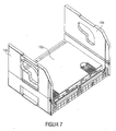
- Fig. 1 shows an inventive embodiment of a box 10 for drinks.
- the bottom 12 is not continuous in the illustrated embodiment, but consists of a grid-like structure.
- the bottom 12 is formed by a plurality of webs or struts. These are arranged close enough so that the goods to be transported, so for example a bottle, can not fall through the bottom of the box or tilts uncontrollably when the edge of a bottle tilts into one of the cavities between the webs.
- the box further comprises two pairs of respective opposite side walls 14a, 14b and 16a, 16b extending from the bottom 12 upwards, ie. extend in the vertical direction 18.
- the removal height 20 is less than the height of the remaining side walls 14a, 14b and 16a, so that a lateral opening is formed which allows access to or removal of contained and transported in the box bottles or products through the side opening.
- Above the first side wall 16b is no further Structure of the box.
- On the floor 12 of the in Fig. 1 a plurality of sleeves are arranged, of which the sleeve 22a and the sleeve 22b are highlighted by way of example.
- the lateral opening for removal of the products is thus produced in that the first side wall 16b has a lower height than the adjacent or the remaining side walls. Height should be understood here, as in the following figures, the dimension in the positive vertical direction 18.
- the term "top” denotes a position in the positive vertical direction 18, the term “bottom” a position having a smaller coordinate in the vertical direction 18.
- a lateral opening is defined or formed, which allows access to the removal of transported in the box bottles.
- other products may be transported in the box.
- So-called “six-packs” can also be transported, ie pre-packed containers of six bottles.
- the side wall is not in its entire length, the low removal height 20, but extending from the adjacent side walls 14a and 14b fixed side wall sections in the lateral opening, the lateral opening still remains so large that a Removal of the products or bottles is guaranteed.
- Such boxes can have increased stability.
- a box 10 further comprises a movable side wall portion 23 which is rotatably supported relative to a fixed first side wall 16b via hinges 24a to 24c.
- the movable side wall portion 23 is in Fig. 1 shown in a folded-down position, where this is folded down with respect to the first side wall 16b.
- the movable sidewall region 23 extends upwardly in the vertical direction 18.
- the security can be additionally increased to the extent that located in the box 10 bottles do not tilt outward.
- the movable part can be used to present product information or the like.
- the side walls 14a and 14b adjacent to the first side wall 16b each have a handle opening 28a and 28b on which the box can be lifted and carried.
- the handle openings both a first, view parallel to the ground extending Opening region and a second, extending substantially in the vertical direction opening area, whose function is described below with reference to Fig. 3 will be explained in more detail.
- the side walls 14a and 14b adjacent to the first side wall 16b have beveled edge portions 30a and 30b at their end facing the first side wall, through which light may fall into the cases even when they are stacked.
- the ends of the side walls 14a and 14b adjoining the first side wall 16b have a smaller height than at their opposite end.
- the recessed part of the side wall is substantially triangular, any other shapes of the recess can also be used for alternative embodiments.
- the height increases from the first side wall 16b side walls 14a and 14b continuously up to the maximum height.
- the increase in height may also be staircase or stepwise.
- the contours of the upper ends of the side walls 14a, 14b and 16a are designed such that when stacking with the contour or the structure of the bottom of another box engages (see, for example Fig. 3 ), so that the boxes can be stacked on top of each other. Nevertheless, the side opening defined by the first side wall 16b allows bottles or bottle packs, such as six-packs, to be taken out of the interior of the box, even when stacked.
- the inwardly facing surfaces of the sidewalls 14a, 14b and 16a are of light color so that the light incidence caused by the apertures 30a and 30b makes the bottles within the box readily visible to the outside observer ,
- the surfaces are covered with product references or advertisements.
- the embodiment of the invention shown further comprises at least one of the side walls (in the case of the side wall 14b shown here) a plurality of vertically extending, from a side surface inwardly protruding ridges 32a to 32d, which prevent the bottles inside the box are held by the sleeves, with their entire side surface come into contact with the side wall and dirty it over a large area.
- the webs 32a to 32d are each arranged so that the bottles abut with their outermost radius at the positions of the webs 32a to 32d on the outer wall. This can be prevented be that large areas of the inner surfaces of the side walls are dirty, since this is the case only for the webs.
- Fig.2 shows the embodiment of the box 10 of Fig. 1 in with 3 sixpacks filling condition.
- the six-packs 40a, 40b and 40c each contain six individual bottles not shown here for reasons of clarity.
- the six-packs are in addition to the sleeves, which engage from below in the open for this purpose bottom six-pack, held by the webs 40a and 40b, which, as in Fig. 1 represented, are arranged on the bottom 12 of the box 10.
- Fig. 3 which shows two boxes 10 and 10a in the stacked state
- the products or bottles can also be removed from the lower box 10 in the stacked state.
- the six-packs 40a, 40b and 40c if they are transported or presented as an alternative to individual bottles in the boxes.
- the in Fig. 1 illustrated special embodiment of a box with respect to the bottles to be transported on a high flexibility, since on the one hand six packs and on the other individual bottles can be transported with the box.
- the sleeve arrangement can be chosen differently.
- both embodiments are possible, since each individual bottle, which is inserted in one of the free spaces between sleeves and / or webs, in each of four directions either through a side wall of a web, through a quill or one of the side walls 14a, 14b, 16a or 16b of the box is supported so that it is stably supported for transport.
- the side wall 16b prevents this in conjunction with the sleeves, that during transport, the bottles can tip out of the box 10, so the side wall 16b is dimensioned so that during transport it is tilted out of the Box prevents. It still remains low enough that the bottles can be removed from the front of the box, even if there is another box 10a on the box 10.
- the bottles are first lifted slightly and then tilted out to the front. This is made possible in some embodiments by a special embodiment of the sleeves, as described below with reference to Fig. 12 will be described in more detail.
- Fig. 3 clearly shows another property of some embodiments of the present invention, namely the particular configuration of the handle openings 28a and 28b.
- the handle opening is curved and extends both horizontally and vertically.
- the handle opening 28a has a first opening area 50a extending parallel to the floor 12 and a second opening area 50b extending substantially in the vertical direction 18.
- the demarcation between vertical and horizontal opening area is in Fig. 3 merely as an example.
- the handle opening 28a thus also extends with a significant extension in the vertical direction, so that the handle opening 28a can also be used in the vertical opening area by a person.
- handle opening 28a may be shaped differently than in FIG Fig. 3 pointed embodiment. For example, this may also have a square or rectangular cross-section, so that the box can be lifted both from above by means of the horizontal opening portion 50a and from the side by means of the vertical opening portion 50b.
- the vertical opening region is located on the side associated with the first side wall 16b and merges with the outer contour (that is, at the contour pointing in the direction of the first side wall) with a large radius into the horizontal opening region 50a.
- the box when the box is lifted, it can also be gripped in the radius, so that when the vertical opening area is on the side associated with the first side wall 16b, the box tilts backwards (in the direction of the side wall 16a) that falling out of the individual bottles is additionally prevented by the inclination of the box when carrying.
- FIG. 11 shows a view from below of a further embodiment of the invention, illustrates, by a special design of the bottom 12 in the area adjacent to the first side wall 16b area 50 additionally increases the security.
- the floor 12 is not formed over the entire surface, but formed to save weight and for easier cleaning by an arrangement of ribs. These cover the surface of the bottom 12 so that the individual bottles rest securely on the floor 12 with their bottom of the bottle.
- the number or surface density of the ribs is increased compared with the remaining region, so that the bottles located there do not tilt outwards by themselves can, if they are tilted by external influences from its rest position slightly toward the first side wall 16b. This is avoided by placing the ribs in the region 50 adjacent the first sidewall 16b so close that the edge of a bottle can not tilt between the void spaces between two adjacent ribs.
- the floor 12 has a support surface for the bottles that is larger than the support surface provided on average over the floor per unit area, to allow secure retention of the bottles.
- the bottom 12 at the adjacent to the side walls 14a, 14b and 16a region an increase of a plurality of ribs whose contour is formed so that when placed on another box in the interior of the side walls in the contour of the side walls of the other Box intervenes to ensure stackability and a secure footing when stacked.
- a strut 52 which extends from the side wall 16a to the first side wall 16b and the webs in the vertical direction have a greater extent than the other webs of the soil.
- This strut 52 serves to additionally support the first side wall 16b of lesser height in order to increase the stability of the box.
- the strut 52 is centrally located so that the strut, which extends farther down than the rest of the ground, does not interfere with the removal of the bottles from the lower box when stacked.
- Fig. 5 shows a further embodiment of the present invention, which differs from the embodiments discussed with reference to the preceding figures essentially in that with the in Fig. 5 shown embodiment, other bottle sizes can be transported. While that in Fig. 1 embodiment shown adapted to bottles with the content 0.5 1, which is in Fig. 5 shown embodiment of a box adapted to bottles with content of 0.33 1. Therefore, the embodiment differs from Fig. 5 essentially in the arrangement of the sleeves of the embodiment of Fig. 1 as well as in the thickness of the side walls 14a, 14b and 16a, which has been changed to hold the bottles inside the box with the same outer volume of the box. For example, the in Fig.
- the box shown has five sleeves 54a, 54b, 54c, 54d and 54e adjacent to the first side wall 16b to hold a total of six bottles of 0.33 liters of contents in the first row. Furthermore, the box of Fig. 5 only a continuous web 56 in the middle of the box, so that alternatively four six-packs can be transported with the box.
- FIG Fig. 5 unlike the embodiments of FIGS. 1 to 4 the box with upwardly folded movable side wall portion 23 on the first side wall 16b.
- the design features of the box of Fig. 5 those of Fig. 1 correspond and each have identical functionality is based on a re-discussion of the box with Fig. 1 omitted matching components.
- the in Fig. 5 shown box as well as the in Fig. 1 shown box on the side wall 16 a, which is opposite to the first side wall 16 b, at least one opening 58 which extends through the side wall 16 a, so that the box by means of the opening on a wall or a shelf or the like can be hung or hung.
- Fig. 6 This in Fig. 6 embodiment shown is also configured for the transport of 24 pieces of bottles each with 0.33 1 content and corresponds in many parts to the in Fig. 5 shown embodiment.
- Fig. 8 shows all the side walls 14a, 14b and 16a in the folded state, so that in the folded state, the box can be easily transported back to the brewery or a bottler, without consuming a lot of storage space. This can significantly reduce transport costs.
- FIGS. 6 to 8 the hinged side walls 14a, 14b and 16a are shown only for a box configured to carry 24 bottles of 0.33 liters each, it goes without saying that the in Fig. 1 shown box for 0.5 1 bottles with hinged side walls can be equipped.
- Fig. 1 shown box for 0.5 1 bottles with hinged side walls can be equipped.
- Fig. 9 illustrates the embodiment of Fig. 5 when loaded, there are 24 bottles in the box.
- the movable side wall portion 23 is in the unfolded position so as to additionally secure the bottles of the foremost row or to affix product labels for transport on the outside of the flexible member 23 which are not relevant to the presentation of the product.
- Fig. 10 shows the embodiment of Fig. 5 with an alternative form of loading, namely with four six-packs 70a, 70b, 70c and 70d.
- Fig. 11 Finally, a plan view of the embodiment of Fig. 5 4, it can be seen that the quill 54c has a different geometric shape than the quills 54a, 54b and 54d or 54e, to allow the setting of six-packs.
- the central sleeve 54c may, of course, have the same shape as the remaining sleeves, such as sleeve 54a.
- any other quills may have the shape of the sleeve 54c.
- Fig. 12 shows an enlarged view of the sleeves 54a to 54c, so that their special shape is visible, which allows in conjunction with the first side wall 16b to keep the bottles both safe and forward removable.
- some embodiments of sleeves have an outer surface whose height in the vertical direction 18 is not constant.
- the outer boundary surface of the sleeve 54a is to be understood below as the created surface 70, that is to say the surface or those surface elements which delimit the sleeve laterally, ie in all directions orthogonal to the vertical direction 18.
- the outer boundary surface 70 has a varying height, as already described above.
- the quill is in a first side surface area 75, which is parallel to the first side wall 16b extends and a bottle backwards (in the direction 72 away from the first side wall 16b) secures less than in a second side surface area 76 securing the bottle against tilting in a direction 74 parallel to the first side wall 16b ,
- quill 54a which has a substantially diamond-shaped cross-section, which has a tip in the direction of the first side wall 16b, the function of preventing the tilting backwards so a first boundary surface area 75 is met, the quill substantially in the direction parallel to first side wall 16b completes.
- the first side surface area 75 is lower than the second side surface area 76 in order to allow for tilting the bottles forward tilting without having to raise the bottle so far that it may already abut the bottom of another box that is stacked on the considered box is.
- the second boundary area 76 prevents tilting in the direction parallel to the first side wall 16b and can therefore be higher to increase the stability.
- both the sleeves 54a and 54b and the sleeve 54c provide maximum stability while allowing for tipping out forward, in that the sleeves have a lower height in the direction parallel to the side wall than in the direction perpendicular to the side wall.
- the quills are in Fig. 12 provided with outer boundary surfaces which are concavely inwardly arched between the tips of the substantially diamond-shaped basic shape, wherein the radius of the curvature substantially corresponds to the diameter of a bottle in order to hold the bottle still safe can.
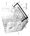
- FIG. 13 shows a box that is essentially the box Fig. 1 so that a re-description of the various already based on the FIG. 1 described elements no longer occurs.
- the box comprises according to Fig. 13 (a) a locking member 100 having a bracket 102 that includes two opposite ends.
- a first strut 104 is arranged, and at a second end 102 b of the bracket 102, a second strut 106 is arranged.
- the bracket 102 facing away from the ends 104a and 106a of the struts 104, 106 are rotatably disposed on the opposite side surfaces or end surfaces 14a and 14b.
- the blocking element or transport protection element 100 is in a position which is between a first position and a second position. Based on Fig. 13 (b) is the in Fig.
- the bracket 102 is halfway up the side walls 14a and 14b, but the present invention is not limited to this arrangement. Rather, the bracket 102 may be arranged either higher or lower depending on the circumstances.
- the struts 104 and 106 are configured and stored such that when folding the bracket 102 from the in Fig. 13 (a) shown position in the Fig. 13 (b) shown position of the bracket 102 occupies a desired distance to the lower, lower side wall 116b. How out Fig.
- the side walls 14a and 14b and the low side wall 16b facing surfaces of these two end walls are structured to the struts 104 and 106 and the region in which the bracket 102 is connected to the struts 104 and 106, ie opposite ends 102a and 102b of the bracket 102 in recesses or recesses, in such a way that adjusts a flush front surface.
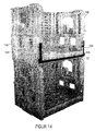
- Fig. 14 shows a stacked arrangement of a box Fig. 1 , according to a box according to Fig. 13 is arranged, but here the situation is shown in which the bracket 102 is arranged in a second position in which it is arranged overlapping with the low side wall 14 b.
- the low side wall 16b is also structured by recesses or recesses so as to secure the bracket 102 in the in Fig. 14 shown, so that a flush front surface of the side wall 16b adjusts.
- FIGS. 13 (b) and 14 how out FIGS. 13 (b) and 14 Further, the opposite ends 102a and 102b of the yoke 102 are configured to be in the first position shown in FIG Fig. 13 (b) is shown, the respective side wall 14a and 14b engage around so as to ensure a locking and secure positioning of the bracket 102. Similarly, at the in Fig. 14 shown position secure positioning of the bracket 102 achieved in that corresponding engagement elements formed in the low wall, engage with the bracket 102 engage.
- the advantage of this embodiment is that now an additional transport protection element is provided, which during transport in the in Fig. 13 (b) is shown, and thus can act on in-box products to prevent movement thereof in the direction of the opening, in other words, to provide a further barrier against falling out of the products.
- the bracket is rotatably connected to the side surfaces or end surfaces of the box, and can be easily removed from the in Fig. 13 (b) shown, locked position in the open position, so that a free access to the products contained in the box is possible.
- the invention is not based on the Figures 13 and 14 Rather, instead of the arrangement of the bracket 102 at about half height of the end walls, a different positioning may be chosen, for example, the distance from the low wall 16b to one third of the height of the side walls or two thirds of the height of the side walls become. Further, according to one embodiment, it may be provided to telescope the struts 104 and 106 so as to position the stirrup 102 from the situation in FIG Fig. 14 to be arranged at different heights along the height of the side walls, so that the height of the locking element 102 can be flexibly adjusted depending on the products contained in the box.
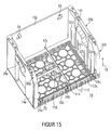
- Fig. 15 a box shows, already based on the Fig. 1 has been described, but differs in terms of the design of the bottom 12.
- a box 112 is provided, which is arranged on the bottom of the box detachably from the same.
- the in Fig. 16 Insert 112 shown includes an upper surface 112a, on which a first strut 114 is shown, which extends parallel to the opposite end walls 14a and 14b over the entire depth of the box to the rear wall 16a.
- Another strut, the crossbar 116 is provided which extends from the side wall 14a at about half the height of the depth of the box to the first strut 114.
- the insert 112 may be provided to receive carton-packaged products having dimensions corresponding to the resulting compartments in the insert 112.
- any products may be provided to comply with in the box Fig. 16 to be included, according to the invention for various products and various inserts 112 may be arranged detachably in the box.
- FIG. 16 Some examples of the configuration of the inserts 112 are shown, for example, wherein the surface 112a in FIG Fig. 16 (a) with rectangular and circular recesses may be provided to simultaneously accommodate products having a corresponding footprint.
- Fig. 16 (b) shows, similar to in Fig. 15 , the arrangement of struts on the upper surface 1 12a of the insert 112, and according to Fig. 16 (c) For example, quills may be provided on the top surface 112a, similar to that shown in FIG FIGS. 1 to 12 has been described.
- the Fig. 16 shows, similar to in Fig. 15 , the arrangement of struts on the upper surface 1 12a of the insert 112, and according to Fig. 16 (c)
- quills may be provided on the top surface 112a, similar to that shown in FIG FIGS. 1 to 12 has been described.
- the Fig. 16 shows, similar to in Fig. 15 , the arrangement of struts on the upper surface 1 12a of the insert 11
- Figure 11 shows a lower surface 112b of the insert 112, with corner-mounted elements 118a-118d serving to engage corresponding elements or recesses in the bottom 12 of the box, the elements 118 preferably being configured such that, for example after a latching with the case bottom a solution of the case bottom is possible only using special tools, so that a box manufacturer can customize the boxes in different ways according to the wishes of the customer, without the customer who uses the box, a possibility has to replace the insert for use with other products.
- the boxes can be tailored according to the requirements of the customers and in particular can respond flexibly to increased demands for boxes with certain applications, when at the same time boxes for other products are not so much in demand.
- the blocking element comprises the in Fig. 13 and 14 shown boxes a locking element with a movable member to ensure a secure locking of the locking element in its closed position.
- Fig. 17 shows a section of a box according to a first embodiment, wherein Fig. 17 (a) a front view of the left side of the box Fig. 13 (b) shows. It should be noted that the right side of the box for the sake of simplicity is not shown, but can be configured according to the left side. Fig. 17 (b) shows a sectional view to illustrate the locking mechanism.
- the blocking element 102 comprises a bracket 102, which differs from the in Fig. 13 4, in that the bracket comprises two struts 102c and 102d extending between the opposite side walls 14a and 14b (see FIG Fig. 13 ).
- the ends of the struts 102c and 102d are integrally connected to the vertical struts 104 and 106, respectively, so that a blocking element corresponding to the in FIG Fig. 13 shown blocking element is obtained.
- embodiments of the invention are not limited to this embodiment of the blocking element 100, but rather also a blocking element in the form of in Fig.
- the box further comprises a locking mechanism 200, which in the in Fig. 17 (a) shown embodiment on the bracket 102, more precisely on the bracket strut 102c adjacent to the side wall 14a is arranged.
- the locking mechanism 200 includes an actuator 202 and a housing 204 in which the remaining elements of the mechanism are received.
- the actuator 202 is movable horizontally to actuate a latch disposed within the housing in the manner described below.
- Fig. 17 (b) shows details of the locking mechanism Fig. 17 (a)
- the locking mechanism comprises a latch member 206 which is horizontally movable as indicated by the arrow in FIG Fig. 17 (b) is shown.
- the locking element 206 is movably mounted within the housing 204, and via a spring 208 in the position which in Fig. 17 (b) shown is biased.
- the actuator 202 is operatively connected to the latch member 206 for movement of the latch member 206 out of the position shown in FIG Fig. 17 (b) shown position in a retracted to the right position.
- the side wall 14a comprises a recess 210 in which the locking element 206 in its first, in Fig. 17 (b) shown position is arranged.
- a locking of the locking element 100 takes place at the in Fig. 17 (a) or in Fig. 13 (b) shown position. Due to the locking element 206, which is located within the recess 210, a movement of the locking element 100 in the in Fig. 13 (a) shown position prevented. In order to allow such a rotational movement, it is necessary, the latch 206 from the in Fig. 17 (b) After a corresponding distance has been covered by actuation of the element 202 by the bolt, this is outside the recess 210 and a folding over of the locking element, for example in the in Fig. 13 shown position is allowed or allowed.
- the advantage of the embodiment according to the invention is that now a secure positioning of the locking element is achieved at its first position, which in particular during transport unintentional opening of the element and thus falling out of products contained within the container is prevented.
- the use of a locking mechanism with a movable element is advantageous over a pure snap closure, as a result, a secure locking is achieved.
- the locking element When locked, the locking element may become jammed due to knocks or bumps, to which the box is exposed or open by movement of the goods inside the box.
- the locking mechanism comprises instead of Fig. 17 known horizontal locking element a vertical locking element.
- the locking mechanism 200 is disposed in the locking member and includes a vertically movable actuating member 202.
- Fig. 18 (b) shows a side sectional view of a section of the side wall, wherein the viewing direction is directed from the side to the side wall.
- the locking element or latch member 206 is movably disposed within a recess 212 of the locking element.
- the locking element 206 is vertically movable, as shown by the arrow and is by a spring 208 in the in Fig. 18 (a) biased position shown.
- the side wall 14a includes the recess 210 with the locking element 206 in its in Fig. 18 (b) shown position engages, so that movement of the locking element is prevented in the direction of the curved arrow.
- the latch member 210 is operatively connected to the actuator 202 so that movement thereof downwardly causes the latch member to move downward against the spring force of the spring 208 and eventually exit the recess 210 so as to move the latch member in the direction the curved arrow in Fig. 18 (b) allows.
- Fig. 19 shows a further embodiment of the invention, which is similar to that in Fig. 18 shown embodiment, but different than in Fig. 18 the active elements of the locking mechanism are disposed in the side wall 14a.
- the locking mechanism 200 includes the actuator 202, which is disposed in an upper portion of the side wall 14a.
- Fig. 19 (b) shows a sectional view similar to that Fig. 18 (b) , As can be seen, the locking element 206 is now arranged in the recess 210 in the side wall 14a and in the in Fig. 19 (b) biased down direction by means of the spring 208.
- the actuating element 202 which is operatively connected to the locking element 206, the same can be moved vertically, as indicated by the double arrow in FIG Fig. 19 (b) is shown.
- the latch member 206 is shown in the biased position in which it engages the recess 212 in the locking member, so that movement of the locking member in the direction of the curved arrow is avoided.
- one of the low side wall 16b facing, narrow surface 220 including a first surface portion 220a spaced from the low sidewall 16b and a second surface portion 220b between the low sidewall 16b and the first surface portion 220a that is recessed toward the backwall 16b with respect to the first surface portion 220a; such that the surface 220 of the side wall 14a facing the low wall 16b has a projection 222.
- the side wall 14a is configured in accordance with embodiments such that the surface portions 220a and 220b are offset from one another such that the blocking element abuts in its first position on the second surface portion 220b, wherein the projection 222 is dimensioned such that the first surface portion 220a of the wall 14a and a surface of the barrier member facing the low wall 16b, when in the first position, is flush so as to provide a substantially flush front surface of the side walls of the box.
- the locking mechanism according to the invention is not based on the 17 to 19 rather, they can be implemented in other ways as well.
- a common operating member may be provided along the length of one of the bar struts, additionally incorporating a suitable gear mechanism which effects movement of the operating member into opposite movements of the two latch members operatively connected thereto, such that upon actuation of the latch member in one direction an unlocking of cooperating with the two opposite side surfaces 14a and 14b locking elements 206 is effected.
- the horizontal latching mechanism may be incorporated in one of the bar struts, with a corresponding release mechanism being either part of the bar strut or part of the sidewall.
- the Fig. 20 shows a further embodiment of a locking mechanism according to the present invention.
- the blocking element 100 comprises a recess 230 in the area in which the bar struts 102c and 102d are connected to the vertical strut 104.
- the recess is located between the upper bar strut 102c and the lower bar strut 102d.
- the recess may also be provided at other positions.
- the side wall 14a comprises a hook-shaped projection 232, which projects in the direction of the low side wall 16b, that is to say in front, over the second surface section 220b of the side wall 14a.
- the blocking element 100 is in Fig.
- the blocking element 100 in the basis of the Fig. 20 described embodiments not only rotatably mounted, but also vertically movable.
- the hook portion of the projection 232 engages an outer surface of the strut 104 through the recess 230, so that movement of the locking member 100 is prevented in its open position to the front.
- the locking member 100 is disposed in its first position such that there is a clearance 234 between the bracket 102 and the projection 222 of the side wall 14a.
- a movable element 236 is further provided which is rotatably mounted on the upper bracket strut 102c about an axis 238 so as to interpose the in Fig. 20 shown position and another position to be moved.
- the movable member 236 includes a portion 240 disposed in the space 234 and removed from the clearance 234 by a rotational movement of the movable member about the axis 238. As long as the portion 240 is within the space 234, a vertical movement of the member 100 is prevented, and thus its release or the release of the element 100 of the hook-shaped projection 232.
- the movable element 234 is rotated to remove the portion 240 from the gap 234, thereby allowing a vertical movement of the locking element upwards, whereby the hook-shaped projection 232, the blocking element 100 releases, so that it can be folded.
- Fig. 21 shows a side sectional view illustrating the configuration of the protrusion 232.
- the projection comprises a hook-shaped portion 232, wherein the locking member 104 is configured in the corresponding location for engagement with this projection 232a.
- the protrusion 232 may extend outwardly beyond the thickness of the locking member 104 so that the portion 232a engages an outer surface of the locking member. Movement of the locking member into the clearance 234 causes the engagement of the projection 232a with the outer surface 104a of the locking member 104 to be released, causing movement of the locking member in the direction of the locking member Fig. 21 shown, curved arrow is possible. If such a movement is undesirable, takes place by means of the basis of Fig. 20 element shown a locking of the locking element to the in Fig. 21 shown Position, and due to the arrangement of the portion 240 of the movable member 236 in the space 234, a vertical movement of the element is no longer possible upwards.
- beverage cans and any other cylindrical objects such as hair sprays, deodoses or the like can be transported with the boxes according to the invention.
- the boxes with a lateral opening are also suitable for completely different types of products, which may also differ from a cylindrical basic shape.
- the boxes are universally applicable for all sorts of products, as they allow that in the stacked state, the products can also be removed laterally from the box. This great advantage is not limited to the type of goods transported.
Description
Die vorliegende Erfindung befasst sich mit Kisten zum Transport von Waren, die es ermöglichen, die in der Kiste transportierten Waren einem Verbraucher zu präsentieren und diesem den Zugriff auf die Waren in der Kiste zu erleichtern.The present invention relates to boxes for the transport of goods, which make it possible to present the goods transported in the box to a consumer and to facilitate his access to the goods in the box.
Eine Vielzahl von Produkten wird in nach oben geöffneten Kisten transportiert. Beispielsweise sind eine Vielzahl von unterschiedlichen Kistenformen in der Getränkeindustrie bekannt, um Getränkeflaschen oder kleinere Gebinde von Getränkeflaschen (beispielsweise sogenannte "Sixpacks" von der Produktion zum Einzelhandel zu transportieren. Im Einzelhandel werden die Kisten üblicherweise gestapelt, so dass ein Zugriff nur von oben erfolgen kann und daher auf Produkte, die sich in einer Kiste, die sich in einer unteren Position im Stapel befindet, nur zugegriffen werden kann, wenn sämtliche darüber liegenden Kisten entfernt werden. Dies ist äußerst unkomfortabel, kraft- und zeitaufwändig. Ferner sind solche Kisten im Regelfall nur für den Transport von Gütern einer bestimmten Art, z.B. Flaschen, bestimmt, so dass für den Transport anderer Güter andere Kisten eingesetzt werden müssen.A large number of products are transported in boxes opened at the top. For example, a variety of different box shapes are known in the beverage industry for transporting beverage bottles or smaller containers of beverage bottles (for example, so-called "six-packs") from production to retail, whereas in retail the boxes are usually stacked so that access can only be from above and therefore, products that can only be accessed in a box that is in a lower position in the stack when all the boxes above are removed, which is extremely uncomfortable, time consuming and laborious only for the transport of goods of a certain kind, eg bottles, so that other boxes have to be used for the transport of other goods.
Die
Die
Die
Die
Der vorliegenden Erfindung die Aufgabe zugrunde, eine verbesserte Kiste zu schaffen, die zum einen einen einfachen und effizienten Zugriff auf Produkte innerhalb der Kiste ermöglicht und zum anderen gleichzeitig einen sicheren Transport der in der Kiste befindlichen Produkte sicherstellt, insbesondere diese gegen ein Herausfallen aus der Kiste sichert.The present invention has for its object to provide an improved box, which allows for a simple and efficient access to products within the box and at the same time ensures a safe transport of products located in the box, especially against falling out of the box guaranteed.
Diese Aufgabe wird durch eine Kiste nach Anspruch 1 gelöst.This object is achieved by a box according to claim 1.
Ausführungsbeispiele der vorliegenden Erfindung schaffen eine Kiste mit einem Boden und zumindest zwei Paaren von sich jeweils gegenüberliegenden Seitenwänden, wobei eine erste der Seitenwände so gestaltet ist, dass diese eine Entnahme von der in der Kiste enthaltenen Produkten ermöglicht. Dazu erstreckt sich die erste Seitenwand von dem Boden in der vertikalen Richtung zumindest teilweise nur um eine geringere Entnahmehöhe nach oben, welche kleiner ist, als die Höhe einer oder mehrerer der übrigen Seitenwände. Die Entnahmehöhe ist so bestimmt, dass von der ersten Seitenwand eine seitliche Öffnung mit einer Abmessung definiert wird, die einen Zugriff bzw. die Entnahme von in der Kiste enthaltenen Produkten durch die seitliche Öffnung ermöglicht. Die Kiste umfasst ferner ein Sperrelement, das sich zwischen den zwei gegenüberliegenden Seitenwänden erstreckt, die an die erste Seitenwand angrenzen, und das zwischen einer ersten Position und einer zweiten Position bewegbar ist, wobei das Sperrelement in der ersten Position zwischen den gegenüberliegenden Seitenwänden und beabstandet von der ersten Seitenwand angeordnet ist, wobei das Sperrelement in der zweiten Position mit der ersten Seitenwand überlappend angeordnet ist, , wobei die Kiste ferner einen Verriegelungsmechanismus mit einem beweglichen Element umfasst, das konfiguriert ist, um mit den gegenüberliegenden Seitenwänden und/oder dem Sperrelement Eingriff zu nehmen, um das Sperrelement in seiner ersten Position mit den gegenüberliegenden Seitenwänden zu verriegeln. Das Sperrelement umfasst einen Bügel, eine erste Strebe, die an einem ersten Ende des Bügels angeordnet ist, und eine zweite Strebe, die an einem zweiten Ende des Bügels angeordnet ist, wobei die dem Bügel abgewandeten Enden der Streben drehbeweglich an den gegenüberliegenden Seitenwänden angeordnet sindEmbodiments of the present invention provide a box having a bottom and at least two pairs of opposing side walls, wherein a first of the side panels is configured to permit removal from the products contained in the box. For this purpose, the first side wall extends at least partially from the bottom in the vertical direction only by a smaller removal height, which is smaller than the height of one or more of the remaining side walls. The extraction height is determined so that from the first side wall a lateral opening is defined with a dimension that allows access or removal of products contained in the box through the side opening. The box further includes a barrier member extending between the two opposed side walls adjacent the first side wall and movable between a first position and a second position, the locking member being in the first position between the opposed side walls and spaced from the first side wall is disposed, wherein the blocking element is arranged in the second position with the first side wall overlapping, wherein the box further comprises a locking mechanism with a movable member which is configured to engage with the opposite side walls and / or the blocking element take to lock the locking element in its first position with the opposite side walls. The locking member comprises a bracket, a first strut disposed at a first end of the bracket, and a second strut disposed at a second end of the bracket, wherein the ends of the struts facing away from the bracket are rotatably disposed on the opposite side walls
Gemäß Ausführungsbeispielen der Erfindung ist das bewegliche Element an dem Sperrelement angeordnet und umfasst einen Riegel, der in eine erste Position vorgespannt ist, wobei das bewegliche Element konfiguriert ist, um den Riegel auf eine Betätigung hin aus der ersten Position in eine zweite Position zu bewegen, wobei die gegenüberliegenden Seitenwände jeweils eine Ausnehmung aufweisen, in der der Riegel in seiner ersten Position eingreift, so dass das Sperrelement mit den gegenüberliegenden Seitenwänden verriegelt ist, und wobei der Riegel in der zweiten Position nicht in die Ausnehmungen eingreift, so dass das Sperrelement mit den gegenüberliegenden Seitenwänden nicht verriegelt ist.According to embodiments of the invention, the movable member is disposed on the locking member and includes a latch biased to a first position, the movable member configured to move the latch upon actuation from the first position to a second position. wherein the opposed side walls each have a recess in which the latch engages in its first position so that the locking element is locked to the opposite side walls, and wherein the latch in the second position does not engage in the recesses, so that the locking element with the opposite side walls is not locked.
Gemäß Ausführungsbeispielen der Erfindung umfasst der Riegel ein erstes und ein zweites Riegelelement, welche vertikal beweglich sind, wobei das erste Riegelelement in der ersten Strebe und das zweite Riegelelement in der zweiten Strebe angeordnet ist. Alternativ kann der Riegel ein erstes und ein zweites Riegelelement umfassen, die horizontal beweglich sind und in dem Bügel angeordnet sind. Gemäß diesen Ausführungsbeispielen kann das bewegliche Element ein erstes und ein zweites Betätigungselement umfassen, welche mit dem ersten bzw. zweiten Riegelelement für eine Bewegung aus der vorgespannten, ersten Position in die zweite Position zusammenwirken. Gemäß einem weiteren Ausführungsbeispiel, bei dem die Riegelelemente horizontal beweglich und in dem Bügel sind, kann das bewegliche Element ein gemeinsames Betätigungselement umfassen, das mit dem ersten und zweiten Riegelelement für eine Bewegung aus der vorgespannten, ersten Position in die zweite Position zusammenwirkt. In einem solchen Fall kann ferner ein Mechanismus vorgesehen sein, der konfiguriert ist, um die horizontale Bewegung des gemeinsamen Betätigungselements in zwei entgegengesetzte Bewegungen des ersten und zweiten Riegelelements bzw. Verriegelungselements umzusetzen.According to embodiments of the invention, the latch comprises a first and a second latch member which are vertically movable, wherein the first latch member in the first strut and the second latch member in the second strut is arranged. Alternatively, the latch may include a first and a second latch member which are horizontally movable and disposed in the bracket. In accordance with these embodiments, the movable member may include first and second actuators which cooperate with the first and second latch members, respectively, for movement from the biased first position to the second position. According to another embodiment, wherein the latch members are horizontally movable and in the bracket, the movable member may comprise a common actuator cooperating with the first and second latch members for movement from the biased first position to the second position. In such a case, there may further be provided a mechanism configured to translate the horizontal movement of the common operating member into two opposite movements of the first and second locking element.
Gemäß einem weiteren Ausführungsbeispiel ist das Sperrelement drehbeweglich und vertikal verschiebbar an den gegenüberliegenden Seitenwänden angeordnet, wobei das Sperrelement ein erstes Riegelelement und ein zweites Riegelelement aufweist, und wobei die gegenüberliegenden Seitenwände ein drittes bzw. ein viertes Riegelelement umfassen. Die Riegelelemente sind ausgestaltet, so dass das erste und das dritte Riegelelement und das zweite und das vierte Riegelelement miteinander Eingriff nehmen, wenn das Sperrelement an einer ersten vertikalen Position angeordnet ist, und so dass das erste und das dritte Riegelelement und das zweite und das vierte Riegelelement außer Eingriff sind, wenn das Sperrelement an seiner zweiten vertikalen Position angeordnet ist. Das bewegliche Element ist zwischen einer ersten Position und einer zweiten Position bewegbar, wobei das Sperrelement an der ersten vertikalen Position gehalten wird, wenn das bewegliche Element an seiner ersten Position ist, und wobei eine Bewegung des Sperrelements von der ersten vertikalen Position in die zweite vertikale Position zugelassen wird, wenn das bewegliche Element an seiner zweiten Position ist.According to a further embodiment, the blocking element is rotatably and vertically displaceably arranged on the opposite side walls, wherein the blocking element a first locking element and a second locking element, and wherein the opposite side walls comprise a third and a fourth locking element. The latch members are configured so that the first and third latch members and the second and fourth latch members engage with each other when the latch member is disposed at a first vertical position, and so that the first and third latch members and the second and fourth latch members Bar element are disengaged when the blocking element is arranged at its second vertical position. The movable member is movable between a first position and a second position, the locking member being held at the first vertical position when the movable member is at its first position, and wherein movement of the locking member from the first vertical position to the second vertical position Position is permitted when the movable element is in its second position.
Gemäß diesem Ausführungsbeispiel kann das Sperrelement einen Bügel, eine erste Strebe, die an einem ersten Ende des Bügels angeordnet ist, und eine zweite Strebe, die an einem zweiten Ende des Bügels angeordnet ist, umfassen, wobei die dem Bügel abgewandten Enden der Streben drehbeweglich und vertikal verschiebbar an den gegenüberliegenden Seitenwänden angeordnet sind. Jede der gegenüberliegenden Seitenwände umfasst eine der niedrigen Seitenwand abgewandte Oberfläche, die einen ersten, von der niedrigen Seitenwand beabstandeten Oberflächenabschnitt und einen zweiten Oberflächenabschnitt aufweist, der bezüglich des ersten Oberflächenabschnitts zurückgesetzt ist. In seiner ersten Position ist das Sperrelement an dem zweiten Oberflächenabschnitt angeordnet, wobei zwischen dem Bügel und dem ersten Oberflächenabschnitt ein Zwischenraum ist, wenn das Sperrelement in der ersten vertikalen Position angeordnet ist, wobei das bewegliche Element in seiner ersten Position in dem Zwischenraum angeordnet ist, und so eine vertikale Bewegung des Sperrelements verhindert.According to this embodiment, the locking element may comprise a bracket, a first strut, which is arranged at a first end of the bracket, and a second strut, which is arranged at a second end of the bracket, wherein the ends of the struts facing away from the bracket rotatably and are arranged vertically displaceable on the opposite side walls. Each of the opposing sidewalls includes a low sidewall facing surface having a first surface portion spaced from the low sidewall and a second surface portion recessed with respect to the first surface portion. In its first position, the locking member is disposed on the second surface portion, with a gap between the bracket and the first surface portion when the locking member is disposed in the first vertical position, the movable member being disposed in its first position in the gap, and thus prevents vertical movement of the locking element.
Das Sperrelement umfasst gemäß Ausführungsbeispielen einen Bügel, der sich zwischen den gegenüberliegenden Seitenwänden erstreckt, und zwei an den entgegengesetzten Enden des Bügels angeordnete Streben, wobei ein erstes Ende der Streben an den entgegengesetzten Enden des Bügels angeordnet ist, und wobei ein zweites Ende der Streben drehbeweglich an der entsprechenden Seitenwand angeordnet ist. Die entgegengesetzten Seitenwände und die erste Seitenwand können Ausnehmungen umfassen, um den Bügel und die Streben aufzunehmen, wobei die Ausnehmungen derart sein können, dass die Streben und der Bügel in der ersten bzw. zweiten Position des Sperrelements mit einer der ersten Seitenwand zugewandten Oberfläche der gegenüberliegenden Seitenwände bzw. mit einer äußeren Oberfläche der einen Seitenwand bündig sind. Das Sperrelement kann an der zweiten Position mit einem Abstand von dem Boden angeordnet sein, der etwa einem Drittel, einer Hälfte oder zwei Drittel der Höhe der entgegengesetzten Seitenwände entspricht. Ferner kann das Sperrelement ausgebildet sein, um zusätzlich an einer weiteren Position beabstandet von der ersten Seitenwand angeordnet zu werden, wobei in diesem Fall die Streben teleskopartig ausgebildet sein können, um das Sperrelement wahlweise an der zweiten oder an der weiteren Position anzuordnen.The locking member according to embodiments comprises a bracket extending between the opposed side walls and two struts disposed at the opposite ends of the bracket, a first end of the struts being disposed at the opposite ends of the bracket, and a second end of the struts being rotatable is arranged on the corresponding side wall. The opposed sidewalls and the first sidewall may include recesses for receiving the stirrup and the struts, wherein the recesses may be such that the struts and the stirrup in the first and second positions of the detent member, respectively, have a surface of the opposed sidewall facing the first sidewall Side walls or with an outer surface of a side wall are flush. The blocking element may be arranged at the second position at a distance from the bottom, which is about one third, one half or two thirds of the height of the opposite side walls. Furthermore, the blocking element can be designed to be additionally arranged at a further position spaced from the first side wall, in which case the struts can be telescopically designed to selectively arrange the blocking element at the second or at the further position.
Gemäß Ausführungsbeispielen der Erfindung umfasst eine Kiste der oben genannten Art, die ferner einen Einsatz zum Anordnen auf dem Boden der Kiste, wobei der Einsatz abhängig von den in der Kiste aufzunehmenden Produkten ausgestaltet ist.According to embodiments of the invention, a box of the above type further comprises an insert for placing on the bottom of the box, the insert being designed depending on the products to be accommodated in the box.
Gemäß Ausführungsbeispielen kann der Einsatz mit dem Boden und/oder den Seitenflächen lösbar verbindbar sein, vorzugsweise nur unter Verwendung von Spezialwerkzeug. Der Einsatz kann plattenförmig sein, und eine dem Boden zugewandte erste Oberfläche des Einsatzes kann an eine Struktur des Bodens angepasst sein. Die der ersten Oberfläche gegenüberliegende Oberfläche des plattenförmigen Einsatzes ist entsprechend dem aufzunehmenden Produkt strukturiert. Der Einsatz kann Pinolen, Längsstreben, Querstreben und/oder Vertiefungen umfassen. Ausführungsbeispiele schaffen ferner ein System, das eine Kiste gemäß Ausführungsbeispielen der Erfindung sowie eine Mehrzahl von Einsätzen umfasst, die für verschiedene Produkte strukturiert sind, wobei einer der Einsätze wahlweise in der Kiste angeordnet werden kann.According to embodiments, the insert may be detachably connectable to the floor and / or the side surfaces, preferably only using special tools. The insert may be plate-shaped, and a bottom-facing first surface of the insert may be conformed to a structure of the floor. The first surface opposite surface of the plate-shaped insert is structured according to the male product. The insert may include sleeves, longitudinal struts, cross struts and / or depressions. Embodiments further provide a system comprising a box according to embodiments of the invention and a plurality of inserts structured for different products, wherein one of the inserts can be optionally placed in the box.
Gemäß diesem Ausführungsbeispielen wird somit ein frei konfektionierbares System geschaffen, welches ohne Weiteres an verschiedene, in der Kiste aufzunehmende Produkte angepasst werden kann, beispielsweise durch einen Dienstleister, der die Kisten entsprechend der von einem Kunden erwünschten Konfiguration bereitstellt, und die entsprechenden Einsätze vorhält, und die Kisten ohne Einsätze entsprechend konfektioniert, wobei in diesem Fall vorgesehen ist, dass die Einsätze nur unter Verwendung eines Spezialwerkzeugs austauschbar sind, welches nur der Kistenbereitsteller in seinem Besitz hat.Thus, according to these embodiments, a freely configurable system is provided which can be readily adapted to various products to be contained in the box, for example by a service provider providing the boxes according to the configuration desired by a customer and holding the appropriate inserts, and the crates assembled without inserts accordingly, in which case it is provided that the inserts are exchangeable only using a special tool, which has only the box manufacturer in his possession.
Die Kiste wird gemäß Ausführungsbeispielen der Erfindung von dem sich vom Boden nach oben erstreckenden ersten Seitenwandbereich (der auch die gesamte Seitenwand sein kann) geringerer Entnahmehöhe in vertikaler Richtung nach oben begrenzt. Das heißt, oberhalb dieses ersten Seitenwandbereichs befindet sich keine weiter kraftschlüssige Verbindung zwischen den angrenzenden Seitenwänden. Mit anderen Worten ist die erste Seitenwand zumindest teilweise weniger hoch als die umliegenden oder als einige der umliegenden Seitenwände, so dass in die Kiste auch seitlich eingegriffen werden kann, um so bei den Kisten auch im gestapelten Zustand leicht Zugriff auf Produkte zu erhalten, die sich in unteren Kisten des Stapels befinden.According to embodiments of the invention, the box will be bounded vertically upwards by the first side wall area extending from the floor (which may also be the entire side wall) of lower removal height. That is, above this first side wall area there is no further frictional connection between the adjacent side walls. In other words, the first side wall is at least partially less high than the surrounding or as some of the surrounding side walls, so that in the box can also be intervened laterally so as to easily gain access to the products in the boxes even when stacked are located in lower boxes of the stack.
Dabei ist die Höhe der ersten Seitenwand bei einigen Ausführungsbeispielen dennoch so bemessen, dass die spezifischen in der Kiste transportierten Produkte während des Transports nicht aus der Kiste fallen können. Bei einigen Ausführungsbeispielen ist die Kiste zum Transport von Flaschen oder von Flaschen, die in kleineren Gebinden vorverpackt sind, bestimmt, weswegen die erste Seitenwand eine Höhe aufweist, die ausreicht, ein Herausfallen einzelner Flaschen aus der Kiste zu verhindern. Bei einigen Ausführungsbeispielen beträgt die Höhe zwischen 1 und 10cm. Bei einigen weiteren Ausführungsbeispielen beträgt diese Höhe zwischen 2 und 5 cm, oder allgemein mehr als 2 cm.In this case, the height of the first side wall in some embodiments is nevertheless such that the specific products transported in the box can not fall out of the box during transport. In some embodiments, the box is designed to carry bottles or bottles pre-packaged in smaller containers, for which reason the first side wall has a height sufficient to prevent individual bottles from falling out of the box. In some embodiments, the height is between 1 and 10cm. In some other embodiments, this height is between 2 and 5 cm, or more generally more than 2 cm.
Bei einigen Ausführungsbeispielen weist die erste Seitenwand an ihren an die benachbarten Seitenwände angrenzenden Rändern je zwei Seitenwandabschnitte auf, die sich bis auf die Höhe der angrenzenden Seitenwände erstrecken, um die Stabilität der Kiste zu erhöhen.In some embodiments, the first sidewall has two sidewall portions at each of its edges adjacent to the adjacent sidewalls, which extend to the level of the adjacent sidewalls to increase the stability of the crate.
Bei weiteren Ausführungsbeispielen der vorliegenden Erfindung hat die Kiste vier Seitenwände, wobei zumindest in den an die erste Seitenwand angrenzenden Seitenwänden Grifföffnungen angeordnet sind. Die Grifföffnungen weisen dabei einen parallel zum Boden verlaufenden Bereich als auch einen senkrecht zum Boden verlaufenden Bereich auf. Bei einigen Ausführungsbeispielen ist der senkrecht zum Boden verlaufende Bereich in Richtung der ersten Seitenwand angeordnet. Bei einigen Ausführungsbeispielen geht darüber hinaus der erste, horizontale und im wesentlichen parallel zum Boden verlaufende Öffnungsabschnitt in den vertikalen Öffnungsabschnitt mit einem Radius über, der groß genug ist, um die Kiste auch im Radius greifen zu können. Bei diesen Ausführungsbeispielen der Erfindung ist es folglich möglich, die Kiste auch im Radius oder im vertikalen Öffnungsabschnitt zu greifen und zu heben, so dass diese beim Greifen nach hinten kippt. Dies verringert während des Transports die Wahrscheinlichkeit des Herausfallens der Gegenstände wie beispielsweise der Flaschen aus der Kiste durch die Öffnungen der ersten Seitenwand.In further embodiments of the present invention, the box has four side walls, wherein grip openings are arranged at least in the side walls adjoining the first side wall. The grip openings have a region running parallel to the floor as well as a region running perpendicular to the floor. In some embodiments, the region extending perpendicular to the bottom is arranged in the direction of the first side wall. In some embodiments, moreover, the first, horizontal and substantially parallel to the bottom opening portion in the vertical opening portion with a radius that is large enough to grip the box in the radius can go over. In these embodiments of the invention, it is therefore possible to grasp and lift the box also in the radius or in the vertical opening portion, so that it tilts when gripping to the rear. This reduces the likelihood of articles falling out during transport such as the bottles from the box through the openings of the first side wall.
Gemäß einigen Ausführungsbeispielen der Erfindung weist die Kiste ferner in dem an die erste Seitenwand angrenzenden Bodenbereich eine größere Auflagefläche für die zu transportierenden Produkte vor, als im Mittel im übrigen Bereich des Bodens. Dies bedeutet mit anderen Worten, dass, wenn der Boden aus Gewichtsersparnisgründen nicht vollflächig ausgebildet ist, sondern beispielsweise aus einzelnen Streben besteht, die Anzahl der Streben pro Fläche, also die Strebendichte in dem an die erste Seitenwand angrenzenden Bereich erhöht ist. Dies führt dazu, dass ein in die Kiste in der Nähe der Seitenwand eingelegtes Gut, beispielsweise eine Getränkeflasche oder Dose mit großer Auflagefläche mit dem Boden in Kontakt ist. Dies verhindert, dass die Flasche oder die Getränkedose in Ausnehmungen zwischen die Bodenstreben gleiten oder kippen kann, so dass ein ungewolltes Herausfallen der Dose oder der Flasche während des Transports verhindert wird.According to some embodiments of the invention, the box also has in the adjacent to the first side wall floor area a larger support surface for the products to be transported, as an average in the remaining area of the floor. This means, in other words, that if the ground is not fully formed for weight-saving reasons, but for example consists of individual struts, the number of struts per area, so the butt is increased in the adjacent to the first side wall area. As a result, a good placed in the box near the side wall, for example a beverage bottle or can with a large contact surface, is in contact with the floor. This prevents the bottle or soda can from being in recesses can slide or tilt between the floor struts, so that accidental falling out of the can or bottle during transport is prevented.
Bei einigen Ausführungsbeispielen sind ferner die Seitenwände, die an die erste Seitenwand angrenzen, an der Stirnseite, an der sie an die erste Seitenwand angrenzen, weniger hoch als an der der Seitenwand gegenüberliegenden Stirnseite. Das heißt, in Richtung der Öffnung sind die an die Öffnung anschließenden Seitenwände niedriger, so dass zum einen der zur Entnahme zur Verfügung gestellte Raum vergrößert wird und so dass zum anderen der Lichteinfall bzw. der Einblickwinkel in das Innere der Kiste vergrößert wird, um so die in der Kiste transportierten Gegenstände, wie beispielsweise Flaschen oder dergleichen, besser sichtbar zu machen.Further, in some embodiments, the sidewalls adjacent the first sidewall are less high at the end face adjacent to the first sidewall than at the face opposite the sidewall. That is, in the direction of the opening, the side walls adjoining the opening are lower, so that on the one hand the space available for removal is increased and, on the other hand, the light incidence or the viewing angle in the interior of the box is increased to make the items transported in the box, such as bottles or the like, more visible.
Bei einigen weiteren Ausführungsbeispielen sind die übrigen Seitenwände, die nicht der ersten Seitenwand entsprechen, bezüglich des Bodens klappbar, so dass die Kiste in einen zusammengefalteten Zustand gebracht werden kann, in der die übrigen Seitenwände näherungsweise parallel zum Boden auf diesem aufliegen oder sich oberhalb des Bodens befinden. Dadurch kann die Kiste im entleerten Zustand kostengünstiger und effizienter transportiert werden.In some other embodiments, the remaining sidewalls that do not correspond to the first sidewall are hinged relative to the floor so that the box can be folded into a collapsed condition in which the remaining sidewalls rest approximately parallel to the floor or above the floor are located. This allows the crate to be transported cheaper and more efficiently in the deflated state.
Einige Ausführungsbeispiele weisen einen zusätzlichen beweglichen Seitenwandbereich auf, der sich oberhalb der ersten Seitenwand in vertikaler Richtung erstreckt, und der entweder abgenommen oder abgeklappt werden kann. Dies kann den Vorteil haben, dass im aufgeklappten Zustand der beweglichen Seitenwandbereich zusätzlich die Stabilität bzw. die Sicherheit erhöht, sodass keine Waren oder Produkte aus der Kiste fallen können. Ferner kann im auf- oder abgeklappten Zustand der beweglichen Seitenwandbereich dazu verwendet werden, Produktinformationen oder dergleichen zu präsentieren.Some embodiments have an additional movable sidewall area that extends above the first sidewall in the vertical direction and that may be either detached or folded down. This can have the advantage that in the unfolded state of the movable side wall area additionally increases the stability or security, so that no goods or products can fall out of the box. Further, in the folded or unfolded state, the movable side wall portion can be used to present product information or the like.
Bei einigen Ausführungsbeispielen ist der bewegliche Seitenwandbereich gitterförmig ausgebildet bzw. aus einer Mehrzahl von Stegen gebildet, so dass die Kiste mit Hochdruckstrahlung gereinigt werden kann, ohne den beweglichen Seitenwandbereich von der Kiste zu trennen bzw. diesen ungewollt durch den hohen Druck von der Kiste zu lösen.In some embodiments, the movable side wall portion is formed lattice-shaped or formed from a plurality of webs, so that the box can be cleaned with high-pressure radiation without separating the movable side wall portion of the box or unintentionally release this from the box by the high pressure ,
Bei einigen Ausführungsbeispielen sind ferner die übrigen Seitenwände auf deren Innenseite mit einer Folie beschichtet bzw. laminiert, die Produktinformationen enthält, die von außen gut eingesehen werden können.Also, in some embodiments, the remaining sidewalls are laminated on the inside thereof with a foil that contains product information that can be readily viewed from the outside.
Bei einigen weiteren Ausführungsbeispielen ist eine helle Folie vorgesehen, so dass durch die Lichtreflexion die in der Kiste transportierten Gegenstände bzw. Flaschen optisch besser wahrgenommen werden können.In some other embodiments, a light film is provided, so that the objects or bottles transported in the box can be better visually perceived by the light reflection.
Bei einigen weiteren Ausführungsbeispielen sind die übrigen drei Seitenwände, die nicht der niedrigeren Wand entsprechen, gleich hoch, so dass die Kisten aufeinander stapelbar sind, wobei der Boden einer Kiste auf den übrigen drei Seitenwänden der darunterliegenden Kiste zu liegen kommt. Zu diesem Zweck können sowohl in dem Boden als auch in den oberen Enden der übrigen Seitenwände spezielle Ausnehmungen bzw. Konturen vorgesehen sein, in die die dazu korrespondierenden Ausnehmungen bzw. Konturen des Bodens respektive der übrigen Seitenwände eingreifen, um so die Stapelbarkeit zu ermöglichen und einen sicheren Stand zu gewährleisten.In some other embodiments, the remaining three side walls, which do not correspond to the lower wall, are the same height so that the boxes are stackable with the bottom of a box coming to rest on the remaining three side walls of the underlying box. For this purpose, special recesses or contours may be provided both in the bottom and in the upper ends of the remaining side walls, in which engage the corresponding recesses or contours of the floor or the other side walls so as to allow the stackability and a to ensure a secure footing.
Bei einigen Ausführungsbeispielen von erfindungsgemäßen Kisten, die sich zur Aufbewahrung bzw. zum Transport und der Präsentation von Getränkeflaschen oder Dosen eignen, weist der Boden eine Mehrzahl sich von in vertikaler Richtung vom Boden nach oben erstreckende Pinolen auf. Pinolen sind dreidimensionale Objekte, die sich auf dem Boden befinden und die derart geformt sind, dass die Flaschen von den äußeren Begrenzungsflächen der Pinolen gehalten oder fixiert werden, so dass ein Herausfallen der Flaschen wirksam verhindert wird. Bei einigen Ausführungsbeispielen weisen die Pinolen in der vertikalen Richtung nur eine geringe Höhe auf, so dass diese auch als Pinolenstümpfe bezeichnet werden können. Die Höhe und die äußere Form einiger Pinolen ist so gewählt, dass diese in Verbindung mit der ersten Seitenwand ein Herausfallen der Flaschen durch die seitliche Öffnung verhindern. Um die Entnahme dennoch zu gewährleisten, sind bei einigen Ausführungsbeispielen die Pinolen an ihrer höchsten Stelle nicht höher als die erste Seitenwand. Bei einigen Ausführungsbeispielen haben die äußeren Begrenzungsflächen der Pinolen eine variierende Höhe, um diese bestmöglich an die gestellten Aufgaben anzupassen. Um ein Herauskippen der Flaschen in Richtung der ersten Seitenwand zu ermöglichen und dennoch eine gute Stabilität zu gewährleisten, weisen die Pinolen in einer Richtung parallel zur Seitenwand eine geringere Höhe auf als in Richtung auf die erste Seitenwand hin, so dass ein Kippen parallel zur ersten Seitenwand ermöglicht wird, wohingegen ein Kippen einer dazu senkrechten Richtung erschwert wird und die Flaschen sicher gehalten werden.In some embodiments of boxes according to the invention suitable for storage or presentation of beverage bottles or cans, the bottom has a plurality of quills extending upwardly from the bottom in the vertical direction. Quills are three-dimensional objects which are located on the floor and which are shaped so that the bottles are held or fixed by the outer boundary surfaces of the quills, so that falling out of the bottles is effectively prevented. In some embodiments, the sleeves in the vertical direction on only a small amount, so that they can also be referred to as Quill stumps. The height and the outer shape of some quills is chosen so that they prevent in conjunction with the first side wall falling out of the bottles through the side opening. In order to still ensure removal, in some embodiments, the sleeves are not higher at their highest point than the first side wall. In some embodiments, the outer boundary surfaces of the sleeves have a varying height to best match this to the tasks set. In order to allow the bottles to tilt out in the direction of the first side wall and nevertheless to ensure good stability, the sleeves have a lower height in a direction parallel to the side wall than in the direction of the first side wall, so that tilting parallel to the first side wall is allowed, whereas tilting a direction perpendicular thereto is made difficult and the bottles are securely held.
Bevorzugte Ausführungsbeispiele der vorliegenden Erfindung werden nachfolgend Bezug nehmend auf die beigefügten Figuren näher erläutert. Es zeigen:
- Fig. 1
- ein nicht erfindungsgemäßes Ausführungsbeispiel einer Kiste zum Transport von Flaschen;
- Fig. 2
- das Ausführungsbeispiel von
Fig. 1 bestückt mit "Sixpacks"; - Fig. 3
- Befüllte, gestapelte Kisten gemäß dem Ausführungsbeispiel von
Fig. 1 ; - Fig. 4
- das Ausführungsbeispiel von
Fig. 1 in einer Ansicht von unten; - Fig. 5
- ein weiteres Ausführungsbeispiel einer nicht erfindungsgemäßen Kiste;
- Fig. 6
- ein weiteres Ausführungsbeispiel einer nicht erfindungsgemäßen Kiste mit klappbaren Seitenwänden;
- Fig. 7
- das Ausführungsbeispiel von
Fig. 6 im teilweise eingeklappten Zustand; - Fig. 8
- das Ausführungsbeispiel von
Fig. 6 im vollständig eingeklappten Zustand; - Fig. 9
- das Ausführungsbeispiel von
Fig. 6 befüllt mit Flaschen; - Fig. 10
- das Ausführungsbeispiel von
Fig. 6 befüllt mit "Sixpacks"; - Fig. 11
- eine Aufsicht auf das Ausführungsbeispiel von
Fig. 6 ; - Fig. 12
- eine Detailansicht von in einigen Ausführungsbeispielen der Erfindung verwendeten Pinolen;
- Fig. 13(a)
- eine Kiste gemäß
Fig. 1 mit einem Sperrelement gemäß einem Ausführungsbeispiel der vorliegenden Erfindung in einer ersten, offenen Position; - Fig. 13(b)
- die Kiste aus
Fig. 13(a) mit dem Sperrelement in der zweiten, geschlossenen Position; - Fig. 14
- eine gestapelte Anordnung einer Kiste aus
Fig. 1 und einer Kiste ausFig. 13 ; - Fig. 15
- eine Kiste gemäß
Fig. 1 mit einem austauschbaren Einsatz; - Fig. 16(a)-(d)
- Ausführungsbeispiele für Einsätze, die in der Kiste gemäß
Fig. 16 verwendet werden können; - Fig. 17
- einen Ausschnitt einer Kiste gemäß einem Ausführungsbeispiel, wobei
Fig. 17(a) eine Frontdarstellung der linken Seite der Kiste ausFig. 13(b) zeigt, undFig. 17(b) zeigt eine Schnittdarstellung; - Fig. 18
- ein alternatives Ausführungsbeispiel für die Ausgestaltung des Verriegelungsmechanismus, wobei
Fig. 18(a) eine Frontdarstellung der linken Seite der Kiste ausFig. 13(b) zeigt, undFig. 18(b) zeigt eine seitliche Schnittdarstellung eines Ausschnitts der Seitenwand; - Fig. 19
- ein weiteres Ausführungsbeispiel für die Ausgestaltung des Verriegelungsmechanismus, wobei
Fig. 19(a) eine Frontdarstellung der linken Seite der Kiste ausFig. 13(b) zeigt, undFig. 19(b) zeigt eine seitliche Schnittdarstellung eines Ausschnitts der Seitenwand; - Fig. 20
- ein anderes Ausführungsbeispiel für einen Verriegelungsmechanismus gemäß der vorliegenden Erfindung; und
- Fig. 21
- eine seitliche Schnittdarstellung des Verriegelungsmechanismus aus
Fig. 20
- Fig. 1
- a non-inventive embodiment of a box for transporting bottles;
- Fig. 2
- the embodiment of
Fig. 1 equipped with "six-packs"; - Fig. 3
- Filled, stacked boxes according to the embodiment of
Fig. 1 ; - Fig. 4
- the embodiment of
Fig. 1 in a view from below; - Fig. 5
- a further embodiment of a non-inventive box;
- Fig. 6
- a further embodiment of a non-inventive box with hinged side walls;
- Fig. 7
- the embodiment of
Fig. 6 in the partially folded state; - Fig. 8
- the embodiment of
Fig. 6 in the fully folded state; - Fig. 9
- the embodiment of
Fig. 6 filled with bottles; - Fig. 10
- the embodiment of
Fig. 6 filled with "sixpacks"; - Fig. 11
- a view of the embodiment of
Fig. 6 ; - Fig. 12
- a detailed view of sleeves used in some embodiments of the invention quills;
- Fig. 13 (a)
- a box according to
Fig. 1 with a blocking element according to an embodiment of the present invention in a first, open position; - Fig. 13 (b)
- the box off
Fig. 13 (a) with the blocking element in the second, closed position; - Fig. 14
- a stacked arrangement of a box
Fig. 1 and a boxFig. 13 ; - Fig. 15
- a box according to
Fig. 1 with a replaceable insert; - Fig. 16 (a) - (d)
- Embodiments of inserts in the box according to
Fig. 16 can be used; - Fig. 17
- a section of a box according to an embodiment, wherein
Fig. 17 (a) a front view of the left side of the boxFig. 13 (b) shows, andFig. 17 (b) shows a sectional view; - Fig. 18
- an alternative embodiment of the embodiment of the locking mechanism, wherein
Fig. 18 (a) a front view of the left side of the boxFig. 13 (b) shows, andFig. 18 (b) shows a side sectional view of a section of the side wall; - Fig. 19
- a further embodiment of the embodiment of the locking mechanism, wherein
Fig. 19 (a) a front view of the left side of the boxFig. 13 (b) shows, andFig. 19 (b) shows a side sectional view of a section of the side wall; - Fig. 20
- another embodiment of a locking mechanism according to the present invention; and
- Fig. 21
- a side sectional view of the locking mechanism
Fig. 20
Die Kiste weist ferner zwei Paare von sich jeweils gegenüberliegenden Seitenwänden 14a, 14b und 16a, 16b auf, die sich von dem Boden 12 nach oben, d'.h. in der vertikalen Richtung 18 erstrecken. Eine erste der vier Seitenwände, in diesem Beispiel Seitenwand 16b, erstreckt sich lediglich um eine geringe Entnahmehöhe 20 in die vertikale Richtung 18.The box further comprises two pairs of respective
Die Entnahmehöhe 20 ist geringer als die Höhe der übrigen Seitenwände 14a, 14b und 16a, so dass eine seitliche Öffnung gebildet wird, die einen Zugriff auf bzw. die Entnahme von in der Kiste enthaltenen und transportierten Flaschen oder Produkten durch die seitliche Öffnung ermöglicht. Oberhalb der ersten Seitenwand 16b befindet sich keine weitere Struktur der Kiste. Auf dem Boden 12 des in
Durch die erste Seitenwand 16b wird eine seitliche Öffnung definiert bzw. gebildet, die einen Zugriff auf die Entnahme der in der Kiste transportierten Flaschen ermöglicht. Bei anderen Ausführungsbeispielen können selbstverständlich andere Produkte in der Kiste transportiert werden. In der Kiste von
Bei alternativen hier nicht gezeigten Ausführungsbeispielen weist die Seitenwand nicht in ihrer kompletten Länge die geringe Entnahmehöhe 20 auf, sondern es erstrecken sich von den angrenzenden Seitenwänden 14a und 14b feststehende Seitenwandabschnitte in die seitliche Öffnung, wobei die seitliche Öffnung immer noch so groß bleibt, dass eine Entnahme der Produkte bzw. Flaschen gewährleistet ist. Derartige Kisten können eine erhöhte Stabilität aufweisen.In alternative embodiments, not shown here, the side wall is not in its entire length, the low removal height 20, but extending from the
Das in
Die an die erste Seitenwand 16b angrenzenden Seitenwände 14a und 14b weisen jeweils eine Grifföffnung 28a und 28b auf, an denen die Kiste angehoben und getragen werden kann. Dabei weisen die Grifföffnungen sowohl einen ersten, sicht parallel zum Boden erstreckenden Öffnungsbereich als auch einen zweiten, sich im Wesentlichen in vertikaler Richtung erstreckenden Öffnungsbereich auf, deren Funktion nachfolgend anhand von
Ferner weisen die an die erste Seitenwand 16b angrenzenden Seitenwände 14a und 14b an ihrem in Richtung der ersten Seitenwand zeigenden Ende abgeschrägte Kantenbereiche 30a und 30b auf, durch die Licht in die Kisten fallen kann, selbst wenn diese aufeinandergestapelt sind. Beim in
Die in
Bei einigen Ausführungsbeispielen der Erfindung sind die nach innen gerichteten Flächen der Seitenwände 14a, 14b und 16a mit heller Farbe gestaltet, so dass durch den durch die Öffnungen 30a und 30b bewirkte Lichteinfall die Flaschen im Inneren der Kiste für den von außen beobachtenden Beobachter gut erkennbar sind. Bei alternativen Ausführungsbeispielen sind die Flächen mit Produkthinweisen oder Werbung beklebt.In some embodiments of the invention, the inwardly facing surfaces of the
Das in
Die Sixpacks 40a, 40b und 40c beinhalten jeweils sechs aus Gründen der Übersichtlichkeit hier nicht dargestellten einzelnen Flaschen.The six-
Die Sixpacks werden dabei zusätzlich zu den Pinolen, die von unten in die zu diesem Zweck unten geöffneten Sixpacks eingreifen, von den Stegen 40a und 40b gehalten, die, wie in
Wie aus der Ansicht von
Es versteht sich von selbst, dass bei anderen Ausführungsbeispielen der Kiste 10 die Pinolenanordnung anders gewählt sein kann. Beispielsweise kann bei einigen Ausführungsbeispielen auf Stege vollständig verzichtet werden und stattdessen können nur Pinolen eingesetzt werden. Bei der in
Wie in
Bei dem in
Bei einigen Ausführungsbeispielen der Erfindung wird, wie anhand von
Bei einigen Ausführungsbeispielen der Erfindung ist der Boden 12 nicht vollflächig gebildet, sondern zur Gewichtsersparnis und zur leichteren Reinigung durch eine Anordnung von Rippen gebildet. Diese überdecken die Fläche des Bodens 12 so, dass die einzelnen Flaschen mit ihrem Flaschenboden sicher auf dem Boden 12 aufliegen. Im Bereich 50 der Vorderkante, also in dem an die erste Seitenwand 16b angrenzenden Bereich 50, ist die Anzahl bzw. die Flächendichte der Rippen, verglichen mit dem übrigen Bereich, erhöht, so dass die dort befindlichen Flaschen auch dann nicht von selbst nach außen kippen können, wenn sie durch äußere Einflüsse aus ihrer Ruhelage leicht in Richtung auf die erste Seitenwand 16b gekippt werden. Dies wird dadurch vermieden, dass die Rippen im an die erste Seitenwand 16b angrenzenden Bereich 50 so dicht gesetzt sind, dass die Kante einer Flasche nicht zwischen den Leerraum zwischen zwei benachbarten Rippen kippen kann. In anderen Worten weist in dem an die erste Seitenwand 16b angrenzenden Bereich 50 der Boden 12 eine Auflagefläche für die Flaschen auf, die größer ist als die im Mittel über den Boden pro Flächeneinheit zur Verfügung gestellte Auflagefläche, um die sichere Halterung der Flaschen zu ermöglichen.In some embodiments of the invention, the
Wie aus
Ferner weist der Boden der Kiste in deren Mitte eine Strebe 52 auf, die sich von der Seitenwand 16a bis zur ersten Seitenwand 16b erstreckt und deren Stege in der vertikalen Richtung eine größere Ausdehnung aufweisen als die übrigen Stege des Bodens. Diese Strebe 52 dient dazu, die erste Seitenwand 16b geringerer Höhe zusätzlich abzustützen, um die Stabilität der Kiste zu erhöhen. Die Strebe 52 ist mittig angeordnet, so dass die Strebe, die sich weiter als der übrige Boden nach unten erstreckt, im gestapelten Zustand das Herausnehmen der Flaschen aus der unteren Kiste nicht behindert.Further, the bottom of the box in the middle of a
Ferner zeigt das Ausführungsbeispiel von
Zur Erhöhung der Sicherheit der Befestigung weisen die in den
Das in
Obwohl anhand der
Ebenso wie in
Wie der Aufsicht in
Die äußere Begrenzungsfläche 70 weist eine variierende Höhe auf, wie oben bereits geschildert. Dabei ist die Pinole in einem ersten Seitenflächenbereich 75, der parallel zur ersten Seitenwand 16b verläuft und eine Flasche nach hinten (in der von der ersten Seitenwand 16b weg zeigenden Richtung 72), sichert, weniger hoch als in einem zweiten Seitenflächenbereich 76, der die Flasche gegen ein Verkippen in einer Richtung 74 parallel zur ersten Seitenwand 16b sichert.The
Bei der in
Der erste Seitenflächenbereich 75 ist niedriger als der zweite Seitenflächenbereich 76, um beim Herauskippen der Flaschen nach vorne ein Kippen zu ermöglichen, ohne die Flasche soweit anheben zu müssen, dass sie möglicherweise bereits an den Boden einer weiteren Kiste anstößt, die auf der betrachteten Kiste gestapelt ist.The first side surface area 75 is lower than the second
Der zweite Begrenzungsflächenbereich 76 hingegen verhindert ein Verkippen in der Richtung parallel zur ersten Seitenwand 16b und kann daher höher sein, um die Stabilität zu erhöhen. Allgemein bewirken sowohl die Pinolen 54a und 54b als auch die Pinole 54c eine maximale Stabilität bei gleichzeitigem Ermöglichen des Herauskippens nach vorne, indem die Pinolen in der Richtung parallel zur Seitenwand eine geringere Höhe aufweisen, als in der Richtung senkrecht zur Seitenwand.The
Ferner sind die Pinolen in
Anhand der
Wie aus
Der Vorteil dieses Ausführungsbeispiels besteht darin, dass nunmehr ein zusätzliches Transportschutzelement vorgesehen ist, welches während des Transports in der in
Die Erfindung ist nicht auf die anhand der
Anhand der
Anhand der
Nachfolgend werden Ausführungsbeispiele der Erfindung anhand der Kisten gemäß
Wie in
Der Vorteil der erfindungsgemäßen Ausgestaltung besteht darin, dass nunmehr eine sichere Positionierung des Sperrelements an dessen erster Position erreicht wird, was insbesondere während des Transports ein unbeabsichtigtes Öffnen des Elements und damit ein Herausfallen von innerhalb des Behältnisses enthaltenen Produkten verhindert wird. Die Verwendung eines Verriegelungsmechanismus mit einem beweglichen Element ist gegenüber einem reinen Rastverschluss vorteilhaft, da hierdurch eine sichere Verriegelung erreicht wird. Bei einer Verrastung kann sich das Sperrelement aufgrund von Schlägen oder Stößen, denen die Kiste ausgesetzt ist, oder durch Bewegungen des Gutes innerhalb der Kiste öffnen.The advantage of the embodiment according to the invention is that now a secure positioning of the locking element is achieved at its first position, which in particular during transport unintentional opening of the element and thus falling out of products contained within the container is prevented. The use of a locking mechanism with a movable element is advantageous over a pure snap closure, as a result, a secure locking is achieved. When locked, the locking element may become jammed due to knocks or bumps, to which the box is exposed or open by movement of the goods inside the box.
Anhand der
Wie zu erkennen ist, umfasst die Seitenwand 14a und ebenso die andere Seitenwand 14b, die in
An dieser Stelle sei darauf hingewiesen, dass der erfindungsgemäße Verriegelungsmechanismus nicht auf die anhand der
Die
Um während des Transports der Kiste eine vertikale Bewegung des Sperrelements 100 nach oben in den Zwischenraum 234 und damit eine Entriegelung zu verhindern, ist ferner ein bewegliches Element 236 vorgesehen, welches auf der oberen Bügelstrebe 102c um eine Achse 238 drehbeweglich angeordnet ist, um so zwischen der in
Obwohl im Vorangehenden überwiegend im Kontext von Getränkekisten diskutiert, sind weitere Ausführungsbeispiele der vorliegenden Erfindung selbstverständlich auch für andere Produktarten verwendbar. Beispielsweise können Getränkedosen sowie beliebige andere zylindrische Gegenstände, wie beispielsweise Haarsprays, Deodosen oder dergleichen mit den erfindungsgemäßen Kisten transportiert werden. Ferner eignen sich die Kisten mit einer seitlichen Öffnung auch für gänzlich andere Arten von Produkten, die auch von einer zylindrischen Grundform abweichen können. Die Kisten sind universell für alle möglichen Produkte einsetzbar, da sie erlauben, dass im gestapelten Zustand die Produkte auch seitlich aus der Kiste entnommen werden können. Dieser große Vorteil ist nicht auf die Art der transportierten Ware beschränkt.Although discussed above in the context of beverage crates, other embodiments of the present invention are, of course, also applicable to other types of products. For example, beverage cans and any other cylindrical objects, such as hair sprays, deodoses or the like can be transported with the boxes according to the invention. Furthermore, the boxes with a lateral opening are also suitable for completely different types of products, which may also differ from a cylindrical basic shape. The boxes are universally applicable for all sorts of products, as they allow that in the stacked state, the products can also be removed laterally from the box. This great advantage is not limited to the type of goods transported.
Claims (15)
- Crate comprising:a base (12);at least two pairs of mutually opposing side walls (14a, 14b, 16a, 16b), a first one of said side walls (16b) extending upward from the base (12) in a vertical direction (18) at least partly by a retrieval height only (20) which is smaller than the height of one or more of the remaining side walls (14a, 14b, 16a) so as to define a lateral opening dimensioned to enable accessing and retrieving products contained within the crate through the lateral opening;a blocking element (100) which extends between the two opposing side walls (14a, 14b) adjoining the first side wall (16b) and which is movable between a first position and a second position, the blocking element (100) being arranged, in the first position, between the opposing side walls (14a, 14b) and at a distance from the first side wall (16b), and the blocking element (100) being arranged, in the second position, to overlap with the first side wall (16b); anda latching mechanism (200) comprising a movable element (202, 206; 236) configured to engage with the opposing side walls (14a, 14b) and/or with the blocking element (100) so as to latch the blocking element (100), in its first position, with the opposing side walls (14a, 14b),characterized in thatthe blocking element (100) includes a bracket (102, 102c, 102d), a first bar (104) arranged at a first end (102a) of the bracket (102, 102c, 102d), and a second bar (106) arranged at a second end (102b) of the bracket (102, 102c, 102d), wherein those ends of the bar (104, 106) which face away from the bracket (102, 102c, 102d) are arranged at the opposing side walls (14a, 14b) in a rotational manner.
- Crate as claimed in claim 1, wherein the movable element is arranged at the blocking element (100) and includes a latch (206) biased into a first position, the movable element (202) being configured to move the latch (206) from the first position to a second position upon actuation, and wherein the opposing side walls (14a, 14b) each comprise a recess (210) wherein the latch (206) engages in its first position, so that the blocking element (100) is latched with the opposing side walls (14a, 14b),
wherein the latch (206) in the second position does not engage in the recesses (210), so that the blocking element (100) is not latched with the opposing side walls (14a, 14b). - Crate as claimed in claim 1 or 2, wherein the latch (206) includes first and second latch elements which are vertically movable, the first latch element being arranged in or at the first bar (104), and the second latch element being arranged in or at the second bar (106).
- Crate as claimed in claim 1 or 2, wherein the latch (206) comprises first and second latch elements which are horizontally movable and are arranged in or at the bracket (102, 102c, 102d).
- Crate as claimed in claims 3 or 4, wherein the movable element (202) includes first and second actuation elements which cooperate with the first and second latch elements, respectively, for a movement from the biased first position into the second position.
- Crate as claimed in claim 4, wherein the movable element includes a shared actuation element which cooperates with the first and second latch elements, respectively, for a movement from the biased first position into the second position, wherein the latching mechanism further comprises a gear mechanism that translates the horizontal movement of the shared actuation element into two opposed movements of the first and second latch elements.
- Crate as claimed in claim 1, wherein the blocking element (100) is further arranged at the opposing side walls (14a, 14b) in a vertically translatable manner, wherein the blocking element (100) comprises a first latch element (230) and a second latch element, and wherein the opposing side walls (14a, 14b) include a third latch element (232) and a fourth latch element, respectively,
the latch elements being configured such that the first and third latch elements (230, 232) and the second and fourth latch elements engage with each other when the blocking element is arranged at a first vertical position, and that the first and third latch elements (230, 232) and the second and fourth latch elements are out of engagement when the blocking element (100) is arranged at a second vertical position, and
the movable element (236) being movable between a first position, where the blocking element (100) is held at the first vertical position, and a second position, where a movement of the blocking element (100) from the first vertical position to the second vertical position is allowed. - Crate as claimed in claim 7, wherein the blocking element (100) includes a bracket (102, 102, 102d), a first bar (104) arranged at a first end (102a) of the bracket (102, 102, 102d), and a second bar (106) arranged at a second end (102b) of the bracket (102, 102, 102d), wherein those ends of the bars (104, 106) which face away from the bracket (102, 102, 102d) are arranged at the opposing side walls (14a, 14b) in a rotational and vertically translatable manner,
each of the opposing side walls (14a, 14b) comprising a surface (220) which faces the low side wall (16b) and comprises a first surface portion (220a) spaced apart from the low side wall (16b) and a second surface portion (220b) set back in relation to the first surface portion (220a),
the blocking element (100) being arranged, in its first position, at the second surface portion (220b),
there being a gap (234), in the first vertical position of the blocking element (100), between the bracket (102, 102c, 102d) and the first surface portion (220a), and
the movable element (236) being arranged, in its first position, within the gap (234). - Crate as claimed in any of the previous claims, wherein the side walls (14a, 14b) adjoining the first side wall (16b) each comprise a grip opening (28a, 28b) for lifting the crate, a grip opening (28a, 28b) comprising a first opening area which extends in parallel to the base, and a second opening area located on that side of the grip opening (28a, 28b) which faces the first side wall (16b) and extending essentially in the vertical direction.
- Crate as claimed in any of the previous claims, wherein a plurality of mandrels (22a, 22b) are arranged on the base (12) that are configured such that they may hold bottles arranged within the crate.
- Crate as claimed in claim 10, wherein the height of the mandrels (22a, 22b) in the vertical direction (18) does not exceed the retrieval height (20) of the first side wall (16b).
- Crate as claimed in one of claims 10 or 11, wherein the mandrels (22a, 22b) comprise an outer bounding surface which extends upward in the vertical direction (18) and whose height varies along the outer perimeter of the mandrel.
- Crate as claimed in claim 12, wherein at least one mandrel (22a) comprises a bounding surface area (75) which bounds the mandrel (22a) in a direction parallel to the first side wall (16b) and has a lower height than a second bounding surface area (76) which bounds the mandrel (22a) in the direction of the first side wall (16b).
- Crate as claimed in any of claims 1 to 9, comprising an insert (112) that is detachably connectable to the base (12) and/or the side walls.
- Crate as claimed in claim 14, wherein the insert (112) is plate-shaped, a first surface (112b) - which faces the base (12) - of the plate-shaped insert (112) being adapted to a structure of the base (12), and the second surface (112a) - which is opposite the first surface (112b) - of the plate-shaped insert (112) being structured in accordance with the product to be received.
Priority Applications (1)
| Application Number | Priority Date | Filing Date | Title |
|---|---|---|---|
| PL11703217T PL2673203T3 (en) | 2011-02-10 | 2011-02-10 | Transport and presentation box |
Applications Claiming Priority (1)
| Application Number | Priority Date | Filing Date | Title |
|---|---|---|---|
| PCT/EP2011/051949 WO2012107088A1 (en) | 2011-02-10 | 2011-02-10 | Transport and presentation box |
Publications (2)
| Publication Number | Publication Date |
|---|---|
| EP2673203A1 EP2673203A1 (en) | 2013-12-18 |
| EP2673203B1 true EP2673203B1 (en) | 2015-06-17 |
Family
ID=44625118
Family Applications (1)
| Application Number | Title | Priority Date | Filing Date |
|---|---|---|---|
| EP11703217.7A Active EP2673203B1 (en) | 2011-02-10 | 2011-02-10 | Transport and presentation box |
Country Status (23)
| Country | Link |
|---|---|
| US (1) | US20130320006A1 (en) |
| EP (1) | EP2673203B1 (en) |
| JP (1) | JP5815050B2 (en) |
| CN (1) | CN103502102B (en) |
| AR (1) | AR085336A1 (en) |
| AU (1) | AU2011359027A1 (en) |
| BR (1) | BR112013020365B1 (en) |
| CA (1) | CA2827125C (en) |
| DK (1) | DK2673203T3 (en) |
| EC (1) | ECSP13012819A (en) |
| ES (1) | ES2547570T3 (en) |
| HU (1) | HUE025182T2 (en) |
| IL (1) | IL227883A0 (en) |
| MA (1) | MA34905B1 (en) |
| MX (1) | MX2013009243A (en) |
| NZ (1) | NZ613839A (en) |
| PL (1) | PL2673203T3 (en) |
| PT (1) | PT2673203E (en) |
| RU (1) | RU2551078C2 (en) |
| TN (1) | TN2013000340A1 (en) |
| TW (1) | TW201245001A (en) |
| WO (1) | WO2012107088A1 (en) |
| ZA (1) | ZA201306675B (en) |
Families Citing this family (14)
| Publication number | Priority date | Publication date | Assignee | Title |
|---|---|---|---|---|
| GB201205243D0 (en) | 2012-03-26 | 2012-05-09 | Kraft Foods R & D Inc | Packaging and method of opening |
| DE102012105641A1 (en) * | 2012-06-27 | 2014-01-02 | Nipro Sterile Glass Germany AG | Device for storing and / or transporting a plurality of packaging containers |
| GB2511559B (en) | 2013-03-07 | 2018-11-14 | Mondelez Uk R&D Ltd | Improved Packaging and Method of Forming Packaging |
| GB2511560B (en) | 2013-03-07 | 2018-11-14 | Mondelez Uk R&D Ltd | Improved Packaging and Method of Forming Packaging |
| EP3230172A1 (en) * | 2014-12-10 | 2017-10-18 | K. Hartwall Oy AB | A storage and display device and system |
| KR20180059791A (en) * | 2015-10-01 | 2018-06-05 | 915 랩스, 엘엘씨 | Arrangement of articles in a carrier for microwave heating |
| AU2016366825B2 (en) * | 2015-12-10 | 2022-06-16 | Keter Plastic Ltd. | Container assembly |
| US10065763B2 (en) | 2016-09-15 | 2018-09-04 | Arena Packaging, Llc | Wall latching system |
| CN106428907B (en) * | 2016-12-07 | 2018-12-18 | 段现英 | Supporter |
| CN107499657B (en) * | 2017-08-17 | 2019-06-04 | 南通蓝鸟彩印有限公司 | A kind of adjustable packing case of space size |
| CN108284974B (en) * | 2018-03-31 | 2019-10-29 | 扬州本色光艺照明科技有限公司 | A kind of pile turnover device of cylindrical die standard component |
| GB201807969D0 (en) * | 2018-05-16 | 2018-07-04 | Quality Hospital Solutions Ltd | Improved container storage device |
| US20210323728A1 (en) * | 2020-04-21 | 2021-10-21 | Orbis Corporation | Bread tray merchandiser barrier |
| US11591130B1 (en) | 2020-05-21 | 2023-02-28 | Michael Avila | Stackable and foldable box |
Family Cites Families (63)
| Publication number | Priority date | Publication date | Assignee | Title |
|---|---|---|---|---|
| US1705061A (en) * | 1926-10-09 | 1929-03-12 | Jones Vess | Bottle carrier |
| US3245572A (en) * | 1963-09-06 | 1966-04-12 | Borden Co | Storage and dispensing case |
| US3240351A (en) * | 1963-10-04 | 1966-03-15 | Foremost Dairies Inc | Milk carton case |
| US3214230A (en) * | 1964-04-30 | 1965-10-26 | Westinghouse Electric Corp | Door shelf structure |
| US3348723A (en) * | 1965-08-02 | 1967-10-24 | Banner Metals Inc | Receptacle |
| US3368709A (en) * | 1966-02-28 | 1968-02-13 | Joseph B. Waller | Bottle carrying case or the like |
| US3497127A (en) * | 1968-01-30 | 1970-02-24 | Theodor Box | Collapsible plastic case |
| FR2093357A5 (en) * | 1970-06-11 | 1972-01-28 | Reunis Sa Ateliers | |
| CH530913A (en) * | 1970-11-09 | 1972-11-30 | Utz Georg | Stackable Harass for containers, especially bottles, cans or the like. |
| NO135174C (en) * | 1972-03-21 | 1980-08-21 | Norplasta Stroemberg A S | BOX WITH SIDE OPENING. |
| US3907150A (en) * | 1973-01-15 | 1975-09-23 | Eagle Picher Ind Inc | Rigid container |
| US4003611A (en) * | 1975-02-03 | 1977-01-18 | J. Lyons & Company Limited | Containers |
| US4037750A (en) * | 1975-04-10 | 1977-07-26 | Box Theodor | Transport-display case |
| US3997055A (en) * | 1975-08-11 | 1976-12-14 | Box Theodor | Full depth transport case having a removable side panel |
| JPS5287428U (en) * | 1975-12-22 | 1977-06-30 | ||
| JPS5646613Y2 (en) * | 1975-12-24 | 1981-10-30 | ||
| US4150762A (en) * | 1975-12-31 | 1979-04-24 | Brilliant Products, Inc. | Merchandising bin |
| US4014458A (en) * | 1976-03-19 | 1977-03-29 | Sanchez Enterprises, Inc. | Three-function container |
| US4093071A (en) * | 1977-04-04 | 1978-06-06 | Pinckney Molded Plastics, Inc. | Nesting and stacking container |
| GB2017637B (en) * | 1977-09-14 | 1982-03-24 | Campisusa Spa | Collapsible containers |
| US4192430A (en) * | 1979-03-12 | 1980-03-11 | Allibert Exploitation, Societe Anonyme | Laterally openable storage and transport box |
| FI65203C (en) * | 1983-03-31 | 1988-08-02 | Asko Oy | Bottle basket. |
| US4619371A (en) * | 1984-05-14 | 1986-10-28 | Rehrig James B | Three-sided, stackable material handling crate |
| GB2175882B (en) * | 1985-05-29 | 1989-03-08 | Lin Pac Mouldings | Crate |
| USD301927S (en) * | 1985-08-23 | 1989-06-27 | Williams Jr Charles A | Stackable bin box |
| DE3761198D1 (en) * | 1986-09-18 | 1990-01-25 | Schoeller & Co Ag A | HANDLE FOR CONTAINERS, ESPECIALLY FOR BOTTLE BOXES. |
| DE8717618U1 (en) * | 1987-01-15 | 1989-06-08 | Alexander Schoeller & Co. Ag, Romont, Ch | |
| US4775050A (en) * | 1987-05-06 | 1988-10-04 | Spectrum International, Inc. | Beverage case |
| US4889397A (en) * | 1988-01-13 | 1989-12-26 | Alpha Mail System | Integrated modular portable mail tray delivery system and components |
| US4867318A (en) * | 1988-05-19 | 1989-09-19 | Witty Inventions, Inc. | Storage rack and the like |
| US5161709A (en) * | 1989-01-30 | 1992-11-10 | World Container Corporation | Hinged collapsible container |
| US4884683A (en) * | 1989-04-12 | 1989-12-05 | Ford Thomas E | Bottle carrier |
| USD319522S (en) * | 1989-07-27 | 1991-08-27 | Schoeller-Plast Sa | Bottle case |
| NL9001437A (en) * | 1990-06-22 | 1992-01-16 | Heineken Technische Beheer Bv | CRATE FOR INCLUDING A NUMBER OF BOTTLES. |
| US5038689A (en) * | 1990-12-13 | 1991-08-13 | Duffy James C | Book restraint assembly for shelving |
| AT401765B (en) * | 1992-11-18 | 1996-11-25 | Furtner Josef | CONTAINER WITH SWIVELING SIDEWALLS |
| ECSP930998A (en) * | 1992-11-19 | 1994-07-19 | Coca Cola Co | A DIVIDING ASSEMBLY AND BOTTLE HOLDER |
| US5379905A (en) * | 1993-04-02 | 1995-01-10 | L&P Property Management Company | Merchandising display system including gravity feed tray |
| US5335814A (en) * | 1993-08-09 | 1994-08-09 | All Stock Displays Inc. | Stackable tray displaying soda bottles |
| US5567029A (en) * | 1994-12-22 | 1996-10-22 | Maytag Corporation | Adjustable retainer assembly for a refrigerator door shelf |
| JP2831300B2 (en) * | 1995-06-26 | 1998-12-02 | 岐阜プラスチック工業株式会社 | Transport container |
| JPH092444A (en) * | 1995-06-26 | 1997-01-07 | Gifu Plast Ind Co Ltd | Transportation container |
| US5881902A (en) * | 1996-09-10 | 1999-03-16 | Rehrig-Pacific Company, Inc. | Multilevel bakery tray |
| AU9603698A (en) * | 1997-10-10 | 1999-05-03 | L&P Property Management Company | Shelf assembly |
| US5860535A (en) * | 1998-02-17 | 1999-01-19 | Brown; Nacio Jan | Shelf restraint |
| US6186345B1 (en) * | 1998-10-21 | 2001-02-13 | Display Industires, Llc. | Stackable shipping case having gravity feed tracks |
| US6601724B1 (en) * | 1999-11-20 | 2003-08-05 | Rehrig Pacific Company | Collapsible merchandizing container |
| US6691885B2 (en) * | 2002-01-04 | 2004-02-17 | Edmund W. Brown | Collapsible storage container |
| JP4000289B2 (en) * | 2002-10-09 | 2007-10-31 | 三甲株式会社 | Folding container |
| JP2004189268A (en) * | 2002-12-11 | 2004-07-08 | Sutetsupu Moa:Kk | Storage container with sliding structure |
| US20060016811A1 (en) * | 2004-07-26 | 2006-01-26 | Wen-Tsan Wang | Storage container stacking structure |
| DE102004046323A1 (en) * | 2004-09-17 | 2006-04-06 | Berndt & Partner Gmbh | Insert for beverage crates |
| US7484634B2 (en) * | 2005-05-17 | 2009-02-03 | Rehrig Pacific Company | Container with collapsible wall |
| KR100745789B1 (en) * | 2005-12-05 | 2007-08-02 | 엘지전자 주식회사 | Door basket for refrigerator |
| US20080067910A1 (en) * | 2006-09-15 | 2008-03-20 | Thetford Corporation | Refrigerator shelving system with item retainer |
| GB2449502A (en) * | 2007-05-25 | 2008-11-26 | Linpac Materials Handling Ltd | Collapsible container |
| US20080296308A1 (en) * | 2007-05-30 | 2008-12-04 | Daniel Barbalho | Collapsible container |
| EP2030903B1 (en) * | 2007-08-28 | 2012-02-29 | Rehrig Pacific Company | Crate with collapsible wall |
| US7896184B2 (en) * | 2007-11-26 | 2011-03-01 | Rehrig Pacific Company | Crate with collapsible wall |
| DE102009033108A1 (en) * | 2008-12-06 | 2011-02-03 | Fritz Schäfer GmbH | Device for unlocking swing-action side walls of boxes or containers, has unlocking crosspieces that act on spring-tongue-like locking element of side walls |
| JP4847550B2 (en) * | 2009-02-13 | 2011-12-28 | 岐阜プラスチック工業株式会社 | Foldable transport container |
| DE102009049103A1 (en) * | 2009-04-15 | 2010-11-04 | Ifco Systems Gmbh | Crate with foldable and removable outer walls |
| MX2012007705A (en) * | 2011-06-29 | 2012-12-28 | Rehrig Pacific Co | Crate with retractable wall. |
-
2011
- 2011-02-10 MA MA36179A patent/MA34905B1/en unknown
- 2011-02-10 PT PT117032177T patent/PT2673203E/en unknown
- 2011-02-10 PL PL11703217T patent/PL2673203T3/en unknown
- 2011-02-10 ES ES11703217.7T patent/ES2547570T3/en active Active
- 2011-02-10 NZ NZ61383911A patent/NZ613839A/en unknown
- 2011-02-10 WO PCT/EP2011/051949 patent/WO2012107088A1/en active Application Filing
- 2011-02-10 CA CA2827125A patent/CA2827125C/en active Active
- 2011-02-10 HU HUE11703217A patent/HUE025182T2/en unknown
- 2011-02-10 CN CN201180070012.6A patent/CN103502102B/en active Active
- 2011-02-10 EP EP11703217.7A patent/EP2673203B1/en active Active
- 2011-02-10 JP JP2013552850A patent/JP5815050B2/en not_active Expired - Fee Related
- 2011-02-10 MX MX2013009243A patent/MX2013009243A/en not_active Application Discontinuation
- 2011-02-10 BR BR112013020365-0A patent/BR112013020365B1/en active IP Right Grant
- 2011-02-10 AU AU2011359027A patent/AU2011359027A1/en not_active Abandoned
- 2011-02-10 DK DK11703217.7T patent/DK2673203T3/en active
- 2011-02-10 RU RU2013141403/12A patent/RU2551078C2/en active
-
2012
- 2012-02-03 TW TW101103535A patent/TW201245001A/en unknown
- 2012-02-08 AR ARP120100413A patent/AR085336A1/en active IP Right Grant
-
2013
- 2013-08-07 TN TNP2013000340A patent/TN2013000340A1/en unknown
- 2013-08-08 US US13/962,825 patent/US20130320006A1/en not_active Abandoned
- 2013-08-08 IL IL227883A patent/IL227883A0/en unknown
- 2013-08-09 EC ECSP13012819 patent/ECSP13012819A/en unknown
- 2013-09-05 ZA ZA2013/06675A patent/ZA201306675B/en unknown
Also Published As
| Publication number | Publication date |
|---|---|
| HUE025182T2 (en) | 2016-02-29 |
| TW201245001A (en) | 2012-11-16 |
| CN103502102A (en) | 2014-01-08 |
| TN2013000340A1 (en) | 2015-01-20 |
| JP5815050B2 (en) | 2015-11-17 |
| NZ613839A (en) | 2015-03-27 |
| MX2013009243A (en) | 2013-08-29 |
| IL227883A0 (en) | 2013-09-30 |
| WO2012107088A1 (en) | 2012-08-16 |
| ECSP13012819A (en) | 2013-09-30 |
| RU2013141403A (en) | 2015-03-27 |
| PT2673203E (en) | 2015-10-16 |
| BR112013020365B1 (en) | 2020-06-02 |
| MA34905B1 (en) | 2014-02-01 |
| AR085336A1 (en) | 2013-09-25 |
| BR112013020365A2 (en) | 2016-10-25 |
| PL2673203T3 (en) | 2015-12-31 |
| ZA201306675B (en) | 2014-05-28 |
| ES2547570T3 (en) | 2015-10-07 |
| CA2827125A1 (en) | 2012-08-16 |
| US20130320006A1 (en) | 2013-12-05 |
| CN103502102B (en) | 2016-08-17 |
| DK2673203T3 (en) | 2015-09-14 |
| CA2827125C (en) | 2016-07-26 |
| AU2011359027A1 (en) | 2013-08-29 |
| EP2673203A1 (en) | 2013-12-18 |
| JP2014508076A (en) | 2014-04-03 |
| RU2551078C2 (en) | 2015-05-20 |
Similar Documents
| Publication | Publication Date | Title |
|---|---|---|
| EP2673203B1 (en) | Transport and presentation box | |
| EP2619103B1 (en) | Transportation and display box | |
| EP2730513B1 (en) | Transport and presentation box | |
| EP2639168B1 (en) | Transport and presentation box | |
| EP2477902B1 (en) | Flexibly usable box | |
| EP1772389B1 (en) | Large load carrier | |
| EP3285974B1 (en) | Storage container | |
| CH659229A5 (en) | PORTABLE storage and / OR LAGERBEHAELTER FOR SMALL PARTS OR THE LIKE. | |
| WO2012010232A1 (en) | Stackable and nesting bottle case | |
| DE2128507A1 (en) | Transport and storage containers for objects of all kinds, in particular packaging of goods | |
| EP3285973B1 (en) | Storage container | |
| EP2014535B1 (en) | Nestable roller container | |
| EP2404837B1 (en) | Plastic bottle crate with a truss for holding bottles | |
| DE69532823T2 (en) | CONVERTIBLE FLOOR FOR PRESENTING GOODS | |
| EP4059860B1 (en) | Stackable container with foldable walls | |
| DE10051678C2 (en) | Equipment for transport containers, in particular lattice box transport pallets | |
| DE3911669C2 (en) | Transport packaging for setting flower pots | |
| DE4109504A1 (en) | Lattice-sided stacking box - has vertical and horizontal bars forming support structure, and has wire grilles, brackets, top flap, stacking holes and feet | |
| EP3628606A1 (en) | Display system with at least two trays | |
| DE2739291A1 (en) | TRANSPORT CART OR TROLLEY | |
| DE1180304B (en) | Storage and transport containers | |
| DE202011002592U1 (en) | Stackable outer packaging for hollow body containers | |
| DE4119619A1 (en) | Stackable grid box for accommodating workpieces - has floor and upper edge orifices for stacker truck forks and support and holder elements for stacking one inside the other | |
| EP3342729A1 (en) | Display bottle box | |
| DE202011003651U1 (en) | Shelf for box-shaped containers |
Legal Events
| Date | Code | Title | Description |
|---|---|---|---|
| PUAI | Public reference made under article 153(3) epc to a published international application that has entered the european phase |
Free format text: ORIGINAL CODE: 0009012 |
|
| 17P | Request for examination filed |
Effective date: 20130904 |
|
| AK | Designated contracting states |
Kind code of ref document: A1 Designated state(s): AL AT BE BG CH CY CZ DE DK EE ES FI FR GB GR HR HU IE IS IT LI LT LU LV MC MK MT NL NO PL PT RO RS SE SI SK SM TR |
|
| DAX | Request for extension of the european patent (deleted) | ||
| GRAP | Despatch of communication of intention to grant a patent |
Free format text: ORIGINAL CODE: EPIDOSNIGR1 |
|
| INTG | Intention to grant announced |
Effective date: 20150210 |
|
| GRAS | Grant fee paid |
Free format text: ORIGINAL CODE: EPIDOSNIGR3 |
|
| GRAA | (expected) grant |
Free format text: ORIGINAL CODE: 0009210 |
|
| AK | Designated contracting states |
Kind code of ref document: B1 Designated state(s): AL AT BE BG CH CY CZ DE DK EE ES FI FR GB GR HR HU IE IS IT LI LT LU LV MC MK MT NL NO PL PT RO RS SE SI SK SM TR |
|
| REG | Reference to a national code |
Ref country code: GB Ref legal event code: FG4D Free format text: NOT ENGLISH |
|
| REG | Reference to a national code |
Ref country code: CH Ref legal event code: EP |
|
| REG | Reference to a national code |
Ref country code: AT Ref legal event code: REF Ref document number: 731779 Country of ref document: AT Kind code of ref document: T Effective date: 20150715 |
|
| REG | Reference to a national code |
Ref country code: IE Ref legal event code: FG4D Free format text: LANGUAGE OF EP DOCUMENT: GERMAN |
|
| REG | Reference to a national code |
Ref country code: DE Ref legal event code: R096 Ref document number: 502011007098 Country of ref document: DE |
|
| REG | Reference to a national code |
Ref country code: CH Ref legal event code: NV Representative=s name: BOVARD AG, CH |
|
| REG | Reference to a national code |
Ref country code: DK Ref legal event code: T3 Effective date: 20150910 |
|
| REG | Reference to a national code |
Ref country code: SE Ref legal event code: TRGR |
|
| REG | Reference to a national code |
Ref country code: ES Ref legal event code: FG2A Ref document number: 2547570 Country of ref document: ES Kind code of ref document: T3 Effective date: 20151007 |
|
| REG | Reference to a national code |
Ref country code: PT Ref legal event code: SC4A Free format text: AVAILABILITY OF NATIONAL TRANSLATION Effective date: 20150917 |
|
| PG25 | Lapsed in a contracting state [announced via postgrant information from national office to epo] |
Ref country code: HR Free format text: LAPSE BECAUSE OF FAILURE TO SUBMIT A TRANSLATION OF THE DESCRIPTION OR TO PAY THE FEE WITHIN THE PRESCRIBED TIME-LIMIT Effective date: 20150617 Ref country code: FI Free format text: LAPSE BECAUSE OF FAILURE TO SUBMIT A TRANSLATION OF THE DESCRIPTION OR TO PAY THE FEE WITHIN THE PRESCRIBED TIME-LIMIT Effective date: 20150617 Ref country code: LT Free format text: LAPSE BECAUSE OF FAILURE TO SUBMIT A TRANSLATION OF THE DESCRIPTION OR TO PAY THE FEE WITHIN THE PRESCRIBED TIME-LIMIT Effective date: 20150617 |
|
| REG | Reference to a national code |
Ref country code: NO Ref legal event code: T2 Effective date: 20150617 |
|
| REG | Reference to a national code |
Ref country code: NL Ref legal event code: FP |
|
| REG | Reference to a national code |
Ref country code: LT Ref legal event code: MG4D |
|
| PG25 | Lapsed in a contracting state [announced via postgrant information from national office to epo] |
Ref country code: RS Free format text: LAPSE BECAUSE OF FAILURE TO SUBMIT A TRANSLATION OF THE DESCRIPTION OR TO PAY THE FEE WITHIN THE PRESCRIBED TIME-LIMIT Effective date: 20150617 Ref country code: LV Free format text: LAPSE BECAUSE OF FAILURE TO SUBMIT A TRANSLATION OF THE DESCRIPTION OR TO PAY THE FEE WITHIN THE PRESCRIBED TIME-LIMIT Effective date: 20150617 Ref country code: BG Free format text: LAPSE BECAUSE OF FAILURE TO SUBMIT A TRANSLATION OF THE DESCRIPTION OR TO PAY THE FEE WITHIN THE PRESCRIBED TIME-LIMIT Effective date: 20150917 |
|
| REG | Reference to a national code |
Ref country code: RO Ref legal event code: EPE |
|
| REG | Reference to a national code |
Ref country code: GR Ref legal event code: EP Ref document number: 20150401895 Country of ref document: GR Effective date: 20151022 |
|
| REG | Reference to a national code |
Ref country code: PL Ref legal event code: T3 |
|
| REG | Reference to a national code |
Ref country code: SK Ref legal event code: T3 Ref document number: E 19341 Country of ref document: SK |
|
| REG | Reference to a national code |
Ref country code: FR Ref legal event code: PLFP Year of fee payment: 6 |
|
| PG25 | Lapsed in a contracting state [announced via postgrant information from national office to epo] |
Ref country code: EE Free format text: LAPSE BECAUSE OF FAILURE TO SUBMIT A TRANSLATION OF THE DESCRIPTION OR TO PAY THE FEE WITHIN THE PRESCRIBED TIME-LIMIT Effective date: 20150617 |
|
| PG25 | Lapsed in a contracting state [announced via postgrant information from national office to epo] |
Ref country code: IS Free format text: LAPSE BECAUSE OF FAILURE TO SUBMIT A TRANSLATION OF THE DESCRIPTION OR TO PAY THE FEE WITHIN THE PRESCRIBED TIME-LIMIT Effective date: 20151017 |
|
| REG | Reference to a national code |
Ref country code: HU Ref legal event code: AG4A Ref document number: E025182 Country of ref document: HU |
|
| REG | Reference to a national code |
Ref country code: DE Ref legal event code: R097 Ref document number: 502011007098 Country of ref document: DE |
|
| PLBE | No opposition filed within time limit |
Free format text: ORIGINAL CODE: 0009261 |
|
| STAA | Information on the status of an ep patent application or granted ep patent |
Free format text: STATUS: NO OPPOSITION FILED WITHIN TIME LIMIT |
|
| 26N | No opposition filed |
Effective date: 20160318 |
|
| PG25 | Lapsed in a contracting state [announced via postgrant information from national office to epo] |
Ref country code: SI Free format text: LAPSE BECAUSE OF FAILURE TO SUBMIT A TRANSLATION OF THE DESCRIPTION OR TO PAY THE FEE WITHIN THE PRESCRIBED TIME-LIMIT Effective date: 20150617 |
|
| PG25 | Lapsed in a contracting state [announced via postgrant information from national office to epo] |
Ref country code: MC Free format text: LAPSE BECAUSE OF FAILURE TO SUBMIT A TRANSLATION OF THE DESCRIPTION OR TO PAY THE FEE WITHIN THE PRESCRIBED TIME-LIMIT Effective date: 20150617 Ref country code: LU Free format text: LAPSE BECAUSE OF FAILURE TO SUBMIT A TRANSLATION OF THE DESCRIPTION OR TO PAY THE FEE WITHIN THE PRESCRIBED TIME-LIMIT Effective date: 20160210 |
|
| REG | Reference to a national code |
Ref country code: IE Ref legal event code: MM4A |
|
| REG | Reference to a national code |
Ref country code: FR Ref legal event code: PLFP Year of fee payment: 7 |
|
| PG25 | Lapsed in a contracting state [announced via postgrant information from national office to epo] |
Ref country code: IE Free format text: LAPSE BECAUSE OF NON-PAYMENT OF DUE FEES Effective date: 20160210 |
|
| PG25 | Lapsed in a contracting state [announced via postgrant information from national office to epo] |
Ref country code: MT Free format text: LAPSE BECAUSE OF FAILURE TO SUBMIT A TRANSLATION OF THE DESCRIPTION OR TO PAY THE FEE WITHIN THE PRESCRIBED TIME-LIMIT Effective date: 20150617 |
|
| REG | Reference to a national code |
Ref country code: FR Ref legal event code: PLFP Year of fee payment: 8 |
|
| PG25 | Lapsed in a contracting state [announced via postgrant information from national office to epo] |
Ref country code: SM Free format text: LAPSE BECAUSE OF FAILURE TO SUBMIT A TRANSLATION OF THE DESCRIPTION OR TO PAY THE FEE WITHIN THE PRESCRIBED TIME-LIMIT Effective date: 20150617 Ref country code: CY Free format text: LAPSE BECAUSE OF FAILURE TO SUBMIT A TRANSLATION OF THE DESCRIPTION OR TO PAY THE FEE WITHIN THE PRESCRIBED TIME-LIMIT Effective date: 20150617 |
|
| PG25 | Lapsed in a contracting state [announced via postgrant information from national office to epo] |
Ref country code: MK Free format text: LAPSE BECAUSE OF FAILURE TO SUBMIT A TRANSLATION OF THE DESCRIPTION OR TO PAY THE FEE WITHIN THE PRESCRIBED TIME-LIMIT Effective date: 20150617 |
|
| PG25 | Lapsed in a contracting state [announced via postgrant information from national office to epo] |
Ref country code: AL Free format text: LAPSE BECAUSE OF FAILURE TO SUBMIT A TRANSLATION OF THE DESCRIPTION OR TO PAY THE FEE WITHIN THE PRESCRIBED TIME-LIMIT Effective date: 20150617 |
|
| PGFP | Annual fee paid to national office [announced via postgrant information from national office to epo] |
Ref country code: SK Payment date: 20221227 Year of fee payment: 13 |
|
| PGFP | Annual fee paid to national office [announced via postgrant information from national office to epo] |
Ref country code: RO Payment date: 20230110 Year of fee payment: 13 Ref country code: NO Payment date: 20230208 Year of fee payment: 13 Ref country code: ES Payment date: 20230314 Year of fee payment: 13 Ref country code: DK Payment date: 20230213 Year of fee payment: 13 Ref country code: CZ Payment date: 20230117 Year of fee payment: 13 Ref country code: CH Payment date: 20230307 Year of fee payment: 13 Ref country code: AT Payment date: 20230125 Year of fee payment: 13 |
|
| PGFP | Annual fee paid to national office [announced via postgrant information from national office to epo] |
Ref country code: TR Payment date: 20230209 Year of fee payment: 13 Ref country code: PT Payment date: 20230210 Year of fee payment: 13 Ref country code: PL Payment date: 20230102 Year of fee payment: 13 Ref country code: IT Payment date: 20230110 Year of fee payment: 13 Ref country code: HU Payment date: 20221227 Year of fee payment: 13 Ref country code: GR Payment date: 20230112 Year of fee payment: 13 Ref country code: DE Payment date: 20221213 Year of fee payment: 13 Ref country code: BE Payment date: 20230117 Year of fee payment: 13 |
|
| PGFP | Annual fee paid to national office [announced via postgrant information from national office to epo] |
Ref country code: GB Payment date: 20231221 Year of fee payment: 14 |
|
| PGFP | Annual fee paid to national office [announced via postgrant information from national office to epo] |
Ref country code: SE Payment date: 20231213 Year of fee payment: 14 Ref country code: NL Payment date: 20231215 Year of fee payment: 14 Ref country code: FR Payment date: 20231212 Year of fee payment: 14 |
|
| PGFP | Annual fee paid to national office [announced via postgrant information from national office to epo] |
Ref country code: PL Payment date: 20231205 Year of fee payment: 14 |
|
| PGFP | Annual fee paid to national office [announced via postgrant information from national office to epo] |
Ref country code: GR Payment date: 20240110 Year of fee payment: 14 |
|
| PGFP | Annual fee paid to national office [announced via postgrant information from national office to epo] |
Ref country code: ES Payment date: 20240305 Year of fee payment: 14 |