EP2672147B1 - Vehicle with motor-gear unit - Google Patents
Vehicle with motor-gear unit Download PDFInfo
- Publication number
- EP2672147B1 EP2672147B1 EP13177924.1A EP13177924A EP2672147B1 EP 2672147 B1 EP2672147 B1 EP 2672147B1 EP 13177924 A EP13177924 A EP 13177924A EP 2672147 B1 EP2672147 B1 EP 2672147B1
- Authority
- EP
- European Patent Office
- Prior art keywords
- gear
- wheel
- motor
- chain
- transmitter
- Prior art date
- Legal status (The legal status is an assumption and is not a legal conclusion. Google has not performed a legal analysis and makes no representation as to the accuracy of the status listed.)
- Active
Links
Images


Classifications
-
- F—MECHANICAL ENGINEERING; LIGHTING; HEATING; WEAPONS; BLASTING
- F16—ENGINEERING ELEMENTS AND UNITS; GENERAL MEASURES FOR PRODUCING AND MAINTAINING EFFECTIVE FUNCTIONING OF MACHINES OR INSTALLATIONS; THERMAL INSULATION IN GENERAL
- F16H—GEARING
- F16H49/00—Other gearings
- F16H49/001—Wave gearings, e.g. harmonic drive transmissions
-
- B—PERFORMING OPERATIONS; TRANSPORTING
- B60—VEHICLES IN GENERAL
- B60K—ARRANGEMENT OR MOUNTING OF PROPULSION UNITS OR OF TRANSMISSIONS IN VEHICLES; ARRANGEMENT OR MOUNTING OF PLURAL DIVERSE PRIME-MOVERS IN VEHICLES; AUXILIARY DRIVES FOR VEHICLES; INSTRUMENTATION OR DASHBOARDS FOR VEHICLES; ARRANGEMENTS IN CONNECTION WITH COOLING, AIR INTAKE, GAS EXHAUST OR FUEL SUPPLY OF PROPULSION UNITS IN VEHICLES
- B60K7/00—Disposition of motor in, or adjacent to, traction wheel
- B60K7/0007—Disposition of motor in, or adjacent to, traction wheel the motor being electric
-
- F—MECHANICAL ENGINEERING; LIGHTING; HEATING; WEAPONS; BLASTING
- F16—ENGINEERING ELEMENTS AND UNITS; GENERAL MEASURES FOR PRODUCING AND MAINTAINING EFFECTIVE FUNCTIONING OF MACHINES OR INSTALLATIONS; THERMAL INSULATION IN GENERAL
- F16H—GEARING
- F16H7/00—Gearings for conveying rotary motion by endless flexible members
- F16H7/06—Gearings for conveying rotary motion by endless flexible members with chains
-
- H—ELECTRICITY
- H02—GENERATION; CONVERSION OR DISTRIBUTION OF ELECTRIC POWER
- H02K—DYNAMO-ELECTRIC MACHINES
- H02K21/00—Synchronous motors having permanent magnets; Synchronous generators having permanent magnets
- H02K21/12—Synchronous motors having permanent magnets; Synchronous generators having permanent magnets with stationary armatures and rotating magnets
-
- H—ELECTRICITY
- H02—GENERATION; CONVERSION OR DISTRIBUTION OF ELECTRIC POWER
- H02K—DYNAMO-ELECTRIC MACHINES
- H02K7/00—Arrangements for handling mechanical energy structurally associated with dynamo-electric machines, e.g. structural association with mechanical driving motors or auxiliary dynamo-electric machines
- H02K7/10—Structural association with clutches, brakes, gears, pulleys or mechanical starters
- H02K7/116—Structural association with clutches, brakes, gears, pulleys or mechanical starters with gears
-
- B—PERFORMING OPERATIONS; TRANSPORTING
- B60—VEHICLES IN GENERAL
- B60K—ARRANGEMENT OR MOUNTING OF PROPULSION UNITS OR OF TRANSMISSIONS IN VEHICLES; ARRANGEMENT OR MOUNTING OF PLURAL DIVERSE PRIME-MOVERS IN VEHICLES; AUXILIARY DRIVES FOR VEHICLES; INSTRUMENTATION OR DASHBOARDS FOR VEHICLES; ARRANGEMENTS IN CONNECTION WITH COOLING, AIR INTAKE, GAS EXHAUST OR FUEL SUPPLY OF PROPULSION UNITS IN VEHICLES
- B60K7/00—Disposition of motor in, or adjacent to, traction wheel
- B60K2007/0092—Disposition of motor in, or adjacent to, traction wheel the motor axle being coaxial to the wheel axle
-
- F—MECHANICAL ENGINEERING; LIGHTING; HEATING; WEAPONS; BLASTING
- F16—ENGINEERING ELEMENTS AND UNITS; GENERAL MEASURES FOR PRODUCING AND MAINTAINING EFFECTIVE FUNCTIONING OF MACHINES OR INSTALLATIONS; THERMAL INSULATION IN GENERAL
- F16H—GEARING
- F16H49/00—Other gearings
- F16H49/001—Wave gearings, e.g. harmonic drive transmissions
- F16H2049/003—Features of the flexsplines therefor
-
- Y—GENERAL TAGGING OF NEW TECHNOLOGICAL DEVELOPMENTS; GENERAL TAGGING OF CROSS-SECTIONAL TECHNOLOGIES SPANNING OVER SEVERAL SECTIONS OF THE IPC; TECHNICAL SUBJECTS COVERED BY FORMER USPC CROSS-REFERENCE ART COLLECTIONS [XRACs] AND DIGESTS
- Y02—TECHNOLOGIES OR APPLICATIONS FOR MITIGATION OR ADAPTATION AGAINST CLIMATE CHANGE
- Y02T—CLIMATE CHANGE MITIGATION TECHNOLOGIES RELATED TO TRANSPORTATION
- Y02T10/00—Road transport of goods or passengers
- Y02T10/60—Other road transportation technologies with climate change mitigation effect
- Y02T10/72—Electric energy management in electromobility
Definitions
- the US 4,023,440 A discloses, in its Figs. 6 and 7 , an endless belt 25 for a gear, which as a multitude of pins 21 that stand proud of a first axial surface of the belt in a first axial direction of the belt and of a second axial surface of the belt in a second axial direction which is opposite to the first direction.
- the pins are essentially coaxially arranged with the belt.
- the GB 2337973 A discloses, in its Figs. 4 and 5 , a belt 62 for a conveyor drive with pins 28 that stand proud of a first axial surface of the belt in a first axial direction of the belt and of a second axial surface of the belt in a second axial direction which is opposite to the first direction.
- the JP 2007-205397 A discloses, in its Figs. 4 to 6 , a flexible spline for a harmonic drive which has a multitude of cylindrical gear tooth components 24 which stand proud of a ring member 25 in an axial direction.
- the gear tooth components are coaxially arranged with the flexible spline.
- an inner surface of the flexible spline is suitable for supporting a flexible ball bearing.
- Claim 1 defines the invention for which protection is sought and claims a flexible spline element.
- Dependent claims 2-3 concern particular embodiments of the claimed flexible spline element.
- Dependent claims 4-7 concern a gear, a motor-gear, a vehicle and an electric generator, each comprising the flexible spline element claimed in claim 1.
- the wheel which is not connected to the input shaft needs then to be kept steady or connected with a housing of the gear.
- This arrangement needs to be carefully designed in order to avoid self-locking of the transmitter but this is especially useful for converting high input torques from slow power sources into high rotational frequencies as often needed by electrical generators.
- the traction means can be provided as a closed chain of rotatably interconnected links such as a bolt chain or a roller chain.
- the inner wheel and the outer wheel are often located in different axial planes, wherein the transmitter is either located in the axial plane of the inner wheel or in the axial plane of the outer wheel.
- the traction means then extends axially between the axial planes of the inner wheel and the outer wheel, contacting both the inner wheel and the outer wheel at different sections of their respective circumferences.
- the two pairs of an inner wheel and an outer wheel are often located in different axial planes, wherein the transmitter is located in a third axial plane between the two pairs of an inner wheel and an outer wheel.
- the transmitter is located in a third axial plane between the two pairs of an inner wheel and an outer wheel.
- the traction means then extends axially between the axial planes of the outer wheels and the inner wheel, contacting both the inner wheel and the outer wheels at different sections of their respective circumferences.
- a axially symmetric three row gear design with two outer wheels and one inner wheel, that are located in different axial planes, wherein the transmitter is located in the axial plane of the inner wheel. It is then also possible to provide a double row transmitter with two transmitter sections, wherein each transmitter section is provided in the axial plane of each outer wheel. The traction means then extends axially between the axial planes of the inner wheels and the outer wheel, contacting both the inner wheels and the outer wheel at different sections of their respective circumferences.
- the transmitters eccentrically from the rotation axis of the transmitter carrier such that the rotation axis of the transmitter is positioned off the rotation axis of the transmitter carrier. This provides for new shapes of the outer surface of the transmitters that are easy to manufacture.
- a guide for shifting the first transmitter element with respect to the second transmitter element may therefore be provided, as well as transmitter adjustment slits with a guiding element, the guiding elements being either provided in carrier adjustment slits in the transmitter carrier or the guiding elements being taken up by guiding slits in adjacent transmitter elements.
- Figs. 1 to 15 show a first motor-gear unit 100 as disclosed in this application.
- the housing 1 has on its inside radially inward facing outer wheel toothing 2, while the inner wheel 6 has radially outward facing inner wheel toothing 7.
- the roller chain 8 is designed such that it engages in a form-fitting connection with both the outer wheel toothing 2 and the inner wheel toothing 7.
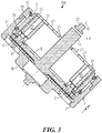
- Fig. 3 shows a further cross-section through the motor-gear unit 100 along the line of intersection marked F-F in Fig. 1 .
- the first transmitter 3 and the second transmitter 4 which are positioned between the outer wheel toothing 2 and the inner wheel toothing 7 and rotate peripherally with the transmitter carrier 5, each drag a section of the roller chain 8 into the outer wheel toothing 2, the roller chain 8 being lifted off the first 3 and second transmitters 4 by the inner wheel toothing.
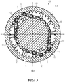
- Fig. 5 shows a cross-section along the line of intersection marked H-H in Fig. 4 .
- the first transmitter 3 and the second transmitter 4 each have a curved sickle-shaped inner face 12 facing the inner wheel toothing 7 and a convex outer face 13 which slides along on the roller chain 8.
- a disc-shaped stator plate 50 is clamped in an axially centred position between the rear housing section 9 and the central housing section 17, where it is screwed to the rear housing section 9 with fixing bolts 51 such that it is unable to rotate.
- the stator plate 50 has around its periphery a plurality of armatures 22 which lie opposite the inner casing surface of the transmitter carrier 5.
- the stators/armatures 22 are surrounded by coil windings (not shown in this view) through which an electrical current flows when the motor-gear unit 1 is in operation.
- several intermediate circuit annular capacitors 52 with capacitor connectors 54 are provided as energy accumulators for the inverter components 53 which are also provided on the stator plate 50.
- Cooling bodies 55 extending between the inverter components 53 and the inner wall of the rear housing section 9 are responsible for heat dissipation.
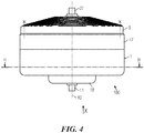
- the rear housing section 9 is provided with cooling fins which are shown most clearly in Fig. 4 .
- the stator plate 50 is provided with electrical power via supply cables 56 which run out through the rear housing section 9.
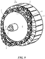
- armatures 22 Lying radially opposite the permanent magnets 21 is a number of armatures 22 which are shown most clearly in Fig. 9 .
- the armatures 22 are positioned radially around the inside of the cylindrical casing of the inner wheel 6, such that they are able to rotate about the axis of symmetry 10 together with the inner wheel 6.
- the armatures 22 are surrounded by a coil winding (not shown in this view) to which an electronic control unit (similarly not shown) applies electrical power. This generates an alternating magnetic field which interacts with the permanent magnet 21.
- the permanent magnets 21 extend a little beyond the lower edge of the transmitter carrier 5.
- sensors Fitted to the stator plate in the vicinity of the peripheral position of the permanent magnets 21 are sensors which allow the position of the transmitter carrier to be identified. In this arrangement it is possible to not only use the standard sensors such as Hall sensors, but also inexpensive optical sensors or simple induction coils in which the permanent magnets 21 generate characteristic induction currents for changes in the position of the transmitter carrier as they move past.
- the roller chain 8 has a number of bolts 23 on which are positioned rollers 24 and plates 25 which, together with the bolts 23, form a plurality of chain links.
- the external diameter of the rollers 24, the geometry of the outer wheel toothing 2 and the geometry of the inner wheel toothing 7 are designed so as to create a chain drive between the housing 1 and the inner wheel 6.
- a seal (not illustrated here) between the housing 1 and the transmitter carrier 5 ensures that the roller chain 8 as well as the sliding contact between the transmitters 3, 4 and the roller chain 8 and the bearings 14, 15, 19 receives lubrication without oil reaching the region of the stator 22, the stator plate 50 and the magnets 21.
- Figs. 6 to 15 show it in various stages of disassembly.
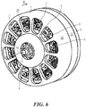
- Fig. 6 shows an angled front view of the motor-gear unit 100 in its fully assembled state. There is a clear view through the viewing panels in the holes 20 of the manner in which the gear unit complete with outer wheel toothing 2, roller chain 8, inner wheel toothing 7 and the two transmitters 3, 4 operates.
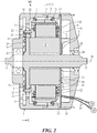
- Fig. 7 shows a view of the motor-gear unit disclosed in Fig. 6 with the front housing section 16 removed.
- the inner wheel 6 with the inner wheel toothing 6 is clearly visible.
- the oil seal on the transmitter carrier 5 in the region between the two transmitters 4, 5 has been removed in Fig. 7 giving a view of the armature stampings of the stators 22.
- Fig. 8 shows a view of the motor-gear unit 100 illustrated in Fig. 6 with the stator plate 50 removed.
- the stators 22, which are still visible in Fig. 7 are therefore no longer visible in Fig. 8 .
- the permanent magnets 21 are clearly visible on the inside of the transmitter carrier 5.
- Fig. 9 shows the stator 22 removed in Fig. 8 with the inner wheel 6 and the output shaft 11
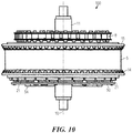
- Fig. 10 shows a top view of the stator with the inner wheel 6 as illustrated in Fig. 9 , with the transmitter carrier 5 in place and the two bearings 14, 15 and the stator plate 50 and the capacitor connectors 54.
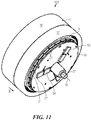
- Fig. 11 shows an angled rear view of the motor-gear unit illustrated in Fig. 1 but with the rear housing section 9 removed.
- the stator 22 is visible between the permanent magnets 21 and the stator plate 50. This stator 22 is shown particularly clearly in Fig. 12 in which the front housing section 16, the central housing section 17 and the transmitter carrier 5 have also been removed.
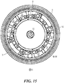
- Fig. 13 shows a view of the motor-gear unit 100 as illustrated in Fig. 11 with the central housing section 17 and stator plate 50 removed.
- Fig. 14 shows another view of the motor-gear unit 100 in the state illustrated in Fig. 10 .
- Fig. 15 shows a section through the motor-gear unit as illustrated in Fig. 14 along the line of intersection M-M.
- the transmitter carrier 5 with the two transmitters 3, 4 is clearly visible.
- the spaces between the transmitters 3, 4 are sealed against oil leakage with plastic inspection glass (not shown here).
- a gear unit is combined with an electric motor.
- the gear unit comprising the housing 1 with the outer wheel toothing 2, the inner wheel 6 with the inner wheel toothing 7 and with the output shaft 11, the roller chain 8, the transmitter carrier 5 with the first 3 and second transmitters 4 can also be used with another type of motor that is adapted to drive the transmitter carrier 5. It is in principle also possible to drive the output shaft 11 while securing either the transmitter carrier 5 or the housing 1. The output torque can then be tapped either from the housing 1 or from the transmitter carrier 5.
- Fig. 16 shows an angled top view of a further motor-gear unit 100 as disclosed in this application.
- the motor-gear unit 100 in Fig. 16 is substantially the same as the motor-gear unit 100 shown in Figs. 1 to 15 . Identical parts are given the same reference numerals.
- a first frame tube 30 and a second frame tube 3 are welded to the periphery of the front housing section 16, forming a frame of a two-wheeled vehicle (not illustrated here).
- the output shaft 11 drives a rear wheel of the vehicle (not shown here).
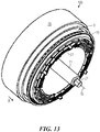
- Fig. 18 shows a further motor-gear unit 100 which is designed as a wheel hub motor of a vehicle not shown here in full. Parts which are the same as those in the motor-gear unit 100 shown in Figs. 1 to 17 have the same reference numerals or the same reference numerals followed by an apostrophe in the case of parts with the same function but a different form.
- the output shaft 11' is fixed. It is mounted on two square ends 65 in wishbone tubes of a vehicle (not illustrated here).
- a rear shaft nut 64 tightens the rear housing section 9' onto a shaft projection 66 on the output shaft 11'.
- a front shaft nut 63 sets the play of the bearing 19', 60 by means of which the front housing section 16' and the central housing section 17' are mounted such that they are able to rotate on the output shaft 11' or the rear housing section 9'.
- Figs. 19 to Fig. 22 illustrate the function of the harmonic chain gear disclosed in the application.
- links in the roller chain 8 are dragged or lifted successively peripherally by the first 4 and second transmitters 4 into the outer wheel toothing 2.
- the front housing section 16 is fixed to the outer wheel toothing 2. This is indicated by the letter "B" marked on the top of the front housing section 16 which is fixed in Figs. 19 to 22 .
- the inner wheel 6 may be driven by the electric motor and to fix either the transmitter carrier 5 or the outer wheel 1.
- the outer wheel 1 When the outer wheel 1 is fixed, output is via the transmitter carrier 5. Conversely, if the transmitter carrier 5 is fixed, output is via the outer wheel 1. In these designs it is necessary to pay particular attention to the friction characteristics in the region of the roller chain 8 to avoid self-inhibiting.
- the electric motor can also drive the outer wheel 1 with output being either via the transmitter carrier 5 or the inner wheel 6, depending on whether the inner wheel 6 or the transmitter carrier 5 is fixed.
- the transmitter carrier 5 is set in rotation by forces acting on the permanent magnets 21.
- the outside of a first chain 87 of the double chain 8' is thus drawn into the outer wheel toothing 2 by means of the gear wheels 80, 81.
- the inside of the first chain 87 of the double chain 8' is engaged with the inner wheel toothing 7 and the inner wheel 6 and, thus, the output shaft 11 are therefore driven in the manner previously shown in Figs. 19 to 22 .
- gear wheels 80, 81 it is also possible to use rollers which push the inside of the second chain 82 outwards.
- the rollers and, in particular, the gear wheels 80, 81 are able to deflect the forces which occur along the periphery of the chain 8'. This leads to lower friction losses when the chain 8' is drawn into the external teeth 2.
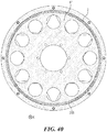
- a transmitter carrier with transmitters which is arranged inside the pin ring 308, revolves around the axis 10.
- the 25 transmitters push against the flexible inner ring of the pin ring 308 and, in two opposing dragger regions, lift the pins of the pin ring from the inner wheel/wheels.
- the pins 305 of the pin row are pushed between the teeth of the outer wheel toothing/toothings.
- the pins 305 in turn exert a lateral force against the outer wheel toothing/toothings such that the outer wheel turns.
- the transmitters are realized as circular or oval shaped dragger disks or dragger rings and the transmitter carriers are realized as a support on which the transmitter are fixed.
- a bearing which takes up the friction can be seen as part of the transmitter for those embodiments which provide a flexible bearing between the dragger disks and the outer wheel toothing and as part of the transmitter carrier in the embodiments in which the dragger disks are supported on the bearing from the inside.
- Synchronous motors which can be operated in parallel have a torque curve which is largely constant in relation to speed. Conversely, the available torque of a synchronous motor operated in series rises as speed increases.
- Motors with series connection behaviour are therefore particularly suitable for the subject matter of the application because operating without switchgear, i.e. with a fixed speed reduction, is possible over a wide speed range.
- DC series motors which develop a very high speed at low load, but in which the speed then drops sharply as load increases, have proved particularly successful. They produce a high-speed drive with high starting torque which is particularly desirable when driving vehicles.
- a series motor and in particular a DC series motor has a high torque which permits high starting acceleration. The speed can reach very high levels entirely without load.
- An electronic control unit advantageously counters this by reducing power through the application of a lower drive voltage to the motor.
- both double and single split axial motors are possible.
- a radial motor with an inner rotor or an outer rotor is also conceivable.
- Outer rotors have the advantage of a higher moment of inertia which has a favourable effect on the running smoothness of the drive unit it forms.
- Combinations of axial motors and radial motors are also conceivable, in particular when they are designed as outer rotors.
- the gear can also be employed to use a high-speed drive unit such as an internal combustion engine or a gas or fuel combustion turbine to drive a generator at a relatively low speed.
- a high-speed drive unit such as an internal combustion engine or a gas or fuel combustion turbine to drive a generator at a relatively low speed.
- the pressure means may be designed as a flexible metal sheath which is able to transmit thrust forces and bending moments. Where this is the case the transmitters lie against the outside of the sheath and drag it from tooth to tooth.
- the subject matter of the application also relates to a harmonic chain gear in which the transmitters are mounted on shafts such that they are able to rotate and the shafts are provided on the transmitter carrier. In this arrangement, the transmitters may be designed as gear wheels or rollers.
- the traction means respectively the pressure means has one single radial section that is provided both for the contact with the outer wheel and for the inner wheel.
- the transmitter generally contacts the traction means respectively the pressure means from within the gap between the inner wheel and the outer wheel.
- the transmitter, the inner wheel, the outer wheel as well as the traction means respectively the pressure means are located essentially in the same axial plane.
- the inner wheel and the outer wheel are often located in different axial planes, wherein the transmitter is either located in the axial plane of the inner wheel or in the axial plane of the outer wheel.
- the traction means respectively the pressure means extends axially between the axial planes of the inner wheel and the outer wheel, contacting both the inner wheel and the outer wheel at different sections of their respective circumferences.
- the two pairs of an inner wheel and an outer wheel are located in different axial planes, wherein the transmitter is located in a third axial plane between the two pairs of an inner wheel and an outer wheel.
- a three row gear design with one inner wheel and one outer wheel.
- a double row transmitter with two transmitter sections, wherein each transmitter section is provided in an axial plane which is different from the axial plane of the inner wheel.
- the traction means respectively the pressure means extends axially between the axial planes of the outer wheels and the inner wheel, contacting both the inner wheel and the outer wheels at different sections of their respective circumferences.
Description
- The present application relates to a gear having an input shaft and an output shaft. More particularly, the present application relates to a motor-gear unit with such a gear and to a motor vehicle with such a motor-gear unit. The present application also relates to an electric generator with a drive unit such as an internal combustion engine or such as a propeller for water or wind, further having a generator unit for generating electricity and having a gear in accordance with the application.
- The
US 4,023,440 A discloses, in itsFigs. 6 and7 , anendless belt 25 for a gear, which as a multitude ofpins 21 that stand proud of a first axial surface of the belt in a first axial direction of the belt and of a second axial surface of the belt in a second axial direction which is opposite to the first direction. The pins are essentially coaxially arranged with the belt. - The
GB 2337973 A Figs. 4 and5 , abelt 62 for a conveyor drive withpins 28 that stand proud of a first axial surface of the belt in a first axial direction of the belt and of a second axial surface of the belt in a second axial direction which is opposite to the first direction. - The
JP 2007-205397 A Figs. 4 to 6 , a flexible spline for a harmonic drive which has a multitude of cylindricalgear tooth components 24 which stand proud of aring member 25 in an axial direction. The gear tooth components are coaxially arranged with the flexible spline. As shown inFig. 2 of this document, an inner surface of the flexible spline is suitable for supporting a flexible ball bearing. -
Claim 1 defines the invention for which protection is sought and claims a flexible spline element. Dependent claims 2-3 concern particular embodiments of the claimed flexible spline element. Dependent claims 4-7 concern a gear, a motor-gear, a vehicle and an electric generator, each comprising the flexible spline element claimed inclaim 1. - The present application provides an improved gear, motor-gear unit, vehicle, generator with a gear, and force transmitting element.
- The gear has an input shaft and an output shaft and also an outer wheel and an inner wheel which is positioned concentrically in relation to the outer wheel and often inside the outer wheel. There is also a ring-shaped or cylindrical or elliptic traction provided that extends between the outer wheel and the inner wheel. A revolving transmitter lifts or drags the traction means away from the outer periphery of the inner wheel and pushes it onto the inner periphery of the outer wheel. This is a simple and reliable setup for a gearbox which can provide high gear ratios.
- There are many ways for connecting the input shaft and the output shaft to the gear. It is especially advantageous to connect the input shaft to the transmitter and to connect the output shaft is to the inner wheel or to the outer wheel. The wheel which is not connected to the output shaft needs then to be kept steady or connected with a housing of the gear.
- Alternatively, one can also connect the input shaft with the outer wheel or the inner wheel, while the output shaft is connected to the transmitter. The wheel which is not connected to the input shaft needs then to be kept steady or connected with a housing of the gear. This arrangement needs to be carefully designed in order to avoid self-locking of the transmitter but this is especially useful for converting high input torques from slow power sources into high rotational frequencies as often needed by electrical generators.
- The traction means can be provided as a closed chain of rotatably interconnected links such as a bolt chain or a roller chain.
- It is not only possible to provide the chain as a single chain nut also as a double or triple chain. One advantage of such a double chain or triple chain is that the transmitter can be provided in an axial plane that is different from the axial planes of the inner wheel or outer wheel. Higher gear ratios can then be provided.
- The gear can be provided as a one row gear design wherein the traction means has one single radial section that is provided both for the contact with the outer wheel and for the inner wheel. In the one row gear design, the transmitter often contacts the traction means from within the gap between the inner wheel and the outer wheel. The transmitter, the inner wheel, the outer wheel as well as the traction means respectively the pressure means are located essentially in the same axial plane which makes the design axially symmetric.
- In an axially asymmetric two row gear design, the inner wheel and the outer wheel are often located in different axial planes, wherein the transmitter is either located in the axial plane of the inner wheel or in the axial plane of the outer wheel. The traction means then extends axially between the axial planes of the inner wheel and the outer wheel, contacting both the inner wheel and the outer wheel at different sections of their respective circumferences.
- In a three row gear design, the two pairs of an inner wheel and an outer wheel are often located in different axial planes, wherein the transmitter is located in a third axial plane between the two pairs of an inner wheel and an outer wheel. One can also think of a three row gear design with two inner wheels and one outer wheel or - alternatively - also with two outer wheels and one inner wheel. In a further alternative, it is also possible to provide a double row transmitter with two transmitter sections, wherein each transmitter section is provided in an axial plane which is different from the axial plane of the inner wheel. The traction means then extends axially between the axial planes of the outer wheels and the inner wheel, contacting both the inner wheel and the outer wheels at different sections of their respective circumferences.
- It is also possible to provide a axially symmetric three row gear design with two outer wheels and one inner wheel, that are located in different axial planes, wherein the transmitter is located in the axial plane of the inner wheel. It is then also possible to provide a double row transmitter with two transmitter sections, wherein each transmitter section is provided in the axial plane of each outer wheel. The traction means then extends axially between the axial planes of the inner wheels and the outer wheel, contacting both the inner wheels and the outer wheel at different sections of their respective circumferences.
- The traction means may also comprise at least one continuous elliptic traction element that can also be a deformable circular ring or cylinder. Such a traction means is easy to manufacture, especially if the traction element is provided in the form of a flexible belt, possibly with teeth. Such a traction element is often made from plastic or rubber which provided on a metal meshing or a woven or non-woven fabric.
- In a very advantageous form, the traction element comprises a thin and flexible spline element, that is possibly provided with teeth and it can also be made from plastic. The flexible spline element may comprise a multitude of pins that stand proud of or protrude from at least one axial surface of the spline element and that are coaxially arranged with the flexible spline element. With such a traction element, extremely high gear ratios can be achieved because the difference between the diameter of the outer wheel and the diameter of the inner wheel can be made almost as small as the diameter of the pins.
- The transmitter or the transmitters may be positioned on a rotatable transmitter carrier by mounting them concentrically in relation to the outer wheel and the inner wheel. As said before, the transmitter carrier is preferably connected to the input shaft or to the output shaft for achieving high transmission ratios.
- The transmitters can be each mounted on a shaft such that they are able to rotate while the shafts are provided on the transmitter carrier. Alternatively, the transmitter may be fixed to the transmitter carrier, wherein the traction means comprises a multitude of rotatable contact elements such as rollers on chain bolts.
- It also possible to provide the transmitters eccentrically from the rotation axis of the transmitter carrier such that the rotation axis of the transmitter is positioned off the rotation axis of the transmitter carrier. This provides for new shapes of the outer surface of the transmitters that are easy to manufacture.
- Alternatively, the rotation axis of the transmitter may essentially coincide with the rotation axis of the transmitter carrier, wherein a contact surface of the transmitter facing towards the traction means is provided with an essentially elliptic shape. Providing an essentially elliptic shape includes that a non-circular flat surface is provided which is round such that a bearing or a number of balls can be arranged between the contact surface and the traction means.
- In one possible use of the gear, an electric motor is provided, a rotor of the electric motor being connected to the input shaft of the gear. For lightweight vehicles, often a DC brushless motor with a radial gap is provided, but other types of motors and also internal combustion engines apply as well, as described below with the embodiments. The DC brushless motor is easy to provide with the gear of the application because the gear housing can be the motor housing at the same time.
- A vehicle, in particular a two- or three-wheeled vehicle, can be equipped with such a motor-gear unit, wherein at least one driven wheel of the vehicle is connected to the output shaft of the gear.
- The gear may also be used for an electric generator with a drive unit such as an internal combustion engine or a propeller for water or wind and with a generator unit for generating electricity. An input shaft of the gear is then connected to the drive unit and an output shaft of the gear being connected to an input shaft of the generator.
- An advantageous transmitter assembly for contacting a traction means in a gear comprises one or more first transmitter elements and one or more a second transmitter elements that are provided on a rotatable transmitter carrier that is mounted concentrically in relation to the outer wheel and the inner wheel and that is preferably being connected to the input shaft or to the output shaft for achieving high transmission ratios. The transmitter elements are each mounted on a shaft such that they can rotate on the transmitter carrier. The first transmitter element and the second transmitter element are provided eccentrically from the rotation axis of the transmitter carrier. Such an arrangement allows for new shapes of the transmitter which provides some extra degrees of freedom for the design of a gear.
- It is then possible to tighten or tension the transmitter with the two transmitter elements by shifting them with respect to each other. A guide for shifting the first transmitter element with respect to the second transmitter element may therefore be provided, as well as transmitter adjustment slits with a guiding element, the guiding elements being either provided in carrier adjustment slits in the transmitter carrier or the guiding elements being taken up by guiding slits in adjacent transmitter elements.
- In an alternative form, the gear of the application is provided with an input shaft and with an output shaft, wherein the at least one revolving transmitter pushes the pressure means away from the inner periphery of the outer wheel and pushes the pressure means onto the outer periphery the inner wheel. This gear is very similar to the other alternative where the transmitter shifts the traction means away from the outer periphery of the inner wheel into the inner periphery the outer wheel. Most of the design elements of the other gear can be used for the gear with the pressure means, except that the pressure means needs to be able to transmit compressive forces. This is why many chains with movable links cannot be used as a pressure means.
- The application also provides a thin and flexible spline element for a gear, the spline element comprising a multitude of pins that stand proud of or protrude from at least one axial surface of the spline element and that are coaxially arranged with the flexible spline element. The multitude of pins may also stand proud of both axial surfaces of the spline element. A flexible spline element in which the multitude of pins are provided in a multitude of axial cylindrical orifices is easy to manufacture. It has turned out that it is advantageous to make the pins from steel, that is later hardened, and the spline element from aluminium.
- The embodiments of the application are explained in further detail with reference to the following figures, in which
- Fig. 1
- shows a front view of a motor-gear unit as disclosed in the application,
- Fig. 2
- shows a section through the motor-gear unit illustrated in
Fig. 1 along the line of intersection marked J-J inFig. 1 , - Fig. 3
- shows a section through the motor-gear unit illustrated in
Fig. 1 along the line of intersection marked F-F inFig. 1 , - Fig. 4
- shows a top view of the motor-gear unit illustrated in
Fig. 1 , - Fig. 5
- shows a section through the motor-gear unit illustrated in
Fig. 4 along the line of intersection H-H, - Fig. 6
- shows an angled front view of the motor-gear unit illustrated in
Fig. 1 , - Fig. 7
- shows a view of the motor-gear unit illustrated in
Fig. 6 with the outer wheel cover removed, - Fig. 8
- shows a further view of the motor-gear unit illustrated in
Fig. 6 , - Fig. 9
- shows a stator with an inner wheel carrier and inner wheel of the motor-gear unit as illustrated in
Fig. 6 , - Fig. 10
- a top view of the stator with inner wheel carrier and inner wheel illustrated in
Fig. 9 with the transmitter carrier in place, - Fig. 11
- shows an angled rear view of a motor-gear unit as illustrated in
Fig. 1 , - Fig. 12
- shows a view of the motor-gear unit illustrated in
Fig. 11 with the outer wheel removed, - Fig. 13
- shows a further view of the motor-gear unit illustrated in
Fig. 11 , - Fig. 14
- shows a view of the motor-gear unit disclosed in
Fig. 11 with the outer wheel removed, - Fig. 15
- shows a section through the motor-gear unit illustrated in
Fig. 14 along a plane of intersection M-M, - Fig. 16
- shows an angled rear view of a further motor-gear unit as disclosed in the application which is integrated in a vehicle frame,
- Fig. 17
- shows a view of a further motor-gear unit,
- Fig. 18
- shows a top view of a further motor-gear unit with a chain pinion fitted,
- Figs. 19 to Fig. 22
- illustrate the function of the harmonic chain gear disclosed in the invention,
- Fig. 23
- shows a harmonic chain gear as disclosed in one embodiment with a double chain,
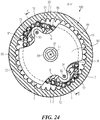
- Fig. 24
- shows a view of a harmonic chain gear as disclosed in an embodiment with a triple chain,
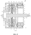
- Fig. 25
- shows the harmonic chain gear illustrated in
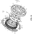
Fig. 24 along the cross-section marked F-F inFig. 24 , - Fig. 26
- shows an exploded drawing of a further embodiment of a harmonic chain gear with a double chain,
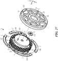
- Fig. 27
- shows an exploded drawing of a further embodiment of a harmonic chain gear,
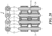
- Fig. 28
- shows a cut-out of a double roller chain,
- Fig. 29
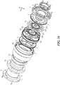
- shows a partial-exploded drawing of a further embodiment of a motor-gear unit,
- Fig. 30
- shows an exploded drawing of the gear parts omitted in
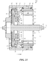
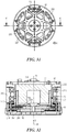
Fig. 29 , - Fig. 31
- shows a view of the motor-gear unit in
Fig. 29 , - Fig. 32
- shows a section through the motor-gear unit in
Fig. 29 , - Fig. 33
- shows a side view of the motor-gear unit in
Fig. 29 , - Fig. 34
- shows a further section through the motor-gear unit in
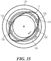
Fig. 29 , - Fig. 35
- shows a version of the previous embodiments with a pressure means,
- Fig. 36
- shows an exploded view of an embodiment of a harmonic chain drive with a two-pin-row pin ring,
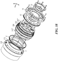
- Fig. 37
- shows a cross-section through the motor-gear unit of
Fig. 36 , - Fig. 38
- shows an exploded view of an embodiment of a harmonic chain drive with a two-pin-row pin ring and with a wire race bearing,
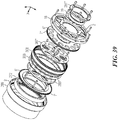
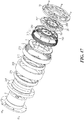
- Fig. 39
- shows an exploded view of an embodiment of a harmonic chain drive with a two-pin-row pin ring and with und two oval dragger disks,
- Fig. 40
- shows a cross-section through the motor-gear unit as shown in
Fig. 38 orFig. 39 , - Fig. 41
- shows a cross-section through the motor-gear unit as shown in
Fig. 36 , - Fig. 42
- shows a cross-section through the motor-gear unit as shown in
Fig. 37 , - Fig. 43
- shows a cross-section through the motor-gear unit as shown in
Fig. 38 , - Fig. 44
- shows a partial cross-section through the motor-gear unit as shown in
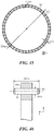
Fig. 37 , - Fig. 45
- shows a side view of a pin ring,
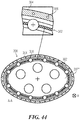
- Fig. 46
- shows a cross section through an element of the pin ring,
- Fig. 47
- shows an exploded view of an embodiment of a harmonic chain drive with a tooth belt
- Fig. 48
- shows a first cross-section through the harmonic chain drive of
Fig. 47 , and - Fig. 49
- shows a second cross-section through the harmonic chain drive of
Fig. 47 . -
Figs. 1 to 15 show a first motor-gear unit 100 as disclosed in this application. - As is shown most clearly in
Fig. 2 , which shows a cross-section through the motor-gear unit 100 disclosed in this application along the line of intersection marked J-J inFig. 1 , said motor-gear unit 100 is divided into a cup-shapedhousing 1, aninner wheel 6 which is provided in this case in one piece on anoutput shaft 11 mounted in thehousing 1 such that it is able to rotate, and aroller chain 8 which is guided between thehousing 1 and theinner wheel 6 by atransmitter carrier 5 which is mounted in thehousing 1 such that it is able to rotate. - As can clearly be seen in
Fig. 1 , thehousing 1 has on its inside radially inward facingouter wheel toothing 2, while theinner wheel 6 has radially outward facinginner wheel toothing 7. Theroller chain 8 is designed such that it engages in a form-fitting connection with both theouter wheel toothing 2 and theinner wheel toothing 7. - The
transmitter carrier 5 itself is most clearly illustrated inFig. 3 , which shows a further cross-section through the motor-gear unit 100 along the line of intersection marked F-F inFig. 1 . - The
first transmitter 3 and thesecond transmitter 4 which are positioned between theouter wheel toothing 2 and theinner wheel toothing 7 and rotate peripherally with thetransmitter carrier 5, each drag a section of theroller chain 8 into theouter wheel toothing 2, theroller chain 8 being lifted off the first 3 andsecond transmitters 4 by the inner wheel toothing. - The dragging or lifting of the
roller chain 8 by the first 3 andsecond transmitters 4 is illustrated inFig. 5 which shows a cross-section along the line of intersection marked H-H inFig. 4 . For this purpose thefirst transmitter 3 and thesecond transmitter 4 each have a curved sickle-shapedinner face 12 facing theinner wheel toothing 7 and a convexouter face 13 which slides along on theroller chain 8. - The
transmitter carrier 5 is designed as a cylindrical body which is mounted in thehousing 1 on a frontradial bearing 14 and a rearradial bearing 15, such that it is able to rotate about an axis ofsymmetry 10 of the motor-gear unit 100. In this arrangement, thetransmitter carrier 5 is designed as one piece with the first 3 andsecond transmitters 4 as is illustrated most clearly inFig. 3 . - To simplify the assembly of the bearing of the
transmitter carrier 5, thehousing 1 is made of two parts: a cup-shapedfront housing section 16 and a cylindricalcentral housing section 17 which mate radially with one another. In this arrangement thefront housing section 16 has a forwards extendingbearing support 18 in which is positioned a frontoutput shaft bearing 19.Holes 20 in the region between the radial outer part of thefront housing section 16 and the bearingsupport 18 are shown most clearly inFig. 6 . A total of 12such holes 20 is provided. They are sealed with transparent plastic panels (not illustrated) against oil leakage. These transparent panels provide a view of the oil level in the housing and can be used to monitor the operation of the motor-gear unit 100. - The side of the
housing 1 axially opposite thefront housing section 16 is closed by a cup-shapedrear housing section 9 which has a receivingopening 28 for a rear output shaft bearing 26 in which theoutput shaft 11 is mounted such that it is able to rotate. - A disc-shaped
stator plate 50 is clamped in an axially centred position between therear housing section 9 and thecentral housing section 17, where it is screwed to therear housing section 9 with fixingbolts 51 such that it is unable to rotate. Thestator plate 50 has around its periphery a plurality ofarmatures 22 which lie opposite the inner casing surface of thetransmitter carrier 5. In this arrangement the stators/armatures 22 are surrounded by coil windings (not shown in this view) through which an electrical current flows when the motor-gear unit 1 is in operation. In addition, several intermediate circuit annular capacitors 52 withcapacitor connectors 54 are provided as energy accumulators for theinverter components 53 which are also provided on thestator plate 50. Coolingbodies 55 extending between theinverter components 53 and the inner wall of therear housing section 9 are responsible for heat dissipation. In this arrangement therear housing section 9 is provided with cooling fins which are shown most clearly inFig. 4 . - The
stator plate 50 is provided with electrical power viasupply cables 56 which run out through therear housing section 9. - Positioned on the inside or on the inner casing surface of the cylindrical transmitter carrier 5 - and distributed around the periphery of the transmitter carrier 5 - is a plurality of
permanent magnets 21. Thesepermanent magnets 21 are shown most clearly inFig. 3 which illustrates a section through the motor-gear unit 100 shown inFig. 1 along the line of intersection F-F. Therear housing section 9 and other components of the motor-gear unit 100 are removed inFig. 3 . In this arrangement thepermanent magnets 21 are designed as parts of the casing surface of an imagined cylinder, such that they lie flush with the inner casing surface of thetransmitter carrier 5. Due to the presence of thesepermanent magnets 21 the transmitter carrier becomes the rotor of an electric motor. - Lying radially opposite the
permanent magnets 21 is a number ofarmatures 22 which are shown most clearly inFig. 9 . Thearmatures 22 are positioned radially around the inside of the cylindrical casing of theinner wheel 6, such that they are able to rotate about the axis ofsymmetry 10 together with theinner wheel 6. In this arrangement thearmatures 22 are surrounded by a coil winding (not shown in this view) to which an electronic control unit (similarly not shown) applies electrical power. This generates an alternating magnetic field which interacts with thepermanent magnet 21. - As is shown particularly clearly in
Fig. 3 , thepermanent magnets 21 extend a little beyond the lower edge of thetransmitter carrier 5. Fitted to the stator plate in the vicinity of the peripheral position of thepermanent magnets 21 are sensors which allow the position of the transmitter carrier to be identified. In this arrangement it is possible to not only use the standard sensors such as Hall sensors, but also inexpensive optical sensors or simple induction coils in which thepermanent magnets 21 generate characteristic induction currents for changes in the position of the transmitter carrier as they move past. - As shown particularly clearly in
Fig. 2 , theroller chain 8 has a number ofbolts 23 on which are positionedrollers 24 andplates 25 which, together with thebolts 23, form a plurality of chain links. In this arrangement the external diameter of therollers 24, the geometry of theouter wheel toothing 2 and the geometry of theinner wheel toothing 7 are designed so as to create a chain drive between thehousing 1 and theinner wheel 6. - In this arrangement a seal (not illustrated here) between the
housing 1 and thetransmitter carrier 5 ensures that theroller chain 8 as well as the sliding contact between thetransmitters roller chain 8 and thebearings stator 22, thestator plate 50 and themagnets 21. - To give a better understanding of the structure of the motor-
gear unit 100Figs. 6 to 15 show it in various stages of disassembly. -
Fig. 6 shows an angled front view of the motor-gear unit 100 in its fully assembled state. There is a clear view through the viewing panels in theholes 20 of the manner in which the gear unit complete withouter wheel toothing 2,roller chain 8,inner wheel toothing 7 and the twotransmitters -
Fig. 7 shows a view of the motor-gear unit disclosed inFig. 6 with thefront housing section 16 removed. Theinner wheel 6 with theinner wheel toothing 6 is clearly visible. The oil seal on thetransmitter carrier 5 in the region between the twotransmitters Fig. 7 giving a view of the armature stampings of thestators 22. -
Fig. 8 shows a view of the motor-gear unit 100 illustrated inFig. 6 with thestator plate 50 removed. Thestators 22, which are still visible inFig. 7 , are therefore no longer visible inFig. 8 . As a result, thepermanent magnets 21 are clearly visible on the inside of thetransmitter carrier 5. -
Fig. 9 shows thestator 22 removed inFig. 8 with theinner wheel 6 and theoutput shaft 11, andFig. 10 shows a top view of the stator with theinner wheel 6 as illustrated inFig. 9 , with thetransmitter carrier 5 in place and the twobearings stator plate 50 and thecapacitor connectors 54. -
Fig. 11 shows an angled rear view of the motor-gear unit illustrated inFig. 1 but with therear housing section 9 removed. Thetransmitter carrier 5 with the projectingpermanent magnets 21, which pass flush by the stator plate, is clearly visible. Thestator 22 is visible between thepermanent magnets 21 and thestator plate 50. Thisstator 22 is shown particularly clearly inFig. 12 in which thefront housing section 16, thecentral housing section 17 and thetransmitter carrier 5 have also been removed. -
Fig. 13 shows a view of the motor-gear unit 100 as illustrated inFig. 11 with thecentral housing section 17 andstator plate 50 removed. -
Fig. 14 shows another view of the motor-gear unit 100 in the state illustrated inFig. 10 . -
Fig. 15 shows a section through the motor-gear unit as illustrated inFig. 14 along the line of intersection M-M. Thetransmitter carrier 5 with the twotransmitters transmitters - When the motor-
gear unit 100 illustrated inFigs. 1 to 15 is in operation the chain drive with thehousing 1, theinner wheel 6 and theroller chain 8 is actuated as follows. An alternating voltage is applied in an appropriate manner to the coil windings (not shown here) around thearmatures 22 so as to create an alternating electromagnetic field which cooperates with thepermanent magnets 21. In this arrangement an electronic control device (of which the inverter components and the intermediate circuit annular capacitors are shown here) ensures that the alternating electromagnetic field sets thetransmitter carrier 5 in rotation about the axis ofsymmetry 10. The first 3 andsecond transmitters 4 move together with thetransmitter carrier 5 in a circular direction about the axis ofsymmetry 10. - As is seen most clearly in
Fig. 5 , in this arrangement links in theroller chain 8 are pushed consecutively peripherally towards theouter wheel toothing 2. In the process, the subsequent chain strand in the peripheral direction of thetransmitter carrier 5 pulls the inner wheel after it. In these circumstances the difference in radius between theouter wheel toothing 2 and theinner wheel toothing 7 results in a predetermined transmission ratio. - In the above described embodiment, a gear unit is combined with an electric motor. The gear unit, comprising the
housing 1 with theouter wheel toothing 2, theinner wheel 6 with theinner wheel toothing 7 and with theoutput shaft 11, theroller chain 8, thetransmitter carrier 5 with the first 3 andsecond transmitters 4 can also be used with another type of motor that is adapted to drive thetransmitter carrier 5. It is in principle also possible to drive theoutput shaft 11 while securing either thetransmitter carrier 5 or thehousing 1. The output torque can then be tapped either from thehousing 1 or from thetransmitter carrier 5. -
Fig. 16 shows an angled top view of a further motor-gear unit 100 as disclosed in this application. The motor-gear unit 100 inFig. 16 is substantially the same as the motor-gear unit 100 shown inFigs. 1 to 15 . Identical parts are given the same reference numerals. In this arrangement afirst frame tube 30 and asecond frame tube 3 are welded to the periphery of thefront housing section 16, forming a frame of a two-wheeled vehicle (not illustrated here). Theoutput shaft 11 drives a rear wheel of the vehicle (not shown here). -
Fig. 17 shows a view of a further motor-gear unit which has substantially the same parts as the motor-gear unit shown in the previous figures. Identical parts are given the same reference numerals. - In this arrangement a trailing or driven wheel 33 intended to take a tyre of a two-wheeled vehicle is screwed to the
output shaft 11. The trailing wheel 33 is provided with a freewheeling device or free-wheel 57. - As is shown particularly clearly in
Fig. 17 , a firsttransverse link 34 and a second transverse link 35a) are fixed to thefront housing section 16. -
Fig. 18 shows a further motor-gear unit 100 which is designed as a wheel hub motor of a vehicle not shown here in full. Parts which are the same as those in the motor-gear unit 100 shown inFigs. 1 to 17 have the same reference numerals or the same reference numerals followed by an apostrophe in the case of parts with the same function but a different form. - In contrast to the preceding embodiments the output shaft 11' is fixed. It is mounted on two square ends 65 in wishbone tubes of a vehicle (not illustrated here). A
rear shaft nut 64 tightens the rear housing section 9' onto ashaft projection 66 on the output shaft 11'. On the opposite side of the output shaft 11', afront shaft nut 63 sets the play of thebearing 19', 60 by means of which the front housing section 16' and the central housing section 17' are mounted such that they are able to rotate on the output shaft 11' or the rear housing section 9'. - In this arrangement the front housing section 16' and the central housing section 17' are each provided with a
rim flange 62, thereby forming a rim upon which thetyre 61 is placed. - The
tyre 61 is therefore driven via the front housing section 16' and the central housing section 17' while the output shaft 11' is fixed in thewishbone tubes 64. -
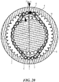
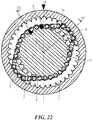
Figs. 19 to Fig. 22 illustrate the function of the harmonic chain gear disclosed in the application. In this arrangement links in theroller chain 8 are dragged or lifted successively peripherally by the first 4 andsecond transmitters 4 into theouter wheel toothing 2. - In this case, the
front housing section 16 is fixed to theouter wheel toothing 2. This is indicated by the letter "B" marked on the top of thefront housing section 16 which is fixed inFigs. 19 to 22 . - The
transmitters transmitter carrier 5 which rotates clockwise. InFig. 19 thesecond transmitter 4 stands at a position of -35° (degrees), inFig. 20 thesecond transmitter 4 stands at a position of 2°(degrees), inFig. 21 thesecond transmitter 4 stands at a position of +25° (degrees) and inFig. 22 thesecond transmitter 4 stands at a position of +53° (degrees). - In the process the chain strand of the
roller chain 8 following thesecond transmitter 4 in the peripheral direction of thetransmitter carrier 5 pulls theinner wheel 6 with it. This is indicated by means of the letter "C" marked on theinner wheel 6 and the letter "A" marked on theroller chain 8. - When the
second transmitter 4 moves clockwise from a position of -35° (degrees) inFig. 19 to a position of +53° (degrees) inFig. 22 , theinner wheel 6 moves by an angle of approx. 30° (degrees) anticlockwise. - In these circumstances the difference in radius between the
outer wheel toothing 2 and theinner wheel toothing 7 results in a predetermined transmission ratio of approx. 3:1. - In the application, output can be achieved in several manners. Firstly, the
outer wheel 1 can be fixed as is the case in the embodiments illustrated inFigs. 1 to 17 . Here output is via theinner wheel 6 when the electric motor is driving thetransmitter carrier 5. Alternatively, theinner wheel 6 can be fixed as in the embodiment illustrated inFig. 18 . In this case output is via theouter wheel 1 when the electric motor is driving thetransmitter carrier 5. - Alternatively it is also conceivable for the
inner wheel 6 to be driven by the electric motor and to fix either thetransmitter carrier 5 or theouter wheel 1. When theouter wheel 1 is fixed, output is via thetransmitter carrier 5. Conversely, if thetransmitter carrier 5 is fixed, output is via theouter wheel 1. In these designs it is necessary to pay particular attention to the friction characteristics in the region of theroller chain 8 to avoid self-inhibiting. - Self-inhibiting or self-locking can be avoided by means of the appropriate design of the sliding surfaces of the
roller chain 8, and also by means of friction-reducing measures such as lubrication or additional bearings in thetransmitters - Accordingly the electric motor can also drive the
outer wheel 1 with output being either via thetransmitter carrier 5 or theinner wheel 6, depending on whether theinner wheel 6 or thetransmitter carrier 5 is fixed. - The
roller chain 8 can be replaced by other traction or pressure means, for example by a toothed belt which can also be provided with teeth on both sides. A similar design will be illustrated with respect toFigures 47 - 49 . Instead of a form-fit as in the embodiments, whereby teeth on the wheels engage in gaps in the roller chain, a form-fit with teeth in the traction or pressure means engaging in gaps in the inner wheel or outer wheels is possible. Finally, it is also conceivable to use a friction connection between the corresponding wheels and the traction or pressure means. -
Fig. 23 shows a cross-section F-F of a further motor-gear unit 100 which is designed as a wheel hub motor of a vehicle (not illustrated in full). Parts which corresponds to parts in the previousFigs. 1 to 22 have the same reference numerals. The section is labelled F-F since the orientation of the cross-section is the same as inFig. 3 in which thechain 8 is lifted off theinner wheel 6. - In comparison to
Fig. 3 , thetransmitter carrier 5 is extended by a cup-shapedregion 79 on the side of theinner wheel 6. - Provided on the cup-shaped
region 79 are twoshafts symmetry 10. Twogear wheels ball bearings shafts gear wheels transmitters Fig. 3 . Thegear wheels second chain 82 of adouble chain 8'. Thesecond chain 82 is indicated by means of abroken line 90. The twoshafts symmetry 10 and are the same distance from the axis ofsymmetry 10. In the embodiment illustrated inFig. 23 this distance is smaller than the radius of theinner wheel 6. - As described above, in operation the
transmitter carrier 5 is set in rotation by forces acting on thepermanent magnets 21. The outside of afirst chain 87 of thedouble chain 8' is thus drawn into theouter wheel toothing 2 by means of thegear wheels first chain 87 of thedouble chain 8' is engaged with theinner wheel toothing 7 and theinner wheel 6 and, thus, theoutput shaft 11 are therefore driven in the manner previously shown inFigs. 19 to 22 . - The use of a
double chain 8' allows thegear wheels inner wheel 6. Thus the optimum size can be chosen for thegear wheels larger gear wheels gear wheels chain 8' and between thechain 8' and theouter wheel toothing 2. The forces occurring are thus more evenly distributed and the load on thechain 8' and theouter wheel toothing 2 reduced. In addition, it is possible to make the distance between theinner wheel toothing 7 and theouter wheel toothing 2 smaller. This means that it is possible to achieve higher speed-reduction at a given tooth size. - Instead of the
gear wheels second chain 82 outwards. The rollers and, in particular, thegear wheels chain 8'. This leads to lower friction losses when thechain 8' is drawn into theexternal teeth 2. -
Figs. 24 and35 show a further embodiment in which atriple chain 8'' is provided in place of thedouble chain 8' as shown inFig. 23 . Elements already shown inFig. 23 are not reiterated. The sectional plane H'-H' shown inFig. 24 is positioned parallel to the corresponding sectional plane H-H shown inFig. 4 and offset towards theoutput shaft 11. - A
transmitter disc 90 is mounted on theoutput shaft 11 such that it is able to rotate freely. Provided in thetransmitter disc 90 are twoshafts gear wheel gear wheels symmetry 10 and engage in athird chain 88 of thetriple chain 8'' from within. Thetransmitter disc 90 is cut out in the area of theshafts inner wheel 6 remains free. In the centre of thetransmitter disc 90, a circular opening is left free around the output shaft. Twoouter regions transmitter disc 90 are located outside the periphery of theinner wheel toothing 7 and are connected rigidly to thetransmitter carrier 5 by two fixings (not illustrated). The fixings pass through the space between theinner wheel 6 and theouter wheel toothing 2. -
Fig. 25 shows a section along the line of intersection marked F-F inFig. 24 which corresponds to the section shown inFig. 23 . As shown best inFig. 25 , thegear wheels opposite gear wheels second chain 82 of thetriple chain 8'' from within. Likegear wheels gear wheels ball bearings 97, 98. For reasons of clarity inFig. 25 thesecond chain 82 and thethird chain 88 are indicated by means of broken lines and only the uppermost and lowermmost chain bolts are drawn in full. - Due to the axially symmetrical arrangement of the
triple chain 8'' in relation to theinner wheel 6 shown inFig. 25 , the load on thetriple chain 8'' is more uniform than for thedouble chain 8' shown inFig. 23 . - The
transmitter disc 90 can be supported by an additional bearing on theoutput shaft 11. Instead of a cup-shapedregion 79 thetransmitter carrier 5 can also be of another suitable shape. In addition, the embodiments shown inFigs. 23 to 25 can also be combined with the other output variants specified above. Further, it is possible to provide transmitters which are fixed to the transmitter carrier instead of the gear wheels or rollers. This results in a simpler design. -
Fig. 26 shows an exploded drawing of a further embodiment of a harmonic chain gear. It is viewed from the side opposite the input. Parts located behind theinner wheel 6 in direction x are not shown. As inFig. 23 ,Fig. 26 also shows adouble chain 8' with afirst chain 87 on the input side and asecond chain 82, thefirst chain 87 and thesecond chain 82 being integrated into one integral double chain. Thefirst chain 87 is also called first chain row and thesecond chain 82 is also called second chain row. Unlike inFig. 23 , achain slide 100 for dragging thefirst chain 87 of thedouble chain 8' into theouter wheel toothing 2 is provided in the axial plane of thesecond chain 82. The outer wheel which contains theouter wheel toothing 2, comprises four parts, being made up of four identically shaped quarter rings 105, 106, 107, 108. The length of thedouble chain 8' is dimensioned such that thedouble chain 8' lies adjacent to the periphery of thechain slide 100. Aninner wheel 6 is located in the plane of the input-side chain 87 of thedouble chain 8' and is designed as a ring with external toothing. Atransmitter carrier 5 passes through the inside of theinner wheel 6. - The chain slide consists of four
plates chain 82. In the region of theplates double chain 8' is lifted off theinner wheel 6. Theplates transmitters inner wheel 6 and theouter wheel toothing 2. Theplates chain slide 100 are screwed in position between around centring plate 104 and a disc-shapedslide chain holder 103. Thecentring plate 104 and thechain slide holder 103 thus form components of thetransmitter carrier 5. Screw holes are provided in the quarter rings 105, 106, 107, 108 of theinner wheel 6, in thechain slide holder 103, in the plates of thechain slide 100, in thecentring plate 104 and in thefront housing section 16 for assembly from the front. If input is to be via the outer wheel and output via thetransmitter carrier 5, assembly is carried out as follows. The outer wheel is screwed to a hollow cylinder which is connected to a rotor of the drive motor. Theinner wheel 6 is screwed to a further hollow cylinder which is connected to thestator 22. In addition, thechain slide holder 103, thechain slide 100 and thecentring plate 104 are screwed to theoutput shaft 11 by means of screw holes positioned one above the other. - In an alternative embodiment to
Fig. 26 the chain slide of the transmitter carrier can also be designed as one part and the inner wheel can consist of a different number of parts. Thetransmitter carrier 5 can also be designed such that rollers or gear wheels - as shown inFig. 23 - are fitted to it which drag or lift thedouble chain 8' into theouter wheel toothing 2. - Due to the use of a
double chain 8', the pressure force of thetransmitter outer wheel double chain 8'. In particular, the outer wheel can be made from a plurality of parts and is thus easier to manufacture. - In the above described embodiment, a gear unit is often combined with an electric motor. The gear unit comprising the
double chain 8', thechain slide 100, theouter wheel toothing 2, theinner wheel 6, and thetransmitter carrier 5 with thetransmitters outer wheel inner wheel 6 or thetransmitter carrier 5. If theouter wheel transmitter carrier 5 and tap the output torque from theinner wheel 6 or one secures theinner wheel 6 and taps the output torque from thetransmitter carrier 5. If theinner wheel 6 is driven, one can then secure either thetransmitter carrier 5 and tap the output torque from theouter wheel outer wheel transmitter carrier 5. If thetransmitter carrier 5 is driven, one can then either secure theinner wheel 6 and tap the output torque from theouter wheel outer wheel inner wheel 6. -
Fig. 27 shows an exploded drawing of a further embodiment of a harmonic chain drive. Components similar to those shown inFig. 26 have the same reference numerals. Instead of thechain slide 100 shown inFig. 26 ,Fig. 27 hasdiscs double chain 8' into theouter wheel toothing 2. Thediscs ball bearings dragger holder 103 parallel to the axis ofsymmetry 10 and they are positioned opposite one another in relation to the axis ofsymmetry 10 and they are located essentially at the same distance from the axis ofsymmetry 10. -
Fig. 28 shows a cut-out from thedouble chain 8' as used in the embodiment as shown inFig. 26 . Thedouble chain 8' is designed as a roller chain. In thedouble chain 8', abush 117 is surrounded by aroller 24. The twobushes 117 are connected together by twoplates 25. Fourouter plates 116 join two chain links. The fourouter plates 116 sit directly on thebolts 23. - Provided between a
bush 117 and aroller 24 is a space into which lubricant can be introduced. Therollers 24 are therefore able to rotate freely on thebush 117. The use of a roller chain rather than a simple bush chain reduces the friction between dragger and chain as a result of the rotating rollers. Thus in the embodiment illustrated inFig. 27 it is possible to dispense with theball bearings - On the other hand, a chain without rollers, a bush chain or bolt chain for example, can also be used if any slip between dragger and chain is compensated for by ball bearings such as in the embodiment of
Fig. 27 . - As can be seen best in the embodiments of
Figures 24 ,25 , and27 , it is possible to design a region of the transmitter carrier as a toothed or non-toothed eccentric disc which is mounted eccentrically in relation to the axis of the output shaft to transmitting torque over thechain outer wheel toothing 2 and theinner wheel 6. In this arrangement, the region of the toothing of the eccentric disc about the point furthest away from the axis of theoutput shaft 11 and the eccentric mounting of the eccentric disc corresponds to a transmitter as shown in the embodiments ofFigures 1 - 15 orFigure 26 . Theinner wheel 6 is pressed against thechain chain inner wheel 6 is moved in relation to the outer wheel, thechain transmitter carrier 5 around its axis of rotation. - When using an eccentric disc as a transmitter, it is possible to use balls or rollers - rather than a traction means - as pressure means to roll around the rounded spaces between the teeth of the outer
external toothing 2. -
Figs. 29 to 34 show a further embodiment of a motor-gear unit with a double chain. In this embodiment the output shaft takes the form of anoutput ring 269. Theeccentric discs eccentric cam bearings dragger discs -
Fig. 29 shows a partially-exploded drawing of the further embodiment of a motor-gear unit. The gear parts of the motor-gear unit are omitted inFig. 29 ; they are shown inFig. 30 and are indicated by a number of dots inFig. 29. Fig. 29 shows, from left to right, afront housing section 16, amotor block 270 with a partially-visible stator block 22 and arotor 5, asupport cylinder 268 on which anoutput ring 269 is concentrically mounted on afirst output bearing 271 and a second output bearing 272, and a bearing holder 18'. - Positioned concentrically inside the
motor block 270 is a shaft 11 (not illustrated inFigs. 29 and30 ). Similar to the embodiment shown inFig. 18 , thisshaft 11 is fixed to a frame by a wishbone, which is also not shown here. Theoutput ring 269 is connected to a rim flange in a manner similar to that shown inFig. 18 . Unlike inFig. 18 , however, theoutput ring 269 is mounted on asupport cylinder 268 and not directly on therotor 5, as shown inFig. 18 . This increases stability and reduces friction in comparison with the version shown inFig. 18 . In addition, in the version shown inFig. 29 it is easier to use the same motor design as is used when output is via the inner wheel. - The
support cylinder 268 is designed as a hollow cylinder with a flange, the flange of thesupport cylinder 268 being screwed to a flange on themotor block 270. Theoutput bearings output ring 269, one on the motor side and one on the gear side. - Located between the gear-
side output bearing 272 and the bearing holder 18' are gear parts which are shown inFig. 30 . -
Fig. 30 shows an exploded drawing of the gear parts omitted inFig. 29 .Fig. 30 shows, from left to right, an annularouter wheel holder 275, an annularinner wheel 6, adouble chain 8', anouter wheel 276 consisting of the fouridentical ring sections wheel holding ring 281, a disc-shapedeccentric cam holder 282, a motor-sideeccentric cam 283, a motor-sideeccentric cam bearing 284, a motor-side dragger ring 285, a gear-side dragger ring 287, a gear-sideeccentric cam bearing 288, aspacer ring 290, a gear-sideeccentric cam 291 and a rim holder 18', as shown inFig. 29 . - The
outer wheel holder 275 is screwed firmly to a front face of therotor 5, which is shown inFig. 29 . The fourring components outer wheel 276 are fixed between the outerwheel holding ring 281 and theouter wheel holder 275 via screw holes. - The
outer wheel 276, the outerwheel holder ring 279 and the rim holder 18' are screwed via screw holes positioned one above the other to theouter wheel holder 275, which is in turn screwed firmly to theoutput ring 269. - The motor-side circular
eccentric disc 283 is screwed fast eccentrically to the disc-shapedeccentric cam holder 282 which is in turn screwed fast concentrically to the front face of therotor 5. Located on theeccentric cam holder 282 is a disc-shaped projection on which is placed the motor-sideeccentric cam bearing 284. Positioned concentrically to the centre point of the motor-sideeccentric disc 283 on the outside of the motor-sideeccentric disc 283 is the motor-sideeccentric cam bearing 284. Positioned concentrically to the centre point of the motor-side eccentric cam bearing 284 on the outside of the motor-side eccentric cam bearing 284 is the motor-side dragger ring 285. - The gear-side circular
eccentric disc 291 is screwed fast to the motor-side circulareccentric disc 283. Located between theeccentric discs spacer ring 290, which is placed on a disc-shapedprojection 286 of the motor-sideeccentric cam 283. Positioned concentrically to the centre point of the gear-sideeccentric disc 291 on the outside of the gear-sideeccentric disc 291 is the gear-sideeccentric cam bearing 288. Positioned concentrically to the centre point of the gear-side eccentric cam bearing 288 on the outside of the gear-side eccentric cam bearing 289 is the gear-side dragger ring 287. - In this arrangement the motor-side
eccentric disc 283 and the gear-sideeccentric disc 291 are positioned in relation to one another such that the point on theeccentric disc 283 furthest away from theshaft 11 and the point on theeccentric disc 291 furthest away from theshaft 11 are opposite one another in relation to theshaft 11. In addition, theeccentric cam holder 282, the motor-sideeccentric cam 283 and the gear-sideeccentric cam 291 are screwed to a front face of therotor 5 by four screws which pass through screw holes positioned one above the other. These screws are indicated schematically inFig. 30 . The two identical dragger rings 285 and 287 have an L-shaped profile as are shown particularly clearly inFig. 32 . It is therefore possible to make the two identicaleccentric cam bearings eccentric discs side chain 274 of thedouble chain 8'. - The
inner wheel 6 is positioned in the axial plane of a motor-side chain 273 of thedouble chain 8', whereas the outer wheel 76 and the motor- and gear-side dragger rings 85, 87 are positioned in the axial plane of a gear-side chain 274 of thedouble chain 8'. The radii of the dragger rings 285, 287 are dimensioned such that the gear-side chain 274 of thedouble chain 8' engages in theouter wheel toothing 2 in two dragger regions in which the dragger rings 285, 287 lie adjacent to thedouble chain 8', the two dragger regions being substantially opposite one another in relation to the axis of symmetry of theshaft 11. In addition, the length of thedouble chain 8' is dimensioned such that the motor-side chain 73 of thedouble chain 8' engages in theinner wheel 6 in two regions which are roughly opposite one another and which are approximately 45 degrees distant from the dragger regions. - In the embodiment of
Figures 29 - 34 , the transmitter carrier and the transmitter comprise theeccentric cam holder 282, theeccentric cam 283, theeccentric cam bearing 284, thedragger ring 285, thedragger ring 287, the gear-sideeccentric cam bearing 288, thespacer ring 290, the gear-sideeccentric cam 291 and the rim holder 18'. The transmitters comprise the dragger ring 258 and thedragger ring 287, respectively. Furthermore, anouter wheel 276 with anouter wheel toothing 2 is given by the fourring components -
Fig. 31 shows a view of the motor-gear unit ofFig. 29 as seen from the gear side. In this arrangement, the motor-side dragger ring 285, the gear-side dragger ring 287 and the gear-side eccentric cam bearing 288 are visible through the holes in the rim holder 18'. -
Fig. 32 shows a section through the motor-gear unit ofFig. 29 along the line of intersection marked K-K inFig. 30 which runs through the opposing dragger regions. The twochain rows double chain 8' are shown in cross-section, one continuous chain bolt being visible on the left and another on the right. The inside of the dragger rings 285, 287 in opposing dragger regions lie adjacent to the gear-side chain 274 of thedouble chain 8'. The motor-side chain 273 of thedouble chain 8' is lifted off the inner wheel in the plane of the line of intersection K-K. -
Fig. 33 shows a side view of the motor-gear unit ofFig. 29 . In order to illustrate the internal structure of the motor-gear unit inFig. 33 the line of intersection L-L is shown as angled. -
Fig. 34 shows a further section through the motor-gear unit ofFig. 29 along the line of intersection marked L-L inFig. 33 . The motor-side dragger ring 285, the motor-sideeccentric cam bearing 284 and thespacer ring 290 placed in front of it are shown in the front part of the sectional plane which runs through the gear-side chain 274 of thedouble chain 8'.Fig. 34 shows that the radius of thespacer ring 290 is dimensioned such that it is larger than the smallest distance between the motor-sideeccentric cam bearing 284 and the axis of symmetry of theshaft 11. - A further part of the motor-side eccentric cam bearing 284 is shown in the rear section of the cutting plane L-L which runs through the motor-
side chain 273 of thedouble chain 8'. Theinner wheel 6, adjacent to which lies the motor-side chain 273 in the lower region ofFig. 30 , is also shown. Behind it can be seen part of the front face of therotors 5 in which ventilation holes are provided. - When the motor is in operation, the
rotor 5 is set in rotation by the action of a force on permanent magnets fitted to it. This causes theeccentric discs rotor 5, to rotate about theshaft 11. The rotation of theeccentric discs shaft 11 is transmitted via theeccentric cam bearings dragger discs eccentric cam dragger discs side chain 274 to rotate about the axis of symmetry of theshaft 11 as well. In the process thedragger discs eccentric cam bearings dragger discs - The
double chain 8' has fewer chain links than the number of teeth on theouter wheel 276. In addition, the chains of thedouble chain 8' engage in the teeth in theinner wheel 6 and theouter wheel 276. Thedouble chain 8' therefore has no slip in relation to them. As a result the outer wheel must progress nA - nK teeth, i.e. (nA - nK)/nA * 360°, around theshaft 11 for each revolution of the dragger discs, nA being the number of teeth on the outer wheel and nK being the number of chain links in thedouble chain 8'. This gives a speed reduction ratio of nA/(nA - nK). - The
outer wheel 276 transmits its rotational movement to theouter wheel holder 275, and to theoutput ring 269 to which it is connected by a screw connection. Theoutput ring 269 rotates on theoutput bearings output ring 269 is transmitted to a drive wheel of a vehicle. This can be achieved directly via a drive wheel rim flange fitted directly to theoutput ring 269 or indirectly via a chain drive in a manner similar to that shown inFig. 18 . - A motor-gear unit as shown in the embodiment illustrated in
Figs. 29 to 34 offers a number of advantages. Since the distance between the dragger rings 285, 287 and theshaft 11 remains constant and the dragger rings 285, 287 also largely fill the space inside the outer wheel, very little imbalance is generated. - Due to the special arrangement of the dragger rings 285, 287 it is possible to choose
large dragger ring double chain 8' can also be longer. - The mounting of the dragger rings 285, 287 on
ball bearings shaft 11 ensures that no or little slip occurs between thedouble chain 8' and theouter wheel toothing 2. Friction losses are also reduced. In addition it is not necessary to use a roller chain to compensate for slip. A simple bolt chain is sufficient. This also means that the design of thedouble chain 8' can be more stable. - Further advantages of the embodiment with the double chain as illustrated in
Figs. 29 to 34 have already been detailed in relation to the embodiments shown inFigs. 23 to 27 with the double/triple chain. The same or similar advantages apply here. - In the embodiment illustrated in
Figs. 29 to 34 , it is possible to use a double roller chain instead of, or in addition to, theeccentric cam bearing - In a version of the embodiment illustrated in
Figs. 29 to 34 the output can also be via theinner wheel 6. To this end, thedragger discs outer wheel 276 are provided in the motor-side chain plane 273 and theouter wheel 276 is fixed to a stationary part of the housing. Theinner wheel 6, on the other hand, is provided in the gear-side chain plane 274 and theinner wheel 6 is fixed to anoutput ring 269. - In this arrangement the radius of the
output ring 269 is usefully larger than the radius of theouter wheel 276. In this context, the term 'fix' is taken to include indirect fixing using intermediate parts. - In the case of both output via the
outer wheel 276 and output via theinner wheel 6 it is also possible to transmit the rotational movement inwards to anoutput shaft 11, instead of outwards to anoutput ring 269, in which case both theoutput ring 269 and theoutput bearings inner wheel 6 and theouter wheel 276 can then be fixed to theoutput shaft 11, and theoutput shaft 11 can be supported on ball bearings in a manner similar to that illustrated inFig. 2 for theinner wheel 6. -
Fig. 35 shows a version of the previous embodiments having a pushing means or pressure means. A pressure means 131 is provided between a rotatinginner wheel 6 and a stationaryouter wheel 130 in place of a traction means. The pressure means 131 may for example take the form of a flexible metal ring or metal cylinder. The pressure means 131, theinner wheel 6 and theouter wheel 130 are shaped such that there is little or no slip between the pressure means 131 and theinner wheel 6 and between the pressure means 131 and theouter wheel 130. This shaping may take the form of teeth, for example. - Two
pressure wheels rotating carrier ring 134 in such a manner that they are positioned before the pressure means 13 in the direction of movement of the carrier ring and make contact with the pressure means 131. In this arrangement the carrier ring and thepressure wheels inner wheel 6 and theouter wheel 130. To reinforce the pressure means 131 it is also possible to optionally provide stabilisingwheels pressure wheels inner wheel 6. - In the version illustrated in
Fig. 35 it is also possible for the inner wheel to be stationary and output to be via theouter wheel 130. In this case input and output both have the same direction of rotation. -
Figures 36 to 46 show further embodiments wherein parts which are already mentioned above are not in explained in further detail. -
Fig. 36 shows an exploded view of an embodiment with a two-pin-row pin ring 308. To the right of the second output bearing 272Fig. 35 shows, from left to right, a first inner ring 6', a two-pin-row pin ring 308, a motor side dragger disk 285' with motor side eccentric cam 283' and motor-side eccentric cam bearing 284', a gear side dragger disk 287' with a gear-side eccentric cam 291' and a gear-side eccentric cam bearing 288', a second inner ring 6'' as well as parts shown in previous embodiments. The dragger disks 285' and 287' are shaped as circular disks. - This is a three row gear design wherein the two pairs 6', 2' respectively 6'', 2'' of an inner wheel and an outer wheel are located in different axial planes, wherein the transmitter carrier with transmitters 285', 287', 283', 284', 288', 291' is located in a third axial plane between the two pairs 6', 2' respectively 6'', 2'' of an inner wheel and an outer wheel.
- The first inner ring 6' and the second inner ring 6'' are connected to the
stator 22. An outer wheel toothing 2', 2'' is designed as a two row inner toothing of anoutput ring 269. - Here, the two pin rows of the
pin ring 308 as a traction means extend between the inner peripheries 2', 2'' of the outer wheels and the outer peripheries 7', 7'' of the inner wheels 6', 6''. The protruding parts of thepins 305 which can be best seen inFig. 46 provide the function of the bolts of a traction chain that interact with the teeth of the outer wheels and inner wheels 6', 6''. In the case of a driven transmitter 285', 287', 283', 284', 288', 291', thepin ring 308 is lifted off the outer peripheries 7', 7'' of the inner wheels 6', 6'' and pushed against the inner peripheries 2', 2'' of the outer wheels, thereby creating a relative movement between the inner wheels and the outer wheels. In cases, where the inner wheels 6', 6'' are driven, a relative movement between the outer wheels and the pin ring 308 - and thereby the transmitter 285', 287', 283', 284', 288', 291' - is provided. In still other cases, where the outer wheel is driven, a relative movement between the inner wheel 6', 6'' and the pin ring 308 - and thereby the transmitter 285', 287', 283', 284', 288', 291' - is provided. The transmitter 285', 287', 283', 284', 288', 291' is then driven by thepin ring 308. - The
output ring 269 is rigidly connected to an output drive such as a rim flange. - On the motor-side eccentric cam 283' four
adjustment slits 301 are provided, which are oriented at a right angle to a radius of the motor-side eccentric cam 283'. The fouradjustment slits 301 comprise two pairs of adjustments slits. The adjustment slits 301 of each pair have the same orientation and the adjustments slits 301 of the pairs are oriented perpendicular to each other. Guiding cylinders are provided in the adjustment slits, which can be seen inFig. 47 . Holes in the gear side eccentric cam 291' are shaped as oblong holes. - Via the adjustment slits 301, the eccentricity of the dragger 285' and 287' can be adjusted by shifting the eccentric cams 283' , 291' and thereby the dragger disks 285' and 287' along the adjustments slits 301. Thereby, the two-pin-
row pin ring 308 is tightened. When the center of the gear side eccentric cam 291' is moved away from thesymmetry axis 10 along two of the guiding cylinders, thepin ring 308 is tightened. The oblong holes of the gear-side eccentric cam 291' allow movement of the gear-side eccentric cam 291' relative to screws which pass through the oblong holes. - When the gear side eccentric cam is tightened to the motor side eccentric cam via the screws, which pass through the oblong holes of the gear side eccentric cam 291' and through corresponding holes of the motor side eccentric cam 283', the gear side eccentric cam 291' is pressed against the guiding cylinders and against the motor side eccentric cam 291', and the position of the gear side eccentric cam 291' is fixed.
-
Figure 37 shows a cross section through the motor-gear unit ofFigure 36 . -
Figures 38 and39 show an exploded view of two embodiments of a harmonic chain drive with a twosided pin ring 308 and awire race bearing 302. In contrast to the embodiment ofFig. 36 , the dragger disks 285'' and 287'' are not designed as circular dragger disks but as oval shaped dragger disks. Preferentially, the center of the ovals lies on thesymmetry axis 11 such that the oval shaped disks lie on top of each other. The eccentric cams 283', 291' shown inFig. 36 are not used in the embodiment ofFig. 38 . Also, the eccentric cam bearings are not used here. Instead, the friction is taken up by the wire race bearing 302, 303 also known as "Franke bearing". The wire race bearing 302, 303 is arranged between the dragger disks 285'', 287'' and theoutput ring 269. Through the revolving movement of the dragger disks 285'', 287'' the wire race bearing 302, 303 is deformed and is pressed against theouter wheel toothing 2. During operation, the wire race bearing 302, 303 takes up the friction between the dragger disks 285'', 287'' and the inner surface of the two-pin-row pin ring 308, which can be best seen inFig. 46 . -
Figure 38 and39 differ in the type of wire race bearing 302, 303. InFigure 38 a complete wire race bearing 302 is used, comprising four wire rings and a flexible ball cage. The four wire rings are arranged such that they enclose the balls of the ball bearing. The balls are held in the flexible ball cage. The four wire rings can be seen in the cross sectional view ofFig. 43 . In alternative embodiments, the number of the wire rings may also be two, three or more than four. InFig. 39 , aninner part 303 of a wire race bearing is used, comprising a flexible ball cage but no wire rings. -
Figure 40 shows a cross sectional view through a motor gear unit according toFigure 38 orFigure 39 . A slit is provided between the inner wheel toothing and the outer wheel toothing such that the slit is just large enough to take up thepins 305. The smaller the slit, the larger the transmission ratio for a given tooth size of the toothings. As a result, particularly large transmission ratios are possible for the embodiments with apin ring 308. -
Figure 41 shows a cross section through the motor gear unit according toFigure 36 . The cross section is taken in a plane that passes through the opposing dragger regions, from which one dragger region is shown. It can be seen that the motor side dragger ring 285' pushes against aflexible ring 304 of thepin ring 308 such that thepin 305 pushes against an outer wheel. The outer wheel is designed as two outer wheels which are realized as inner toothings of the bearingsupport 18 and theoutput ring 269, which are rigidly connected with screws. The toothings are not shown here, but inFig. 36 . The eccentric cams on which the dragger rings 285', 287' are supported via bearings are screwed to therotor 5 via four screws from which on screw end is visible inFig. 42 . -
Figure 46 shows a detailed view of the two-pin-row pin ring 308. The two pin rows of the two-pin-row pin ring 308 are formed by steel madepins 305 ofwidth 20 mm and thickness 1.5 mm which are protruding from both sides of the centralelastic ring 304. Theelastic ring 304 is preferentially made from metal, such as iron, aluminium, bronze or other alloys. Theelastic ring 304 comprises elongated gaps in which thepins 305 may be fitted. -
Figure 42 shows a cross sectional view through the motor gear unit according toFigure 37 . The cross section is similar to the cross section ofFig. 41 . But in contrast toFig. 41 , the flexible ring is pushed outside not by two slightly axially asymmetric dragger discs but by the balls of the bearing that are located in the middle plane of theflexible ring element 304 of the traction means or pin ring such that the balls follow a circular path on the inner surface of thepin ring 308. It can further be seen that balls of an inner part of a wire race bearing are supported in a round groove of the oval dragger disks 285'', 287'', so as to guide the balls from the inner side. A flexible cage of the inner part of the wire race bearing is shown in cross section. On the inside of theflexible ring 304, a round groove is provided as well, so as to guide the balls from the outer side. Through the use of the circular grooves it is no longer necessary to provide ring wires to guide the balls but a flexible cage with balls is sufficient, such as provided by an inner part of a wire race bearing. -
Figure 43 shows a cross sectional view through the motor gear unit according toFigure 38 . In contrast to the previousFig. 42 , a full wire race bearing is provided. The four wires can be seen in the outer corners of a square-shaped gap, which is bound by a rectangular opening of the dragger disks 285'', 287'', and a rectangular opening on a part on the inside of theflexible ring 304 of thepin ring 308. The four wires are supported by the rectangular opening. A ball cage is shown in cross-section on each side of the ball. -
Figure 44 shows a partial cross section through the motor gear unit according toFigure 37 . From the inside to the outside, an oval dragger disk 287', the wire race bearing 302 and the two-pin-row pin ring 308 are shown. A ball cage and wire rings 10 of therace ball bearing 302 are shown from the side. In an enlarged section, the ball cage is shown from the side. -
Figure 45 and 46 show detailed views of the two-pin-row pin ring 308. In this view, an inner and an outer border of anelastic ring 304 are shown, in which pins 305 are provided with a diameter of 1.5 mm. The distance from the inner to the outer ring is 3 mm and the radius of the undeformed race ball bearing is 205 mm. An advantage of therace ball bearing 302 in the abovementioned embodiments is its deformability by the pressure of the dragger disks 285', 285'', 287', 287''. - In the embodiments of
Fig. 36 - 46 , which comprise apin ring 308, a transmitter carrier with transmitters which is arranged inside thepin ring 308, revolves around theaxis 10. The 25 transmitters push against the flexible inner ring of thepin ring 308 and, in two opposing dragger regions, lift the pins of the pin ring from the inner wheel/wheels. In the dragger regions, thepins 305 of the pin row are pushed between the teeth of the outer wheel toothing/toothings. Thepins 305 in turn exert a lateral force against the outer wheel toothing/toothings such that the outer wheel turns. - In the embodiments, the transmitters are realized as circular or oval shaped dragger disks or dragger rings and the transmitter carriers are realized as a support on which the transmitter are fixed. A bearing which takes up the friction can be seen as part of the transmitter for those embodiments which provide a flexible bearing between the dragger disks and the outer wheel toothing and as part of the transmitter carrier in the embodiments in which the dragger disks are supported on the bearing from the inside.
-
Fig. 47 shows a further embodiment in which atooth belt 310 is used as pressure means. - To the right of the second output bearing 272
Fig. 35 shows, from left to right, an outer wheel 276', a first inner ring 6', atooth belt 310, a motor side dragger disk 285' with motor side eccentric cam 283' and motor-side eccentric cam bearing 284', a gear side dragger disk 287' with a gear-side eccentric cam 291' and a gear-side eccentric cam bearing 288', as well as parts shown in previous embodiments. The dragger disks 285' and 287' are shaped as circular disks. - This design corresponds to a two row gear design wherein the the
inner wheel 6 and the dragger disks 285', 287' are located in two different axial planes. The outer wheel 276' extends over the whole width of thetooth belt 310, in contrast to the previous embodiments comprising a two-pin-row pin ring. Theinner ring 6 is connected to thestator 22. Anouter wheel toothing 2 is designed as inner toothing of an outer ring 276' . - The
tooth belt 310 as a traction means extends between theinner periphery 2 of the outer wheel 276' and the outer periphery of theinner wheel 6. The teeth of thetooth belt 310, which is designed as a tooth belt with inner and outer toothing, have the function of the bolts of a traction chain that interact with the teeth of the outer wheel 276' and theinner wheels 6. In the case of a driven transmitter 285', 287', 283', 284', 288', 291', thetooth belt 310 is lifted off theouter periphery 7 of theinner wheels 6 and pushed against theinner peripheries 2 of the outer wheel 276', thereby creating a relative movement between the inner wheels and the outer wheels. In cases where theinner wheel 6 is driven, a relative movement between the outer wheel 276' and the tooth belt - and thereby the transmitter 285', 287', 283', 284', 288', 291' - is provided. In still other cases, where the outer wheel is driven, a relative movement between theinner wheel 6 and the tooth belt - and thereby the transmitter 285', 287', 283', 284', 288', 291' - is provided. The transmitter 285', 287', 283', 284', 288', 291' is then driven by the tooth belt. - The
output ring 269 is rigidly connected to an output drive such as a rim flange. - On the motor-side eccentric cam 283' four
adjustment slits 301 are provided, which are oriented at a right angle to a radius of the motor-side eccentric cam 283'. Guiding cylinders are provided in the adjustment slits 301. Holes, that are provided in the gear side eccentric cam 291', are shaped as oblong holes. The mechanism of adjustment and tightening of the tooth rim is analogous to the previous description with reference toFig. 36 . -
Fig. 48 shows a cross section through the harmonic chain gear ofFig. 47 along an angled plane, such that half of the plane cuts in front of theinner wheel 6 and the other half cuts in front of the motor-side dragger disk 285'. The position of the dragger disks 285' and 287' is such that the two opposing dragger regions lie at the border of the two halves of the cross section. It can be seen that the adjustment slit is in the direction of a line which connects the dragging regions. -
Fig. 49 shows a cross section through the harmonic chain gear ofFig. 47 , wherein the cutting plane runs through thesymmetry axis 10 and the opposing dragger regions. Part of thetooth belt 310 is shown in the dragger regions. Two of the four screws with which the eccentric cams are fixed to therotor 5 are seen in cross section, as are two of the six screws with which theinner wheel 6 is fixed to thestator 22. - For the embodiments which are shown or described in this application, it is in principle possible to use all types of electric motors together with the harmonic chain drive gear. Brushless DC motors in which the rotor is provided with permanent magnets can be simple and at the same time advantageous in this arrangement. To this end the stator has coil windings, as shown in the embodiments, to which a suitably pulsed direct voltage is applied, and generates an alternating magnetic field which cooperates with the permanent magnets which in turn causes the rotor to rotate. In this arrangement it is possible to provide sensors in the region of the rotor in the form of auxiliary coils or Hall sensors to determine the momentary position of the rotor taken into account in controlling the current through the coil windings.
- Sensor-less motor designs are also conceivable in which the current rotor position is determined by an induction voltage in a coil or coils of the stator.
- In further versions it is possible to use synchronous motors or asynchronous motors together with the harmonic chain drive gear as disclosed in the application. In such cases they are often referred to as AC motors. Asynchronous motors have the advantage that they can be operated without brushes because a rotating electromagnetic field entrains the rotor which is designed as a short-circuit winding in which the alternating field induces a magnetic field.
- Alternatively it is also possible to use DC motors in which brushes are used to apply current to the rotor coil.
- The coils in the rotor and the stator of synchronous motors and DC motors can be operated in series or in parallel. In principle all combinations are conceivable, i.e. synchronous series motors, synchronous parallel or shunt motors, DC series motors and DC parallel or shunt motors. Synchronous motors can also be fitted with a permanent magnet as the rotor, in which case a combination with a rotor coil is also conceivable.
- Synchronous motors which can be operated in parallel have a torque curve which is largely constant in relation to speed. Conversely, the available torque of a synchronous motor operated in series rises as speed increases.
- With asynchronous motors and also with synchronous parallel motors a tipping point is observed at which a maximum torque is reached. When the speed falls below a certain level, the available torque decreases. In rotary-current motors in particular angle of rotation has no particular influence on stationary torque.
- In motors with series connection behaviour a stronger fall in speed can be observed under load. Motors with series connection behaviour are therefore particularly suitable for the subject matter of the application because operating without switchgear, i.e. with a fixed speed reduction, is possible over a wide speed range.
- Here DC series motors which develop a very high speed at low load, but in which the speed then drops sharply as load increases, have proved particularly successful. They produce a high-speed drive with high starting torque which is particularly desirable when driving vehicles. When starting from stationary a series motor and in particular a DC series motor has a high torque which permits high starting acceleration. The speed can reach very high levels entirely without load. An electronic control unit advantageously counters this by reducing power through the application of a lower drive voltage to the motor.
- With appropriate switching to control the coils of the stator of an asynchronous motor it is possible to generate similar properties, there is also the advantage that no collector and no brushes are required to drive the rotor. In fact, this results in a more robust short-circuit rotor of simple design which has a characteristic curve similar to that of the series motor.
- In terms of the structural design of the electric motor, both double and single split axial motors are possible. A radial motor with an inner rotor or an outer rotor is also conceivable. Outer rotors have the advantage of a higher moment of inertia which has a favourable effect on the running smoothness of the drive unit it forms. Combinations of axial motors and radial motors are also conceivable, in particular when they are designed as outer rotors.
- The subject matter of the application can be realised with a wide range of electric motor types including AC motors, DC motors, brushless DC motors, series-wound motors, shunt-wound motors, synchronous motors and asynchronous motors. Internal combustion engines such as piston engines or even combustion turbines can also be used.
- The above mentioned types of electric motors can in principle also be used as a generator, wherein the part of the gear that is connected with the main shaft of the motor is the output shaft of the gear.
- The gear can also be employed to use a slow-speed drive unit such as a water turbine or wind turbine, to drive a generator at a relatively high speed.
- Alternatively, the gear can also be employed to use a high-speed drive unit such as an internal combustion engine or a gas or fuel combustion turbine to drive a generator at a relatively low speed.
- The embodiments of the application which have been described above have in principle in common an outer wheel and an inner wheel, whereby a traction means extends between the inner periphery of the outer wheel and the outer periphery of the inner wheel. Commonly used traction means include plastic or metal chains, toothed belts and deformable metal or plastic cylinders or other elliptic shapes. In the case of a driven transmitter, the traction means is lifted off the outer periphery of the inner wheel and pushed against the inner periphery of the outer wheel, thereby creating a relative movement between the inner wheel and the outer wheel. In cases where the inner wheel is driven, a relative movement between the outer wheel and the traction means - and thereby the transmitter - is provided. In still other cases, where the outer wheel is driven, a relative movement between the inner wheel and the traction means - and thereby the transmitter - is provided. The transmitter is then driven by the traction means.
- The application also covers a further embodiment in which a pressure means or pushing means for transmitting mainly compression forces is provided in place of a traction means which transmits mainly tensile forces between the inner wheel and the outer wheel. Metal or plastic cylinders or other elliptic shapes are often used as a pressure means. Such a gear then has an input shaft and an output shaft, the gear having an outer wheel, an inner wheel arranged concentrically in relation to the outer wheel and the pressure means extending between the outer wheel and the inner wheel, and at least one revolving transmitter which urges or pushes the pressure means away from the inner periphery of the outer wheel and towards the outer periphery of the inner wheel. In the case of a driven transmitter, the pressure means is pushed off the outer periphery of the inner wheel and pushed against the inner periphery of the outer wheel, thereby creating a relative movement between the inner wheel and the outer wheel. In cases, where the inner wheel is driven, a relative movement between the outer wheel and the traction means - and thereby the transmitter - is provided. In still other cases, where the outer wheel is driven, a relative movement between the inner wheel and the pressure means - and thereby the transmitter - is provided. The transmitter is then driven by the pressure means.
- The pressure means may be designed as a flexible metal sheath which is able to transmit thrust forces and bending moments. Where this is the case the transmitters lie against the outside of the sheath and drag it from tooth to tooth. The subject matter of the application also relates to a harmonic chain gear in which the transmitters are mounted on shafts such that they are able to rotate and the shafts are provided on the transmitter carrier. In this arrangement, the transmitters may be designed as gear wheels or rollers.
- In an axially asymmetric one row gear design such as in the embodiments of
Figs. 1-22 and inFig. 35 , the traction means respectively the pressure means has one single radial section that is provided both for the contact with the outer wheel and for the inner wheel. In the one row gear design, the transmitter generally contacts the traction means respectively the pressure means from within the gap between the inner wheel and the outer wheel. The transmitter, the inner wheel, the outer wheel as well as the traction means respectively the pressure means are located essentially in the same axial plane. - In an axially asymmetric two row gear design such as in the embodiments of
Fig. 23 ,Fig. 26 - 34 , andFig. 47 - 49 , the inner wheel and the outer wheel are often located in different axial planes, wherein the transmitter is either located in the axial plane of the inner wheel or in the axial plane of the outer wheel. The traction means respectively the pressure means extends axially between the axial planes of the inner wheel and the outer wheel, contacting both the inner wheel and the outer wheel at different sections of their respective circumferences. - In a three row gear design such as in the embodiments of
Fig. 36 - 46 , the two pairs of an inner wheel and an outer wheel are located in different axial planes, wherein the transmitter is located in a third axial plane between the two pairs of an inner wheel and an outer wheel. - In a further embodiment which is not shown in the Figures, a three row gear design is provided with two inner wheels and one outer wheel or - alternatively - also with two outer wheels and one inner wheel.
- It is also possible to provide a three row gear design with one inner wheel and one outer wheel. As shown in
Fig. 24 - 25 , it is then also possible to provide a double row transmitter with two transmitter sections, wherein each transmitter section is provided in an axial plane which is different from the axial plane of the inner wheel. The traction means respectively the pressure means extends axially between the axial planes of the outer wheels and the inner wheel, contacting both the inner wheel and the outer wheels at different sections of their respective circumferences. - It is also possible, despite not being shown in the Figures, to provide an axially symmetric three row gear design with two outer wheels and one inner wheel, that are located in different axial planes, wherein the transmitter is located in the axial plane of the inner wheel. It is then also possible to provide a double row transmitter with two transmitter sections, wherein each transmitter section is provided in the axial plane of each outer wheel. The traction means respectively the pressure means extends axially between the axial planes of the inner wheels and the outer wheel, contacting both the inner wheels and the outer wheel at different sections of their respective circumferences.
- In short, combinations of any number of inner wheels and any number of outer wheels are possible, wherein a single row transmitter or a multiple row transmitter with multiple transmitter sections can be used. The embodiments show only some of the many combinations that are disclosed in the present application.
Claims (7)
- Flexible spline element for a gear, the flexible spline element comprising- an elastic ring (304-Fig.45,46; and- a multitude of cylindrical pins (305-Fig.46) wherein the cylindrical pins of the multitude of cylindrical pins stand proud of a first axial surface of the spline element in a first axial direction and of a second axial surface of the spline element in a second axial direction, the second axial direction being opposite to the first axial direction, and the multitude of cylindrical pins being coaxially arranged with the flexible spline element, characterized in that an inner surface of the elastic ring (304-Fig.45,46) is provided for supporting a deformable race ball bearing, the inner surface being flat in a cross-section perpendicular to the axial direction of the flexible spline element and being circular when viewed in an axial direction of the flexible spline element.
- Flexible spline element according to claim 1,
characterised in that
the multitude of cylindrical pins are provided in a multitude of axial cylindrical orifices. - Flexible spline element according to claim 1 or claim 2,
characterised in that
the cylindrical pins are steel made and that the elastic ring (304) of the flexible spline element is made from aluminium. - Gear having an input shaft and an output shaft, the gear comprising the following elements:- an outer wheel, an inner wheel which is positioned concentrically in relation to the outer wheel and a traction means extending between the outer wheel and the inner wheel,- at least one revolving transmitter which lifts the traction means from the outer periphery of the inner wheel and pushes it onto the inner periphery of the outer wheel, wherein the traction means is provided by a flexible spline element according to one of the claims 1 to 3, the pins of the flexible spline element engaging with the outer wheel and with the inner wheel, the gear further comprising a bearing, the bearing being provided between the inner surface of the flexible spline element and the revolving transmitter.
- Motor-gear unit with a gear according to claim 4, characterised in that an electric motor is provided, a rotor of the electric motor being connected to the input shaft of the gear.
- Vehicle having a motor-gear unit in accordance with claim 5, characterised in that
at least one driven wheel of the vehicle is connected to the output shaft of the gear. - Electric generator with a drive unit and with a generator unit and with a gear according to claim 4, an input shaft of the gear being connected to the drive unit and an output shaft of the gear being connected to an input shaft of the generator.
Priority Applications (2)
| Application Number | Priority Date | Filing Date | Title |
|---|---|---|---|
| EP21167766.1A EP3868591A1 (en) | 2009-03-30 | 2010-03-30 | Gear, motor-gear unit, vehicle, generator with a gear, and force transmitting element |
| EP19211082.3A EP3636962B1 (en) | 2009-03-30 | 2010-03-30 | Gear, motor-gear unit, vehicle, generator with a gear, and force transmitting element |
Applications Claiming Priority (6)
| Application Number | Priority Date | Filing Date | Title |
|---|---|---|---|
| DE102009003695 | 2009-03-30 | ||
| DE102009033790 | 2009-07-17 | ||
| DE202009011082 | 2009-09-29 | ||
| DE202010000318 | 2010-03-05 | ||
| PCT/IB2010/051383 WO2010113115A2 (en) | 2009-03-30 | 2010-03-30 | Gear, motor-gear unit, vehicle, generator with a gear, and force transmitting element |
| EP10758136.5A EP2414704B8 (en) | 2009-03-30 | 2010-03-30 | Gear, motor-gear unit, vehicle, generator with a gear, and force transmitting element |
Related Parent Applications (2)
| Application Number | Title | Priority Date | Filing Date |
|---|---|---|---|
| EP10758136.5 Division | 2010-03-30 | ||
| EP10758136.5A Division EP2414704B8 (en) | 2009-03-30 | 2010-03-30 | Gear, motor-gear unit, vehicle, generator with a gear, and force transmitting element |
Related Child Applications (3)
| Application Number | Title | Priority Date | Filing Date |
|---|---|---|---|
| EP21167766.1A Division EP3868591A1 (en) | 2009-03-30 | 2010-03-30 | Gear, motor-gear unit, vehicle, generator with a gear, and force transmitting element |
| EP19211082.3A Division EP3636962B1 (en) | 2009-03-30 | 2010-03-30 | Gear, motor-gear unit, vehicle, generator with a gear, and force transmitting element |
| EP19211082.3A Division-Into EP3636962B1 (en) | 2009-03-30 | 2010-03-30 | Gear, motor-gear unit, vehicle, generator with a gear, and force transmitting element |
Publications (3)
| Publication Number | Publication Date |
|---|---|
| EP2672147A2 EP2672147A2 (en) | 2013-12-11 |
| EP2672147A3 EP2672147A3 (en) | 2014-04-02 |
| EP2672147B1 true EP2672147B1 (en) | 2020-01-01 |
Family
ID=42828777
Family Applications (4)
| Application Number | Title | Priority Date | Filing Date |
|---|---|---|---|
| EP21167766.1A Pending EP3868591A1 (en) | 2009-03-30 | 2010-03-30 | Gear, motor-gear unit, vehicle, generator with a gear, and force transmitting element |
| EP19211082.3A Active EP3636962B1 (en) | 2009-03-30 | 2010-03-30 | Gear, motor-gear unit, vehicle, generator with a gear, and force transmitting element |
| EP13177924.1A Active EP2672147B1 (en) | 2009-03-30 | 2010-03-30 | Vehicle with motor-gear unit |
| EP10758136.5A Active EP2414704B8 (en) | 2009-03-30 | 2010-03-30 | Gear, motor-gear unit, vehicle, generator with a gear, and force transmitting element |
Family Applications Before (2)
| Application Number | Title | Priority Date | Filing Date |
|---|---|---|---|
| EP21167766.1A Pending EP3868591A1 (en) | 2009-03-30 | 2010-03-30 | Gear, motor-gear unit, vehicle, generator with a gear, and force transmitting element |
| EP19211082.3A Active EP3636962B1 (en) | 2009-03-30 | 2010-03-30 | Gear, motor-gear unit, vehicle, generator with a gear, and force transmitting element |
Family Applications After (1)
| Application Number | Title | Priority Date | Filing Date |
|---|---|---|---|
| EP10758136.5A Active EP2414704B8 (en) | 2009-03-30 | 2010-03-30 | Gear, motor-gear unit, vehicle, generator with a gear, and force transmitting element |
Country Status (8)
| Country | Link |
|---|---|
| US (4) | US9017198B2 (en) |
| EP (4) | EP3868591A1 (en) |
| JP (7) | JP5753837B2 (en) |
| CN (2) | CN102365474B (en) |
| AU (1) | AU2010231573A1 (en) |
| DE (1) | DE202010018413U1 (en) |
| ES (1) | ES2438506T3 (en) |
| WO (1) | WO2010113115A2 (en) |
Cited By (1)
| Publication number | Priority date | Publication date | Assignee | Title |
|---|---|---|---|---|
| US11592056B2 (en) | 2016-11-28 | 2023-02-28 | Tq-Systems Gmbh | Power transmission elements, torque measuring device and freewheel assembly |
Families Citing this family (36)
| Publication number | Priority date | Publication date | Assignee | Title |
|---|---|---|---|---|
| EP3868591A1 (en) | 2009-03-30 | 2021-08-25 | TQ-Systems GmbH | Gear, motor-gear unit, vehicle, generator with a gear, and force transmitting element |
| US11280394B2 (en) | 2009-03-30 | 2022-03-22 | Tq-Systems Gmbh | Gear, motor-gear unit, vehicle, generator with a gear, and force transmitting element |
| DE202011110841U1 (en) | 2010-10-07 | 2016-11-03 | Tq-Systems Gmbh | Transmission, engine-transmission unit, generator with a transmission and power transmission element |
| JP5792015B2 (en) * | 2011-09-27 | 2015-10-07 | Ntn株式会社 | In-wheel motor drive device |
| JP5568596B2 (en) * | 2012-05-30 | 2014-08-06 | 川崎重工業株式会社 | Aircraft engine gearbox integrated power generator |
| US9590468B2 (en) * | 2012-10-08 | 2017-03-07 | Exro Technologies Inc. | Electrical machines such as generators and motors |
| WO2014060975A1 (en) * | 2012-10-18 | 2014-04-24 | Tq-Systems Gmbh | Pin ring for a harmonic pin ring drive |
| US9561715B2 (en) * | 2012-11-16 | 2017-02-07 | Deere & Company | Wheel hub with electric motor |
| US9228651B2 (en) * | 2013-03-05 | 2016-01-05 | Karem Aircraft, Inc. | Compact torque-transmitting gearbox with high reduction ratio |
| EP3929469A1 (en) | 2013-03-20 | 2021-12-29 | TQ-Systems GmbH | Harmonic pin ring transmission |
| WO2014188672A1 (en) * | 2013-05-20 | 2014-11-27 | 日本精工株式会社 | Motor, positioning device, conveyance device |
| US20150288249A1 (en) * | 2014-04-03 | 2015-10-08 | Schaeffler Technologies AG & Co. KG | Eccentric motor |
| US9523351B2 (en) * | 2014-11-14 | 2016-12-20 | General Electric Company | System for packaging electronic components in a rotatable shaft |
| US9546677B2 (en) * | 2015-03-18 | 2017-01-17 | Ford Global Technologies, Llc | Methods and systems for powering a generator with a vehicle power take-off |
| WO2016162892A1 (en) * | 2015-04-08 | 2016-10-13 | Ihimer S.P.A. | Gearmotor |
| GB2531623B (en) * | 2015-05-29 | 2017-11-29 | Artemev Timur | Hub motor design |
| US10865866B2 (en) * | 2016-02-02 | 2020-12-15 | Harmonic Drive Systems Inc. | Strain wave gearing and actuator |
| CN105774526B (en) * | 2016-04-27 | 2019-03-15 | 吉林大学 | A kind of hub motor device and automobile exporting big torque |
| WO2017208373A1 (en) | 2016-05-31 | 2017-12-07 | 株式会社小松製作所 | Mechanical apparatus, work vehicle, system for estimating deterioration state of mechanical part, and method for estimating deterioration state of mechanical part |
| JP2018131068A (en) * | 2017-02-15 | 2018-08-23 | ナブテスコ株式会社 | Drive device for transport dolly |
| US10655610B2 (en) | 2017-04-28 | 2020-05-19 | General Electric Company | Wire races for wind turbine bearings |
| CN107829175A (en) * | 2017-12-05 | 2018-03-23 | 浙江万利纺织机械有限公司 | A kind of transmission device of false twisting two-for-one twister |
| WO2019189403A1 (en) | 2018-03-28 | 2019-10-03 | Ricoh Company, Ltd. | Information processing apparatus, information processing system, information processing method, and program |
| WO2019229574A1 (en) * | 2018-05-31 | 2019-12-05 | Tq-Systems Gmbh | Traction means with inner toothing and outer toothing, and transmission comprising traction means |
| CN111300328B (en) * | 2018-12-11 | 2022-09-09 | 和硕联合科技股份有限公司 | Torsion adjusting device |
| CN109356992A (en) * | 2018-12-11 | 2019-02-19 | 凌子龙 | Double flexbile gear harmonic wave speed reducing machines that deflection can limit |
| US11060597B2 (en) * | 2019-03-14 | 2021-07-13 | Skg Inc. | Rotation deceleration transmission apparatus |
| CN109950990A (en) * | 2019-03-25 | 2019-06-28 | 王召伟 | A kind of band eccentric gear brushless motor |
| US11670984B2 (en) * | 2019-11-01 | 2023-06-06 | Toyota Motor Engineering & Manufacturing North America, Inc. | Non-contact in-wheel motor with steering |
| CN113086383B (en) * | 2019-12-23 | 2022-11-11 | 新疆金风科技股份有限公司 | Transportation tool structure, split motor module with transportation tool and transportation method |
| DE102020103026A1 (en) | 2020-02-06 | 2021-08-12 | Rolless Gmbh | Gearbox and auxiliary drive for a vehicle |
| CN112046269A (en) * | 2020-09-15 | 2020-12-08 | 深圳朴坂科技有限公司 | Self-driven tire for new energy automobile |
| DE202021100986U1 (en) | 2021-02-26 | 2022-05-31 | Frank Ranostaj | Bicycle support drive, in particular with an electric drive, in particular for a bicycle |
| DE102021003573A1 (en) | 2021-07-13 | 2023-01-19 | Bernhard Brehm | Concentric gear motor |
| KR102634615B1 (en) * | 2021-12-27 | 2024-02-13 | 주식회사 유니크 | Actuator for shit by wire |
| CN116164086B (en) * | 2022-12-27 | 2023-11-03 | 泰安清源水务有限公司 | Ultra-high pressure double-layer synchronous running star-shaped roller |
Family Cites Families (110)
| Publication number | Priority date | Publication date | Assignee | Title |
|---|---|---|---|---|
| US550474A (en) * | 1895-11-26 | Changeable driving-gear | ||
| US541713A (en) * | 1895-06-25 | Changeable driving-gear | ||
| US618190A (en) * | 1899-01-24 | George frederick sturgess | ||
| US573230A (en) * | 1896-12-15 | Gearing for bicycles | ||
| US499694A (en) * | 1893-06-13 | To charles n | ||
| US1423028A (en) * | 1918-07-13 | 1922-07-18 | Roth Ernest | Driving means for tanning drums |
| US1670144A (en) * | 1926-03-08 | 1928-05-15 | Thomas S Ewart | Reverse drive |
| US1877338A (en) * | 1929-10-23 | 1932-09-13 | Diamond Chain And Mfg Company | Chain drive |
| US2210240A (en) * | 1938-08-03 | 1940-08-06 | Homer K Herrick | Variable transmission mechanism |
| US2326235A (en) * | 1940-03-26 | 1943-08-10 | Magus A G | Tread crank mechanism, particularly for cycles |
| US2852954A (en) * | 1954-03-05 | 1958-09-23 | Hobbs Transmission Ltd | Power transmission gears |
| US2941421A (en) | 1957-10-08 | 1960-06-21 | Plotti Riccardo | Variable speed transmission suitable for reversing the rotation sense |
| US2966808A (en) * | 1958-12-23 | 1961-01-03 | Curtiss Wright Corp | Power actuated hinge device |
| US3068719A (en) * | 1961-08-11 | 1962-12-18 | Bell Aerospace Corp | Mechanical drive |
| US3178963A (en) * | 1962-06-27 | 1965-04-20 | United Shoe Machinery Corp | Gear mechanism |
| US3148560A (en) * | 1962-11-05 | 1964-09-15 | Emerson Electric Co | Variable speed drive mechanism utilizing belts and pulleys |
| US3726158A (en) | 1971-02-04 | 1973-04-10 | H Brown | Speed-reducing coupling |
| JPS5114653B2 (en) * | 1971-08-30 | 1976-05-11 | ||
| US3861242A (en) * | 1973-11-07 | 1975-01-21 | Esco Mfg Co | Composite gear structure |
| US3893532A (en) * | 1974-04-29 | 1975-07-08 | Panpacific Recreational Produc | Power assisted golf cart |
| GB1519588A (en) | 1974-08-02 | 1978-08-02 | Precision Mechanical Dev | Motion transmiting devices |
| US3950950A (en) * | 1975-05-05 | 1976-04-20 | E. I. Du Pont De Nemours And Company | Rotary Rankine engine powered electric generating apparatus |
| US4032440A (en) | 1975-11-18 | 1977-06-28 | The United States Of America As Represented By The Secretary Of The Interior | Semipermeable membrane |
| US4060006A (en) * | 1976-09-20 | 1977-11-29 | International Business Machines Corporation | Device for and method of affixing the ends of a substantially plastic ladder chain to make a continuous ladder chain thereof |
| DE2744344C3 (en) * | 1977-10-01 | 1981-11-12 | Deere & Co., Niederlassung Deere & Co. European Office 6800 Mannheim, Moline, Ill. | Driving device for harvesting machines |
| US4227092A (en) * | 1977-11-30 | 1980-10-07 | The United States Of America As Represented By The Secretary Of The Army | Hand cranked electrical power source |
| US4235129A (en) * | 1978-03-30 | 1980-11-25 | Isamu Takasu | Speed reduction mechanism |
| US4194415A (en) * | 1978-05-08 | 1980-03-25 | Dimitracopoulos Panayotis C | Quadrant drive |
| US4223757A (en) * | 1978-06-30 | 1980-09-23 | Gustafson Mfg. Co. | Forward and reverse power control apparatus |
| AT372767B (en) | 1978-08-24 | 1983-11-10 | Falkner Raimund | REDUCTION GEARBOX |
| EP0008590B1 (en) * | 1978-09-01 | 1983-11-16 | Friedrich Friedl | Turbo-machine |
| US4307630A (en) * | 1979-10-15 | 1981-12-29 | Osborn Merritt A | Gearing |
| IE51023B1 (en) * | 1980-04-02 | 1986-09-03 | Precision Mechanical Dev | Motion transmitting devices having a toothed wheel and independently movable meshing elements |
| US4429595A (en) * | 1980-10-23 | 1984-02-07 | Emerson Electric Co. | Motion transmitting device |
| JPS5813252A (en) * | 1981-07-15 | 1983-01-25 | Teac Co | Driving device for juxtaposed rotating bodies |
| DE3131612A1 (en) * | 1981-08-10 | 1983-02-24 | Zahnräderfabrik Renk AG, 8900 Augsburg | GEARBOX FOR POSITIONING SOLAR ENERGY COLLECTORS |
| US4567790A (en) | 1981-11-18 | 1986-02-04 | Emerson Electric Company | Motion transmitting system |
| US4471672A (en) | 1981-11-18 | 1984-09-18 | Emerson Electric Co. | Motion transmitting system |
| US4518308A (en) * | 1982-03-01 | 1985-05-21 | Acrobe Technology Inc. | Manipulator apparatus |
| US4584904A (en) * | 1982-03-26 | 1986-04-29 | Advanced Energy Concepts '81, Limited | Epicyclic transmission having free rolling roller driving elements |
| JPS59187152A (en) * | 1983-04-06 | 1984-10-24 | Yamaha Motor Co Ltd | Reduction gear |
| US4491033A (en) * | 1983-06-23 | 1985-01-01 | Usm Corporation | Double eccentric wave generator arrangement |
| DE3324799C2 (en) * | 1983-07-09 | 1985-12-19 | Willi Dipl.-Ing. 6604 Güdingen Steuer | Closed, elastically deformable, externally and internally rigid chain (roller chain) with one-piece, continuous belt |
| US4604916A (en) * | 1984-02-10 | 1986-08-12 | Advanced Energy Concepts '81 Ltd. | Epicyclic transmission having cam driven roller retainer |
| JPS61547U (en) * | 1984-06-08 | 1986-01-06 | 株式会社明電舎 | harmonic transmission |
| US4583962A (en) | 1984-12-07 | 1986-04-22 | Litens Automotive Inc. | Timing belt tensioner with damped constant spring tensioning and belt tooth disegagement prevention |
| DE8513367U1 (en) | 1985-05-07 | 1986-06-26 | Krueger-Beuster, Helmut, 2420 Eutin | Epicyclic gears |
| US4715247A (en) * | 1985-09-26 | 1987-12-29 | Kabushiki Kaisha Toshiba | Transmission apparatus with reduced frictional force |
| US4807494A (en) * | 1986-07-31 | 1989-02-28 | Lew Hyok S | Stepwise variable speed planetary drive |
| US4729756A (en) * | 1987-01-29 | 1988-03-08 | Emerson Electric Co. | Roller chain |
| DE3738521C1 (en) | 1987-11-13 | 1988-12-01 | Delta Getriebe Gmbh | Planetary gear |
| JPH01261537A (en) | 1988-04-08 | 1989-10-18 | Sumitomo Heavy Ind Ltd | Outside pin driving type planetary gear speed reducer |
| JPH02271144A (en) * | 1989-03-04 | 1990-11-06 | Man Roland Druckmas Ag | Planetary gear device |
| US5445572A (en) * | 1991-01-15 | 1995-08-29 | Parker; Bruce H. | Low cost, lightweight differential |
| US5286237A (en) | 1991-08-13 | 1994-02-15 | Sumitomo Heavy Industries, Ltd. | Inscribed meshing planetary gear construction |
| US5123300A (en) * | 1991-08-28 | 1992-06-23 | Dynamics Research & Development Corp. | Phasing transmission |
| US5354240A (en) * | 1993-01-27 | 1994-10-11 | Hunter Jr Harold A | Variable transmission |
| US5662008A (en) * | 1993-08-30 | 1997-09-02 | Teijin Seiki Boston, Inc. | Extended contact harmonic drive devices |
| US5456139A (en) * | 1993-08-30 | 1995-10-10 | Teppin Seiki Boston, Inc. | Tooth profile arrangement to eliminate tooth intererence in extended contact harmonic drive devices |
| DE19549626A1 (en) * | 1995-02-01 | 1999-09-09 | Mannesmann Sachs Ag | Actuating device, in particular for a vehicle |
| US5772573A (en) * | 1996-02-26 | 1998-06-30 | Baker Hughes Incorporated | Decanter centrifuge and gear box with harmonic drive and associated operating method |
| JP3786377B2 (en) | 1996-10-02 | 2006-06-14 | 株式会社ハーモニック・ドライブ・システムズ | Phase adjustment device |
| WO1999049238A1 (en) | 1996-10-02 | 1999-09-30 | Harmonic Drive Systems Inc. | Phase regulating apparatus |
| JP3336603B2 (en) * | 1996-11-05 | 2002-10-21 | トヨタ自動車株式会社 | Power steering device |
| US5954611A (en) * | 1997-06-04 | 1999-09-21 | Davinci Technology Corporation | Planetary belt transmission and drive |
| AU6040098A (en) * | 1997-01-23 | 1998-08-18 | Davinci Technology Corporation | Planetary belt transmission and drive |
| KR100262485B1 (en) | 1997-05-15 | 2000-08-01 | 정재연 | Forward driving apparatus for bicycle |
| JP3924858B2 (en) * | 1997-09-02 | 2007-06-06 | 株式会社明電舎 | Home elevator lifting drive |
| CN2312173Y (en) * | 1997-11-25 | 1999-03-31 | 北京中技克美谐波传动有限责任公司 | Electric force-aid bicycle |
| US6191561B1 (en) | 1998-01-16 | 2001-02-20 | Dresser Industries, Inc. | Variable output rotary power generator |
| GB2337973A (en) * | 1998-06-05 | 1999-12-08 | Tom Moyses | Conveyor drive or guide system |
| US6026711A (en) | 1998-09-10 | 2000-02-22 | Harmonic Drive Technologies | Harmonic drive bearing arrangement |
| US6296072B1 (en) * | 1999-01-20 | 2001-10-02 | Opti-Bike Llc | Electric bicycle and methods |
| US6148684A (en) | 1999-03-10 | 2000-11-21 | Heidelberger Druckmaschinen Aktiengesellschaft | Anti-backlash gear |
| US6328006B1 (en) * | 1999-03-23 | 2001-12-11 | Tcg Unitech Aktiengesellschaft | Device for adjusting the phase angle of a camshaft of an internal combustion engine |
| US6258007B1 (en) * | 1999-05-27 | 2001-07-10 | Teijin Seiki Boston, Inc | Multi-sensor harmonic drive actuator arrangement assembly |
| DE10010680C2 (en) * | 2000-03-04 | 2002-01-03 | Oechsler Ag | Wave gear and inner wheel for such a gear |
| DE10012601A1 (en) * | 2000-03-04 | 2001-10-04 | Oechsler Ag | Wave gear and inner wheel for such a gear |
| DE10026038C2 (en) * | 2000-05-25 | 2002-04-25 | Oechsler Ag | Wave gear with axial output |
| US7294078B2 (en) * | 2002-05-21 | 2007-11-13 | Delphi Technologies, Inc. | Over-molded beaded cable for driving applications |
| US7282052B2 (en) * | 2002-09-17 | 2007-10-16 | Ebi, L.P. | Unilateral fixator |
| US7249534B1 (en) | 2002-10-15 | 2007-07-31 | Raytheon Company | Leadscrew mechanical drive with differential leadscrew follower structure |
| US6982498B2 (en) | 2003-03-28 | 2006-01-03 | Tharp John E | Hydro-electric farms |
| CA2520833A1 (en) * | 2003-04-04 | 2004-10-14 | John P. R. Hammerbeck | Ratio changing method and apparatus |
| US20070158497A1 (en) * | 2003-10-09 | 2007-07-12 | Edelson Jonathan S | Geared wheel motor design |
| JP2005330990A (en) | 2004-05-18 | 2005-12-02 | Mamoru Tamura | Reduction gear |
| US7409891B2 (en) * | 2004-07-02 | 2008-08-12 | Honda Motor Co., Ltd. | Drive unit with reducer |
| US20060027201A1 (en) * | 2004-08-09 | 2006-02-09 | Ryou Ono | Engine starter |
| US7178427B2 (en) * | 2004-08-26 | 2007-02-20 | Honeywell International, Inc. | Motor driven harmonic drive actuator having an interposed output mechanism |
| DE602005024041D1 (en) | 2004-11-22 | 2010-11-18 | Bosch Rexroth Corp | HYDROELECTRIC HYBRID DRIVE SYSTEM FOR A MOTOR VEHICLE |
| US20060135305A1 (en) * | 2004-12-13 | 2006-06-22 | Shmuel Erez | Harmonic belt drive |
| US20060283289A1 (en) * | 2005-06-16 | 2006-12-21 | Baudendistel Thomas A | Harmonic drive motor with flex-spline interlock |
| US7552664B2 (en) * | 2005-11-04 | 2009-06-30 | Northrop Grumman Guidance and Electronics Co., Inc. | Harmonic drive gear assembly with asymmetrical wave generator and associated flexspline |
| JP2007155076A (en) | 2005-12-08 | 2007-06-21 | Nabtesco Corp | Wheel-driving unit |
| JP2007205397A (en) * | 2006-01-31 | 2007-08-16 | Jtekt Corp | Wave motion gear and transmission ratio varying device |
| DE102006042786B4 (en) * | 2006-09-08 | 2008-09-11 | Wittenstein Ag | Hollow shaft gear |
| JP4222407B2 (en) * | 2006-10-25 | 2009-02-12 | トヨタ自動車株式会社 | Power output device and hybrid vehicle |
| DE102007047170A1 (en) * | 2006-11-24 | 2008-05-29 | Schaeffler Kg | Plate valve for traction device clamping systems |
| JP4397927B2 (en) * | 2006-12-28 | 2010-01-13 | 本田技研工業株式会社 | Motorcycle engine |
| JP2008174069A (en) * | 2007-01-18 | 2008-07-31 | Mazda Motor Corp | Wheel driving device |
| DE102007019607A1 (en) * | 2007-04-02 | 2008-10-16 | Wittenstein Ag | Coaxial gear, in particular hollow shaft gear for industrial drive technology |
| US7699329B2 (en) * | 2007-04-11 | 2010-04-20 | Sram, Llc | Mounting system for an internal bicycle transmission |
| DE102007055883A1 (en) * | 2007-12-20 | 2009-06-25 | Forschungsgesellschaft für Zahnräder und Getriebe mbH | Transmission device with at least two output shafts |
| US7777385B2 (en) * | 2008-05-15 | 2010-08-17 | Honeywell International Inc. | Compact, electromagnetically braked actuator assembly |
| KR100988215B1 (en) * | 2008-06-24 | 2010-10-18 | 한국과학기술연구원 | Harmonic drive using profile shifted gear |
| US7952402B2 (en) | 2009-02-06 | 2011-05-31 | Standard Microsystems Corporation | Power-up control for very low-power systems |
| EP3868591A1 (en) | 2009-03-30 | 2021-08-25 | TQ-Systems GmbH | Gear, motor-gear unit, vehicle, generator with a gear, and force transmitting element |
| US8852048B2 (en) * | 2010-08-19 | 2014-10-07 | Ben Shelef | Planetary harmonic differential transmission |
| DE202011110841U1 (en) | 2010-10-07 | 2016-11-03 | Tq-Systems Gmbh | Transmission, engine-transmission unit, generator with a transmission and power transmission element |
| US9228651B2 (en) * | 2013-03-05 | 2016-01-05 | Karem Aircraft, Inc. | Compact torque-transmitting gearbox with high reduction ratio |
-
2010
- 2010-03-30 EP EP21167766.1A patent/EP3868591A1/en active Pending
- 2010-03-30 WO PCT/IB2010/051383 patent/WO2010113115A2/en active Application Filing
- 2010-03-30 EP EP19211082.3A patent/EP3636962B1/en active Active
- 2010-03-30 CN CN201080015450.8A patent/CN102365474B/en active Active
- 2010-03-30 ES ES10758136.5T patent/ES2438506T3/en active Active
- 2010-03-30 US US13/260,917 patent/US9017198B2/en active Active
- 2010-03-30 DE DE202010018413.4U patent/DE202010018413U1/en not_active Expired - Lifetime
- 2010-03-30 AU AU2010231573A patent/AU2010231573A1/en not_active Abandoned
- 2010-03-30 EP EP13177924.1A patent/EP2672147B1/en active Active
- 2010-03-30 CN CN201510085274.XA patent/CN104712732B/en active Active
- 2010-03-30 EP EP10758136.5A patent/EP2414704B8/en active Active
- 2010-03-30 JP JP2012502862A patent/JP5753837B2/en active Active
-
2015
- 2015-03-24 US US14/666,968 patent/US9435419B2/en active Active
- 2015-05-25 JP JP2015105083A patent/JP6010184B2/en active Active
-
2016
- 2016-08-19 US US15/241,413 patent/US10247287B2/en active Active
- 2016-09-20 JP JP2016183336A patent/JP6251346B2/en active Active
-
2017
- 2017-11-24 JP JP2017225779A patent/JP6567632B2/en active Active
-
2019
- 2019-07-31 JP JP2019141004A patent/JP6842510B2/en active Active
-
2021
- 2021-02-19 JP JP2021024839A patent/JP7247242B2/en active Active
-
2022
- 2022-02-11 US US17/669,841 patent/US20220163104A1/en active Pending
-
2023
- 2023-03-15 JP JP2023040771A patent/JP2023073294A/en active Pending
Non-Patent Citations (1)
| Title |
|---|
| None * |
Cited By (1)
| Publication number | Priority date | Publication date | Assignee | Title |
|---|---|---|---|---|
| US11592056B2 (en) | 2016-11-28 | 2023-02-28 | Tq-Systems Gmbh | Power transmission elements, torque measuring device and freewheel assembly |
Also Published As
Similar Documents
| Publication | Publication Date | Title |
|---|---|---|
| US20220163104A1 (en) | Gear, motor-gear unit, vehicle, generator with a gear, and force transmitting element | |
| EP3594532B1 (en) | Gear, motor-gear unit, vehicle, generator with a gear, and force-transmitting element | |
| US11280394B2 (en) | Gear, motor-gear unit, vehicle, generator with a gear, and force transmitting element | |
| US20210332869A1 (en) | Traction mechanism with internal toothing and external toothing and transmission with traction mechanism | |
| CN101197516A (en) | Wheel hub electric motor of electric vehicle | |
| CN109256896B (en) | Cycloidal-pin-wheel type alternating current motor | |
| CN111065847B (en) | Motor vehicle transmission with an electric-motor-operated shift unit |
Legal Events
| Date | Code | Title | Description |
|---|---|---|---|
| PUAI | Public reference made under article 153(3) epc to a published international application that has entered the european phase |
Free format text: ORIGINAL CODE: 0009012 |
|
| AC | Divisional application: reference to earlier application |
Ref document number: 2414704 Country of ref document: EP Kind code of ref document: P |
|
| AK | Designated contracting states |
Kind code of ref document: A2 Designated state(s): AT BE BG CH CY CZ DE DK EE ES FI FR GB GR HR HU IE IS IT LI LT LU LV MC MK MT NL NO PL PT RO SE SI SK SM TR |
|
| PUAL | Search report despatched |
Free format text: ORIGINAL CODE: 0009013 |
|
| AK | Designated contracting states |
Kind code of ref document: A3 Designated state(s): AT BE BG CH CY CZ DE DK EE ES FI FR GB GR HR HU IE IS IT LI LT LU LV MC MK MT NL NO PL PT RO SE SI SK SM TR |
|
| RIC1 | Information provided on ipc code assigned before grant |
Ipc: F16H 7/06 20060101ALI20140226BHEP Ipc: F16H 49/00 20060101AFI20140226BHEP Ipc: B60K 7/00 20060101ALN20140226BHEP Ipc: H02K 7/116 20060101ALI20140226BHEP |
|
| RIN1 | Information on inventor provided before grant (corrected) |
Inventor name: HOEBEL, RUDI Inventor name: ROSSBERGER, ANTON |
|
| 17P | Request for examination filed |
Effective date: 20141001 |
|
| RBV | Designated contracting states (corrected) |
Designated state(s): AT BE BG CH CY CZ DE DK EE ES FI FR GB GR HR HU IE IS IT LI LT LU LV MC MK MT NL NO PL PT RO SE SI SK SM TR |
|
| RAP1 | Party data changed (applicant data changed or rights of an application transferred) |
Owner name: TQ-SYSTEMS GMBH |
|
| STAA | Information on the status of an ep patent application or granted ep patent |
Free format text: STATUS: EXAMINATION IS IN PROGRESS |
|
| 17Q | First examination report despatched |
Effective date: 20181217 |
|
| GRAP | Despatch of communication of intention to grant a patent |
Free format text: ORIGINAL CODE: EPIDOSNIGR1 |
|
| STAA | Information on the status of an ep patent application or granted ep patent |
Free format text: STATUS: GRANT OF PATENT IS INTENDED |
|
| GRAJ | Information related to disapproval of communication of intention to grant by the applicant or resumption of examination proceedings by the epo deleted |
Free format text: ORIGINAL CODE: EPIDOSDIGR1 |
|
| RIC1 | Information provided on ipc code assigned before grant |
Ipc: H02K 7/116 20060101ALI20190619BHEP Ipc: F16H 49/00 20060101AFI20190619BHEP Ipc: F16H 7/06 20060101ALI20190619BHEP Ipc: B60K 7/00 20060101ALN20190619BHEP |
|
| GRAP | Despatch of communication of intention to grant a patent |
Free format text: ORIGINAL CODE: EPIDOSNIGR1 |
|
| INTG | Intention to grant announced |
Effective date: 20190718 |
|
| INTG | Intention to grant announced |
Effective date: 20190726 |
|
| GRAS | Grant fee paid |
Free format text: ORIGINAL CODE: EPIDOSNIGR3 |
|
| GRAA | (expected) grant |
Free format text: ORIGINAL CODE: 0009210 |
|
| STAA | Information on the status of an ep patent application or granted ep patent |
Free format text: STATUS: THE PATENT HAS BEEN GRANTED |
|
| AC | Divisional application: reference to earlier application |
Ref document number: 2414704 Country of ref document: EP Kind code of ref document: P |
|
| AK | Designated contracting states |
Kind code of ref document: B1 Designated state(s): AT BE BG CH CY CZ DE DK EE ES FI FR GB GR HR HU IE IS IT LI LT LU LV MC MK MT NL NO PL PT RO SE SI SK SM TR |
|
| REG | Reference to a national code |
Ref country code: GB Ref legal event code: FG4D |
|
| REG | Reference to a national code |
Ref country code: CH Ref legal event code: EP Ref country code: AT Ref legal event code: REF Ref document number: 1220167 Country of ref document: AT Kind code of ref document: T Effective date: 20200115 |
|
| REG | Reference to a national code |
Ref country code: IE Ref legal event code: FG4D |
|
| REG | Reference to a national code |
Ref country code: DE Ref legal event code: R096 Ref document number: 602010062667 Country of ref document: DE |
|
| REG | Reference to a national code |
Ref country code: NL Ref legal event code: MP Effective date: 20200101 |
|
| REG | Reference to a national code |
Ref country code: LT Ref legal event code: MG4D |
|
| PG25 | Lapsed in a contracting state [announced via postgrant information from national office to epo] |
Ref country code: PT Free format text: LAPSE BECAUSE OF FAILURE TO SUBMIT A TRANSLATION OF THE DESCRIPTION OR TO PAY THE FEE WITHIN THE PRESCRIBED TIME-LIMIT Effective date: 20200527 Ref country code: FI Free format text: LAPSE BECAUSE OF FAILURE TO SUBMIT A TRANSLATION OF THE DESCRIPTION OR TO PAY THE FEE WITHIN THE PRESCRIBED TIME-LIMIT Effective date: 20200101 Ref country code: NO Free format text: LAPSE BECAUSE OF FAILURE TO SUBMIT A TRANSLATION OF THE DESCRIPTION OR TO PAY THE FEE WITHIN THE PRESCRIBED TIME-LIMIT Effective date: 20200401 Ref country code: CZ Free format text: LAPSE BECAUSE OF FAILURE TO SUBMIT A TRANSLATION OF THE DESCRIPTION OR TO PAY THE FEE WITHIN THE PRESCRIBED TIME-LIMIT Effective date: 20200101 Ref country code: LT Free format text: LAPSE BECAUSE OF FAILURE TO SUBMIT A TRANSLATION OF THE DESCRIPTION OR TO PAY THE FEE WITHIN THE PRESCRIBED TIME-LIMIT Effective date: 20200101 Ref country code: NL Free format text: LAPSE BECAUSE OF FAILURE TO SUBMIT A TRANSLATION OF THE DESCRIPTION OR TO PAY THE FEE WITHIN THE PRESCRIBED TIME-LIMIT Effective date: 20200101 |
|
| PG25 | Lapsed in a contracting state [announced via postgrant information from national office to epo] |
Ref country code: BG Free format text: LAPSE BECAUSE OF FAILURE TO SUBMIT A TRANSLATION OF THE DESCRIPTION OR TO PAY THE FEE WITHIN THE PRESCRIBED TIME-LIMIT Effective date: 20200401 Ref country code: GR Free format text: LAPSE BECAUSE OF FAILURE TO SUBMIT A TRANSLATION OF THE DESCRIPTION OR TO PAY THE FEE WITHIN THE PRESCRIBED TIME-LIMIT Effective date: 20200402 Ref country code: IS Free format text: LAPSE BECAUSE OF FAILURE TO SUBMIT A TRANSLATION OF THE DESCRIPTION OR TO PAY THE FEE WITHIN THE PRESCRIBED TIME-LIMIT Effective date: 20200501 Ref country code: HR Free format text: LAPSE BECAUSE OF FAILURE TO SUBMIT A TRANSLATION OF THE DESCRIPTION OR TO PAY THE FEE WITHIN THE PRESCRIBED TIME-LIMIT Effective date: 20200101 Ref country code: SE Free format text: LAPSE BECAUSE OF FAILURE TO SUBMIT A TRANSLATION OF THE DESCRIPTION OR TO PAY THE FEE WITHIN THE PRESCRIBED TIME-LIMIT Effective date: 20200101 Ref country code: LV Free format text: LAPSE BECAUSE OF FAILURE TO SUBMIT A TRANSLATION OF THE DESCRIPTION OR TO PAY THE FEE WITHIN THE PRESCRIBED TIME-LIMIT Effective date: 20200101 |
|
| REG | Reference to a national code |
Ref country code: DE Ref legal event code: R097 Ref document number: 602010062667 Country of ref document: DE |
|
| PG25 | Lapsed in a contracting state [announced via postgrant information from national office to epo] |
Ref country code: ES Free format text: LAPSE BECAUSE OF FAILURE TO SUBMIT A TRANSLATION OF THE DESCRIPTION OR TO PAY THE FEE WITHIN THE PRESCRIBED TIME-LIMIT Effective date: 20200101 Ref country code: MC Free format text: LAPSE BECAUSE OF FAILURE TO SUBMIT A TRANSLATION OF THE DESCRIPTION OR TO PAY THE FEE WITHIN THE PRESCRIBED TIME-LIMIT Effective date: 20200101 Ref country code: RO Free format text: LAPSE BECAUSE OF FAILURE TO SUBMIT A TRANSLATION OF THE DESCRIPTION OR TO PAY THE FEE WITHIN THE PRESCRIBED TIME-LIMIT Effective date: 20200101 Ref country code: SK Free format text: LAPSE BECAUSE OF FAILURE TO SUBMIT A TRANSLATION OF THE DESCRIPTION OR TO PAY THE FEE WITHIN THE PRESCRIBED TIME-LIMIT Effective date: 20200101 Ref country code: EE Free format text: LAPSE BECAUSE OF FAILURE TO SUBMIT A TRANSLATION OF THE DESCRIPTION OR TO PAY THE FEE WITHIN THE PRESCRIBED TIME-LIMIT Effective date: 20200101 Ref country code: SM Free format text: LAPSE BECAUSE OF FAILURE TO SUBMIT A TRANSLATION OF THE DESCRIPTION OR TO PAY THE FEE WITHIN THE PRESCRIBED TIME-LIMIT Effective date: 20200101 Ref country code: DK Free format text: LAPSE BECAUSE OF FAILURE TO SUBMIT A TRANSLATION OF THE DESCRIPTION OR TO PAY THE FEE WITHIN THE PRESCRIBED TIME-LIMIT Effective date: 20200101 |
|
| REG | Reference to a national code |
Ref country code: CH Ref legal event code: PL |
|
| PLBE | No opposition filed within time limit |
Free format text: ORIGINAL CODE: 0009261 |
|
| STAA | Information on the status of an ep patent application or granted ep patent |
Free format text: STATUS: NO OPPOSITION FILED WITHIN TIME LIMIT |
|
| REG | Reference to a national code |
Ref country code: AT Ref legal event code: MK05 Ref document number: 1220167 Country of ref document: AT Kind code of ref document: T Effective date: 20200101 |
|
| 26N | No opposition filed |
Effective date: 20201002 |
|
| REG | Reference to a national code |
Ref country code: BE Ref legal event code: MM Effective date: 20200331 |
|
| PG25 | Lapsed in a contracting state [announced via postgrant information from national office to epo] |
Ref country code: LU Free format text: LAPSE BECAUSE OF NON-PAYMENT OF DUE FEES Effective date: 20200330 |
|
| PG25 | Lapsed in a contracting state [announced via postgrant information from national office to epo] |
Ref country code: LI Free format text: LAPSE BECAUSE OF NON-PAYMENT OF DUE FEES Effective date: 20200331 Ref country code: CH Free format text: LAPSE BECAUSE OF NON-PAYMENT OF DUE FEES Effective date: 20200331 Ref country code: AT Free format text: LAPSE BECAUSE OF FAILURE TO SUBMIT A TRANSLATION OF THE DESCRIPTION OR TO PAY THE FEE WITHIN THE PRESCRIBED TIME-LIMIT Effective date: 20200101 Ref country code: IE Free format text: LAPSE BECAUSE OF NON-PAYMENT OF DUE FEES Effective date: 20200330 Ref country code: IT Free format text: LAPSE BECAUSE OF FAILURE TO SUBMIT A TRANSLATION OF THE DESCRIPTION OR TO PAY THE FEE WITHIN THE PRESCRIBED TIME-LIMIT Effective date: 20200101 |
|
| PG25 | Lapsed in a contracting state [announced via postgrant information from national office to epo] |
Ref country code: BE Free format text: LAPSE BECAUSE OF NON-PAYMENT OF DUE FEES Effective date: 20200331 Ref country code: SI Free format text: LAPSE BECAUSE OF FAILURE TO SUBMIT A TRANSLATION OF THE DESCRIPTION OR TO PAY THE FEE WITHIN THE PRESCRIBED TIME-LIMIT Effective date: 20200101 Ref country code: PL Free format text: LAPSE BECAUSE OF FAILURE TO SUBMIT A TRANSLATION OF THE DESCRIPTION OR TO PAY THE FEE WITHIN THE PRESCRIBED TIME-LIMIT Effective date: 20200101 |
|
| PG25 | Lapsed in a contracting state [announced via postgrant information from national office to epo] |
Ref country code: TR Free format text: LAPSE BECAUSE OF FAILURE TO SUBMIT A TRANSLATION OF THE DESCRIPTION OR TO PAY THE FEE WITHIN THE PRESCRIBED TIME-LIMIT Effective date: 20200101 Ref country code: MT Free format text: LAPSE BECAUSE OF FAILURE TO SUBMIT A TRANSLATION OF THE DESCRIPTION OR TO PAY THE FEE WITHIN THE PRESCRIBED TIME-LIMIT Effective date: 20200101 Ref country code: CY Free format text: LAPSE BECAUSE OF FAILURE TO SUBMIT A TRANSLATION OF THE DESCRIPTION OR TO PAY THE FEE WITHIN THE PRESCRIBED TIME-LIMIT Effective date: 20200101 |
|
| PG25 | Lapsed in a contracting state [announced via postgrant information from national office to epo] |
Ref country code: MK Free format text: LAPSE BECAUSE OF FAILURE TO SUBMIT A TRANSLATION OF THE DESCRIPTION OR TO PAY THE FEE WITHIN THE PRESCRIBED TIME-LIMIT Effective date: 20200101 |
|
| REG | Reference to a national code |
Ref country code: DE Ref legal event code: R082 Ref document number: 602010062667 Country of ref document: DE Representative=s name: SCHWEIGER, MARTIN, DIPL.-ING. UNIV., DE |
|
| PGFP | Annual fee paid to national office [announced via postgrant information from national office to epo] |
Ref country code: FR Payment date: 20230320 Year of fee payment: 14 |
|
| PGFP | Annual fee paid to national office [announced via postgrant information from national office to epo] |
Ref country code: GB Payment date: 20230222 Year of fee payment: 14 Ref country code: DE Payment date: 20230222 Year of fee payment: 14 |