EP2671779A1 - Vehicle skeleton member - Google Patents
Vehicle skeleton member Download PDFInfo
- Publication number
- EP2671779A1 EP2671779A1 EP12742201.2A EP12742201A EP2671779A1 EP 2671779 A1 EP2671779 A1 EP 2671779A1 EP 12742201 A EP12742201 A EP 12742201A EP 2671779 A1 EP2671779 A1 EP 2671779A1
- Authority
- EP
- European Patent Office
- Prior art keywords
- composite material
- fiber
- carbon
- skeleton member
- vehicle skeleton
- Prior art date
- Legal status (The legal status is an assumption and is not a legal conclusion. Google has not performed a legal analysis and makes no representation as to the accuracy of the status listed.)
- Granted
Links
Images




Classifications
-
- B—PERFORMING OPERATIONS; TRANSPORTING
- B62—LAND VEHICLES FOR TRAVELLING OTHERWISE THAN ON RAILS
- B62D—MOTOR VEHICLES; TRAILERS
- B62D29/00—Superstructures, understructures, or sub-units thereof, characterised by the material thereof
- B62D29/04—Superstructures, understructures, or sub-units thereof, characterised by the material thereof predominantly of synthetic material
-
- B—PERFORMING OPERATIONS; TRANSPORTING
- B62—LAND VEHICLES FOR TRAVELLING OTHERWISE THAN ON RAILS
- B62D—MOTOR VEHICLES; TRAILERS
- B62D23/00—Combined superstructure and frame, i.e. monocoque constructions
-
- B—PERFORMING OPERATIONS; TRANSPORTING
- B62—LAND VEHICLES FOR TRAVELLING OTHERWISE THAN ON RAILS
- B62D—MOTOR VEHICLES; TRAILERS
- B62D25/00—Superstructure or monocoque structure sub-units; Parts or details thereof not otherwise provided for
- B62D25/02—Side panels
- B62D25/025—Side sills thereof
-
- B—PERFORMING OPERATIONS; TRANSPORTING
- B62—LAND VEHICLES FOR TRAVELLING OTHERWISE THAN ON RAILS
- B62D—MOTOR VEHICLES; TRAILERS
- B62D25/00—Superstructure or monocoque structure sub-units; Parts or details thereof not otherwise provided for
- B62D25/04—Door pillars ; windshield pillars
-
- B—PERFORMING OPERATIONS; TRANSPORTING
- B62—LAND VEHICLES FOR TRAVELLING OTHERWISE THAN ON RAILS
- B62D—MOTOR VEHICLES; TRAILERS
- B62D25/00—Superstructure or monocoque structure sub-units; Parts or details thereof not otherwise provided for
- B62D25/06—Fixed roofs
-
- B—PERFORMING OPERATIONS; TRANSPORTING
- B62—LAND VEHICLES FOR TRAVELLING OTHERWISE THAN ON RAILS
- B62D—MOTOR VEHICLES; TRAILERS
- B62D25/00—Superstructure or monocoque structure sub-units; Parts or details thereof not otherwise provided for
- B62D25/20—Floors or bottom sub-units
-
- B—PERFORMING OPERATIONS; TRANSPORTING
- B62—LAND VEHICLES FOR TRAVELLING OTHERWISE THAN ON RAILS
- B62D—MOTOR VEHICLES; TRAILERS
- B62D25/00—Superstructure or monocoque structure sub-units; Parts or details thereof not otherwise provided for
- B62D25/20—Floors or bottom sub-units
- B62D25/2009—Floors or bottom sub-units in connection with other superstructure subunits
- B62D25/2036—Floors or bottom sub-units in connection with other superstructure subunits the subunits being side panels, sills or pillars
-
- B—PERFORMING OPERATIONS; TRANSPORTING
- B62—LAND VEHICLES FOR TRAVELLING OTHERWISE THAN ON RAILS
- B62D—MOTOR VEHICLES; TRAILERS
- B62D29/00—Superstructures, understructures, or sub-units thereof, characterised by the material thereof
- B62D29/04—Superstructures, understructures, or sub-units thereof, characterised by the material thereof predominantly of synthetic material
- B62D29/041—Understructures
-
- B—PERFORMING OPERATIONS; TRANSPORTING
- B62—LAND VEHICLES FOR TRAVELLING OTHERWISE THAN ON RAILS
- B62D—MOTOR VEHICLES; TRAILERS
- B62D29/00—Superstructures, understructures, or sub-units thereof, characterised by the material thereof
- B62D29/04—Superstructures, understructures, or sub-units thereof, characterised by the material thereof predominantly of synthetic material
- B62D29/043—Superstructures
-
- B—PERFORMING OPERATIONS; TRANSPORTING
- B62—LAND VEHICLES FOR TRAVELLING OTHERWISE THAN ON RAILS
- B62D—MOTOR VEHICLES; TRAILERS
- B62D29/00—Superstructures, understructures, or sub-units thereof, characterised by the material thereof
- B62D29/04—Superstructures, understructures, or sub-units thereof, characterised by the material thereof predominantly of synthetic material
- B62D29/046—Combined superstructure and frame, i.e. monocoque constructions
-
- B—PERFORMING OPERATIONS; TRANSPORTING
- B62—LAND VEHICLES FOR TRAVELLING OTHERWISE THAN ON RAILS
- B62D—MOTOR VEHICLES; TRAILERS
- B62D29/00—Superstructures, understructures, or sub-units thereof, characterised by the material thereof
- B62D29/04—Superstructures, understructures, or sub-units thereof, characterised by the material thereof predominantly of synthetic material
- B62D29/048—Connections therefor, e.g. joints
-
- Y—GENERAL TAGGING OF NEW TECHNOLOGICAL DEVELOPMENTS; GENERAL TAGGING OF CROSS-SECTIONAL TECHNOLOGIES SPANNING OVER SEVERAL SECTIONS OF THE IPC; TECHNICAL SUBJECTS COVERED BY FORMER USPC CROSS-REFERENCE ART COLLECTIONS [XRACs] AND DIGESTS
- Y10—TECHNICAL SUBJECTS COVERED BY FORMER USPC
- Y10S—TECHNICAL SUBJECTS COVERED BY FORMER USPC CROSS-REFERENCE ART COLLECTIONS [XRACs] AND DIGESTS
- Y10S296/00—Land vehicles: bodies and tops
- Y10S296/90—Material
-
- Y—GENERAL TAGGING OF NEW TECHNOLOGICAL DEVELOPMENTS; GENERAL TAGGING OF CROSS-SECTIONAL TECHNOLOGIES SPANNING OVER SEVERAL SECTIONS OF THE IPC; TECHNICAL SUBJECTS COVERED BY FORMER USPC CROSS-REFERENCE ART COLLECTIONS [XRACs] AND DIGESTS
- Y10—TECHNICAL SUBJECTS COVERED BY FORMER USPC
- Y10S—TECHNICAL SUBJECTS COVERED BY FORMER USPC CROSS-REFERENCE ART COLLECTIONS [XRACs] AND DIGESTS
- Y10S296/00—Land vehicles: bodies and tops
- Y10S296/90—Material
- Y10S296/90101—Plastic
Definitions
- the present invention relates to a vehicle skeleton member having a composite material of a thermoplastic resin and a carbon fiber.
- thermosetting resin used as a matrix is a serious difficulty in productivity and thus the method has not yet been accomplished as a technology applicable to widely used vehicles.
- thermoplastic composite material As a means for improving the productivity of a composite material of a resin and a reinforcing fiber, a thermoplastic composite material using a thermoplastic resin as a matrix component has been developed.
- a thermoplastic composite material enables impartment of a shape within a short tact time by stamping molding after the material is heated and plasticized and, since pressing pressure required for stamping is lower than that for stamping molding of a steel, integral molding is applicable in the case of such a size as a floor for a vehicle.
- a vehicle skeleton member is difficult to shape since it has a complex shape and is extremely large and also required levels for safety and strength are extremely high, so that practical one as a vehicle skeleton member having a composite material of a thermoplastic resin and a reinforcing fiber has not been obtained
- An object of the present invention is to provide a vehicle skeleton member having a composite material of a thermoplastic resin and a carbon fiber, and when a vehicle skeleton is constituted using the vehicle skeleton member, a vehicle structure having a sufficient strength is obtained and a substantial weight-saving of a vehicle body is achieved.
- the present inventors Upon providing the vehicle skeleton member having a composite material of a thermoplastic resin and a carbon fiber, the present inventors have found that the above problem can be solved by using a composite material having a form in which a continuous carbon fiber is arranged in one direction in a thermoplastic resin, a composite material having a form in which a discontinuous carbon fiber is two-dimensionally randomly oriented in a thermoplastic resin, or a composite material obtained by further combining these ones, for example, layering them.
- the invention is a vehicle skeleton member having a composite material of a thermoplastic resin and a carbon fiber, wherein the composite material is a unidirectional carbon-fiber composite material (A) that the form of the carbon fiber in the composite material is continuous fibers aligned in one direction and/or a random carbon-fiber composite material (B) that the form of the carbon fiber in the composite material is a discontinuous fiber arranged two-dimensionally randomly. Further preferably, it is a vehicle skeleton member partially having a layer body, especially a sandwiched member as a composite material.
- a vehicle structure is enabled to have a sufficient strength and a substantial weight-saving of a vehicle body is achieved.
- a vehicle skeleton member further excellent in strength and light in weight and applicable to a complex shape can be provided through layering or further formation of a sandwiched member with appropriately selecting composite materials different in the form of the carbon fiber and preferably combining them.
- the vehicle skeleton member of the invention is a vehicle skeleton member having a composite material of a thermoplastic resin and a carbon fiber, wherein the composite material is a unidirectional carbon-fiber composite material (A) that the form of the carbon fiber in the composite material is a continuous fibers aligned in one direction and/or a random carbon-fiber composite material (B) that the form of the carbon fiber in the composite material is a discontinuous fiber arranged two-dimensionally randomly.
- A unidirectional carbon-fiber composite material
- B random carbon-fiber composite material
- the vehicle skeleton member of the invention is a member constituting the body of an automobile.
- Preferable specific examples include one or more selected from the group consisting of floor structural components, side sill structural components, dashboard structural components, vehicle body upper structural components including a pillar, a roof, a roof rail, and the like, and complexes thereof, for example, one having a vehicle upper shape (an upper vehicle body), one having a vehicle lower shape (lower vehicle body), one having a vehicle skeleton shape obtained by assembling the above structural components, and the like.
- Preferred floor body structural components include one or more double-deck type components for floor structure selected from the group consisting of underfloor structural components, upperfloor structural components, and the like.
- the vehicle skeleton member preferably contains one or more members having a composite material of a thermoplastic resin and a carbon fiber, and further contains a portion at which a plurality of the members having the composite material is joined.
- known methods can be utilized, for examples, a method of using an adhesive agent, a method of mechanically fastening them with a bolt and a nut, and a method of joining them by heating and melting the thermoplastic resin that is a matrix component of the composite material. Of these, preferred is a method of joining them by heating and melting the thermoplastic resin that is a matrix component by vibration welding.
- the vehicle skeleton member of the invention may have a member having a material other than a composite material, such as a metal or a ceramic, a glass fiber composite material, a composite material in which a matrix component is a thermosetting resin, or the like within a range that does not impair the object of the invention, in addition to the member having the composite material of a thermoplastic resin and a reinforcing fiber.
- a composite material such as a metal or a ceramic, a glass fiber composite material, a composite material in which a matrix component is a thermosetting resin, or the like within a range that does not impair the object of the invention, in addition to the member having the composite material of a thermoplastic resin and a reinforcing fiber.
- the ratio of the member having the composite material in the vehicle skeleton member is high.
- the weight ratio of the member having the composite material in the vehicle skeleton member is preferably 50% or more and more preferably 80% or more and 100% or less.
- the composite material constituting the vehicle skeleton member of the invention contains a thermoplastic resin and a carbon fiber.
- the weight ratio of the carbon fiber/thermoplastic resin in the composite material is preferably 20/80 to 80/20. More preferably, the ratio is 30/70 to 70/30.
- the carbon fiber contained therein preferably has an average fiber diameter of 3 to 12 ⁇ m.
- the form of the carbon fiber in the composite material is one in which a continuous fiber is aligned in one direction (A) and/or one in which a discontinuous fiber is two-dimensionally randomly arranged (B), which are described in the following in detail.
- thermoplastic resin that is the matrix component of the composite material constituting the vehicle skeleton member of the invention includes polycarbonate resins, polyolefin resins, polyester resins, acrylic resins, polylactic acid, polyamide resins (aliphatic polyamide resins are also referred to as Nylon resins), ASA resins, ABS resins, polyether ketone resins, polyether imide resins, polyphenylene ether resins, polyphenylene oxide resins, polysulfone resins, polyether sulfone resins, polyether imide resins, polyether ether ketone resins, polyphenylene sulfide resins, polyamide imide resins, and compositions of two or more resins selected from these resins, but is not particularly limited.
- the resin composition preferred is at least one selected from the group consisting of compositions of polycarbonate resins and polyester resins, compositions of polycarbonate resins and ABS resins, compositions of polyphenylene ether resins and polyamide resins, compositions of polyamide resins and ABS resins, compositions of polyester resins and polyamide resins, and the like.
- the thermoplastic resin in the composite material is preferably an aliphatic polyamide resin, and specifically, Nylon 6, Nylon 66, or the like may be exemplified.
- a polyolefin may be also used as the thermoplastic resin in the composite material.
- the polyolefin one or more selected from the group consisting of polyethylene, polypropylene, and polystyrene may be preferably mentioned.
- unidirectional carbon-fiber composite material (A) (hereinafter sometimes abbreviated as "unidirectional material A") in which a continuous fiber is aligned in one direction.
- the unidirectional carbon-fiber composite material (A) is used singly, preferably as a layer body obtained by layering it with the other composite material as mentioned below, or more preferably as a sandwiched member.
- the carbon fiber is a continuous fiber.
- the continuous fiber refers to one having a fiber length of more than 100 mm.
- An upper limit of the fiber length of the continuous fiber is not specified but is sufficiently 15,000 mm or less in almost all vehicle skeleton members of the invention, is frequently sufficiently 5,000 mm or less, and is sufficiently 2,000 mm or less in quite a few cases.
- preferred is a sheet-shaped form of a woven or knitted fabric, a unidirectionally oriented sheet-shaped product of strands, a multi axial woven fabric, and the like, or a form of nonwoven fabric.
- the multi axial woven fabric generally means a woven fabric in which one obtained by stacking a bundle of fiber-reinforced material aligned in one direction in a sheet form with changing the angle (multi axial woven fabric base material) is stitched with a stitching thread such as a Nylon thread, a polyester thread, or a glass fiber thread through the stacked body in a thickness direction between the front side and the reverse side of the stacked body along a surface direction, back and forth.
- a stitching thread such as a Nylon thread, a polyester thread, or a glass fiber thread
- fiber orientation can be arbitrarily selected depending on a stress state generated at the portion to be applied. Specifically, the fiber orientation is preferably made coincident with the main direction on which main stress acts. Moreover, it is also possible to use unidirectional carbon-fiber composite materials (A) having different fiber orientation depending on the stress state generated at the portion to be applied.
- the each angle formed by each unidirectional carbon-fiber composite material (A) in each layer is preferably from 30 to 150°, more preferably from 60 to 120°, and still more preferably from 80 to 100°.
- the material can be preferably used to one or more selected from the group consisting of floor structural components, side sill structural components, vehicle body upper structural components, and the like.
- random carbon-fiber composite material (B) (hereinafter sometimes abbreviated as "random material B") in which a discontinuous fiber is two-dimensionally randomly arranged.
- the random carbon-fiber composite material (B) is used singly, preferably as a layer body obtained by layering it with the other composite material as mentioned below, or more preferably as a sandwiched member.
- the random carbon-fiber composite material (B) is preferably used singly at the portion where mechanical properties are required to be isotropic.
- the "two-dimensionally randomly (oriented)" means a state that a discontinuous carbon fiber is two-dimensionally entangled and deposited with forming a pseudo plane and each carbon fiber is oriented in the pseudo plane, as seen in a deposit obtained by cutting and opening a carbon fiber bundles, and spraying them.
- tensile modulus in two directions crossing at a right angle each other in the plane is measured and a larger value of the obtained values of the tensile modulus is divided by a smaller value thereof and the resulting ratio becomes 2 or less.
- the discontinuous fiber constituting the random carbon-fiber composite material is specifically a short fiber having a fiber length of 0.1 to less than 10 mm or a long fiber having a fiber length of 10 mm to 100 mm.
- a form of a paper made using chopped strands or the like or a two-dimensional random mat is preferred.
- a random mat in which a degree of fiber opening of the carbon fiber in the thermoplastic resin matrix is controlled and which contains the carbon fiber as a carbon fiber bundle having a specific number or more of carbon fibers and opened carbon fibers other than the bundle in a specific ratio.
- the random mat can be preferably obtained through the following steps:
- the composite material in the vehicle skeleton member of the invention is the unidirectional carbon-fiber composite material (A) in which a continuous fiber is aligned in one direction and/or the form of the carbon fiber in the composite material is a random carbon-fiber composite material (B) in which a discontinuous fiber is two-dimensionally randomly arranged, but they are preferably used in a form of a layer body using them as a base layer.
- the invention includes a vehicle skeleton member having a layer body of the unidirectional carbon-fiber composite material (A) and/or a layer body of the random carbon-fiber composite material (B).
- the layer body of the unidirectional carbon-fiber composite material (A) include a layer body of a plurality of the unidirectional carbon-fiber composite materials (A), and a layer body of the unidirectional carbon-fiber composite material (A) and at least one layer selected from the group consisting of the random carbon-fiber composite material (B), a composite material (C) of an organic fiber and a thermoplastic resin (hereinafter sometimes referred to as "organic fiber thermoplastic resin composite material C”), a composite material of a glass fiber and a thermoplastic resin, and a neat thermoplastic resin layer.
- sandwich AB a sandwiched member having the unidirectional carbon-fiber composite material (A) as a skin layer and the random carbon-fiber composite material (B) as a core member
- sandwich AC a sandwich member having the unidirectional carbon-fiber composite material (A) as a skin layer and the composite material (C) of an organic fiber and a thermoplastic resin as a core member
- the layer body of the random carbon-fiber composite material (B) include a layer body of a plurality of the random carbon-fiber composite materials (B), and a layer body of the random carbon-fiber composite material (B) and at least one layer selected from the group consisting of the unidirectional carbon-fiber composite material (A), the composite material (C) of an organic fiber and a thermoplastic resin, the composite material of a glass fiber and a thermoplastic resin, and the neat thermoplastic resin layer.
- sandwich BC there may be preferably exemplified a sandwiched material having the random carbon-fiber composite material (B) as a core member and the unidirectional carbon-fiber composite material (A) as a skin layer (the above sandwich AB) and a sandwich material having the random carbon-fiber composite material (B) as a skin layer and the composite material (C) of an organic fiber and a thermoplastic resin as a core member (hereinafter sometimes referred to as sandwich BC).
- a plurality of these layer bodies may be layered and layered examples of sandwiched materials are shown in Fig. 6 .
- the angles in parentheses in the Figure are fiber directions of the unidirectional materials. It is also preferable to layer a plurality of the unidirectional carbon-fiber composite materials (A) and, in that case, they are preferably layered so as to result in plane symmetry.
- Fig. 7 and Fig. 8 show specific examples in the case of overlapping.
- the vehicle skeleton member particularly preferred as a portion to which the layer body of the unidirectional carbon-fiber composite material (A) and the random carbon-fiber composite material (B), especially the sandwiched member having the unidirectional carbon-fiber composite material (A) as a skin layer and the random carbon-fiber composite material (B) as a core member is a particularly strength-requiring component which is arranged in a front and rear direction of a vehicle body and/or a right and left direction of the vehicle body among the vehicle skeleton members.
- the vehicle skeleton member is a reinforcing structural part to be arranged at one or more selected from the group consisting of an underfloor structural component, an upperfloor structural component, a side sill structural component, a vehicle body upper structural component, and the like but can be used without particular limitation.
- the vehicle skeleton member particularly preferred as a portion to which the layer body of the unidirectional carbon-fiber composite material (A) and the composite material (C) of an organic fiber and a thermoplastic resin, especially the sandwiched material having the unidirectional carbon-fiber composite material (A) as a skin layer and the composite material (C) of an organic fiber and a thermoplastic resin as a core member is a component for which performance of both of a reinforcing structure and an impact-absorbing structure is required among the vehicle skeleton members.
- the vehicle skeleton member is one or more selected from the group consisting of an outer plate part of the underfloor structural component, a room-side reinforcing structural part of the upperfloor structural component, the side sill structural component, and a roof rail of the vehicle body upper structural component, and the like but can be used without particular limitation.
- the vehicle skeleton member particularly preferred as a portion to which the layer body of the random carbon-fiber composite material (B) and the composite material (C) of an organic fiber and a thermoplastic resin, especially the sandwiched member having the random carbon-fiber composite material (B) as a skin layer and the composite material (C) of an organic fiber and a thermoplastic resin as a core member is a component having a complex shape, of which an impact-absorbing structure is required.
- the vehicle skeleton member is one or more selected from the group consisting of a bulkhead part of the upperfloor structural component, a floor part, an outer plate part of the side sill structural component, an outer plate part of pillar of the vehicle body upper structural component, and the like but can be used without particular limitation.
- the following will describe the composite material (C) of an organic fiber and a thermoplastic resin to be used as a core member of the sandwiched material.
- the organic fiber includes one or more selected from the group consisting of para- or meta-aramide fibers, polyethylene terephthalate, polyethylene naphthalate, and the like.
- the thermoplastic resin that is a matrix the same ones as in the above carbon fiber composite material are used.
- the form of the organic fiber in the composite material includes woven fabrics, knitted goods, nonwoven fabrics, unidirectional materials, or random materials of discontinued fibers.
- the sandwiched material having the composite material (C) of the organic fiber and the thermoplastic resin as a core member can prevent parts from protruding to passengers upon impact or can absorb the impact, it is preferred to arrange the sandwiched material at a floor structural component, a side sill structural component, a place near to a living space among the vehicle body upper structural components such as pillar and roof, an outer plate part of the vehicle body structural component, and the like.
- the sandwiched material is preferably arranged at caps of a battery box.
- the composite materials constituting the vehicle skeleton member of the invention may contain non-carbon inorganic fibers such as glass fibers, boron fibers, or alumina fibers, fillers that are not fibrous, various additives such as an antioxidant unless they hinder the object of the invention, in addition to the aforementioned carbon fibers and organic fibers.
- non-carbon inorganic fibers such as glass fibers, boron fibers, or alumina fibers
- various additives such as an antioxidant unless they hinder the object of the invention, in addition to the aforementioned carbon fibers and organic fibers.
- the components in the figures are constituted by the composite material of a thermoplastic resin and a carbon fiber but may contain member(s) having a material other than the composite material of a thermoplastic resin and a carbon fiber as mentioned above.
- the average fiber diameter of the carbon fiber used is 7 ⁇ m unless otherwise stated.
- the vehicle skeleton member of the invention is suitable for formation of vehicle skeletons for automobiles and thus enables production of automobiles that are light in weight and also excellent in body strength.
Landscapes
- Engineering & Computer Science (AREA)
- Chemical & Material Sciences (AREA)
- Combustion & Propulsion (AREA)
- Transportation (AREA)
- Mechanical Engineering (AREA)
- Architecture (AREA)
- Structural Engineering (AREA)
- Body Structure For Vehicles (AREA)
- Laminated Bodies (AREA)
Abstract
Description
- The present invention relates to a vehicle skeleton member having a composite material of a thermoplastic resin and a carbon fiber.
- Currently, reduction of body weight has been required of automobiles for lowering environmental burdens with satisfying collision safety standards. For achieving both of such safety and weight-saving, with regard to a vehicle skeleton, there has been widely used a method of increasing body rigidity by spot-welding a reinforcing component to an appropriate part of a steel-made structural material subjected to sheet metal working.
- For achieving further remarkable weight-saving, it has been attempted to apply a carbon fiber composite material that is a more light-weight material to a material for a vehicle skeleton member, instead of steel. However, since the vehicle skeleton member has a complex shape or is extremely large, it is necessary to use an expensive carbon fiber fabric for producing such a member having the carbon fiber composite material. Furthermore, since a shaping technology for a carbon fiber composite material whose matrix component is a thermoplastic resin is not sufficiently established, it is also necessary to perform shaping using a hand lay-up or autoclave method that is low in productivity with the use of a carbon fiber composite material containing a thermosetting resin as a matrix component. As a result, the vehicle skeleton member made of the carbon fiber composite material is very disadvantageous in view of productivity and economical efficiency and thus wide use thereof has been necessarily extremely limited.
- Recently, although an improvement in productivity using RTM method (Resin Transfer Molding method) is attempted (for example, see Patent Document 1), length of the time for curing reaction of the thermosetting resin used as a matrix is a serious difficulty in productivity and thus the method has not yet been accomplished as a technology applicable to widely used vehicles.
- As a means for improving the productivity of a composite material of a resin and a reinforcing fiber, a thermoplastic composite material using a thermoplastic resin as a matrix component has been developed. Such a thermoplastic composite material enables impartment of a shape within a short tact time by stamping molding after the material is heated and plasticized and, since pressing pressure required for stamping is lower than that for stamping molding of a steel, integral molding is applicable in the case of such a size as a floor for a vehicle. Moreover, it is possible to produce a thermoplastic composite material in which a reinforcing fiber having a form of continuous fiber is aligned in one direction by a pultrusion method.
- However, as mentioned above, a vehicle skeleton member is difficult to shape since it has a complex shape and is extremely large and also required levels for safety and strength are extremely high, so that practical one as a vehicle skeleton member having a composite material of a thermoplastic resin and a reinforcing fiber has not been obtained
- (Patent Document 1)
JP-A-2008-68720 - An object of the present invention is to provide a vehicle skeleton member having a composite material of a thermoplastic resin and a carbon fiber, and when a vehicle skeleton is constituted using the vehicle skeleton member, a vehicle structure having a sufficient strength is obtained and a substantial weight-saving of a vehicle body is achieved.
- Upon providing the vehicle skeleton member having a composite material of a thermoplastic resin and a carbon fiber, the present inventors have found that the above problem can be solved by using a composite material having a form in which a continuous carbon fiber is arranged in one direction in a thermoplastic resin, a composite material having a form in which a discontinuous carbon fiber is two-dimensionally randomly oriented in a thermoplastic resin, or a composite material obtained by further combining these ones, for example, layering them. Namely, the invention is a vehicle skeleton member having a composite material of a thermoplastic resin and a carbon fiber, wherein the composite material is a unidirectional carbon-fiber composite material (A) that the form of the carbon fiber in the composite material is continuous fibers aligned in one direction and/or a random carbon-fiber composite material (B) that the form of the carbon fiber in the composite material is a discontinuous fiber arranged two-dimensionally randomly. Further preferably, it is a vehicle skeleton member partially having a layer body, especially a sandwiched member as a composite material.
- By constituting a vehicle skeleton using a vehicle skeleton member having a composite material of a thermoplastic resin and a carbon fiber, a vehicle structure is enabled to have a sufficient strength and a substantial weight-saving of a vehicle body is achieved.
- Moreover, according to the invention, a vehicle skeleton member further excellent in strength and light in weight and applicable to a complex shape can be provided through layering or further formation of a sandwiched member with appropriately selecting composite materials different in the form of the carbon fiber and preferably combining them.
-
-
Fig. 1 is a schematic view of a vehicle skeleton member. -
Fig. 2 is a schematic view of an underfloor structural component. -
Fig. 3 is a schematic view of an upperfloor structural component. -
Fig. 4 is a schematic view of a side sill structural component. -
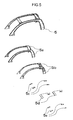
Fig. 5 is a schematic view of a vehicle body upper structural component. -
Fig. 6 is a layered example (schematic cross-sectional view) of a sandwiched member. -
Fig. 7 is a specific example (schematic cross-sectional view) of layering. -
Fig. 8 is a specific example (schematic cross-sectional view) of layering. -
- 1 Vehicle skeleton member
- 2 Underfloor structural component
- (2a, 2b, 2c: components)
- 3 Upperfloor structural component
- (3a, 3b, 3c, 3d, 3e, 3f, 3g: components)
- 4 Side sill structural component
- (4RH: right component, 4LH: left component, 4RHa, 4RHb, 4RHc, 4LHa, 4LHb, 4LHc: components)
- 5 Vehicle body upper structural component (pillar·roof)
- (5a, 5b, 5c, 5d, 5e: components)
- (a) Portion using sandwiched material AB
- (b) Portion using sandwiched material BC
- The following will explain embodiments of the present invention in sequence.
- The vehicle skeleton member of the invention is a vehicle skeleton member having a composite material of a thermoplastic resin and a carbon fiber, wherein the composite material is a unidirectional carbon-fiber composite material (A) that the form of the carbon fiber in the composite material is a continuous fibers aligned in one direction and/or a random carbon-fiber composite material (B) that the form of the carbon fiber in the composite material is a discontinuous fiber arranged two-dimensionally randomly.
- Here, the vehicle skeleton member of the invention is a member constituting the body of an automobile. Preferable specific examples include one or more selected from the group consisting of floor structural components, side sill structural components, dashboard structural components, vehicle body upper structural components including a pillar, a roof, a roof rail, and the like, and complexes thereof, for example, one having a vehicle upper shape (an upper vehicle body), one having a vehicle lower shape (lower vehicle body), one having a vehicle skeleton shape obtained by assembling the above structural components, and the like. Preferred floor body structural components include one or more double-deck type components for floor structure selected from the group consisting of underfloor structural components, upperfloor structural components, and the like.
- The vehicle skeleton member preferably contains one or more members having a composite material of a thermoplastic resin and a carbon fiber, and further contains a portion at which a plurality of the members having the composite material is joined. As methods for joining the members, known methods can be utilized, for examples, a method of using an adhesive agent, a method of mechanically fastening them with a bolt and a nut, and a method of joining them by heating and melting the thermoplastic resin that is a matrix component of the composite material. Of these, preferred is a method of joining them by heating and melting the thermoplastic resin that is a matrix component by vibration welding.
- The vehicle skeleton member of the invention may have a member having a material other than a composite material, such as a metal or a ceramic, a glass fiber composite material, a composite material in which a matrix component is a thermosetting resin, or the like within a range that does not impair the object of the invention, in addition to the member having the composite material of a thermoplastic resin and a reinforcing fiber. However, from the viewpoint of weight-saving of a vehicle body, it is preferable that the ratio of the member having the composite material in the vehicle skeleton member is high. Specifically, the weight ratio of the member having the composite material in the vehicle skeleton member is preferably 50% or more and more preferably 80% or more and 100% or less.
- The composite material constituting the vehicle skeleton member of the invention contains a thermoplastic resin and a carbon fiber. The weight ratio of the carbon fiber/thermoplastic resin in the composite material is preferably 20/80 to 80/20. More preferably, the ratio is 30/70 to 70/30. In either of the unidirectional carbon fiber composite material (A) and the random carbon fiber composite material (B) to be mentioned below, the carbon fiber contained therein preferably has an average fiber diameter of 3 to 12 µm.
- The form of the carbon fiber in the composite material is one in which a continuous fiber is aligned in one direction (A) and/or one in which a discontinuous fiber is two-dimensionally randomly arranged (B), which are described in the following in detail.
- The thermoplastic resin that is the matrix component of the composite material constituting the vehicle skeleton member of the invention includes polycarbonate resins, polyolefin resins, polyester resins, acrylic resins, polylactic acid, polyamide resins (aliphatic polyamide resins are also referred to as Nylon resins), ASA resins, ABS resins, polyether ketone resins, polyether imide resins, polyphenylene ether resins, polyphenylene oxide resins, polysulfone resins, polyether sulfone resins, polyether imide resins, polyether ether ketone resins, polyphenylene sulfide resins, polyamide imide resins, and compositions of two or more resins selected from these resins, but is not particularly limited. As the resin composition, preferred is at least one selected from the group consisting of compositions of polycarbonate resins and polyester resins, compositions of polycarbonate resins and ABS resins, compositions of polyphenylene ether resins and polyamide resins, compositions of polyamide resins and ABS resins, compositions of polyester resins and polyamide resins, and the like.
- In the case where the vehicle skeleton member is a component for a floor structure or a component for a side sill structure, the thermoplastic resin in the composite material is preferably an aliphatic polyamide resin, and specifically, Nylon 6, Nylon 66, or the like may be exemplified.
- In the case where the vehicle skeleton member is a component for a body upper structure, such as a pillar or a roof, a polyolefin may be also used as the thermoplastic resin in the composite material. As the polyolefin, one or more selected from the group consisting of polyethylene, polypropylene, and polystyrene may be preferably mentioned.
- The following will describe the unidirectional carbon-fiber composite material (A) (hereinafter sometimes abbreviated as "unidirectional material A") in which a continuous fiber is aligned in one direction. The unidirectional carbon-fiber composite material (A) is used singly, preferably as a layer body obtained by layering it with the other composite material as mentioned below, or more preferably as a sandwiched member.
- Here, the carbon fiber is a continuous fiber. In the invention, the continuous fiber refers to one having a fiber length of more than 100 mm. An upper limit of the fiber length of the continuous fiber is not specified but is sufficiently 15,000 mm or less in almost all vehicle skeleton members of the invention, is frequently sufficiently 5,000 mm or less, and is sufficiently 2,000 mm or less in quite a few cases. In the case of the continuous fiber, preferred is a sheet-shaped form of a woven or knitted fabric, a unidirectionally oriented sheet-shaped product of strands, a multi axial woven fabric, and the like, or a form of nonwoven fabric. In this regard, the multi axial woven fabric generally means a woven fabric in which one obtained by stacking a bundle of fiber-reinforced material aligned in one direction in a sheet form with changing the angle (multi axial woven fabric base material) is stitched with a stitching thread such as a Nylon thread, a polyester thread, or a glass fiber thread through the stacked body in a thickness direction between the front side and the reverse side of the stacked body along a surface direction, back and forth.
- In the unidirectional carbon-fiber composite material (A), fiber orientation can be arbitrarily selected depending on a stress state generated at the portion to be applied. Specifically, the fiber orientation is preferably made coincident with the main direction on which main stress acts. Moreover, it is also possible to use unidirectional carbon-fiber composite materials (A) having different fiber orientation depending on the stress state generated at the portion to be applied. In this case, the each angle formed by each unidirectional carbon-fiber composite material (A) in each layer is preferably from 30 to 150°, more preferably from 60 to 120°, and still more preferably from 80 to 100°. As the portion to be applied, the material can be preferably used to one or more selected from the group consisting of floor structural components, side sill structural components, vehicle body upper structural components, and the like.
- The following will describe the random carbon-fiber composite material (B) (hereinafter sometimes abbreviated as "random material B") in which a discontinuous fiber is two-dimensionally randomly arranged. The random carbon-fiber composite material (B) is used singly, preferably as a layer body obtained by layering it with the other composite material as mentioned below, or more preferably as a sandwiched member. The random carbon-fiber composite material (B) is preferably used singly at the portion where mechanical properties are required to be isotropic.
- The "two-dimensionally randomly (oriented)" means a state that a discontinuous carbon fiber is two-dimensionally entangled and deposited with forming a pseudo plane and each carbon fiber is oriented in the pseudo plane, as seen in a deposit obtained by cutting and opening a carbon fiber bundles, and spraying them. For a plate-shaped sample of the random carbon-fiber composite material in which a discontinuous fiber is two-dimensionally randomly arranged, tensile modulus in two directions crossing at a right angle each other in the plane is measured and a larger value of the obtained values of the tensile modulus is divided by a smaller value thereof and the resulting ratio becomes 2 or less.
- The discontinuous fiber constituting the random carbon-fiber composite material is specifically a short fiber having a fiber length of 0.1 to less than 10 mm or a long fiber having a fiber length of 10 mm to 100 mm. In the case of the discontinuous fiber, a form of a paper made using chopped strands or the like or a two-dimensional random mat is preferred. Of these, it is preferred to be a form of a random mat in which the carbon fiber includes a discontinuous carbon fiber having a fiber length of 10 to 100 mm and the carbon fiber is substantially orientated two-dimensionally randomly with fiber areal weight of 25 to 3,000 g/m2. Furthermore, preferred is a random mat in which a degree of fiber opening of the carbon fiber in the thermoplastic resin matrix is controlled and which contains the carbon fiber as a carbon fiber bundle having a specific number or more of carbon fibers and opened carbon fibers other than the bundle in a specific ratio.
- The random mat can be preferably obtained through the following steps:
- 1. a step of cutting the carbon fiber bundle (cutting step),
- 2. a step of introducing the cut carbon fiber in a tube and opening the fiber bundle by applying air to the fiber (fiber opening step),
- 3. a step of spraying the carbon fiber and a thermoplastic resin at the same time, simultaneously with diffusing the opened carbon fiber, while sucking the opened carbon fiber together with the thermoplastic resin in a particle-shape or a fiber-shape, and
- 4. a step of fixing the sprayed carbon fiber and thermoplastic resin (fixing step),
- The composite material in the vehicle skeleton member of the invention is the unidirectional carbon-fiber composite material (A) in which a continuous fiber is aligned in one direction and/or the form of the carbon fiber in the composite material is a random carbon-fiber composite material (B) in which a discontinuous fiber is two-dimensionally randomly arranged, but they are preferably used in a form of a layer body using them as a base layer. Namely, the invention includes a vehicle skeleton member having a layer body of the unidirectional carbon-fiber composite material (A) and/or a layer body of the random carbon-fiber composite material (B).
- Specific examples of the layer body of the unidirectional carbon-fiber composite material (A) include a layer body of a plurality of the unidirectional carbon-fiber composite materials (A), and a layer body of the unidirectional carbon-fiber composite material (A) and at least one layer selected from the group consisting of the random carbon-fiber composite material (B), a composite material (C) of an organic fiber and a thermoplastic resin (hereinafter sometimes referred to as "organic fiber thermoplastic resin composite material C"), a composite material of a glass fiber and a thermoplastic resin, and a neat thermoplastic resin layer.
- Of these, there may be preferably exemplified a sandwiched member having the unidirectional carbon-fiber composite material (A) as a skin layer and the random carbon-fiber composite material (B) as a core member (hereinafter sometimes referred to as sandwich AB) and a sandwich member having the unidirectional carbon-fiber composite material (A) as a skin layer and the composite material (C) of an organic fiber and a thermoplastic resin as a core member (hereinafter sometimes referred to as sandwich AC).
- Specific examples of the layer body of the random carbon-fiber composite material (B) include a layer body of a plurality of the random carbon-fiber composite materials (B), and a layer body of the random carbon-fiber composite material (B) and at least one layer selected from the group consisting of the unidirectional carbon-fiber composite material (A), the composite material (C) of an organic fiber and a thermoplastic resin, the composite material of a glass fiber and a thermoplastic resin, and the neat thermoplastic resin layer.
- Of these, there may be preferably exemplified a sandwiched material having the random carbon-fiber composite material (B) as a core member and the unidirectional carbon-fiber composite material (A) as a skin layer (the above sandwich AB) and a sandwich material having the random carbon-fiber composite material (B) as a skin layer and the composite material (C) of an organic fiber and a thermoplastic resin as a core member (hereinafter sometimes referred to as sandwich BC).
- A plurality of these layer bodies may be layered and layered examples of sandwiched materials are shown in
Fig. 6 . The angles in parentheses in the Figure are fiber directions of the unidirectional materials. It is also preferable to layer a plurality of the unidirectional carbon-fiber composite materials (A) and, in that case, they are preferably layered so as to result in plane symmetry.Fig. 7 andFig. 8 show specific examples in the case of overlapping. - As for the vehicle skeleton member, particularly preferred as a portion to which the layer body of the unidirectional carbon-fiber composite material (A) and the random carbon-fiber composite material (B), especially the sandwiched member having the unidirectional carbon-fiber composite material (A) as a skin layer and the random carbon-fiber composite material (B) as a core member is a particularly strength-requiring component which is arranged in a front and rear direction of a vehicle body and/or a right and left direction of the vehicle body among the vehicle skeleton members. Specifically, the vehicle skeleton member is a reinforcing structural part to be arranged at one or more selected from the group consisting of an underfloor structural component, an upperfloor structural component, a side sill structural component, a vehicle body upper structural component, and the like but can be used without particular limitation.
- As for the vehicle skeleton member, particularly preferred as a portion to which the layer body of the unidirectional carbon-fiber composite material (A) and the composite material (C) of an organic fiber and a thermoplastic resin, especially the sandwiched material having the unidirectional carbon-fiber composite material (A) as a skin layer and the composite material (C) of an organic fiber and a thermoplastic resin as a core member is a component for which performance of both of a reinforcing structure and an impact-absorbing structure is required among the vehicle skeleton members. Specifically, the vehicle skeleton member is one or more selected from the group consisting of an outer plate part of the underfloor structural component, a room-side reinforcing structural part of the upperfloor structural component, the side sill structural component, and a roof rail of the vehicle body upper structural component, and the like but can be used without particular limitation.
- As for the vehicle skeleton member, particularly preferred as a portion to which the layer body of the random carbon-fiber composite material (B) and the composite material (C) of an organic fiber and a thermoplastic resin, especially the sandwiched member having the random carbon-fiber composite material (B) as a skin layer and the composite material (C) of an organic fiber and a thermoplastic resin as a core member is a component having a complex shape, of which an impact-absorbing structure is required. Specifically, the vehicle skeleton member is one or more selected from the group consisting of a bulkhead part of the upperfloor structural component, a floor part, an outer plate part of the side sill structural component, an outer plate part of pillar of the vehicle body upper structural component, and the like but can be used without particular limitation.
- The following will describe the composite material (C) of an organic fiber and a thermoplastic resin to be used as a core member of the sandwiched material.
- The organic fiber includes one or more selected from the group consisting of para- or meta-aramide fibers, polyethylene terephthalate, polyethylene naphthalate, and the like. As the thermoplastic resin that is a matrix, the same ones as in the above carbon fiber composite material are used. The form of the organic fiber in the composite material includes woven fabrics, knitted goods, nonwoven fabrics, unidirectional materials, or random materials of discontinued fibers.
- Since the sandwiched material having the composite material (C) of the organic fiber and the thermoplastic resin as a core member can prevent parts from protruding to passengers upon impact or can absorb the impact, it is preferred to arrange the sandwiched material at a floor structural component, a side sill structural component, a place near to a living space among the vehicle body upper structural components such as pillar and roof, an outer plate part of the vehicle body structural component, and the like. In addition, the sandwiched material is preferably arranged at caps of a battery box.
- The composite materials constituting the vehicle skeleton member of the invention may contain non-carbon inorganic fibers such as glass fibers, boron fibers, or alumina fibers, fillers that are not fibrous, various additives such as an antioxidant unless they hinder the object of the invention, in addition to the aforementioned carbon fibers and organic fibers.
- Specific examples of the embodiment of the vehicle skeleton member of the invention will be explained with reference to
Fig. 1 to Fig. 8 . The components in the figures are constituted by the composite material of a thermoplastic resin and a carbon fiber but may contain member(s) having a material other than the composite material of a thermoplastic resin and a carbon fiber as mentioned above. Incidentally, with regard to the followingFigs. 1 to 8 , the average fiber diameter of the carbon fiber used is 7 µm unless otherwise stated. -
Fig. 1 is a schematic view of a structural component in the case where the vehicle skeleton member is a double-deck type one. A vehicle skeleton member 1 to be assembled by joining is manufactured from an underfloorstructural component 2, an upper floorstructural component 3, side sill structural components constituted by right one and left one 4RH, 4LH, and a vehicle body upper structural component 5 such as pillar and roof. -
Fig. 2 is a schematic view in the case where the vehicle skeleton member to be assembled by joining is the underfloor structural component. For obtaining the underfloorstructural component 2, it can be manufactured by first joining acomponent 2b and acomponent 2c and joining the thus obtained component to the lower side of 2a. The portion shown by -(a) in the figure uses a sandwiched material (thickness: 1.6 mm) having a unidirectional carbon-fiber composite material (A) as a skin layer (thickness: 0.3 mm, weight content of carbon fiber: 50% by weight, Nylon 6 resin is used) and a random carbon-fiber composite material (B) as a core member (thickness: 1.0 mm, carbon fiber length: 20 mm, weight content of carbon fiber: 40% by weight, Nylon 6 resin is used). The other portions contains a random carbon-fiber composite material (B) having Nylon 6 resin and having a carbon fiber length of 20 mm, a fiber weight content of 45% by weight, and a thickness of 1.6 mm singly. -
Fig. 3 is a schematic view in the case where the vehicle skeleton member to be assembled by joining is the upperfloor structural component. For obtaining the upperfloorstructural component 3, it can be manufactured by joining acomponent 3a, acomponent 3b, a component 3c, acomponent 3d, acomponent 3e, acomponent 3f, and acomponent 3g. The portion shown by -(a) in the figure uses a sandwiched material (thickness: 1.6 mm) having a unidirectional carbon-fiber composite material (A) as a skin layer (thickness: 0.3 mm, weight content of carbon fiber: 50% by weight, Nylon 6 resin is used) and a random carbon-fiber composite material (B) as a core member (thickness: 1.0 mm, carbon fiber length: 20 mm, weight content of carbon fiber: 40% by weight, Nylon 6 resin is used). The portion shown by -(b) in the figure uses a sandwiched material (thickness: 1.6 mm) having a random carbon-fiber composite material (B) as a skin layer (thickness: 0.5 mm, carbon fiber length: 20 mm, weight content of carbon fiber: 45% by weight, Nylon 6 resin is used) and a composite material (C) of an organic fiber and a thermoplastic resin as a core material (thickness: 0.6 mm, polyester plain weave fabric, weight content of polyester fiber: 50% by weight, Nylon 6 resin is used). The other portions contain a random carbon-fiber composite material (B) having Nylon 6 resin and having a carbon fiber length of 20 mm, a fiber weight content of 45% by weight, and a thickness of 1.6 mm singly. -
Fig. 4 is a schematic view in the case where the vehicle skeleton member to be assembled by joining is the side sill structural component. For obtaining side sill structural components including right one and left one 4RH and 4LH, 4RH is manufactured by joining a component 4RHa and components 4RHb and 4RHc and similarly 4LH is manufactured by joining a component 4LHa and components 4LHb and 4LHc. They contain a random carbon-fiber composite material (B) having Nylon 6 resin and having a carbon fiber length of 20 mm, a fiber weight content of 45% by weight, and a thickness of 1.6 mm singly. -
Fig. 5 is a schematic view in the case where the vehicle skeleton member to be assembled by joining is the vehicle body upper structural component such as pillar and roof. For obtaining the vehicle body upper structural component 5, it can be manufactured by joining acomponent 5a, acomponent 5b, acomponent 5c, acomponent 5d, and acomponent 5e. The portion shown by -(a) in the figure uses a sandwiched member (thickness: 1.6 mm) having a unidirectional carbon-fiber composite material (A) as a skin layer (thickness: 0.3 mm, weight content of carbon fiber: 50% by weight, polypropylene resin is used) and a random carbon-fiber composite material (B) as a core material (thickness: 1.0 mm, carbon fiber length: 20 mm, weight content of carbon fiber: 40% by weight, polypropylene resin is used). Portions other than thejoint component 5c and thecomponent 5e use a random carbon-fiber composite material (B) having polypropylene resin and having a carbon fiber length of 20 mm, a fiber weight content of 45% by weight, and a thickness of 1.6 mm singly. -
Fig. 6 is cross-sectional schematic views of layering examples of various sandwiched materials applicable to the vehicle skeleton member of the invention, which show:- a layering example in which the skin layer is a unidirectional carbon-fiber composite material (A) of 0° and the core layer is a random carbon-fiber composite material (B),
- a layering example in which the skin layer is unidirectional carbon-fiber composite materials (A) of +45°/-45° and the core layer is a random carbon-fiber composite material (B),
- a layering example in which the skin layer is a unidirectional carbon-fiber composite material (A) of 0° and the core layer is a composite material (C) of an organic fiber and a thermoplastic resin, and
- a layering example in which the skin layer is a random carbon-fiber composite material (B) and the core layer is a composite material (C) of an organic fiber and a thermoplastic resin, in this order from the top. Here, the angle such as "0°" in the case of "unidirectional carbon-fiber composite material (A) of 0°" is an angle of the carbon fiber (continuous fiber) in the unidirectional carbon-fiber composite material (A) to a standard direction determined for convenience in the design and handling of members constituted by the unidirectional carbon-fiber composite material (A) among the vehicle skeleton members of the invention, and is expressed by a numerical value in the range of larger than -90° to 90° or smaller.
-
Fig. 7 andFig. 8 are cross-sectional schematic views of specific examples of various layer structures applicable to cases where the vehicle skeleton member of the invention is constituted by the layer body. In this regard, in the case where the vehicle skeleton member of the invention is constituted by the layer body, and a layer of the unidirectional carbon-fiber composite material (A), a layer of the random carbon-fiber composite material (B), or a layer of the composite material (C) of an organic fiber and a thermoplastic resin is included plurally in the layer body, individual layers may be the completely same composite material or may be constituted by a plurality of kinds of layers different in composition, for example, a plurality of kinds of layers which meet the random carbon-fiber composite material (B) but are different in content of the carbon fiber or different in the thermoplastic resin that is a matrix component. - The vehicle skeleton member of the invention is suitable for formation of vehicle skeletons for automobiles and thus enables production of automobiles that are light in weight and also excellent in body strength.
Claims (10)
- A vehicle skeleton member comprising a composite material of a thermoplastic resin and a carbon fiber,
wherein the composite material is a unidirectional carbon-fiber composite material (A) that a form of the carbon fiber in the composite material is a continuous fiber aligned in one direction and/or a random carbon-fiber composite material (B) that a form of the carbon fiber in the composite material is a discontinuous fiber arranged two-dimensionally randomly. - The vehicle skeleton member according to claim 1,
wherein the vehicle skeleton member includes a layer body of the unidirectional carbon-fiber composite material (A) and the random carbon-fiber composite material (B). - The vehicle skeleton member according to claim 1,
wherein the vehicle skeleton member includes a layer body of the unidirectional carbon-fiber composite material (A) and a composite material (C) of an organic fiber and a thermoplastic resin. - The vehicle skeleton member according to claim 1,
wherein the vehicle skeleton member includes a layer body of the random carbon-fiber composite material (B) and a composite material (C) of an organic fiber and a thermoplastic resin. - The vehicle skeleton member according to any one of claims 1 to 4,
wherein the vehicle skeleton member is at least one selected from the group consisting of an underfloor structural component, an upperfloor structural component, a side sill structural component, and a vehicle body upper structural component. - The vehicle skeleton member according to claim 2,
wherein the vehicle skeleton member is at least one selected from the group consisting of a reinforcing structural part arranged on an underfloor structural component, an upperfloor structural component, a side sill structural component, and a vehicle body upper structural component. - The vehicle skeleton member according to claim 3,
wherein the vehicle skeleton member is at least one selected from the group consisting of an outer plate part of an underfloor structural component, a room-side reinforcing structural part of an upperfloor structural component, a side sill structural component, and a roof rail of a vehicle body upper structural component. - The vehicle skeleton member according to claim 4,
wherein the vehicle skeleton member is at least one selected from the group consisting of a bulkhead part of an upperfloor structural component, a floor part, an outer plate part of a side sill structural component, and an outer plate part of a pillar of a vehicle body upper structural component. - The vehicle skeleton member according to any one of claims 1 to 4,
wherein the vehicle skeleton member is an upperfloor structural component, an underfloor structural component, or a side sill structural component, and
the thermoplastic resin in the composite material is an aliphatic polyamide. - The vehicle skeleton member according to any one of claims 1 to 4,
wherein the vehicle skeleton member is a vehicle body upper structural component, and
the thermoplastic resin in the composite material is a polyolefin.
Applications Claiming Priority (2)
| Application Number | Priority Date | Filing Date | Title |
|---|---|---|---|
| JP2011021651 | 2011-02-03 | ||
| PCT/JP2012/052796 WO2012105716A1 (en) | 2011-02-03 | 2012-02-01 | Vehicle skeleton member |
Publications (3)
| Publication Number | Publication Date |
|---|---|
| EP2671779A1 true EP2671779A1 (en) | 2013-12-11 |
| EP2671779A4 EP2671779A4 (en) | 2014-04-09 |
| EP2671779B1 EP2671779B1 (en) | 2018-06-20 |
Family
ID=46602913
Family Applications (1)
| Application Number | Title | Priority Date | Filing Date |
|---|---|---|---|
| EP12742201.2A Active EP2671779B1 (en) | 2011-02-03 | 2012-02-01 | Vehicle skeleton member |
Country Status (6)
| Country | Link |
|---|---|
| US (1) | US8991900B2 (en) |
| EP (1) | EP2671779B1 (en) |
| JP (2) | JPWO2012105716A1 (en) |
| KR (1) | KR20140043318A (en) |
| CN (1) | CN103339023B (en) |
| WO (1) | WO2012105716A1 (en) |
Cited By (7)
| Publication number | Priority date | Publication date | Assignee | Title |
|---|---|---|---|---|
| CN105612101A (en) * | 2014-01-09 | 2016-05-25 | 宝马股份公司 | Component for a vehicle |
| EP3061663A1 (en) * | 2015-02-25 | 2016-08-31 | EDAG Engineering GmbH | Vehicle wall with reinforcement bulkhead |
| WO2018134762A1 (en) * | 2017-01-18 | 2018-07-26 | Sabic Global Technologies B.V. | Composite hybrid roof frame and methods to produce the same |
| WO2019034761A1 (en) * | 2017-08-18 | 2019-02-21 | Basf Se | Closed structural component and a process for preparing the same |
| IT201800003447A1 (en) * | 2018-03-12 | 2019-09-12 | Microtex Composites S R L | LAMINAR PRODUCT FOR STRUCTURAL USE OBTAINED FROM RECYCLED CARBON FIBER FELT AND PRODUCTION PROCESS |
| US11299214B2 (en) | 2017-08-18 | 2022-04-12 | Basf Se | Closed structural component and process for preparing the same |
| US20220212722A1 (en) * | 2019-04-15 | 2022-07-07 | Nissan Motor Co., Ltd. | Body side panel |
Families Citing this family (65)
| Publication number | Priority date | Publication date | Assignee | Title |
|---|---|---|---|---|
| KR20130140646A (en) * | 2010-09-06 | 2013-12-24 | 도레이 카부시키가이샤 | Structure for passenger vehicle interior, and manufacturing method therefor |
| EP2671780B1 (en) * | 2011-02-03 | 2015-09-09 | Teijin Limited | Vehicle skeleton member |
| WO2012105389A1 (en) * | 2011-02-03 | 2012-08-09 | 帝人株式会社 | Vehicle floor structure |
| DE102012102290A1 (en) * | 2012-03-19 | 2013-09-19 | Dr. Ing. H.C. F. Porsche Aktiengesellschaft | Fiber composite component of a motor vehicle, Monatageteil for such a fiber composite component and manufacturing process |
| DE102012010768A1 (en) * | 2012-05-31 | 2013-12-05 | Decoma (Germany) Gmbh | Structural component for a motor vehicle |
| DE102013006131A1 (en) * | 2013-04-10 | 2014-10-16 | Webasto SE | Roof frame component of a roof opening system of a vehicle |
| DE102013007805A1 (en) * | 2013-05-07 | 2014-11-13 | Daimler Ag | Pillar for a car body shell structure, method for the production of a pillar and motor vehicle bodyshell structure |
| DE102013209097A1 (en) | 2013-05-16 | 2014-11-20 | Bayerische Motoren Werke Aktiengesellschaft | Assembly in fiber composite construction for a motor vehicle |
| FR3008945B1 (en) * | 2013-07-25 | 2018-03-02 | Compagnie Plastic Omnium | SIDE AMOUNT FOR PERFECTED AUTOMOTIVE VEHICLE CASE |
| DE102013214782A1 (en) * | 2013-07-29 | 2015-01-29 | Bayerische Motoren Werke Aktiengesellschaft | Vehicle body with two glued body components |
| JP6035654B2 (en) * | 2013-09-18 | 2016-11-30 | 本田技研工業株式会社 | Auto body structure |
| JP5929871B2 (en) * | 2013-10-17 | 2016-06-08 | トヨタ自動車株式会社 | Method for molding thermoplastic resin material |
| US20160101543A1 (en) * | 2013-12-03 | 2016-04-14 | The Boeing Company | Hybrid Laminate and Molded Composite Structures |
| DE102014203330A1 (en) * | 2014-02-25 | 2015-08-27 | Bayerische Motoren Werke Aktiengesellschaft | Vehicle body with a side sill and a bottom plate |
| KR101611022B1 (en) | 2014-03-04 | 2016-04-11 | 현대자동차주식회사 | Upper-body frame system for vehicle |
| KR101575456B1 (en) * | 2014-03-04 | 2015-12-08 | 현대자동차주식회사 | Under-floor frame system for vehicle |
| KR101558745B1 (en) * | 2014-03-04 | 2015-10-07 | 현대자동차주식회사 | Under-floor frame system for vehicle |
| JP5855802B1 (en) * | 2014-03-18 | 2016-02-09 | 帝人株式会社 | Hollow structure and vehicle parts |
| DE102014004853A1 (en) * | 2014-04-03 | 2015-10-08 | Daimler Ag | Road vehicle with housing arrangement |
| US9592853B2 (en) | 2014-07-02 | 2017-03-14 | GM Global Technology Operations LLC | Corrugation designs |
| US9650003B2 (en) | 2014-07-02 | 2017-05-16 | GM Global Technology Operations LLC | Impact resistant component for a vehicle |
| US10160172B2 (en) | 2014-08-06 | 2018-12-25 | GM Global Technology Operations LLC | Mechanical interlocking realized through induction heating for polymeric composite repair |
| CN207141197U (en) * | 2014-08-12 | 2018-03-27 | 德韧营运有限责任公司 | Composite rear sill module |
| DE102014222933B4 (en) * | 2014-11-11 | 2021-09-09 | Bayerische Motoren Werke Aktiengesellschaft | Fiber composite component and method for producing a fiber composite component |
| KR101620226B1 (en) | 2014-12-01 | 2016-05-24 | 현대자동차주식회사 | B-pillar unit for vehicle |
| US9878489B2 (en) | 2014-12-18 | 2018-01-30 | GM Global Technology Operations LLC | Spin-welding of polymeric components having large surface area or non-complementary weld interfaces |
| JP6600942B2 (en) * | 2014-12-26 | 2019-11-06 | 三菱ケミカル株式会社 | Bonding structure of skeleton members for car bodies |
| CN104631828B (en) * | 2014-12-30 | 2017-07-07 | 中联重科股份有限公司 | Construction machinery cab main frame and manufacturing method, cab and construction machinery |
| DE102015204494B4 (en) * | 2015-03-12 | 2025-06-18 | Hyundai Motor Company | Hybrid side skirts for a motor vehicle and manufacturing method thereof |
| KR101693980B1 (en) * | 2015-04-28 | 2017-01-09 | 현대자동차주식회사 | Roof rack for vehicle using continuous fiber thermoplastic |
| KR101724926B1 (en) * | 2015-10-14 | 2017-04-18 | 현대자동차주식회사 | Rear floor arrangement for vehicle |
| US10695993B2 (en) | 2016-01-15 | 2020-06-30 | GM Global Technology Operations LLC | In-situ polymerization of polyamides for composite part repair |
| JP6402861B2 (en) | 2016-01-21 | 2018-10-10 | トヨタ自動車株式会社 | Vehicle suspension members |
| CN105857414A (en) * | 2016-04-26 | 2016-08-17 | 奇瑞汽车股份有限公司 | Connection structure for automobile parts and production method of connection structure |
| US10589477B2 (en) | 2016-05-02 | 2020-03-17 | GM Global Technology Operations LLC | Cosmetic repair of a thermoplastic carbon fiber composite |
| KR101806722B1 (en) | 2016-07-05 | 2017-12-08 | 현대자동차주식회사 | Shock absorber unit and manufacturing method of the same, connecting structure of member |
| DE102016116787B3 (en) * | 2016-09-07 | 2017-10-05 | Muhr Und Bender Kg | B-pillar for a motor vehicle body and motor vehicle body with such a B-pillar |
| KR101866080B1 (en) | 2016-10-31 | 2018-06-11 | 현대자동차주식회사 | Shock absorption structure of reinforce for center pillar |
| EP3538423B1 (en) * | 2016-11-09 | 2021-03-17 | Luvly AB | Chassis for a vehicle |
| DE102016222718A1 (en) * | 2016-11-18 | 2018-05-24 | Dr. Ing. H.C. F. Porsche Ag | Automotive body assembly |
| KR101884170B1 (en) * | 2016-11-18 | 2018-09-21 | 재단법인 한국탄소융합기술원 | Method for manufacturing carbon fiber reinforced plastic roof rail |
| CN106585727B (en) * | 2016-12-06 | 2018-10-16 | 北京新能源汽车股份有限公司 | Roof, automobile body that has it and vehicle |
| IT201600130313A1 (en) * | 2016-12-22 | 2018-06-22 | Automobili Lamborghini Spa | CARRYING STRUCTURE OF VEHICLE |
| US10611104B2 (en) | 2017-06-15 | 2020-04-07 | GM Global Technology Operations LLC | Heating elements for repair of molding defects for carbon fiber thermoplastic composites |
| CN109204495B (en) * | 2017-06-30 | 2020-11-06 | 比亚迪股份有限公司 | Vehicle body structure and vehicle |
| US11167802B2 (en) | 2017-07-04 | 2021-11-09 | Honda Motor Co., Ltd. | Vehicle pillar structure |
| JP7136633B2 (en) * | 2017-10-02 | 2022-09-13 | スズキ株式会社 | Plate-like member made of fiber-reinforced resin material |
| US10864946B2 (en) * | 2017-11-01 | 2020-12-15 | Mazda Motor Corporation | Automotive panel structure |
| JP6985953B2 (en) | 2018-02-13 | 2021-12-22 | 三菱重工業株式会社 | Method for manufacturing composite materials |
| US10583862B2 (en) | 2018-05-14 | 2020-03-10 | Ford Global Technologies, Llc | Vehicle roof bow |
| JP6968345B2 (en) * | 2018-05-24 | 2021-11-17 | 日産自動車株式会社 | Body side panel |
| DE102018113734A1 (en) * | 2018-06-08 | 2019-12-12 | Hymer Business Development Gmbh | Lightweight chassis |
| SG11202104513SA (en) * | 2018-11-01 | 2021-05-28 | Electric Vehicles Entpr Ltd | Chassis for an electric vehicle |
| US11753084B2 (en) * | 2019-01-18 | 2023-09-12 | Nissan Motor Co., Ltd. | Vehicle body structure |
| US11135903B2 (en) | 2019-10-17 | 2021-10-05 | Honda Motor Co., Ltd. | Method of assembling a composite side cabin structure with integrated structural core for a vehicle |
| US11472485B2 (en) | 2020-01-06 | 2022-10-18 | Workhorse Group Inc. | Land vehicles incorporating monocoques and modular mold systems for making the same |
| JP7655921B2 (en) * | 2020-01-06 | 2025-04-02 | ワークホース グループ, インク. | Method for producing monocoque structures for land vehicles using modular systems |
| EP3873793A4 (en) | 2020-01-06 | 2023-06-14 | Workhorse Group Inc. | LAND VEHICLES INCORPORATING DETACHABLE POWERTRAIN UNITS, POWERTRAIN UNITS AND ASSOCIATED METHODS |
| CN115485185A (en) * | 2020-01-06 | 2022-12-16 | 沃尔克霍尔塞集团公司 | Land vehicle comprising a monocoque structure and modular mould system for manufacturing the same |
| JP7196126B2 (en) * | 2020-03-18 | 2022-12-26 | 株式会社有沢製作所 | Connecting member for vehicle structure |
| CN111516761B (en) * | 2020-04-20 | 2022-10-11 | 重庆长安汽车股份有限公司 | Carbon fiber composite material automobile front floor, manufacturing method and automobile |
| FR3118619B1 (en) * | 2021-01-05 | 2023-12-15 | Yanara Tech | Vehicle passenger cell |
| EP4166425A1 (en) | 2021-10-15 | 2023-04-19 | Luvly AB | Chassis for a vehicle and method for forming a chassis for a vehicle |
| EP4166426A1 (en) | 2021-10-15 | 2023-04-19 | Luvly AB | Sandwich plate element connection system and method for connecting sandwich plate elements |
| JP2025101954A (en) * | 2023-12-26 | 2025-07-08 | 矢崎総業株式会社 | Wire harness assembly and manufacturing method thereof |
Citations (4)
| Publication number | Priority date | Publication date | Assignee | Title |
|---|---|---|---|---|
| JPS63232083A (en) | 1987-03-20 | 1988-09-28 | Honda Motor Co Ltd | Automobile floor structure |
| JPH0310973U (en) | 1989-06-20 | 1991-02-01 | ||
| WO2010013645A1 (en) | 2008-07-31 | 2010-02-04 | 東レ株式会社 | Prepreg, preform, molded product, and method for manufacturing prepreg |
| JP2010235779A (en) | 2009-03-31 | 2010-10-21 | Toray Ind Inc | Prepregs, preforms and molded products |
Family Cites Families (28)
| Publication number | Priority date | Publication date | Assignee | Title |
|---|---|---|---|---|
| CN85200688U (en) * | 1985-04-01 | 1986-09-17 | 唐锦生 | Full monocoque car body made of composite |
| JPH07103244B2 (en) * | 1987-09-24 | 1995-11-08 | 株式会社クラレ | Stamping molding material |
| JPH089200B2 (en) | 1989-04-27 | 1996-01-31 | 日本鋼管株式会社 | Fiber-reinforced plastic sheet and manufacturing method thereof |
| JPH09309171A (en) * | 1996-05-22 | 1997-12-02 | Nitto Boseki Co Ltd | Fiber-reinforced composite material and safety shoe toecap made therefrom |
| JP2000038157A (en) * | 1998-07-21 | 2000-02-08 | Mazda Motor Corp | Body reinforcement structure and method of forming the same |
| JP3968895B2 (en) * | 1998-09-30 | 2007-08-29 | 東レ株式会社 | Method for manufacturing FRP structure |
| DE10080607D2 (en) * | 1999-03-15 | 2002-04-11 | Brose Fahrzeugteile | Automotive seat |
| JP2001010542A (en) * | 1999-07-01 | 2001-01-16 | Idemitsu Petrochem Co Ltd | Automotive floor and manufacturing method thereof |
| US6206458B1 (en) * | 1999-09-13 | 2001-03-27 | Daimlerchrysler Corporation | Vehicle body structure |
| DE50004943D1 (en) * | 1999-10-20 | 2004-02-05 | Rcc Regional Compact Car Ag Ku | VEHICLE CELL MADE OF FIBER REINFORCED THERMOPLASTIC PLASTIC |
| EP1384570A4 (en) * | 2001-08-28 | 2009-04-29 | Toray Industries | Cfrp plate material and method for preparation thereof |
| DE10351181A1 (en) * | 2003-11-03 | 2005-06-02 | Dr.Ing.H.C. F. Porsche Ag | Wall for a construction of a motor vehicle |
| ATE549230T1 (en) * | 2004-01-23 | 2012-03-15 | Toray Industries | FIBER REINFORCED PANEL FOR MOTOR VEHICLE |
| JP4645334B2 (en) * | 2004-07-14 | 2011-03-09 | 東レ株式会社 | Fiber reinforced plastic parts |
| US7281754B2 (en) * | 2005-01-24 | 2007-10-16 | Behr Eugene E | Flexible panel system |
| MX2007013800A (en) * | 2005-05-04 | 2008-04-04 | Groep Stevens Int Nv | Support panel structure. |
| TWI414543B (en) * | 2006-02-24 | 2013-11-11 | Toray Industries | Fiber reinforced thermoplastic resin molded body, molding material, and process for manufacturing the same |
| JP4988229B2 (en) * | 2006-03-25 | 2012-08-01 | 帝人テクノプロダクツ株式会社 | A hybrid composite material excellent in surface smoothness and a molding method thereof. |
| JP4784425B2 (en) * | 2006-07-28 | 2011-10-05 | トヨタ自動車株式会社 | Lower body structure and manufacturing method thereof |
| JP4784435B2 (en) * | 2006-08-08 | 2011-10-05 | トヨタ自動車株式会社 | Integrated fiber reinforced plastic member for car body |
| JP4788539B2 (en) | 2006-09-13 | 2011-10-05 | トヨタ自動車株式会社 | Body panel structure |
| JP2008114633A (en) * | 2006-11-01 | 2008-05-22 | Honda Motor Co Ltd | Roof pillar integral molded member and roof pillar garnish integral molded member |
| JP5010447B2 (en) * | 2007-12-04 | 2012-08-29 | トヨタ自動車株式会社 | Manufacturing method of fiber reinforced resin member |
| US7784856B2 (en) * | 2008-01-11 | 2010-08-31 | United States Council For Automotive Research | Dynamic load bearing composite floor pan for an automotive vehicle |
| JP2010137639A (en) * | 2008-12-10 | 2010-06-24 | Teijin Ltd | Floor pan for automobile formed of carbon fiber composite |
| JP5384094B2 (en) * | 2008-12-29 | 2014-01-08 | トヨタ自動車株式会社 | Structure and resin transfer molding molding method |
| US8905464B2 (en) * | 2009-10-29 | 2014-12-09 | Metalsa Automotive Gmbh | Vehicle part with structural reinforcement part |
| WO2012105389A1 (en) * | 2011-02-03 | 2012-08-09 | 帝人株式会社 | Vehicle floor structure |
-
2012
- 2012-02-01 WO PCT/JP2012/052796 patent/WO2012105716A1/en not_active Ceased
- 2012-02-01 JP JP2012556005A patent/JPWO2012105716A1/en active Pending
- 2012-02-01 EP EP12742201.2A patent/EP2671779B1/en active Active
- 2012-02-01 CN CN201280007773.1A patent/CN103339023B/en active Active
- 2012-02-01 KR KR1020137020556A patent/KR20140043318A/en not_active Ceased
-
2013
- 2013-08-02 US US13/957,465 patent/US8991900B2/en active Active
-
2015
- 2015-08-31 JP JP2015170845A patent/JP2016005955A/en active Pending
Patent Citations (5)
| Publication number | Priority date | Publication date | Assignee | Title |
|---|---|---|---|---|
| JPS63232083A (en) | 1987-03-20 | 1988-09-28 | Honda Motor Co Ltd | Automobile floor structure |
| JPH0310973U (en) | 1989-06-20 | 1991-02-01 | ||
| WO2010013645A1 (en) | 2008-07-31 | 2010-02-04 | 東レ株式会社 | Prepreg, preform, molded product, and method for manufacturing prepreg |
| EP2314642A1 (en) | 2008-07-31 | 2011-04-27 | Toray Industries, Inc. | Prepreg, preform, molded product, and method for manufacturing prepreg |
| JP2010235779A (en) | 2009-03-31 | 2010-10-21 | Toray Ind Inc | Prepregs, preforms and molded products |
Non-Patent Citations (1)
| Title |
|---|
| See also references of WO2012105716A1 |
Cited By (13)
| Publication number | Priority date | Publication date | Assignee | Title |
|---|---|---|---|---|
| CN105612101B (en) * | 2014-01-09 | 2017-11-07 | 宝马股份公司 | Component and its manufacture method for vehicle |
| US10336383B2 (en) | 2014-01-09 | 2019-07-02 | Bayerische Motoren Werke Aktiengesellschaft | Component for a vehicle |
| CN105612101A (en) * | 2014-01-09 | 2016-05-25 | 宝马股份公司 | Component for a vehicle |
| EP3061663A1 (en) * | 2015-02-25 | 2016-08-31 | EDAG Engineering GmbH | Vehicle wall with reinforcement bulkhead |
| US11040602B2 (en) | 2017-01-18 | 2021-06-22 | Sabic Global Technologies B.V. | Composite hybrid roof frame and methods to produce the same |
| WO2018134762A1 (en) * | 2017-01-18 | 2018-07-26 | Sabic Global Technologies B.V. | Composite hybrid roof frame and methods to produce the same |
| CN110325388B (en) * | 2017-01-18 | 2023-01-31 | 沙特基础工业全球技术公司 | Composite hybrid top frame and method of making same |
| CN110325388A (en) * | 2017-01-18 | 2019-10-11 | 沙特基础工业全球技术公司 | Compound hybrid top frame and its manufacturing method |
| US11299214B2 (en) | 2017-08-18 | 2022-04-12 | Basf Se | Closed structural component and process for preparing the same |
| WO2019034761A1 (en) * | 2017-08-18 | 2019-02-21 | Basf Se | Closed structural component and a process for preparing the same |
| IT201800003447A1 (en) * | 2018-03-12 | 2019-09-12 | Microtex Composites S R L | LAMINAR PRODUCT FOR STRUCTURAL USE OBTAINED FROM RECYCLED CARBON FIBER FELT AND PRODUCTION PROCESS |
| US20220212722A1 (en) * | 2019-04-15 | 2022-07-07 | Nissan Motor Co., Ltd. | Body side panel |
| US11814105B2 (en) * | 2019-04-15 | 2023-11-14 | Nissan Motor Co., Ltd. | Body side panel |
Also Published As
| Publication number | Publication date |
|---|---|
| US8991900B2 (en) | 2015-03-31 |
| CN103339023B (en) | 2016-03-02 |
| US20130313862A1 (en) | 2013-11-28 |
| EP2671779A4 (en) | 2014-04-09 |
| EP2671779B1 (en) | 2018-06-20 |
| JPWO2012105716A1 (en) | 2014-07-03 |
| WO2012105716A1 (en) | 2012-08-09 |
| CN103339023A (en) | 2013-10-02 |
| JP2016005955A (en) | 2016-01-14 |
| KR20140043318A (en) | 2014-04-09 |
Similar Documents
| Publication | Publication Date | Title |
|---|---|---|
| EP2671779B1 (en) | Vehicle skeleton member | |
| US8814255B2 (en) | Vehicle floor structure | |
| EP2671780B1 (en) | Vehicle skeleton member | |
| KR101315741B1 (en) | Battery Pack Case Assembly for Electric Vehicles Using Plastic Composite and method for manufacturing the same | |
| EP2669081B1 (en) | Joint body of carbon fiber reinforced composite material | |
| US10052851B2 (en) | Fiber reinforced plastic member for vehicle and method of producing the same | |
| EP3863910B1 (en) | Safety cabin for a recreational or camper van with deformation elements, and manufacturing method for such a safety cabin | |
| EP3549741A1 (en) | Fiber-reinforced resin molded article and method for manufacturing fiber-reinforced resin molded article | |
| KR20150103438A (en) | front end module carrier using continuous fiber reinforced thermoplastics and method of manufacturing | |
| US20070259135A1 (en) | Textile Core Sandwich Structures | |
| JP2015178241A (en) | Method of producing fiber-reinforced resin material | |
| JP2012035442A (en) | Fiber-reinforced resin member, and fastening structure | |
| DE202020105789U1 (en) | Safety cabin for a mobile home or motorhome with highly stable walls, which preferably comprise natural fibers | |
| KR20150026168A (en) | Impact beam for car door | |
| JP2011251444A (en) | Continuous fiber composite material structure, method for manufacturing the same, and composite molded object using the continuous fiber composite material structure | |
| JP2005314837A (en) | Multi-axis fabric, preform material, and fiber reinforced plastic molding | |
| JP2014098096A (en) | Structural body |
Legal Events
| Date | Code | Title | Description |
|---|---|---|---|
| PUAI | Public reference made under article 153(3) epc to a published international application that has entered the european phase |
Free format text: ORIGINAL CODE: 0009012 |
|
| 17P | Request for examination filed |
Effective date: 20130903 |
|
| AK | Designated contracting states |
Kind code of ref document: A1 Designated state(s): AL AT BE BG CH CY CZ DE DK EE ES FI FR GB GR HR HU IE IS IT LI LT LU LV MC MK MT NL NO PL PT RO RS SE SI SK SM TR |
|
| A4 | Supplementary search report drawn up and despatched |
Effective date: 20140306 |
|
| RIC1 | Information provided on ipc code assigned before grant |
Ipc: B62D 25/06 20060101ALI20140228BHEP Ipc: B62D 29/04 20060101AFI20140228BHEP Ipc: B62D 25/20 20060101ALI20140228BHEP Ipc: B62D 25/04 20060101ALI20140228BHEP |
|
| 17Q | First examination report despatched |
Effective date: 20140319 |
|
| DAX | Request for extension of the european patent (deleted) | ||
| TPAC | Observations filed by third parties |
Free format text: ORIGINAL CODE: EPIDOSNTIPA |
|
| TPAC | Observations filed by third parties |
Free format text: ORIGINAL CODE: EPIDOSNTIPA |
|
| STAA | Information on the status of an ep patent application or granted ep patent |
Free format text: STATUS: EXAMINATION IS IN PROGRESS |
|
| GRAP | Despatch of communication of intention to grant a patent |
Free format text: ORIGINAL CODE: EPIDOSNIGR1 |
|
| STAA | Information on the status of an ep patent application or granted ep patent |
Free format text: STATUS: GRANT OF PATENT IS INTENDED |
|
| INTG | Intention to grant announced |
Effective date: 20171215 |
|
| GRAS | Grant fee paid |
Free format text: ORIGINAL CODE: EPIDOSNIGR3 |
|
| GRAJ | Information related to disapproval of communication of intention to grant by the applicant or resumption of examination proceedings by the epo deleted |
Free format text: ORIGINAL CODE: EPIDOSDIGR1 |
|
| GRAL | Information related to payment of fee for publishing/printing deleted |
Free format text: ORIGINAL CODE: EPIDOSDIGR3 |
|
| STAA | Information on the status of an ep patent application or granted ep patent |
Free format text: STATUS: EXAMINATION IS IN PROGRESS |
|
| GRAR | Information related to intention to grant a patent recorded |
Free format text: ORIGINAL CODE: EPIDOSNIGR71 |
|
| STAA | Information on the status of an ep patent application or granted ep patent |
Free format text: STATUS: GRANT OF PATENT IS INTENDED |
|
| GRAA | (expected) grant |
Free format text: ORIGINAL CODE: 0009210 |
|
| STAA | Information on the status of an ep patent application or granted ep patent |
Free format text: STATUS: THE PATENT HAS BEEN GRANTED |
|
| INTC | Intention to grant announced (deleted) | ||
| AK | Designated contracting states |
Kind code of ref document: B1 Designated state(s): AL AT BE BG CH CY CZ DE DK EE ES FI FR GB GR HR HU IE IS IT LI LT LU LV MC MK MT NL NO PL PT RO RS SE SI SK SM TR |
|
| INTG | Intention to grant announced |
Effective date: 20180514 |
|
| REG | Reference to a national code |
Ref country code: GB Ref legal event code: FG4D |
|
| REG | Reference to a national code |
Ref country code: IE Ref legal event code: FG4D |
|
| REG | Reference to a national code |
Ref country code: AT Ref legal event code: REF Ref document number: 1010384 Country of ref document: AT Kind code of ref document: T Effective date: 20180715 |
|
| REG | Reference to a national code |
Ref country code: DE Ref legal event code: R096 Ref document number: 602012047650 Country of ref document: DE |
|
| REG | Reference to a national code |
Ref country code: NL Ref legal event code: MP Effective date: 20180620 |
|
| PG25 | Lapsed in a contracting state [announced via postgrant information from national office to epo] |
Ref country code: SE Free format text: LAPSE BECAUSE OF FAILURE TO SUBMIT A TRANSLATION OF THE DESCRIPTION OR TO PAY THE FEE WITHIN THE PRESCRIBED TIME-LIMIT Effective date: 20180620 Ref country code: LT Free format text: LAPSE BECAUSE OF FAILURE TO SUBMIT A TRANSLATION OF THE DESCRIPTION OR TO PAY THE FEE WITHIN THE PRESCRIBED TIME-LIMIT Effective date: 20180620 Ref country code: BG Free format text: LAPSE BECAUSE OF FAILURE TO SUBMIT A TRANSLATION OF THE DESCRIPTION OR TO PAY THE FEE WITHIN THE PRESCRIBED TIME-LIMIT Effective date: 20180920 Ref country code: FI Free format text: LAPSE BECAUSE OF FAILURE TO SUBMIT A TRANSLATION OF THE DESCRIPTION OR TO PAY THE FEE WITHIN THE PRESCRIBED TIME-LIMIT Effective date: 20180620 Ref country code: NO Free format text: LAPSE BECAUSE OF FAILURE TO SUBMIT A TRANSLATION OF THE DESCRIPTION OR TO PAY THE FEE WITHIN THE PRESCRIBED TIME-LIMIT Effective date: 20180920 |
|
| REG | Reference to a national code |
Ref country code: LT Ref legal event code: MG4D |
|
| PG25 | Lapsed in a contracting state [announced via postgrant information from national office to epo] |
Ref country code: RS Free format text: LAPSE BECAUSE OF FAILURE TO SUBMIT A TRANSLATION OF THE DESCRIPTION OR TO PAY THE FEE WITHIN THE PRESCRIBED TIME-LIMIT Effective date: 20180620 Ref country code: LV Free format text: LAPSE BECAUSE OF FAILURE TO SUBMIT A TRANSLATION OF THE DESCRIPTION OR TO PAY THE FEE WITHIN THE PRESCRIBED TIME-LIMIT Effective date: 20180620 Ref country code: HR Free format text: LAPSE BECAUSE OF FAILURE TO SUBMIT A TRANSLATION OF THE DESCRIPTION OR TO PAY THE FEE WITHIN THE PRESCRIBED TIME-LIMIT Effective date: 20180620 Ref country code: GR Free format text: LAPSE BECAUSE OF FAILURE TO SUBMIT A TRANSLATION OF THE DESCRIPTION OR TO PAY THE FEE WITHIN THE PRESCRIBED TIME-LIMIT Effective date: 20180921 |
|
| REG | Reference to a national code |
Ref country code: AT Ref legal event code: MK05 Ref document number: 1010384 Country of ref document: AT Kind code of ref document: T Effective date: 20180620 |
|
| PG25 | Lapsed in a contracting state [announced via postgrant information from national office to epo] |
Ref country code: NL Free format text: LAPSE BECAUSE OF FAILURE TO SUBMIT A TRANSLATION OF THE DESCRIPTION OR TO PAY THE FEE WITHIN THE PRESCRIBED TIME-LIMIT Effective date: 20180620 |
|
| PG25 | Lapsed in a contracting state [announced via postgrant information from national office to epo] |
Ref country code: SK Free format text: LAPSE BECAUSE OF FAILURE TO SUBMIT A TRANSLATION OF THE DESCRIPTION OR TO PAY THE FEE WITHIN THE PRESCRIBED TIME-LIMIT Effective date: 20180620 Ref country code: IS Free format text: LAPSE BECAUSE OF FAILURE TO SUBMIT A TRANSLATION OF THE DESCRIPTION OR TO PAY THE FEE WITHIN THE PRESCRIBED TIME-LIMIT Effective date: 20181020 Ref country code: PL Free format text: LAPSE BECAUSE OF FAILURE TO SUBMIT A TRANSLATION OF THE DESCRIPTION OR TO PAY THE FEE WITHIN THE PRESCRIBED TIME-LIMIT Effective date: 20180620 Ref country code: AT Free format text: LAPSE BECAUSE OF FAILURE TO SUBMIT A TRANSLATION OF THE DESCRIPTION OR TO PAY THE FEE WITHIN THE PRESCRIBED TIME-LIMIT Effective date: 20180620 Ref country code: EE Free format text: LAPSE BECAUSE OF FAILURE TO SUBMIT A TRANSLATION OF THE DESCRIPTION OR TO PAY THE FEE WITHIN THE PRESCRIBED TIME-LIMIT Effective date: 20180620 Ref country code: RO Free format text: LAPSE BECAUSE OF FAILURE TO SUBMIT A TRANSLATION OF THE DESCRIPTION OR TO PAY THE FEE WITHIN THE PRESCRIBED TIME-LIMIT Effective date: 20180620 Ref country code: CZ Free format text: LAPSE BECAUSE OF FAILURE TO SUBMIT A TRANSLATION OF THE DESCRIPTION OR TO PAY THE FEE WITHIN THE PRESCRIBED TIME-LIMIT Effective date: 20180620 |
|
| PG25 | Lapsed in a contracting state [announced via postgrant information from national office to epo] |
Ref country code: ES Free format text: LAPSE BECAUSE OF FAILURE TO SUBMIT A TRANSLATION OF THE DESCRIPTION OR TO PAY THE FEE WITHIN THE PRESCRIBED TIME-LIMIT Effective date: 20180620 Ref country code: SM Free format text: LAPSE BECAUSE OF FAILURE TO SUBMIT A TRANSLATION OF THE DESCRIPTION OR TO PAY THE FEE WITHIN THE PRESCRIBED TIME-LIMIT Effective date: 20180620 Ref country code: IT Free format text: LAPSE BECAUSE OF FAILURE TO SUBMIT A TRANSLATION OF THE DESCRIPTION OR TO PAY THE FEE WITHIN THE PRESCRIBED TIME-LIMIT Effective date: 20180620 |
|
| REG | Reference to a national code |
Ref country code: DE Ref legal event code: R097 Ref document number: 602012047650 Country of ref document: DE |
|
| PLBE | No opposition filed within time limit |
Free format text: ORIGINAL CODE: 0009261 |
|
| STAA | Information on the status of an ep patent application or granted ep patent |
Free format text: STATUS: NO OPPOSITION FILED WITHIN TIME LIMIT |
|
| 26N | No opposition filed |
Effective date: 20190321 |
|
| PG25 | Lapsed in a contracting state [announced via postgrant information from national office to epo] |
Ref country code: DK Free format text: LAPSE BECAUSE OF FAILURE TO SUBMIT A TRANSLATION OF THE DESCRIPTION OR TO PAY THE FEE WITHIN THE PRESCRIBED TIME-LIMIT Effective date: 20180620 |
|
| PG25 | Lapsed in a contracting state [announced via postgrant information from national office to epo] |
Ref country code: SI Free format text: LAPSE BECAUSE OF FAILURE TO SUBMIT A TRANSLATION OF THE DESCRIPTION OR TO PAY THE FEE WITHIN THE PRESCRIBED TIME-LIMIT Effective date: 20180620 |
|
| REG | Reference to a national code |
Ref country code: CH Ref legal event code: PL |
|
| PG25 | Lapsed in a contracting state [announced via postgrant information from national office to epo] |
Ref country code: LU Free format text: LAPSE BECAUSE OF NON-PAYMENT OF DUE FEES Effective date: 20190201 Ref country code: MC Free format text: LAPSE BECAUSE OF FAILURE TO SUBMIT A TRANSLATION OF THE DESCRIPTION OR TO PAY THE FEE WITHIN THE PRESCRIBED TIME-LIMIT Effective date: 20180620 |
|
| REG | Reference to a national code |
Ref country code: BE Ref legal event code: MM Effective date: 20190228 |
|
| REG | Reference to a national code |
Ref country code: IE Ref legal event code: MM4A |
|
| PG25 | Lapsed in a contracting state [announced via postgrant information from national office to epo] |
Ref country code: AL Free format text: LAPSE BECAUSE OF FAILURE TO SUBMIT A TRANSLATION OF THE DESCRIPTION OR TO PAY THE FEE WITHIN THE PRESCRIBED TIME-LIMIT Effective date: 20180620 |
|
| PG25 | Lapsed in a contracting state [announced via postgrant information from national office to epo] |
Ref country code: CH Free format text: LAPSE BECAUSE OF NON-PAYMENT OF DUE FEES Effective date: 20190228 Ref country code: LI Free format text: LAPSE BECAUSE OF NON-PAYMENT OF DUE FEES Effective date: 20190228 |
|
| PG25 | Lapsed in a contracting state [announced via postgrant information from national office to epo] |
Ref country code: IE Free format text: LAPSE BECAUSE OF NON-PAYMENT OF DUE FEES Effective date: 20190201 |
|
| PG25 | Lapsed in a contracting state [announced via postgrant information from national office to epo] |
Ref country code: BE Free format text: LAPSE BECAUSE OF NON-PAYMENT OF DUE FEES Effective date: 20190228 |
|
| PG25 | Lapsed in a contracting state [announced via postgrant information from national office to epo] |
Ref country code: TR Free format text: LAPSE BECAUSE OF FAILURE TO SUBMIT A TRANSLATION OF THE DESCRIPTION OR TO PAY THE FEE WITHIN THE PRESCRIBED TIME-LIMIT Effective date: 20180620 |
|
| PG25 | Lapsed in a contracting state [announced via postgrant information from national office to epo] |
Ref country code: MT Free format text: LAPSE BECAUSE OF NON-PAYMENT OF DUE FEES Effective date: 20190201 Ref country code: PT Free format text: LAPSE BECAUSE OF FAILURE TO SUBMIT A TRANSLATION OF THE DESCRIPTION OR TO PAY THE FEE WITHIN THE PRESCRIBED TIME-LIMIT Effective date: 20181022 |
|
| PG25 | Lapsed in a contracting state [announced via postgrant information from national office to epo] |
Ref country code: CY Free format text: LAPSE BECAUSE OF FAILURE TO SUBMIT A TRANSLATION OF THE DESCRIPTION OR TO PAY THE FEE WITHIN THE PRESCRIBED TIME-LIMIT Effective date: 20180620 |
|
| PG25 | Lapsed in a contracting state [announced via postgrant information from national office to epo] |
Ref country code: HU Free format text: LAPSE BECAUSE OF FAILURE TO SUBMIT A TRANSLATION OF THE DESCRIPTION OR TO PAY THE FEE WITHIN THE PRESCRIBED TIME-LIMIT; INVALID AB INITIO Effective date: 20120201 |
|
| PGFP | Annual fee paid to national office [announced via postgrant information from national office to epo] |
Ref country code: GB Payment date: 20220223 Year of fee payment: 11 |
|
| PGFP | Annual fee paid to national office [announced via postgrant information from national office to epo] |
Ref country code: FR Payment date: 20220216 Year of fee payment: 11 |
|
| PG25 | Lapsed in a contracting state [announced via postgrant information from national office to epo] |
Ref country code: MK Free format text: LAPSE BECAUSE OF FAILURE TO SUBMIT A TRANSLATION OF THE DESCRIPTION OR TO PAY THE FEE WITHIN THE PRESCRIBED TIME-LIMIT Effective date: 20180620 |
|
| REG | Reference to a national code |
Ref country code: DE Ref legal event code: R084 Ref document number: 602012047650 Country of ref document: DE |
|
| GBPC | Gb: european patent ceased through non-payment of renewal fee |
Effective date: 20230201 |
|
| PG25 | Lapsed in a contracting state [announced via postgrant information from national office to epo] |
Ref country code: GB Free format text: LAPSE BECAUSE OF NON-PAYMENT OF DUE FEES Effective date: 20230201 |
|
| PG25 | Lapsed in a contracting state [announced via postgrant information from national office to epo] |
Ref country code: GB Free format text: LAPSE BECAUSE OF NON-PAYMENT OF DUE FEES Effective date: 20230201 Ref country code: FR Free format text: LAPSE BECAUSE OF NON-PAYMENT OF DUE FEES Effective date: 20230228 |
|
| PGFP | Annual fee paid to national office [announced via postgrant information from national office to epo] |
Ref country code: DE Payment date: 20260218 Year of fee payment: 15 |