EP2671426B1 - Vorrichtung zur regulierung der elektrode eines elektro-reduktionsofens - Google Patents
Vorrichtung zur regulierung der elektrode eines elektro-reduktionsofens Download PDFInfo
- Publication number
- EP2671426B1 EP2671426B1 EP12703046.8A EP12703046A EP2671426B1 EP 2671426 B1 EP2671426 B1 EP 2671426B1 EP 12703046 A EP12703046 A EP 12703046A EP 2671426 B1 EP2671426 B1 EP 2671426B1
- Authority
- EP
- European Patent Office
- Prior art keywords
- electrode
- counterweight
- metres
- reduction furnace
- support cable
- Prior art date
- Legal status (The legal status is an assumption and is not a legal conclusion. Google has not performed a legal analysis and makes no representation as to the accuracy of the status listed.)
- Not-in-force
Links
- 230000009467 reduction Effects 0.000 title claims description 13
- 238000010891 electric arc Methods 0.000 title 1
- 238000010168 coupling process Methods 0.000 claims description 8
- 238000005859 coupling reaction Methods 0.000 claims description 8
- 230000008878 coupling Effects 0.000 claims description 6
- 239000007788 liquid Substances 0.000 claims description 5
- OKTJSMMVPCPJKN-UHFFFAOYSA-N Carbon Chemical compound [C] OKTJSMMVPCPJKN-UHFFFAOYSA-N 0.000 claims description 3
- 239000000463 material Substances 0.000 claims description 3
- 230000001105 regulatory effect Effects 0.000 claims description 3
- 239000007787 solid Substances 0.000 claims description 3
- 229910052799 carbon Inorganic materials 0.000 claims description 2
- 230000009969 flowable effect Effects 0.000 claims description 2
- 238000005303 weighing Methods 0.000 claims 1
- XLYOFNOQVPJJNP-UHFFFAOYSA-N water Substances O XLYOFNOQVPJJNP-UHFFFAOYSA-N 0.000 description 6
- 239000002893 slag Substances 0.000 description 5
- 230000008859 change Effects 0.000 description 4
- 239000002184 metal Substances 0.000 description 4
- 229910052751 metal Inorganic materials 0.000 description 4
- 229910000831 Steel Inorganic materials 0.000 description 2
- 239000000155 melt Substances 0.000 description 2
- 239000010959 steel Substances 0.000 description 2
- 239000000725 suspension Substances 0.000 description 2
- 229910000604 Ferrochrome Inorganic materials 0.000 description 1
- 229910000863 Ferronickel Inorganic materials 0.000 description 1
- 229910010413 TiO 2 Inorganic materials 0.000 description 1
- 230000006978 adaptation Effects 0.000 description 1
- 230000000712 assembly Effects 0.000 description 1
- 238000000429 assembly Methods 0.000 description 1
- 238000004891 communication Methods 0.000 description 1
- 230000001419 dependent effect Effects 0.000 description 1
- 238000004070 electrodeposition Methods 0.000 description 1
- 238000005516 engineering process Methods 0.000 description 1
- 238000007667 floating Methods 0.000 description 1
- 229910002804 graphite Inorganic materials 0.000 description 1
- 239000010439 graphite Substances 0.000 description 1
- 230000005484 gravity Effects 0.000 description 1
- 238000009434 installation Methods 0.000 description 1
- 238000000034 method Methods 0.000 description 1
- 229920002635 polyurethane Polymers 0.000 description 1
- 239000004814 polyurethane Substances 0.000 description 1
- 230000008569 process Effects 0.000 description 1
- 239000004576 sand Substances 0.000 description 1
Images


Classifications
-
- H—ELECTRICITY
- H05—ELECTRIC TECHNIQUES NOT OTHERWISE PROVIDED FOR
- H05B—ELECTRIC HEATING; ELECTRIC LIGHT SOURCES NOT OTHERWISE PROVIDED FOR; CIRCUIT ARRANGEMENTS FOR ELECTRIC LIGHT SOURCES, IN GENERAL
- H05B7/00—Heating by electric discharge
- H05B7/02—Details
- H05B7/144—Power supplies specially adapted for heating by electric discharge; Automatic control of power, e.g. by positioning of electrodes
- H05B7/148—Automatic control of power
- H05B7/152—Automatic control of power by electromechanical means for positioning of electrodes
-
- Y—GENERAL TAGGING OF NEW TECHNOLOGICAL DEVELOPMENTS; GENERAL TAGGING OF CROSS-SECTIONAL TECHNOLOGIES SPANNING OVER SEVERAL SECTIONS OF THE IPC; TECHNICAL SUBJECTS COVERED BY FORMER USPC CROSS-REFERENCE ART COLLECTIONS [XRACs] AND DIGESTS
- Y02—TECHNOLOGIES OR APPLICATIONS FOR MITIGATION OR ADAPTATION AGAINST CLIMATE CHANGE
- Y02P—CLIMATE CHANGE MITIGATION TECHNOLOGIES IN THE PRODUCTION OR PROCESSING OF GOODS
- Y02P10/00—Technologies related to metal processing
- Y02P10/25—Process efficiency
Definitions
- the invention relates to a device for regulating the electrode of an electric reduction furnace according to the preamble of claim 1.
- the DE 1 083 952 and the US 3,042,731 A describe a control arrangement for electrodes of reduction ovens without counterweights, in which the electrode is held on a support cable which is in communication with a drive motor.
- the invention therefore provides, in particular, the possibility of moving even large and heavy electrodes by means of a driven carrying cable, so that it is possible to dispense with hydraulic cylinders for the electrode lift.
- the mass of the counterweight by a flowableperssgut preferably a liquid
- the liquid may simply be water. It may be in an alternative design but also a non-liquid, for example free-flowing, trainssgut, such as sand, metal semolina or the like.
- the counterweight is detachably connectable to a filling device for the weight goods via a preferably automatic coupling.
- a further automation of the mass change of the counterweight can take place.
- a coupling can take place in an upper position of the electrode, in which, in particular, no current flows through the electrode.
- a change of the counterweight may also be provided during operation of the electrode.
- the electrode is formed as a self-supporting solid electrode made of carbon with a diameter of more than 0.4 m, in particular more than 0.6 m.
- the electrode with the same objective is designed as a Soderberg electrode with a diameter of more than 0.7 m, in particular more than 1.0 m.
- a maximum travel of the electrode by means of the carrying cable is more than 10 m, in particular more than 12 m.
- a lid heart of the reduction furnace is exchangeable at an upper travel position of the electrode held on the carrying cable.
- Such a regular replacement is provided in particular for reduction furnaces of the DC-SAF type and can be easily implemented by the electrode holder according to the invention.
- the electric motor can be controlled by means of a computer-aided control in order to optimize tracking of the electrode during operation of the reduction furnace.
- the electrode is held by means of at least two support cables, each with a counterweight.
- the individual suspension cables can be made smaller and it is an additional operational safety allows.
- the carrying cable is guided over at least one load cell in order to measure a weight load by the electrode.
- the carrying cable is guided over at least one load cell in order to measure a weight load by the electrode.
- the counterweight is adjusted so that a resultant force in the upward direction acts on the electrode.
- the electrode can not fall into the melt in the event of a power failure or can move independently by gravity into an upper position.
- DC DC
- SAF Submerged Arc Furnace
- the reduction furnace comprises a vessel 1 with a lid 2, in which a replaceable lid heart 3 is arranged.
- the lid heart 3 has a central opening 3a, which is penetrated by an electrode 4, in this case a solid graphite electrode with a diameter of 0.75 m.
- the electrode 4 is fixed in a holding member 5, which is guided above the cover 2 between stationary, vertical guides 6.
- the holding member 5 has lateral, acting against the guides 6 support rollers 5a.
- the holding member 5 receiving the electrode is held in the vertical or gravitational direction via two support cables 7 in the present case.
- the suspension ropes can be made of steel selvages, steel straps or other material, such as polyurethane straps, depending on requirements.
- the support cables lead up to a stage 8, where they are each received in a first guide roller 9 and are deflected by 90 °. Subsequently, the support cables 7 each pass through a drive member 10 with an electric motor which is electronically controlled by a computer. After the drive member 10 is followed by a further deflection roller 11 over which the support cable is guided by 90 ° down in the direction of a counterweight 12. On the counterweight 12, the support cable 7 is deflected in deflection rollers 13 by 180 ° and led to a last, fixed roller 14 back up.
- the counterweight 12 is laterally supported by support rollers 12a against vertical guides 15. It is connected via the previously described arrangement in the manner of a pulley with the electrode 4, so that a certain stroke of one of the counterweights 12 corresponds to twice the stroke of the electrode.
- At least one, in particular each of the rollers 9, 11, 14 is designed as a load cell in order to determine the weight forces of the counterweights 12 and the electrode 4 or their difference.
- the counterweights 12 can be changed by water as the weight liquid.
- a pressure tank 16 is provided with water at each of the counterweight assemblies 12, 15.
- the pressure tank 16 is connected via a line 17 with an automatic coupling 18, which in a lower position of the counterweight 12 and an upper position of the electrode 4 (see Fig. 3 ) is coupled to a counter-coupling 19 on the counterweight 12.
- the counter-coupling 19 is in a lower region of the counterweight 12 arranged.
- a cavity is provided, which can be filled via the pressure tank 16 in the coupled state in a defined amount with water as the weight.
- Fig. 1 and Fig. 2 each show a maximum lower and a maximum upper working position of the electrode 4 and the holding member 5. Between these positions is a stroke of the working member by 1.8 m. In this area, the electrode height can be adjusted during operation as a function of the wear and be controlled at high speed in order to keep the arc constant.
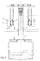
- Fig. 3 shows a maximum upwardly moved position of the holding member 5 and the electrode 4, in which no arc is operated.
- the maximum stroke of the holding member 5 between the lowest position in Fig. 1 and the topmost position in Fig. 3 is 16 m.
- the vessel 1 has a taphole for the slag on a level A and a taphole for the molten metal on a level B.
- the level of slag C is identical to the level of the tap hole.
- the level of slag C is above the tap hole.
- Fig. 1 and Fig. 2 is a level of the molten metal D above the tap hole for the melt B.
- the arrangement of the electrode 4 described above is the first choice in particular for processes in which a rapid change in the electrical resistances and thus in the electrode current is important. This is primarily the case in driving modes in which the energy is partially introduced with the resistance of an arc. Since the arc is somewhat unstable in nature, either the electrode position or the electrode current must be continuously adjusted in order to keep the applied power constant.
- the present arrangement makes it possible either to dispense with complex converter technology (in this case primarily ferro-nickel SAF), or the control can be improved by the possibility of very fast electrode positioning (eg FeCr - or TiO 2 - DC-SAF) ).
Landscapes
- Engineering & Computer Science (AREA)
- Power Engineering (AREA)
- Physics & Mathematics (AREA)
- Plasma & Fusion (AREA)
- Vertical, Hearth, Or Arc Furnaces (AREA)
- Furnace Details (AREA)
Description
- Die Erfindung betrifft eine Vorrichtung zur Regulierung der Elektrode eines Elektro-Reduktionsofens nach dem Oberbegriff des Anspruchs 1.
- Die
DE 1 083 952 und dieUS 3 042 731 A beschreiben eine Regelanordnung für Elektroden von Reduktionsöfen ohne Gegengewichte, bei der die Elektrode an einem Tragseil gehalten ist, welches mit einem Antriebsmotor In Verbindung steht. - Weiterhin ist es in den letzten Jahren bekannt, große Elektroden in Reduktionsöfen zu verwenden, wobei die Halterung und Bewegung der großen Elektroden mittels hydraulischer Zylinder erfolgt, um die großen Gewichte ausreichend schnell und sicher zu bewegen.
- Es ist die Aufgabe der Erfindung, eine Vorrichtung zur Regulierung der Elektrode eines Elektro-Reduktionsofens anzugeben, die auf einfache Weise eine schnelle und sichere Bewegung der Elektroden ermöglicht.
- Diese Aufgabe wird für eine eingangs genannte Vorrichtung erfindungsgemäß mit den kennzeichnenden Merkmalen des Anspruchs 1 gelöst. Durch die Veränderbarkeit der Masse des Gegengewichts kann bei Bedarf eine Anpassung an das Gewicht der Elektrode erfolgen, so dass eine resultierende, auf den Elektromotor wirkende Gesamtkraft einstellbar und nachregelbar ist. Dies ermöglicht eine besonders effektive Regelung der Elektrodenhöhe, auch im Fall besonders großer und schwerer Elektroden.
- Durch die Erfindung wird daher insbesondere die Möglichkeit geschaffen, auch große und schwere Elektroden mittels eines angetriebenen Tragseils zu verfahren, so dass auf hydraulische Zylinder für die Elektrodenanhebung verzichtet werden kann.
- Bei einer bevorzugten Weiterbildung der Erfindung ist es vorgesehen, dass die Masse des Gegengewichts durch ein strömungsfähiges Gewichtsgut, bevorzugt eine Flüssigkeit, veränderbar ist. Hierdurch ist eine insbesondere automatisierte und genaue Anpassung des Gegengewichts ermöglicht. Bei der Flüssigkeit kann es sich auf einfache Weise um Wasser handeln. Es kann sich in alternativer Gestaltung aber auch um ein nicht flüssiges, zum Beispiel rieselfähiges, Gewichtsgut handeln, wie etwa Sand, Metallgriess oder Ähnliches.
- Bei einer besonders bevorzugten Weiterbildung ist dabei das Gegengewicht über eine bevorzugt automatische Kupplung an eine Befüllungseinrichtung für das Gewichtsgut lösbar anschließbar. So kann eine weitere Automatisierung der Massenänderung des Gegengewichtes erfolgen. Eine Ankopplung kann zum Beispiel in einer oberen Position der Elektrode erfolgen, in der insbesondere kein Strom durch die Elektrode fließt. Alternativ kann eine Änderung des Gegengewichts auch während eines Betriebs der Elektrode vorgesehen sein.
- Bei einer möglichen Ausführungsform der Erfindung ist die Elektrode als selbsttragende Massivelektrode aus Kohlenstoff mit einem Durchmesser von mehr als 0,4 m, insbesondere mehr als 0,6 m, ausgebildet. Für Elektroden eines solchen Durchmessers und entsprechenden Gewichts wird durch die erfindungsgemäßen Merkmale eine Kombination mit einer Halterung durch ein Tragseil ermöglicht. Bei einer alternativen Ausgestaltung ist die Elektrode mit gleicher Zielsetzung als Söderberg-Elektrode mit einem Durchmesser von mehr 0,7 m, insbesondere mehr als 1,0 m, ausgebildet.
- Allgemein vorteilhaft beträgt ein maximaler Verfahrhub der Elektrode mittels des Tragseils mehr als 10 m, insbesondere mehr als 12 m. Durch die erfindungsgemäße Halterung der Elektrode wird ein solch großer Hub kostengünstig und auf einfache Weise ermöglicht.
- Besonders bevorzugt ist es bei einer erfindungsgemäßen Vorrichtung vorgesehen, dass ein Deckelherz des Reduktionsofens bei einer oberen Verfahrposition der am Tragseil gehaltenen Elektrode auswechselbar ist. Eine solche regelmäßige Auswechselung ist insbesondere bei Reduktionsöfen der Bauart DC-SAF vorgesehen und durch die erfindungsmäße Elektrodenhalterung gut realisierbar.
- Allgemein vorteilhaft ist der Elektromotor mittels einer rechnergestützten Steuerung ansteuerbar, um ein Nachführen der Elektrode im Betrieb des Reduktionsofen zu optimieren..
- Bei einer bevorzugten Detailgestaltung ist es vorgesehen, dass die Elektrode mittels zumindest zwei Tragseilen mit jeweils einem Gegengewicht gehalten ist. Hierdurch können die einzelnen Tragseile kleiner ausgelegt werden und es wird eine zusätzliche Betriebsicherheit ermöglicht.
- Zur weiteren Automatisierung ist es vorgesehen, dass das Tragseil über zumindest eine Wiegezelle geführt ist, um eine Gewichtsbelastung durch die Elektrode zu messen.-Hierdurch kann nicht nur eine optimale Anpassung des Gegengewichts erreicht werden, sondern zudem eine Abnutzung der Elektrode während des Betriebs engmaschig kontrolliert werden.
- Allgemein vorteilhaft ist das Gegengewicht so eingestellt, dass eine resultierende Kraft in Aufwärtsrichtung auf die Elektrode wirkt. Hierdurch kann die Elektrode im Fall eines Stromausfalls nicht in die Schmelze fallen bzw. kann durch die Schwerkraft selbstständig in eine obere Position verfahren.
- Weitere Vorteile und Merkmale der Erfindung ergeben sich aus dem nachfolgend beschriebenen Ausführungsbeispiel sowie aus den abhängigen Ansprüchen. Nachfolgend wird ein bevorzugtes Ausführungsbeispiel der erfindungsgemäßen Vorrichtung beschrieben und anhand der anliegenden Zeichnungen näher erläutert.
- Fig. 1
- zeigt eine teilweise geschnittene Gesamtansicht einer erfindungsgemäßen Vorrichtung in einer untersten Arbeitsposition einer Elektrode.
- Fig. 2
- zeigt die Vorrichtung aus
Fig. 1 in einer obersten Arbeitsposition der Elektrode. - Fig. 3
- zeigt die Vorrichtung aus
Fig. 1 in einer maximal oberen Position der Elektrode. - Die in
Fig. 1 gezeigte Vorrichtung stellt insgesamt einen DC-SAF (DC = Gleichstrom, SAF = Submerged Arc Furnace) dar. Bei dieser Bauart von Elektro-Reduktionsöfen taucht die Elektrode zumindest teilweise in die auf der Metallschmelze schwimmende Schlacke ein. - Der Reduktionsofen umfasst hat ein Gefäß 1 mit einem Deckel 2, in dem ein auswechselbares Deckelherz 3 angeordnet ist. Das Deckelherz 3 hat eine zentrale Öffnung 3a, die von einer Elektrode 4, vorliegend einer massiven Graphit-Elektrode mit einem Durchmesser von 0,75 m, durchgriffen wird.
- Die Elektrode 4 ist in einem Halteglied 5 festgelegt, das oberhalb des Deckels 2 zwischen ortfesten, senkrechten Führungen 6 geführt ist. Hierzu hat das Halteglied 5 seitliche, gegen die Führungen 6 wirkende Stützrollen 5a.
- Das die Elektrode aufnehmende Halteglied 5 ist über vorliegend zwei Tragseile 7 in der senkrechten bzw. Schwerkraftrichtung gehalten. Die Tragseile können je nach Anforderungen aus Stahlselen, Stahlbändern oder einem anderen Material sein, zum Beispiel Polyurethan-Gurte.
- Die Tragseile führen nach oben zu einer Bühne 8, wo sie jeweils in einer ersten Umlenkrolle 9 aufgenommen sind und um 90° umgelenkt werden. Nachfolgend durchlaufen die Tragseile 7 jeweils ein Antriebsglied 10 mit einem Elektromotor, der elektronisch über einen Rechner gesteuert ist. Nach dem Antriebsglied 10 folgt eine weitere Umlenkrolle 11, über die das Tragseil um 90° nach unten in Richtung eines Gegengewichts 12 geführt wird. An dem Gegengewicht 12 wird das Tragseil 7 in Umlenkrollen 13 um 180° umgelenkt und zu einer letzten, fixen Rolle 14 wieder nach oben geführt.
- Das Gegengewicht 12 ist über Stützrollen 12a seitlich gegen senkrechte Führungen 15 abgestützt. Es ist über die zuvor beschriebene Anordnung nach Art eines Flaschenzugs mit der Elektrode 4 verbunden, so dass ein bestimmter Hub eines der Gegengewichte 12 jeweils dem doppelten Hub der Elektrode entspricht.
- Zumindest jeweils eine, insbesondere jede der Rollen 9, 11, 14 ist als eine Wiegezelle ausgebildet, um die Gewichtskräfte der Gegengewichte 12 und der Elektrode 4 bzw. deren Differenz zu bestimmen.
- Falls diese Kräfte von vorbestimmten Sollwerten abweichen, können die Gegengewichte 12 durch Wasser als Gewichtsflüssigkeit verändert werden. Hierzu ist an jeder der Gegengewichtsanordnungen 12, 15 ein Drucktank 16 mit Wasser vorgesehen. Der Drucktank 16 ist über eine Leitung 17 mit einer automatischen Kupplung 18 verbunden, die in einer unteren Position des Gegengewichts 12 bzw. einer oberen Position der Elektrode 4 (siehe
Fig. 3 ) mit einer Gegenkupplung 19 an dem Gegengewicht 12 verkoppelt. Die Gegenkupplung 19 ist in einem unteren Bereich des Gegengewichts 12 angeordnet. In dem Gegengewicht 12 ist ein Hohlraum vorgesehen, der über den Drucktank 16 im angekoppelten Zustand in definierter Menge mit Wasser als Gewichtsgut befüllt werden kann. Hierdurch können nach Installation einer neuen Elektrode und in Unterbrechungen des Elektrodenbetriebs die gewünschten Gewichtsverhältnisse von Elektrode 4 und Gegengewichten 12 bereitgestellt werden. Insbesondere können ein Abbrand oder eine sonstige Gewichtsveränderung der Elektrode zu regelmäßigen Zeitpunkten kompensiert werden. -
Fig. 1 undFig. 2 zeigen jeweils eine maximal untere und eine maximal obere Arbeitsposition der Elektrode 4 bzw. des Halteglieds 5. Zwischen diesen Positionen liegt ein Hub des Arbeitsglieds um 1,8 m. In diesem Bereich kann die Elektrodenhöhe während des Betriebs in Abhängigkeit von der Abnutzung nachgefahren und mit hoher Geschwindigkeit geregelt werden, um den Lichtbogen konstant zu halten. -
Fig. 3 zeigt eine maximal nach oben verfahrene Position des Haltglieds 5 bzw. der Elektrode 4, bei der kein Lichtbogen mehr betrieben wird. Der maximale Hub des Halteglieds 5 zwischen der untersten Position inFig. 1 und der obersten Position inFig. 3 beträgt 16 m. - In der Position nach
Fig. 3 ist die Elektrode vollständig aus dem Deckelherz 3 ausgefahren, so dass dieses auf einfache Weise entnommen werden kann. Zudem sind die Kupplungen 19 der Gegengewichte an die Kupplungen 18 der Wassertanks 16 automatisch angeschlossen, so dass die Gegengewichte 12 durch Ablassen oder Befüllen mit Wasser verändert werden können. - Das Gefäß 1 hat eine Abstichöffnungen für die Schlacke auf einer Ebene A und eine Abstichöffnung für die Metallschmelze auf einer Ebene B. Im Betriebszustand nach
Fig. 1 ist der Stand der Schlacke C mit der Ebene der Abstichöffnung identisch. InFig. 2 liegt die Ebene der Schlacke C oberhalb der Abstichöffnung. In beiden Fällen (Fig. 1 undFig. 2 ) liegt eine Ebene der Metallschmelze D oberhalb der Abstichöffnung für die Schmelze B. - In
Fig. 3 liegen die Stände von Schlacke C und Schmelze D jeweils oberhalb ihrer Abstichöffnungen A, B. - Die vorstehend beschriebene Anordnung der Elektrode 4 ist insbesondere für Prozesse erste Wahl, in denen es auf eine schnelle Änderung der elektrischen Widerstände und somit des Elektrodenstroms ankommt. Dies ist vorrangig bei Fahrweisen der Fall, bei denen die Energie teilweise mit dem Widerstand eines Lichtbogens eingebracht wird. Da der Lichtbogen seiner Art nach etwas instabil ist, müssen entweder laufend die Elektrodenposition oder der Elektrodenstrom angepasst werden, um die eingebrachte Leistung konstant zu halten. Durch die vorliegende Anordnung kann entweder auf eine aufwändige Stromrichtertechnologie verzichtet werden (hier wird in erster Linie an Ferro-Nickel-SAF gedacht), oder die Steuerung kann durch die Möglichkeit sehr schneller Elektrodenpositionierung verbessert werden (z.B. FeCr - oder TiO2 - DC-SAF).
Claims (10)
- Vorrichtung zur Regulierung der Elektrode eines Elektro-Reduktionsofens, umfassend
eine senkrecht ausgerichtete Elektrode (4), die von oben in ein Gefäß (1) des Reduktionsofens einfahrbar ist,
wobei die Elektrode (4) über ein Tragseil (7) mit einem Gegengewicht (12) gehalten ist, und
wobei das Tragseil (7) über einen Elektromotor (10) antreibbar ist,
dadurch gekennzeichnet,
dass das Gegengewicht (12) in seiner Masse veränderbar ist. - Vorrichtung nach Anspruch 1, dadurch gekennzeichnet, dass die Masse des Gegengewichts (12) durch ein strömungsfähiges Gewichtsgut, insbesondere eine Flüssigkeit, veränderbar ist.
- Vorrichtung nach Anspruch 2, dadurch gekennzeichnet, dass das Gegengewicht (12) über eine insbesondere automatische Kupplung (18, 19) an eine Befüllungseinrichtung (16, 17) für das Gewichtsgut lösbar anschließbar ist.
- Vorrichtung nach einem der vorhergehenden Ansprüche, dadurch gekennzeichnet, dass die Elektrode (4) als selbsttragende Massivelektrode aus Kohlenstoff mit einem Durchmesser von mehr als 0,4 m, insbesondere mehr als 0,6 m, beträgt.
- Vorrichtung nach einem der Ansprüche 1 bis 3, dadurch gekennzeichnet, dass die Elektrode (4) als Söderberg-Elektrode mit einem Durchmesser von mehr 0,7 m, insbesondere mehr als 1,0 m, ausgebildet ist.
- Vorrichtung nach einem der vorhergehenden Ansprüche, dadurch gekennzeichnet, dass ein maximaler Verfahrhub der Elektrode (4) mittels des Tragseils (7) mehr als 10 m, insbesondere mehr als 12 m, beträgt.
- Vorrichtung nach einem der vorhergehenden Ansprüche, dadurch gekennzeichnet, dass ein Deckelherz (3) des Reduktionsofens bei einer oberen Verfahrposition der am Tragseil (7) gehaltenen Elektrode (4) auswechselbar ist.
- Vorrichtung nach einem der vorhergehenden Ansprüche, dadurch gekennzeichnet, dass der Elektromotor (10) mittels einer rechnergestützten Steuerung ansteuerbar ist.
- Vorrichtung nach einem der vorhergehenden Ansprüche, dadurch gekennzeichnet, dass die Elektrode (4) mittels zumindest zwei Tragseilen (7) mit jeweils einem Gegengewicht (12) gehalten ist.
- Vorrichtung nach einem der vorhergehenden Ansprüche, dadurch gekennzeichnet, dass das Tragseil (7) über zumindest eine Wiegezelle (9, 11, 14) geführt ist, um eine Gewichtsbelastung durch die Elektrode (4) zu messen.
Applications Claiming Priority (2)
| Application Number | Priority Date | Filing Date | Title |
|---|---|---|---|
| DE102011003468A DE102011003468A1 (de) | 2011-02-01 | 2011-02-01 | Vorrichtung zur Regulierung der Elektrode eines Elektro-Reduktionsofens |
| PCT/EP2012/051610 WO2012104323A1 (de) | 2011-02-01 | 2012-01-31 | Vorrichtung zur regulierung der elektrode eines elektro-reduktionsofens |
Publications (2)
| Publication Number | Publication Date |
|---|---|
| EP2671426A1 EP2671426A1 (de) | 2013-12-11 |
| EP2671426B1 true EP2671426B1 (de) | 2015-03-18 |
Family
ID=45569609
Family Applications (1)
| Application Number | Title | Priority Date | Filing Date |
|---|---|---|---|
| EP12703046.8A Not-in-force EP2671426B1 (de) | 2011-02-01 | 2012-01-31 | Vorrichtung zur regulierung der elektrode eines elektro-reduktionsofens |
Country Status (5)
| Country | Link |
|---|---|
| EP (1) | EP2671426B1 (de) |
| CA (1) | CA2823756C (de) |
| DE (1) | DE102011003468A1 (de) |
| WO (1) | WO2012104323A1 (de) |
| ZA (1) | ZA201305764B (de) |
Family Cites Families (6)
| Publication number | Priority date | Publication date | Assignee | Title |
|---|---|---|---|---|
| US1528510A (en) * | 1922-08-28 | 1925-03-03 | Bbc Brown Boveri & Cie | Automatic regulating apparatus for electric furnaces |
| FR707595A (fr) * | 1929-12-19 | 1931-07-09 | Brown | Four de fusion électrique à électrodes commandées par l'intermédiaire d'un fluide sous pression |
| US3042731A (en) | 1958-08-05 | 1962-07-03 | Heraeus Gmbh W C | Movement mechanism for electrode control in vacuum arc furnaces |
| DE1083952B (de) | 1959-05-20 | 1960-06-23 | Licentia Gmbh | Regeleinrichtung fuer Elektroden ohne Gegengewicht bei Elektrooefen |
| SU864598A1 (ru) * | 1979-11-15 | 1981-09-15 | Специальное Конструкторское Бюро "Азерэлектротерм" | Устройство дл перемещени расходуемого электрода |
| CN201550313U (zh) * | 2009-09-17 | 2010-08-11 | 宝山钢铁股份有限公司 | 一种钛合金自耗电极集成装置 |
-
2011
- 2011-02-01 DE DE102011003468A patent/DE102011003468A1/de not_active Withdrawn
-
2012
- 2012-01-31 CA CA2823756A patent/CA2823756C/en not_active Expired - Fee Related
- 2012-01-31 WO PCT/EP2012/051610 patent/WO2012104323A1/de not_active Ceased
- 2012-01-31 EP EP12703046.8A patent/EP2671426B1/de not_active Not-in-force
-
2013
- 2013-07-31 ZA ZA2013/05764A patent/ZA201305764B/en unknown
Also Published As
| Publication number | Publication date |
|---|---|
| WO2012104323A1 (de) | 2012-08-09 |
| CA2823756C (en) | 2016-01-12 |
| DE102011003468A1 (de) | 2012-08-02 |
| CA2823756A1 (en) | 2012-08-09 |
| EP2671426A1 (de) | 2013-12-11 |
| ZA201305764B (en) | 2014-03-26 |
Similar Documents
| Publication | Publication Date | Title |
|---|---|---|
| EP2059758B9 (de) | Schmelzofen, insbesondere lichtbogenofen | |
| EP2500085A1 (de) | Höhenverstellvorrichtung für ein getauchtes Rühr- oder Pumpwerk | |
| DE2846630A1 (de) | Vorrichtung zum anheben des bodens von kannen | |
| DE1963147B2 (de) | Lagerung von verteilerrinnen an einer karussellvorrichtung fuer giesspfannen bei stranggiessanlagen | |
| CH689728A5 (de) | Vorrichtung zum Regeln eines Zuflusses einer Metallschmelze mittels eines Stopfens. | |
| EP2602890A2 (de) | Anordnung eines Energiezuführungskabels zwischen einem feststehenden Unterbau und einem darauf drehbaren Oberbau eines Tagebaugerätes | |
| EP4177555A1 (de) | Schlackentüranordnung und reinigungsverfahren | |
| WO2012104323A1 (de) | Vorrichtung zur regulierung der elektrode eines elektro-reduktionsofens | |
| DE102016100372A1 (de) | Umschmelzanlage | |
| WO2020156856A1 (de) | Klemm- und hubvorrichtung | |
| DE1949995A1 (de) | Zwischenbehaelter (Tundish) fuer Stranggiessanlagen | |
| DE19933771B4 (de) | Kran | |
| EP2859293B1 (de) | Lichtbogenofen | |
| DE102010046558B3 (de) | Vorrichtung zum Texturieren einer Walze | |
| DE102010046557B4 (de) | Vorrichtung zum Texturieren einer Walze | |
| DE2728561B2 (de) | Kulisse zur Steuerung von an einem rotierenden Aggregat angeordneten Mechanismen, insbesondere von Mantelgasdüsen an einem Drehrohrofen | |
| DE20103016U1 (de) | Hebe- und Tragvorrichtung mit einem Tragbalken | |
| DE2223109C2 (de) | Räumvorrichtung für die Rückverladung von Schüttgut aus Schlitzbunkern | |
| DE102004034704B3 (de) | Vorrichtung zum Wechseln der Pfannen bei Stranggießanlagen | |
| DE2651544A1 (de) | Einrichtung zum kontinuierlichen nachstellen der elektrode in elektrooefen | |
| DE20120381U1 (de) | Hebebühne für runde, konische Bauwerke | |
| DE4027822C1 (en) | Adjusting appts. for heaped material handler - raises, lowers or adjusts slope angle of rakes using electric cable drive for each rake | |
| DE2010322A1 (en) | Calender stack pressurising and depressurising - means | |
| WO2019158419A1 (de) | Umschmelzanlage und verfahren zum betrieb einer umschmelzanlage | |
| DE901586C (de) | Giesswagen |
Legal Events
| Date | Code | Title | Description |
|---|---|---|---|
| PUAI | Public reference made under article 153(3) epc to a published international application that has entered the european phase |
Free format text: ORIGINAL CODE: 0009012 |
|
| 17P | Request for examination filed |
Effective date: 20130802 |
|
| AK | Designated contracting states |
Kind code of ref document: A1 Designated state(s): AL AT BE BG CH CY CZ DE DK EE ES FI FR GB GR HR HU IE IS IT LI LT LU LV MC MK MT NL NO PL PT RO RS SE SI SK SM TR |
|
| DAX | Request for extension of the european patent (deleted) | ||
| GRAP | Despatch of communication of intention to grant a patent |
Free format text: ORIGINAL CODE: EPIDOSNIGR1 |
|
| INTG | Intention to grant announced |
Effective date: 20141120 |
|
| GRAS | Grant fee paid |
Free format text: ORIGINAL CODE: EPIDOSNIGR3 |
|
| GRAA | (expected) grant |
Free format text: ORIGINAL CODE: 0009210 |
|
| AK | Designated contracting states |
Kind code of ref document: B1 Designated state(s): AL AT BE BG CH CY CZ DE DK EE ES FI FR GB GR HR HU IE IS IT LI LT LU LV MC MK MT NL NO PL PT RO RS SE SI SK SM TR |
|
| REG | Reference to a national code |
Ref country code: GB Ref legal event code: FG4D Free format text: NOT ENGLISH |
|
| REG | Reference to a national code |
Ref country code: CH Ref legal event code: EP Ref country code: DE Ref legal event code: R082 Ref document number: 502012002571 Country of ref document: DE Representative=s name: HEMMERICH & KOLLEGEN, DE |
|
| REG | Reference to a national code |
Ref country code: IE Ref legal event code: FG4D Free format text: LANGUAGE OF EP DOCUMENT: GERMAN |
|
| REG | Reference to a national code |
Ref country code: AT Ref legal event code: REF Ref document number: 717246 Country of ref document: AT Kind code of ref document: T Effective date: 20150415 |
|
| REG | Reference to a national code |
Ref country code: DE Ref legal event code: R096 Ref document number: 502012002571 Country of ref document: DE Effective date: 20150423 |
|
| REG | Reference to a national code |
Ref country code: NL Ref legal event code: VDEP Effective date: 20150318 |
|
| RAP2 | Party data changed (patent owner data changed or rights of a patent transferred) |
Owner name: SMS GROUP GMBH |
|
| REG | Reference to a national code |
Ref country code: NL Ref legal event code: VDEP Effective date: 20150318 |
|
| PG25 | Lapsed in a contracting state [announced via postgrant information from national office to epo] |
Ref country code: NO Free format text: LAPSE BECAUSE OF FAILURE TO SUBMIT A TRANSLATION OF THE DESCRIPTION OR TO PAY THE FEE WITHIN THE PRESCRIBED TIME-LIMIT Effective date: 20150618 Ref country code: SE Free format text: LAPSE BECAUSE OF FAILURE TO SUBMIT A TRANSLATION OF THE DESCRIPTION OR TO PAY THE FEE WITHIN THE PRESCRIBED TIME-LIMIT Effective date: 20150318 Ref country code: HR Free format text: LAPSE BECAUSE OF FAILURE TO SUBMIT A TRANSLATION OF THE DESCRIPTION OR TO PAY THE FEE WITHIN THE PRESCRIBED TIME-LIMIT Effective date: 20150318 Ref country code: LT Free format text: LAPSE BECAUSE OF FAILURE TO SUBMIT A TRANSLATION OF THE DESCRIPTION OR TO PAY THE FEE WITHIN THE PRESCRIBED TIME-LIMIT Effective date: 20150318 Ref country code: FI Free format text: LAPSE BECAUSE OF FAILURE TO SUBMIT A TRANSLATION OF THE DESCRIPTION OR TO PAY THE FEE WITHIN THE PRESCRIBED TIME-LIMIT Effective date: 20150318 |
|
| REG | Reference to a national code |
Ref country code: DE Ref legal event code: R082 Ref document number: 502012002571 Country of ref document: DE Representative=s name: HEMMERICH & KOLLEGEN, DE Ref country code: DE Ref legal event code: R081 Ref document number: 502012002571 Country of ref document: DE Owner name: SMS GROUP GMBH, DE Free format text: FORMER OWNER: SMS SIEMAG AG, 40237 DUESSELDORF, DE |
|
| REG | Reference to a national code |
Ref country code: LT Ref legal event code: MG4D |
|
| PG25 | Lapsed in a contracting state [announced via postgrant information from national office to epo] |
Ref country code: RS Free format text: LAPSE BECAUSE OF FAILURE TO SUBMIT A TRANSLATION OF THE DESCRIPTION OR TO PAY THE FEE WITHIN THE PRESCRIBED TIME-LIMIT Effective date: 20150318 Ref country code: GR Free format text: LAPSE BECAUSE OF FAILURE TO SUBMIT A TRANSLATION OF THE DESCRIPTION OR TO PAY THE FEE WITHIN THE PRESCRIBED TIME-LIMIT Effective date: 20150619 Ref country code: LV Free format text: LAPSE BECAUSE OF FAILURE TO SUBMIT A TRANSLATION OF THE DESCRIPTION OR TO PAY THE FEE WITHIN THE PRESCRIBED TIME-LIMIT Effective date: 20150318 |
|
| PG25 | Lapsed in a contracting state [announced via postgrant information from national office to epo] |
Ref country code: NL Free format text: LAPSE BECAUSE OF FAILURE TO SUBMIT A TRANSLATION OF THE DESCRIPTION OR TO PAY THE FEE WITHIN THE PRESCRIBED TIME-LIMIT Effective date: 20150318 |
|
| PG25 | Lapsed in a contracting state [announced via postgrant information from national office to epo] |
Ref country code: ES Free format text: LAPSE BECAUSE OF FAILURE TO SUBMIT A TRANSLATION OF THE DESCRIPTION OR TO PAY THE FEE WITHIN THE PRESCRIBED TIME-LIMIT Effective date: 20150318 Ref country code: EE Free format text: LAPSE BECAUSE OF FAILURE TO SUBMIT A TRANSLATION OF THE DESCRIPTION OR TO PAY THE FEE WITHIN THE PRESCRIBED TIME-LIMIT Effective date: 20150318 Ref country code: SK Free format text: LAPSE BECAUSE OF FAILURE TO SUBMIT A TRANSLATION OF THE DESCRIPTION OR TO PAY THE FEE WITHIN THE PRESCRIBED TIME-LIMIT Effective date: 20150318 Ref country code: CZ Free format text: LAPSE BECAUSE OF FAILURE TO SUBMIT A TRANSLATION OF THE DESCRIPTION OR TO PAY THE FEE WITHIN THE PRESCRIBED TIME-LIMIT Effective date: 20150318 Ref country code: PT Free format text: LAPSE BECAUSE OF FAILURE TO SUBMIT A TRANSLATION OF THE DESCRIPTION OR TO PAY THE FEE WITHIN THE PRESCRIBED TIME-LIMIT Effective date: 20150720 Ref country code: RO Free format text: LAPSE BECAUSE OF FAILURE TO SUBMIT A TRANSLATION OF THE DESCRIPTION OR TO PAY THE FEE WITHIN THE PRESCRIBED TIME-LIMIT Effective date: 20150318 |
|
| PG25 | Lapsed in a contracting state [announced via postgrant information from national office to epo] |
Ref country code: IS Free format text: LAPSE BECAUSE OF FAILURE TO SUBMIT A TRANSLATION OF THE DESCRIPTION OR TO PAY THE FEE WITHIN THE PRESCRIBED TIME-LIMIT Effective date: 20150718 Ref country code: PL Free format text: LAPSE BECAUSE OF FAILURE TO SUBMIT A TRANSLATION OF THE DESCRIPTION OR TO PAY THE FEE WITHIN THE PRESCRIBED TIME-LIMIT Effective date: 20150318 |
|
| REG | Reference to a national code |
Ref country code: DE Ref legal event code: R097 Ref document number: 502012002571 Country of ref document: DE |
|
| PG25 | Lapsed in a contracting state [announced via postgrant information from national office to epo] |
Ref country code: IT Free format text: LAPSE BECAUSE OF FAILURE TO SUBMIT A TRANSLATION OF THE DESCRIPTION OR TO PAY THE FEE WITHIN THE PRESCRIBED TIME-LIMIT Effective date: 20150318 |
|
| PLBE | No opposition filed within time limit |
Free format text: ORIGINAL CODE: 0009261 |
|
| STAA | Information on the status of an ep patent application or granted ep patent |
Free format text: STATUS: NO OPPOSITION FILED WITHIN TIME LIMIT |
|
| PG25 | Lapsed in a contracting state [announced via postgrant information from national office to epo] |
Ref country code: DK Free format text: LAPSE BECAUSE OF FAILURE TO SUBMIT A TRANSLATION OF THE DESCRIPTION OR TO PAY THE FEE WITHIN THE PRESCRIBED TIME-LIMIT Effective date: 20150318 |
|
| 26N | No opposition filed |
Effective date: 20151221 |
|
| PG25 | Lapsed in a contracting state [announced via postgrant information from national office to epo] |
Ref country code: SI Free format text: LAPSE BECAUSE OF FAILURE TO SUBMIT A TRANSLATION OF THE DESCRIPTION OR TO PAY THE FEE WITHIN THE PRESCRIBED TIME-LIMIT Effective date: 20150318 |
|
| PG25 | Lapsed in a contracting state [announced via postgrant information from national office to epo] |
Ref country code: BE Free format text: LAPSE BECAUSE OF NON-PAYMENT OF DUE FEES Effective date: 20160131 |
|
| PG25 | Lapsed in a contracting state [announced via postgrant information from national office to epo] |
Ref country code: LU Free format text: LAPSE BECAUSE OF FAILURE TO SUBMIT A TRANSLATION OF THE DESCRIPTION OR TO PAY THE FEE WITHIN THE PRESCRIBED TIME-LIMIT Effective date: 20160131 |
|
| REG | Reference to a national code |
Ref country code: CH Ref legal event code: PL |
|
| GBPC | Gb: european patent ceased through non-payment of renewal fee |
Effective date: 20160131 |
|
| PG25 | Lapsed in a contracting state [announced via postgrant information from national office to epo] |
Ref country code: MC Free format text: LAPSE BECAUSE OF FAILURE TO SUBMIT A TRANSLATION OF THE DESCRIPTION OR TO PAY THE FEE WITHIN THE PRESCRIBED TIME-LIMIT Effective date: 20150318 |
|
| REG | Reference to a national code |
Ref country code: FR Ref legal event code: ST Effective date: 20160930 |
|
| PG25 | Lapsed in a contracting state [announced via postgrant information from national office to epo] |
Ref country code: CH Free format text: LAPSE BECAUSE OF NON-PAYMENT OF DUE FEES Effective date: 20160131 Ref country code: GB Free format text: LAPSE BECAUSE OF NON-PAYMENT OF DUE FEES Effective date: 20160131 Ref country code: LI Free format text: LAPSE BECAUSE OF NON-PAYMENT OF DUE FEES Effective date: 20160131 |
|
| REG | Reference to a national code |
Ref country code: IE Ref legal event code: MM4A |
|
| PG25 | Lapsed in a contracting state [announced via postgrant information from national office to epo] |
Ref country code: FR Free format text: LAPSE BECAUSE OF NON-PAYMENT OF DUE FEES Effective date: 20160201 |
|
| PG25 | Lapsed in a contracting state [announced via postgrant information from national office to epo] |
Ref country code: IE Free format text: LAPSE BECAUSE OF NON-PAYMENT OF DUE FEES Effective date: 20160131 |
|
| PG25 | Lapsed in a contracting state [announced via postgrant information from national office to epo] |
Ref country code: MT Free format text: LAPSE BECAUSE OF FAILURE TO SUBMIT A TRANSLATION OF THE DESCRIPTION OR TO PAY THE FEE WITHIN THE PRESCRIBED TIME-LIMIT Effective date: 20150318 |
|
| REG | Reference to a national code |
Ref country code: AT Ref legal event code: MM01 Ref document number: 717246 Country of ref document: AT Kind code of ref document: T Effective date: 20170131 |
|
| PG25 | Lapsed in a contracting state [announced via postgrant information from national office to epo] |
Ref country code: HU Free format text: LAPSE BECAUSE OF FAILURE TO SUBMIT A TRANSLATION OF THE DESCRIPTION OR TO PAY THE FEE WITHIN THE PRESCRIBED TIME-LIMIT; INVALID AB INITIO Effective date: 20120131 Ref country code: SM Free format text: LAPSE BECAUSE OF FAILURE TO SUBMIT A TRANSLATION OF THE DESCRIPTION OR TO PAY THE FEE WITHIN THE PRESCRIBED TIME-LIMIT Effective date: 20150318 Ref country code: CY Free format text: LAPSE BECAUSE OF FAILURE TO SUBMIT A TRANSLATION OF THE DESCRIPTION OR TO PAY THE FEE WITHIN THE PRESCRIBED TIME-LIMIT Effective date: 20150318 Ref country code: AT Free format text: LAPSE BECAUSE OF NON-PAYMENT OF DUE FEES Effective date: 20170131 |
|
| PG25 | Lapsed in a contracting state [announced via postgrant information from national office to epo] |
Ref country code: TR Free format text: LAPSE BECAUSE OF FAILURE TO SUBMIT A TRANSLATION OF THE DESCRIPTION OR TO PAY THE FEE WITHIN THE PRESCRIBED TIME-LIMIT Effective date: 20150318 Ref country code: MK Free format text: LAPSE BECAUSE OF FAILURE TO SUBMIT A TRANSLATION OF THE DESCRIPTION OR TO PAY THE FEE WITHIN THE PRESCRIBED TIME-LIMIT Effective date: 20150318 |
|
| PG25 | Lapsed in a contracting state [announced via postgrant information from national office to epo] |
Ref country code: BG Free format text: LAPSE BECAUSE OF FAILURE TO SUBMIT A TRANSLATION OF THE DESCRIPTION OR TO PAY THE FEE WITHIN THE PRESCRIBED TIME-LIMIT Effective date: 20150318 |
|
| PG25 | Lapsed in a contracting state [announced via postgrant information from national office to epo] |
Ref country code: AL Free format text: LAPSE BECAUSE OF FAILURE TO SUBMIT A TRANSLATION OF THE DESCRIPTION OR TO PAY THE FEE WITHIN THE PRESCRIBED TIME-LIMIT Effective date: 20150318 |
|
| PGFP | Annual fee paid to national office [announced via postgrant information from national office to epo] |
Ref country code: DE Payment date: 20190123 Year of fee payment: 8 |
|
| REG | Reference to a national code |
Ref country code: DE Ref legal event code: R119 Ref document number: 502012002571 Country of ref document: DE |
|
| PG25 | Lapsed in a contracting state [announced via postgrant information from national office to epo] |
Ref country code: DE Free format text: LAPSE BECAUSE OF NON-PAYMENT OF DUE FEES Effective date: 20200801 |