EP2669867A2 - Vorrichtung und Verfahren zur Anzeige von Fahrer-Hilfsinformationen - Google Patents
Vorrichtung und Verfahren zur Anzeige von Fahrer-Hilfsinformationen Download PDFInfo
- Publication number
- EP2669867A2 EP2669867A2 EP13275121.5A EP13275121A EP2669867A2 EP 2669867 A2 EP2669867 A2 EP 2669867A2 EP 13275121 A EP13275121 A EP 13275121A EP 2669867 A2 EP2669867 A2 EP 2669867A2
- Authority
- EP
- European Patent Office
- Prior art keywords
- guide line
- vehicle
- image
- steering angle
- storing unit
- Prior art date
- Legal status (The legal status is an assumption and is not a legal conclusion. Google has not performed a legal analysis and makes no representation as to the accuracy of the status listed.)
- Withdrawn
Links
- 238000000034 method Methods 0.000 title claims description 32
- 238000005516 engineering process Methods 0.000 description 8
- 230000008901 benefit Effects 0.000 description 2
- 239000000470 constituent Substances 0.000 description 2
- 238000011161 development Methods 0.000 description 2
- 238000012545 processing Methods 0.000 description 2
- 238000003462 Bender reaction Methods 0.000 description 1
- 238000004891 communication Methods 0.000 description 1
- 230000000694 effects Effects 0.000 description 1
- 230000007717 exclusion Effects 0.000 description 1
- 238000000605 extraction Methods 0.000 description 1
- 239000004973 liquid crystal related substance Substances 0.000 description 1
- 238000012986 modification Methods 0.000 description 1
- 230000004048 modification Effects 0.000 description 1
- 230000002194 synthesizing effect Effects 0.000 description 1
Images



Classifications
-
- B—PERFORMING OPERATIONS; TRANSPORTING
- B62—LAND VEHICLES FOR TRAVELLING OTHERWISE THAN ON RAILS
- B62D—MOTOR VEHICLES; TRAILERS
- B62D15/00—Steering not otherwise provided for
- B62D15/02—Steering position indicators ; Steering position determination; Steering aids
- B62D15/029—Steering assistants using warnings or proposing actions to the driver without influencing the steering system
- B62D15/0295—Steering assistants using warnings or proposing actions to the driver without influencing the steering system by overlaying a vehicle path based on present steering angle over an image without processing that image
-
- B—PERFORMING OPERATIONS; TRANSPORTING
- B60—VEHICLES IN GENERAL
- B60R—VEHICLES, VEHICLE FITTINGS, OR VEHICLE PARTS, NOT OTHERWISE PROVIDED FOR
- B60R21/00—Arrangements or fittings on vehicles for protecting or preventing injuries to occupants or pedestrians in case of accidents or other traffic risks
- B60R21/01—Electrical circuits for triggering passive safety arrangements, e.g. airbags, safety belt tighteners, in case of vehicle accidents or impending vehicle accidents
- B60R21/013—Electrical circuits for triggering passive safety arrangements, e.g. airbags, safety belt tighteners, in case of vehicle accidents or impending vehicle accidents including means for detecting collisions, impending collisions or roll-over
- B60R21/0134—Electrical circuits for triggering passive safety arrangements, e.g. airbags, safety belt tighteners, in case of vehicle accidents or impending vehicle accidents including means for detecting collisions, impending collisions or roll-over responsive to imminent contact with an obstacle, e.g. using radar systems
-
- B—PERFORMING OPERATIONS; TRANSPORTING
- B60—VEHICLES IN GENERAL
- B60W—CONJOINT CONTROL OF VEHICLE SUB-UNITS OF DIFFERENT TYPE OR DIFFERENT FUNCTION; CONTROL SYSTEMS SPECIALLY ADAPTED FOR HYBRID VEHICLES; ROAD VEHICLE DRIVE CONTROL SYSTEMS FOR PURPOSES NOT RELATED TO THE CONTROL OF A PARTICULAR SUB-UNIT
- B60W50/00—Details of control systems for road vehicle drive control not related to the control of a particular sub-unit, e.g. process diagnostic or vehicle driver interfaces
- B60W50/08—Interaction between the driver and the control system
- B60W50/14—Means for informing the driver, warning the driver or prompting a driver intervention
-
- B—PERFORMING OPERATIONS; TRANSPORTING
- B60—VEHICLES IN GENERAL
- B60R—VEHICLES, VEHICLE FITTINGS, OR VEHICLE PARTS, NOT OTHERWISE PROVIDED FOR
- B60R1/00—Optical viewing arrangements; Real-time viewing arrangements for drivers or passengers using optical image capturing systems, e.g. cameras or video systems specially adapted for use in or on vehicles
- B60R1/02—Rear-view mirror arrangements
- B60R1/08—Rear-view mirror arrangements involving special optical features, e.g. avoiding blind spots, e.g. convex mirrors; Side-by-side associations of rear-view and other mirrors
-
- B—PERFORMING OPERATIONS; TRANSPORTING
- B60—VEHICLES IN GENERAL
- B60W—CONJOINT CONTROL OF VEHICLE SUB-UNITS OF DIFFERENT TYPE OR DIFFERENT FUNCTION; CONTROL SYSTEMS SPECIALLY ADAPTED FOR HYBRID VEHICLES; ROAD VEHICLE DRIVE CONTROL SYSTEMS FOR PURPOSES NOT RELATED TO THE CONTROL OF A PARTICULAR SUB-UNIT
- B60W10/00—Conjoint control of vehicle sub-units of different type or different function
- B60W10/20—Conjoint control of vehicle sub-units of different type or different function including control of steering systems
Definitions
- the present invention relates to a device and method of displaying driving auxiliary information.
- Patent Document 1 a technology of allowing a vehicle to be more easily controlled at the time of backward movement of the vehicle by synthesizing an image photographed through a camera and a guide line image divided according to a steering angle of a handle with each other and then outputting the synthesized image to a display device has been introduced in Patent Document 1.
- Patent Document 1 even though an expected movement trajectory according to the steering angle may be displayed, information on whether or not an obstacle is positioned in a vehicle movement direction or information on a distance up to the corresponding obstacle has not been provided.
- Patent Document 2 a technology of displaying a distance between a vehicle and an obstacle and variably displaying a length of a dynamic vehicle path line according to the distance between the vehicle and the obstacle has been introduced in Patent Document 2.
- Patent Document 2 even though the distance between the vehicle and the obstacle may be informed in real time, the fact that the movement direction of the vehicle is changed according to the steering angle has not been reflected in information on the obstacle.
- a warning may be generated against an obstacle positioned at a position unrelated to the movement direction of the vehicle to confuse the driver.
- Patent Document 1 Korea Patent Laid-open Publication No. 10-2010-0129965
- Patent Document 2 Korea Patent Laid-open Publication No. 10-2011-0093726 .
- An object of the present invention is to provide a device of displaying driving auxiliary information capable of providing information on an obstacle positioned on an expected path on which a vehicle will move as well as the expected path according to a steering angle.
- Another object of the present invention is to provide a method of displaying driving auxiliary information capable of providing information on an obstacle positioned on an expected path on which a vehicle will move as well as the expected path according to a steering angle.
- a device of displaying driving auxiliary information including: a camera photographing a real image; a first storing unit in which a guide line image for a driving trajectory of a vehicle is divided for each steering angle and stored; a steering sensor detecting a steering angle of the vehicle; a plurality of distance sensors measuring distances to an object positioned at an outer portion of the vehicle and spaced apart from each other; and a controlling unit connected to the first storing unit, the steering sensor, and the distance sensors, whereby an image photographed in the camera, the guide line image according to the steering angle of the vehicle, and an object present at an internal region of a guide line are displayed.
- the controlling unit may include: a guide line extractor extracting the guide line image according to the steering angle detected in the steering sensor from the first storing unit; a position calculator calculating a position of the object using a plurality of distance values measured in the distance sensors; and a determinator determining whether or not the object is present at the internal region of the guide line, and only in the case in which the determinator determines that the object is present at the internal region of the guide line, the distance to the object is displayed at the internal region of the guide line.
- the guide line image stored in the first storing unit may be encoded in an MRLC format including color information, a data width, and a blank width.
- a device of displaying driving auxiliary information including: a first storing unit in which a guide line image for a driving trajectory of a vehicle is divided for each steering angle and stored; a second storing unit in which an object warning image to be displayed at each of the n divided regions of an inner portion of a guide line is divided and stored, with respect to each of the guide line images divided for each steering angle; a steering sensor detecting a steering angle of the vehicle; a plurality of distance sensors measuring distances to an object positioned at an outer portion of the vehicle and spaced apart from each other; and a controlling unit connected to the first storing unit, the second storing unit, the steering sensor, and the distance sensors, whereby an object present at an internal region of the guide line according to the steering angle of the vehicle is displayed.
- the controlling unit may include: a guide line extractor extracting the guide line image according to the steering angle detected in the steering sensor from the first storing unit; and an object warning image extractor calculating a position of the object using a plurality of distance values measured in the distance sensors and extracting an object warning image corresponding to the position of the object from the second storing unit to combine the guide line image and the object warning image with each other.
- the guide line image stored in the first storing unit and the object warning image stored in the second storing unit may be encoded in an MRLC format including color information, a data width, and a blank width.
- a method of displaying driving auxiliary information including: (A) dividing a guide line image for a driving trajectory of a vehicle for each steering angle and pre-storing the divided guide line images; (B) detecting a steering angle of the vehicle; (C) extracting a guide line image corresponding to the steering angle detected in step (B) among the guide line images for the driving trajectory of the vehicle; (D) measuring distances to an object positioned at an outer portion of the vehicle in each of a plurality of distance sensors spaced apart from each other; and (E) calculating a position of the object using a plurality of distance values measured in step (D), whereby an object present at an inner portion of a guide line is displayed together with the guide line.
- the position of the object calculated in step (E) corresponds to an internal region of the guide line
- the position of the object may be displayed at the inner portion of the guide line, and in the case in which the position of the object corresponds to an external region of the guide line, only the guide line may be displayed.
- the guide line image for the driving trajectory of the vehicle divided for each steering angle and pre-stored may be encoded in an MRLC format including color information, a data width, and a blank width, and step (C) may include decoding the guide line image encoded in the MRLC format.
- a method of displaying driving auxiliary information including: (a) dividing a guide line image for a driving trajectory of a vehicle for each steering angle and pre-storing the divided guide line images; (b) pre-storing object warning images to be displayed at each of the n divided regions of an inner portion of a guide line, with respect to each of the guide line images divided for each steering angle; (c) detecting a steering angle of the vehicle; (d) extracting a guide line image corresponding to the steering angle detected in step (c) among the guide line images for the driving trajectory of the vehicle; (e) measuring distances to an object positioned at an outer portion of the vehicle in each of a plurality of distance sensors spaced apart from each other; and (f) calculating a position of the object using a plurality of distance values measured in step (e) and extracting an object warning image corresponding to the position of the object among the object warning images, whereby an object present at an internal region of the guide line according to the steering angle
- the method may further include combining the guide line image extracted in step (d) and the object warning image extracted in step (f) with each other and outputting the combined image.
- the guide line image and the object warning image may be encoded in an MRLC format including color information, a data width, and a blank width, and step (d) or step (f) may include decoding the guide line image or the object warning image encoded in the MRLC format.
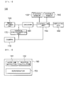
- FIG. 1 is a view schematically showing a device 100 of displaying driving auxiliary information according to an exemplary embodiment of the present invention.
- the device 100 of displaying driving auxiliary information may include a camera 110, a first storing unit 120, a steering sensor 130, a distance sensor 140, and a controlling unit 150.
- the camera 110 may be implemented by a general digital camera and particularly serve to photograph a real image for the rear of a vehicle.
- the first storing unit 120 may be implemented by various data storing devices. However, it is preferable that the first storing unit 120 is implemented by a flash memory, or the like, having a relatively rapid data reading/writing speed in order to rapidly process data.
- the first storing unit 120 may store a guide line image therein, wherein the guide line image may be divided for each steering angle and stored so that an expected path for the vehicle to be driven may be displayed according to the steering angle of the vehicle.
- the steering sensor 130 may serve to detect an angle formed by wheels of the vehicle. That is, the steering sensor 130 may detect the steering angle from an angle of the wheel itself of the vehicle or detect the steering angle from a rotation angle of a steering wheel. In addition, as described in Patent Document 1, the steering sensor 130 may also be implemented in a scheme of providing the steering angle to the controlling unit 150 through a separate communication unit.
- the distance sensor 140 may be implemented by the known ultrasonic sensor, or the like. According to the exemplary embodiment of the present invention, at least two distance sensors 140 needs to be provided at the rear of the vehicle so as to be spaced apart from each other.
- the device 100 of displaying driving auxiliary information needs to obtain information on a position of an object present at an outer portion of the vehicle, which may be accomplished by detecting an approximate position of the object using distance values measured in each of a plurality of distance sensors 140 spaced apart from each other by a predetermined distance.
- the controlling unit 150 may be connected to the steering sensor 130, the first storing unit 120, and the distance sensor 140, be implemented by a general MCU, CPU, or the like, extract the guide line image according to the steering angle, calculate a position of the object, and display the object present at an internal region of the guide line to output the displayed object together with the real image photographed in the camera 110 to a displaying unit 160.
- the displaying unit 160 may be implemented by various display devices such as a liquid crystal display, and the like, and be provided to a driver.
- the position of the object may be directly displayed at the inner portion of the guide line, or a warning symbol or a numeral indicating a distance may be displayed at a predetermined region on the displaying unit 160, separately from the guide line.
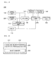
- FIG. 2 is a view showing a controlling unit 150 of the device 100 of displaying driving auxiliary information according to the exemplary embodiment of the present invention in detail.
- the controlling unit 150 of the device 100 of displaying driving auxiliary information may include a guide line extractor 151, a position calculator 152, and a determinator 153.
- the guide line extractor 151 serves to extract a guide line image according to the steering angle detected in the steering sensor 130 from the first storing unit 120.
- the guide line extracting unit 151 may search data stored in the first storing unit 120 to read data on the guide line image pre-stored with respect to the corresponding steering angle.
- the position calculator 152 serves to receive information on distance values from the plurality of distance sensors 140 to the object to calculate the position of the object.
- a distance from a left distance sensor 140 to the object is 1.5m
- a distance from a right distance sensor 140 to the object is 0.8m
- the determinator 153 compares the position of the object calculated in the position calculator 152 with the guide line image to determine whether or not the object is presented in the internal region of the guide line.
- warning information informing the existence of the object may be output together with the guide line image to the displaying unit 160.
- the guide line images stored in the first storing unit 120 may be stored as a color image. Therefore, the driver may more intuitively recognize the information on a distance.
- the color image is stored as a general bitmap image, a JPEG image, or the like
- data capacity thereof is several times larger than that of a black and white image. Therefore, in the case in which many guide line images are stored for each steering angle, an element having an excellent processing capability needs to be provided in order to rapidly and efficiently process the many guide line images.
- the guide line image may be encoded in an MRLC format including color information, a data width of a region configured of a corresponding color, and a blank width of a region in which an image is not present and then stored in the first storing unit 120.
- the device 100 of displaying driving auxiliary information may further include a decoder 180 decoding the guide line image encoded in the MRLC format and then store in the first storing unit 120 in a process of extracting the guide line image in the guide line extractor 151.
- a vertical synchronization unit 170 may be connected between the first storing unit 120 and an output terminal of the camera 110 to serve to synchronize a vertical synchronization signal.
- FIG. 3 is a view schematically showing a device 200 of displaying driving auxiliary information according to another exemplary embodiment of the present invention.
- the device 200 of displaying driving auxiliary information according to another exemplary embodiment of the present invention is different from the device 100 of displaying driving auxiliary information according to the exemplary embodiment of the present invention in that it further includes a second storing unit 220. Therefore, hereinafter, a description overlapped with that of the above-mentioned exemplary embodiment of the present invention will be omitted, and portions different from those of the above-mentioned exemplary embodiment of the present invention will be mainly described.
- the second storing unit 220 stores an object warning image according to a position of an object therein.
- the object warning image means an image to be displayed at a region corresponding to the position of the object among n regions when an inner portion of a guide line image divided for each steering angle is divided into the n region.
- the inner portion of the corresponding guide line image may be divided into 9 regions [(an upper region, a central region, and a lower region) ⁇ (a left region, a central region, a right region)] and the object warning images to be displayed at each region may be pre-stored in the second storing unit 220.
- FIG. 4 is a view showing a controlling unit 250 of the device 200 of displaying driving auxiliary information according to another embodiment of the present invention in detail.
- the controlling unit 250 of the device 200 of displaying driving auxiliary information may include a guide line extractor 251 and an object warning image extractor 252.
- the object warning image extractor 252 may calculate the position of the object using the distance values measured in the distance sensors 140 and extract an object warning image corresponding to the position of the object from the second storing unit 220 according to the calculation result.
- the image combiner 253 may combine the guide line image and the object warning image with each other to output the combined image to the displaying unit 160.
- the camera 110 may be further provided to output the image generated by combining the guide line image with the object warning image together with the real image photographed by the camera 110 to the displaying unit 160.
- the object warning image stored in the second storing unit 220 may also be encoded in the above-mentioned MRLC format.
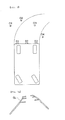
- FIG. 5 is a view describing a principle of sensing and displaying an object according to the related art
- FIG. 6 is a view describing a principle of sensing and displaying an object according to the exemplary embodiment of the present invention.
- distance information or a warning alarm for all of the objects 01, 02, 03, and 04 sensed in distance sensors S1, S2, and S3 has been output regardless of an expected driving trajectory of a vehicle.
- a separate warning is not output to objects 01, 02, and 04 positioned at an outer portion of a guide line image indicating an expected driving trajectory according to a steering angle of the vehicle, and a warning or distance information may be displayed for an object 03 positioned at an inner portion of the guide line image.
- a driver may obtain information more accurate as compared to the related art with respect to a situation of a direction in which he/she moves.
- FIGS. 7A to 7D are views schematically showing a screen displaying the driving auxiliary information according to the exemplary embodiment of the present invention, wherein FIG. 7A is a view showing a case in which an object is not present at an inner portion of a guide line GL, such that an object warning image is not displayed; FIG. 7B is a view showing a case in which the object is present at an upper end of the center of the inner portion of the guide line GL, such that the guide line GL and the object warning image AC1 are displayed; FIG. 7C is a view showing a case in which the object is present at a central end of the left of the inner portion of the guide line GL, such that the guide line GL and the object warning image AL2 are displayed; and FIG. 7D is a view showing a case in which the object is present at a lower end of the right of the inner portion of the guide line GL, such that the guide line GL and the object warning image AR3 are displayed.
- FIG. 7A is a view showing a case in
- FIGS. 7A to 7D in the case in which the object is not positioned at an internal region of the guide line GL, only a guide line GL image according to the steering angle is displayed as shown in FIG. 7A .
- the object warning images AC1, AL2, and AR3 in which the internal regions of the guide line is divided to approximately reflect the position of the object may be provided together with the guide line GL image, as shown in FIGS. 7B to 7C .
- FIG. 8 is a view schematically showing a method of displaying driving auxiliary information according to the exemplary embodiment of the present invention.
- the method of displaying driving auxiliary information according to the exemplary embodiment of the present invention is basically based on a state in which the guide line image is divided for each steering angle and pre-stored in a separate storing unit.
- a steering angle of a vehicle is detected (S110), and a distance of an object is measured (S111).
- a position of the object is calculated using distance values of the object measured in step S111 (S121).
- the position of the object may be directly displayed at the internal region of the guide line or whether or not the object is present or a distance up to the object may be displayed at a region having a position relationship unrelated to the guide line.
- FIG. 9 is a view schematically showing a modified example of FIG. 8 .
- a process of displaying an object present at the internal region of the guide line in the exemplary embodiment described with reference to FIG. 8 is further specified.
- the guide line image may be an image encoded in the MRLC format and then stored.
- the process of extracting the guide line image may include a process of decoding the guide line image encoded in the MRLC format.
- FIG. 10 is a view schematically showing a method of displaying driving auxiliary information according to another exemplary embodiment of the present invention.
- the method of displaying driving auxiliary information according to another exemplary embodiment of the present invention is different from the method displaying driving auxiliary information according to the exemplary embodiment of the present invention described with reference to FIGS. 8 and 9 in that it includes extracting (S123) an object warning image using a detected steering angle and a calculated position of an object.
- the method of displaying driving auxiliary information needs to be based on a state in which the object warning images to be displayed at each of the n divided regions of an inner portion of the guide line are pre-stored with respect to guide line images and each of the guide line images divided for each steering angle.
- the extracted guide line image and the object warning image may be combined with each other and then output (S140) or may be output together with a real image obtained through a separately provided camera.
- the present invention has been described in connection with what is presently considered to be practical exemplary embodiments. Although the exemplary embodiments of the present invention have been described, the present invention may be also used in various other combinations, modifications and environments. In other words, the present invention may be changed or modified within the range of concept of the invention disclosed in the specification, the range equivalent to the disclosure and/or the range of the technology or knowledge in the field to which the present invention pertains.
- the exemplary embodiments described above have been provided to explain the best state in carrying out the present invention. Therefore, they may be carried out in other states known to the field to which the present invention pertains in using other inventions such as the present invention and also be modified in various forms required in specific application fields and usages of the invention. Therefore, it is to be understood that the invention is not limited to the disclosed embodiments. It is to be understood that other embodiments are also included within the spirit and scope of the appended claims.
Landscapes
- Engineering & Computer Science (AREA)
- Mechanical Engineering (AREA)
- Transportation (AREA)
- Chemical & Material Sciences (AREA)
- Combustion & Propulsion (AREA)
- Automation & Control Theory (AREA)
- Radar, Positioning & Navigation (AREA)
- Remote Sensing (AREA)
- Human Computer Interaction (AREA)
- Multimedia (AREA)
- Traffic Control Systems (AREA)
- Closed-Circuit Television Systems (AREA)
Applications Claiming Priority (1)
| Application Number | Priority Date | Filing Date | Title |
|---|---|---|---|
| KR1020120057540A KR101387189B1 (ko) | 2012-05-30 | 2012-05-30 | 운행 보조정보 표시장치 및 운행 보조정보 표시방법 |
Publications (1)
| Publication Number | Publication Date |
|---|---|
| EP2669867A2 true EP2669867A2 (de) | 2013-12-04 |
Family
ID=48651941
Family Applications (1)
| Application Number | Title | Priority Date | Filing Date |
|---|---|---|---|
| EP13275121.5A Withdrawn EP2669867A2 (de) | 2012-05-30 | 2013-05-21 | Vorrichtung und Verfahren zur Anzeige von Fahrer-Hilfsinformationen |
Country Status (3)
| Country | Link |
|---|---|
| US (1) | US20130325313A1 (de) |
| EP (1) | EP2669867A2 (de) |
| KR (1) | KR101387189B1 (de) |
Cited By (1)
| Publication number | Priority date | Publication date | Assignee | Title |
|---|---|---|---|---|
| CN106314440A (zh) * | 2015-07-07 | 2017-01-11 | 大陆汽车电子(芜湖)有限公司 | 车距显示方法 |
Families Citing this family (10)
| Publication number | Priority date | Publication date | Assignee | Title |
|---|---|---|---|---|
| US9701245B2 (en) * | 2012-06-22 | 2017-07-11 | GM Global Technology Operations LLC | Alert systems and methods for a vehicle |
| US9153108B2 (en) | 2012-06-22 | 2015-10-06 | GM Global Technology Operations LLC | Alert systems and methods for a vehicle |
| US9493116B2 (en) | 2012-06-22 | 2016-11-15 | GM Global Technology Operations LLC | Alert systems and methods for a vehicle |
| US9349263B2 (en) | 2012-06-22 | 2016-05-24 | GM Global Technology Operations LLC | Alert systems and methods for a vehicle |
| US9266451B2 (en) | 2012-06-22 | 2016-02-23 | GM Global Technology Operations LLC | Alert systems and methods for a vehicle |
| US9123215B2 (en) | 2012-06-22 | 2015-09-01 | GM Global Technology Operations LLC | Alert systems and methods for a vehicle |
| KR101712399B1 (ko) * | 2014-11-25 | 2017-03-06 | 현대모비스 주식회사 | 차량의 후방 장애물 표시 방법 |
| KR101975154B1 (ko) * | 2015-09-28 | 2019-05-03 | 닛산 지도우샤 가부시키가이샤 | 차량용 표시 장치 및 차량용 표시 방법 |
| KR102192689B1 (ko) * | 2015-12-16 | 2020-12-17 | 현대자동차주식회사 | 차량 및 그 제어방법 |
| CN109508217B (zh) * | 2018-10-22 | 2022-03-08 | 郑州云海信息技术有限公司 | 一种数据处理方法、装置、设备及介质 |
Citations (2)
| Publication number | Priority date | Publication date | Assignee | Title |
|---|---|---|---|---|
| KR20100129965A (ko) | 2009-06-02 | 2010-12-10 | 삼성전기주식회사 | 자동차용 카메라 모듈 및 이를 이용한 주차 안내선 표시방법 |
| KR20110093726A (ko) | 2010-02-12 | 2011-08-18 | 로베르트 보쉬 게엠베하 | 자동차 후방 조망 및 주차 시스템을 위한 동적 범위 디스플레이 |
Family Cites Families (27)
| Publication number | Priority date | Publication date | Assignee | Title |
|---|---|---|---|---|
| US5400244A (en) * | 1991-06-25 | 1995-03-21 | Kabushiki Kaisha Toshiba | Running control system for mobile robot provided with multiple sensor information integration system |
| JP3351650B2 (ja) * | 1995-03-28 | 2002-12-03 | アルパイン株式会社 | ナビゲーション装置のデモンストレーション方法 |
| EP1324274A3 (de) * | 2001-12-28 | 2005-11-02 | Matsushita Electric Industrial Co., Ltd. | Speicherungssystem für Fahrzeuginformationen |
| JP2005182306A (ja) * | 2003-12-17 | 2005-07-07 | Denso Corp | 車両用表示装置 |
| JP2005236540A (ja) * | 2004-02-18 | 2005-09-02 | Matsushita Electric Ind Co Ltd | 車載カメラ装置 |
| EP1782228A1 (de) * | 2004-08-03 | 2007-05-09 | Silverbrook Research Pty. Ltd | Walk-up-druck |
| US20060190285A1 (en) * | 2004-11-04 | 2006-08-24 | Harris Trevor M | Method and apparatus for storage and distribution of real estate related data |
| JP4561479B2 (ja) * | 2005-05-26 | 2010-10-13 | アイシン・エィ・ダブリュ株式会社 | 駐車支援方法及び駐車支援装置 |
| US8519837B2 (en) * | 2005-09-08 | 2013-08-27 | Johnson Controls Gmbh | Driver assistance device for a vehicle and a method for visualizing the surroundings of a vehicle |
| US8982944B2 (en) * | 2005-10-12 | 2015-03-17 | Enforcement Video, Llc | Method and system for categorized event recording of images in multiple resolution levels |
| JP5309442B2 (ja) * | 2006-05-29 | 2013-10-09 | アイシン・エィ・ダブリュ株式会社 | 駐車支援方法及び駐車支援装置 |
| US9098939B2 (en) * | 2006-11-30 | 2015-08-04 | Lockheed Martin Corporation | System and method of generating light maps |
| JP2009012625A (ja) * | 2007-07-05 | 2009-01-22 | Panasonic Corp | 運転支援装置、運転支援方法及び運転支援プログラム |
| JP5160564B2 (ja) * | 2007-12-05 | 2013-03-13 | ボッシュ株式会社 | 車両情報表示装置 |
| JP5099451B2 (ja) * | 2008-12-01 | 2012-12-19 | アイシン精機株式会社 | 車両周辺確認装置 |
| US8520956B2 (en) * | 2009-06-09 | 2013-08-27 | Colorado State University Research Foundation | Optimized correlation filters for signal processing |
| TWI392366B (zh) * | 2009-12-31 | 2013-04-01 | Ind Tech Res Inst | 全周鳥瞰影像距離介面產生方法與系統 |
| US8531504B2 (en) * | 2010-06-11 | 2013-09-10 | Intel Corporation | System and method for 3D video stabilization by fusing orientation sensor readings and image alignment estimates |
| US8471691B2 (en) * | 2010-06-15 | 2013-06-25 | GM Global Technology Operations LLC | Portable vision system |
| JP5472026B2 (ja) * | 2010-06-29 | 2014-04-16 | トヨタ自動車株式会社 | 駐車支援装置 |
| JP5646923B2 (ja) * | 2010-09-03 | 2014-12-24 | 矢崎総業株式会社 | 車両用表示装置及び車両用表示システム |
| US8463073B2 (en) * | 2010-11-29 | 2013-06-11 | Microsoft Corporation | Robust recovery of transform invariant low-rank textures |
| JP5331146B2 (ja) * | 2011-03-22 | 2013-10-30 | 株式会社東芝 | 単眼ヘッドマウントディスプレイ |
| US8442307B1 (en) * | 2011-05-04 | 2013-05-14 | Google Inc. | Appearance augmented 3-D point clouds for trajectory and camera localization |
| US8692739B2 (en) * | 2011-09-22 | 2014-04-08 | GM Global Technology Operations LLC | Dynamic information presentation on full windshield head-up display |
| US20130083061A1 (en) * | 2011-09-30 | 2013-04-04 | GM Global Technology Operations LLC | Front- and rear- seat augmented reality vehicle game system to entertain & educate passengers |
| US9598836B2 (en) * | 2012-03-29 | 2017-03-21 | Harnischfeger Technologies, Inc. | Overhead view system for a shovel |
-
2012
- 2012-05-30 KR KR1020120057540A patent/KR101387189B1/ko not_active Expired - Fee Related
-
2013
- 2013-05-21 EP EP13275121.5A patent/EP2669867A2/de not_active Withdrawn
- 2013-05-29 US US13/905,068 patent/US20130325313A1/en not_active Abandoned
Patent Citations (2)
| Publication number | Priority date | Publication date | Assignee | Title |
|---|---|---|---|---|
| KR20100129965A (ko) | 2009-06-02 | 2010-12-10 | 삼성전기주식회사 | 자동차용 카메라 모듈 및 이를 이용한 주차 안내선 표시방법 |
| KR20110093726A (ko) | 2010-02-12 | 2011-08-18 | 로베르트 보쉬 게엠베하 | 자동차 후방 조망 및 주차 시스템을 위한 동적 범위 디스플레이 |
Cited By (1)
| Publication number | Priority date | Publication date | Assignee | Title |
|---|---|---|---|---|
| CN106314440A (zh) * | 2015-07-07 | 2017-01-11 | 大陆汽车电子(芜湖)有限公司 | 车距显示方法 |
Also Published As
| Publication number | Publication date |
|---|---|
| KR101387189B1 (ko) | 2014-04-29 |
| US20130325313A1 (en) | 2013-12-05 |
| KR20130134197A (ko) | 2013-12-10 |
Similar Documents
| Publication | Publication Date | Title |
|---|---|---|
| EP2669867A2 (de) | Vorrichtung und Verfahren zur Anzeige von Fahrer-Hilfsinformationen | |
| EP2080668B1 (de) | Lenkhilfevorrichtung, Verfahren und Computerprogrammprodukt für ein Fahrzeug | |
| EP2807642B1 (de) | Verfahren zum betreiben einer fahrerassistenzvorrichtung eines kraftfahrzeugs, fahrerassistenzvorrichtung und kraftfahrzeug | |
| JP4863791B2 (ja) | 車両周辺画像生成装置および画像切替方法 | |
| CN111201558B (zh) | 用于示出车辆的周围环境的方法 | |
| JP4815488B2 (ja) | 車両周辺監視装置 | |
| EP2352136A1 (de) | System zur überwachung der umgebung rund um ein fahrzeug | |
| US10186039B2 (en) | Apparatus and method for recognizing position of obstacle in vehicle | |
| US10384612B2 (en) | Dynamic camera view to aid with trailer attachment | |
| EP3150443A1 (de) | Anzeigevorrichtung für fahrzeuge und anzeigeverfahren für fahrzeuge | |
| JP4341705B2 (ja) | 車載画像処理装置 | |
| CN109415018B (zh) | 用于数字后视镜的方法和控制单元 | |
| JP5054612B2 (ja) | 接近物検出装置および接近物検出方法 | |
| JP4948338B2 (ja) | 車間距離計測装置 | |
| JP2008027309A (ja) | 衝突判定システム、及び衝突判定方法 | |
| WO2015186294A1 (ja) | 車載画像処理装置 | |
| JP2011227551A (ja) | 車両用蛇行運転検出装置 | |
| WO2017179206A1 (ja) | 駐車支援用表示制御装置および駐車支援用表示制御方法 | |
| JP2012208559A (ja) | 駐車支援装置 | |
| JP2007322357A (ja) | 距離測定プログラム、距離測定装置、距離測定方法 | |
| KR20180041525A (ko) | 차량의 물체 트래킹 시스템 및 그 제어 방법 | |
| JP2010056975A (ja) | リアカメラによる物体検知方式 | |
| JP2004364112A (ja) | 車両周辺表示装置 | |
| JP2009230229A (ja) | 物体検出装置 | |
| JP5132796B2 (ja) | 車両周辺画像生成装置および画像切替方法 |
Legal Events
| Date | Code | Title | Description |
|---|---|---|---|
| PUAI | Public reference made under article 153(3) epc to a published international application that has entered the european phase |
Free format text: ORIGINAL CODE: 0009012 |
|
| 17P | Request for examination filed |
Effective date: 20130521 |
|
| AK | Designated contracting states |
Kind code of ref document: A2 Designated state(s): AL AT BE BG CH CY CZ DE DK EE ES FI FR GB GR HR HU IE IS IT LI LT LU LV MC MK MT NL NO PL PT RO RS SE SI SK SM TR |
|
| AX | Request for extension of the european patent |
Extension state: BA ME |
|
| STAA | Information on the status of an ep patent application or granted ep patent |
Free format text: STATUS: THE APPLICATION HAS BEEN WITHDRAWN |
|
| 18W | Application withdrawn |
Effective date: 20160929 |