EP2669571A1 - Lighting module and corresponding integrated lighting system - Google Patents
Lighting module and corresponding integrated lighting system Download PDFInfo
- Publication number
- EP2669571A1 EP2669571A1 EP13169795.5A EP13169795A EP2669571A1 EP 2669571 A1 EP2669571 A1 EP 2669571A1 EP 13169795 A EP13169795 A EP 13169795A EP 2669571 A1 EP2669571 A1 EP 2669571A1
- Authority
- EP
- European Patent Office
- Prior art keywords
- light
- lighting module
- support
- base structure
- light point
- Prior art date
- Legal status (The legal status is an assumption and is not a legal conclusion. Google has not performed a legal analysis and makes no representation as to the accuracy of the status listed.)
- Withdrawn
Links
Images


Classifications
-
- F—MECHANICAL ENGINEERING; LIGHTING; HEATING; WEAPONS; BLASTING
- F21—LIGHTING
- F21V—FUNCTIONAL FEATURES OR DETAILS OF LIGHTING DEVICES OR SYSTEMS THEREOF; STRUCTURAL COMBINATIONS OF LIGHTING DEVICES WITH OTHER ARTICLES, NOT OTHERWISE PROVIDED FOR
- F21V5/00—Refractors for light sources
- F21V5/08—Refractors for light sources producing an asymmetric light distribution
-
- F—MECHANICAL ENGINEERING; LIGHTING; HEATING; WEAPONS; BLASTING
- F21—LIGHTING
- F21V—FUNCTIONAL FEATURES OR DETAILS OF LIGHTING DEVICES OR SYSTEMS THEREOF; STRUCTURAL COMBINATIONS OF LIGHTING DEVICES WITH OTHER ARTICLES, NOT OTHERWISE PROVIDED FOR
- F21V13/00—Producing particular characteristics or distribution of the light emitted by means of a combination of elements specified in two or more of main groups F21V1/00 - F21V11/00
- F21V13/02—Combinations of only two kinds of elements
- F21V13/04—Combinations of only two kinds of elements the elements being reflectors and refractors
-
- F—MECHANICAL ENGINEERING; LIGHTING; HEATING; WEAPONS; BLASTING
- F21—LIGHTING
- F21V—FUNCTIONAL FEATURES OR DETAILS OF LIGHTING DEVICES OR SYSTEMS THEREOF; STRUCTURAL COMBINATIONS OF LIGHTING DEVICES WITH OTHER ARTICLES, NOT OTHERWISE PROVIDED FOR
- F21V19/00—Fastening of light sources or lamp holders
- F21V19/02—Fastening of light sources or lamp holders with provision for adjustment, e.g. for focusing
-
- H—ELECTRICITY
- H05—ELECTRIC TECHNIQUES NOT OTHERWISE PROVIDED FOR
- H05K—PRINTED CIRCUITS; CASINGS OR CONSTRUCTIONAL DETAILS OF ELECTRIC APPARATUS; MANUFACTURE OF ASSEMBLAGES OF ELECTRICAL COMPONENTS
- H05K1/00—Printed circuits
- H05K1/02—Details
- H05K1/0286—Programmable, customizable or modifiable circuits
- H05K1/0295—Programmable, customizable or modifiable circuits adapted for choosing between different types or different locations of mounted components
-
- H—ELECTRICITY
- H05—ELECTRIC TECHNIQUES NOT OTHERWISE PROVIDED FOR
- H05K—PRINTED CIRCUITS; CASINGS OR CONSTRUCTIONAL DETAILS OF ELECTRIC APPARATUS; MANUFACTURE OF ASSEMBLAGES OF ELECTRICAL COMPONENTS
- H05K1/00—Printed circuits
- H05K1/02—Details
- H05K1/14—Structural association of two or more printed circuits
- H05K1/142—Arrangements of planar printed circuit boards in the same plane, e.g. auxiliary printed circuit insert mounted in a main printed circuit
-
- F—MECHANICAL ENGINEERING; LIGHTING; HEATING; WEAPONS; BLASTING
- F21—LIGHTING
- F21Y—INDEXING SCHEME ASSOCIATED WITH SUBCLASSES F21K, F21L, F21S and F21V, RELATING TO THE FORM OR THE KIND OF THE LIGHT SOURCES OR OF THE COLOUR OF THE LIGHT EMITTED
- F21Y2115/00—Light-generating elements of semiconductor light sources
- F21Y2115/10—Light-emitting diodes [LED]
-
- H—ELECTRICITY
- H05—ELECTRIC TECHNIQUES NOT OTHERWISE PROVIDED FOR
- H05K—PRINTED CIRCUITS; CASINGS OR CONSTRUCTIONAL DETAILS OF ELECTRIC APPARATUS; MANUFACTURE OF ASSEMBLAGES OF ELECTRICAL COMPONENTS
- H05K1/00—Printed circuits
- H05K1/02—Details
- H05K1/0274—Optical details, e.g. printed circuits comprising integral optical means
-
- H—ELECTRICITY
- H05—ELECTRIC TECHNIQUES NOT OTHERWISE PROVIDED FOR
- H05K—PRINTED CIRCUITS; CASINGS OR CONSTRUCTIONAL DETAILS OF ELECTRIC APPARATUS; MANUFACTURE OF ASSEMBLAGES OF ELECTRICAL COMPONENTS
- H05K2201/00—Indexing scheme relating to printed circuits covered by H05K1/00
- H05K2201/04—Assemblies of printed circuits
- H05K2201/049—PCB for one component, e.g. for mounting onto mother PCB
-
- H—ELECTRICITY
- H05—ELECTRIC TECHNIQUES NOT OTHERWISE PROVIDED FOR
- H05K—PRINTED CIRCUITS; CASINGS OR CONSTRUCTIONAL DETAILS OF ELECTRIC APPARATUS; MANUFACTURE OF ASSEMBLAGES OF ELECTRICAL COMPONENTS
- H05K2201/00—Indexing scheme relating to printed circuits covered by H05K1/00
- H05K2201/10—Details of components or other objects attached to or integrated in a printed circuit board
- H05K2201/10007—Types of components
- H05K2201/10106—Light emitting diode [LED]
Definitions
- the description relates to lighting modules.
- lighting modules comprising at least one light source, such as one or more LEDs (Light Emitting Diodes) or other solid state lighting means mounted on a printed circuit board (PCB).
- LEDs Light Emitting Diodes
- PCB printed circuit board
- a lighting module further comprises optical means such as lenses or reflectors configured to determine the distribution of the light emitted by the light sources.
- the distribution of the emitted light is therefore typically predetermined and is dependent on the specific optical means used.
- the object of the invention is to provide solutions which enable the distribution of the light emitted by a lighting module to be varied without the need to change components of the lighting module.
- this object is achieved by means of a lighting module having the characteristics claimed in the claims below.
- the invention also relates to a corresponding integrated lighting device.
- a lighting module comprising a base structure and a plurality of light points which generate light radiation.
- these light points are coupled to the base structure, which may, for example, be a printed circuit board.
- the base structure allows the light point to be coupled with different orientations. Consequently, the same light point can have different orientations with respect to the base structure, and therefore, because of the asymmetry in the radiation pattern of the light point, the radiation pattern of the whole lighting module can be modified.
- the light point includes a light source, such as an LED, coupled rigidly to a support.
- the light point further comprises optical means, such as a lens or a reflector, which have a radiation pattern with rotational asymmetry. The rotational asymmetry of the light point is therefore created by these optical means.
- the orientation of the light point can be set in a continuous manner; in other words, the light point can be rotatable with respect to the base structure.
- the support of the light point has a circular cross section
- the base structure comprises at least one cavity which has a shape substantially complementary to the shape of the support of the light point.
- the electrical connection between the light point and the base structure is provided by means of a slidable connection.
- mechanical attachment systems such as clips or pins
- an embodiment in this description is intended to indicate that a particular configuration, structure or characteristic described in relation to the embodiment is included in at least one embodiment. Therefore, phrases such as “in one embodiment”, which may be present in various parts of this description, do not necessarily refer to the same embodiment. Furthermore, specific formations, structures or characteristics may be combined in a suitable way in one or more embodiments.
- the present description can be used to produce solutions in which the distribution of the emitted light is modifiable.
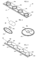
- Figure 1 shows a possible embodiment of a lighting module 20 of this type, which comprises a plurality of light points 24.
- the lighting module 20 comprises a base structure 22 and four light points 24a, 24b, 24c and 24d.
- one or more of these light points 24 can be rotated or pivoted with respect to the base structure 22.
- these rotatable light points 24 have a radiation pattern with rotational asymmetry.
- the orientation of the radiation profile of a light point 24 can therefore be modified by rotating the respective light point 24.
- a change in the radiation pattern of a light point 24 also affects the radiation pattern of the whole lighting module 20; in other words, the radiation pattern of the whole lighting module 20 can be modified by controlling the orientation of the light points 24.
- Figures 2a and 2b show a possible embodiment of a light point 24.
- the light point 24 comprises a light source 246, such as an LED, which is mounted on a support 242.
- the support 242 is a printed circuit board which comprises electrical tracks 244 for powering the light source 246.
- this printed circuit board 242 can be made of FR4 or could also have a metal core.
- the rotational asymmetry in the radiation pattern of the light point 24 is created by optical means 248 which are mounted in the path of the light emitted by the source 246.
- these optical means 248 have rotational asymmetry.
- lenses or reflectors having different radiation patterns in two transverse directions can be used for this purpose.
- the light source 246 and the optical means, in other words the lens 248, are coupled rigidly to the support 242.
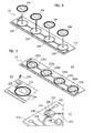
- Figure 3 shows a possible embodiment of the base structure 22.
- the base structure 22 comprises a printed circuit board 222.
- this printed circuit board 222 comprises electrical tracks 224 for powering the light sources 24.
- these electrical tracks 224 are connected to two contacts 226 which, in turn, can be used for connection to an electronic converter.
- the base structure 22 also comprises means for supporting the light points 24. These support means enable a light point 24 to be coupled to the base structure 22 in different orientations.
- the printed circuit board 222 comprises, for each light point 24, a cavity 228 which has a cross section substantially complementary to the cross section of the support 242 of the light point 24.
- the support 242 is disk-shaped; in other words, it has a circular cross section, and therefore the cavities 228 also have circular cross sections. These cavities 228 are preferably equidistant from each other.
- the printed circuit board 222 is fastened to the casing of the lighting module 20 or to another supporting structure.
- the printed circuit board 222 could be mounted on a heat sink.
- the printed circuit board 222 could be mounted together with a respective electronic converter within an integrated lighting system.
- the light points 24 are inserted into these cavities 228. Consequently, in the embodiment considered here, the support 242 of a light point 24 can be rotated directly within the respective cavity 228.
- supports 242 and cavities 228 of other shapes can also be used.
- the supports 242 and the cavities 228 have cross sections in the form of a regular polygon.
- the light point 24 is not directly rotatable within the cavity 228, but the light point 24 can be removed from the cavity 228 and can be reinserted with a different orientation.
- a light point 24 can be coupled to the base structure 22 with different orientations.
- the light point 24 is fastened by suitable fastening means to the base structure 22; in other words, these fastening means can be used to lock the movement, or the orientation, of a light point 24.
- Figures 5a to 5c show an embodiment in which the support 242 is fastened to the printed circuit board 222 by means of at least one screw 230.
- this screw 230 interacts with a corresponding opening 234 in the base structure 22, in other words in the printed circuit board 222, and presses a locking element 232 against the support 242 of the light point 24.
- the locking element 232 comprises a through hole 236 for this purpose.
- the printed circuit board 222 can be mounted on a support structure, such as a cooling body.
- the screw or screws 230 can be used to fasten the printed circuit board 222 simultaneously to this support structure.
- the locking element 232 has a dual function.
- the locking element 232 fastens the light point to the base structure and locks the movement of the light point 24.
- the locking element 232 is configured to provide the electrical connection between the base structure 22 and the light point 24, in other words between the tracks 224 of the printed circuit board 222 and the tracks 244 of the support 242.
- the locking element 232 comprises a metal element or is made at least partially of a metallic material.
- the locking element is made in the form of a rectangular plastic parallelepiped and comprises within itself a metal link, such as a bent metal strip.
- the electrical tracks 244 are preferably brought to the edge of the support 242 and enable the light point 24 to be electrically connected in different orientations; in other words, the electrical tracks 244 at least partially follow the edge of the support 242.
- the electrical tracks 244 can follow the whole edge of the support 242, or can follow a circumferential line within the support 242. Consequently, in the embodiment considered here, the tracks 244 and the locking element 232 form a sliding contact. For this purpose, at least a part of the tracks 244 is exposed; in other words it is not covered by the solder mask or other insulating layers.
- the locking element 232 may also comprise a plurality of metal elements 238, in order to provide a plurality of electrical contacts between the printed circuit board 222 and the light point 24.
- the support 242 is fastened to the base structure 22 by means of two locking elements 232a and 232b, and each locking element 232 forms only one electrical contact.
- the locking elements 232a and 232b are preferably arranged on opposite sides of the support 242.
- this type of fastening may be advantageous in the case in which the light points 24 are arranged in line and are electrically connected in series, this being a typical arrangement for what are known as linear LED modules.
- each light point 24 can comprise optical means 248, such as a lens or a reflector, which have rotational asymmetry.
- the rotational asymmetry relates to rotation about an axis which is perpendicular to the support 242.
- this rotational asymmetry may be created by the shape of the lens and/or by the material used.
- Figures 6a and 6c show an optical lens 248 which can be used for this purpose.
- the lens 248 has a structure in the shape of a peanut, in other words a shape substantially formed by the intersection of two spheres.
- Figure 6c shows the radiation pattern of the lens 248 in two orthogonal planes.
- Figure 6c shows the radiation pattern for these two planes, which in both cases depend on the angle of view with reference to the respective plane.
- Figures 7a to 7f show some examples of configurations that can be obtained with the lighting module 20 described above.
- all the light points 24 are in the initial position; in other words, the angle of rotation for all the light points 24 is 0°.
- Figures 7b , 7c and 7d show embodiments in which the light points 24 have an angle of rotation of 90°, 180° and 270° respectively.
- the radiation pattern of the lighting module 20 shown in Figure 7c will be different from the radiation pattern of the lighting module 20 shown in Figure 7a , and the same is also true of the radiation patterns of the configurations shown in Figures 7b and 7d .
- the angle of rotation may be set in a continuous manner for circular supports 242.
- Figure 7e shows an embodiment in which all the light points 24 have an angle of rotation of 135°.
- each light point 24 it is also possible for each light point 24 to have a different angle of rotation; in other words, the angle of rotation of each light point 24 can be set independently.
- Figure 7f shows an embodiment in which the first and third light points 24a and 24c have an angle of rotation of 0° and the second and fourth light points 24b and 24d have an angle of rotation of 180°.
- solutions using a light point 24 with a circular support 242 allow the orientation of the light point 24 to be changed in a continuous manner without the need to detach components of the lighting module 20.
- solutions described here can be used for any arrangement of light points 24.
- the solutions described here can be used both in linear LED modules and in LED arrays.
Landscapes
- Engineering & Computer Science (AREA)
- General Engineering & Computer Science (AREA)
- Microelectronics & Electronic Packaging (AREA)
- Fastening Of Light Sources Or Lamp Holders (AREA)
- Non-Portable Lighting Devices Or Systems Thereof (AREA)
Applications Claiming Priority (1)
| Application Number | Priority Date | Filing Date | Title |
|---|---|---|---|
| ITTO20120482 | 2012-06-01 |
Publications (1)
| Publication Number | Publication Date |
|---|---|
| EP2669571A1 true EP2669571A1 (en) | 2013-12-04 |
Family
ID=46262259
Family Applications (1)
| Application Number | Title | Priority Date | Filing Date |
|---|---|---|---|
| EP13169795.5A Withdrawn EP2669571A1 (en) | 2012-06-01 | 2013-05-29 | Lighting module and corresponding integrated lighting system |
Country Status (3)
| Country | Link |
|---|---|
| US (1) | US9086210B2 (zh) |
| EP (1) | EP2669571A1 (zh) |
| CN (1) | CN103527946B (zh) |
Families Citing this family (2)
| Publication number | Priority date | Publication date | Assignee | Title |
|---|---|---|---|---|
| USD858809S1 (en) * | 2017-06-15 | 2019-09-03 | Robby Hoon Kang | Rhombus LED module casing |
| EP3441665B1 (en) * | 2017-08-08 | 2022-05-11 | Marelli Automotive Lighting Italy S.p.A. | Rotating lighting module for vehicles and associated lighting device for vehicles |
Citations (2)
| Publication number | Priority date | Publication date | Assignee | Title |
|---|---|---|---|---|
| JP2008103300A (ja) * | 2006-09-21 | 2008-05-01 | Toshiba Lighting & Technology Corp | Ledモジュール及び照明器具 |
| WO2011149237A2 (ko) * | 2010-05-24 | 2011-12-01 | 주식회사 아모럭스 | 비대칭 배광곡선을 조정하는 led조립체와 그를 이용한 착탈식 led조립블록 및 착탈식 블록 조립구조를 가지는 led조명장치 |
Family Cites Families (8)
| Publication number | Priority date | Publication date | Assignee | Title |
|---|---|---|---|---|
| US6837605B2 (en) * | 2001-11-28 | 2005-01-04 | Osram Opto Semiconductors Gmbh | Led illumination system |
| KR100852579B1 (ko) * | 2003-03-31 | 2008-08-14 | 샤프 가부시키가이샤 | 면 조명 장치 및 그것을 이용한 액정 표시 장치 |
| US20060012977A1 (en) * | 2004-07-02 | 2006-01-19 | Litesnow Llc | Slatwall lighting system |
| CA2641832C (en) * | 2006-02-27 | 2012-10-23 | Illumination Management Solutions Inc. | An improved led device for wide beam generation |
| US7618163B2 (en) * | 2007-04-02 | 2009-11-17 | Ruud Lighting, Inc. | Light-directing LED apparatus |
| EP2607169B1 (en) * | 2007-05-21 | 2021-07-07 | Signify Holding B.V. | An improved LED device for wide beam generation and method of making the same |
| CN101487579B (zh) * | 2008-01-17 | 2010-06-02 | 宁波燎原灯具股份有限公司 | 适用于led路灯的透镜系统 |
| DE102008007723A1 (de) * | 2008-02-06 | 2009-08-20 | Osram Gesellschaft mit beschränkter Haftung | Beleuchtungsmodul, Leuchte und Verfahren zur Beleuchtung |
-
2013
- 2013-05-29 EP EP13169795.5A patent/EP2669571A1/en not_active Withdrawn
- 2013-05-31 US US13/906,452 patent/US9086210B2/en not_active Expired - Fee Related
- 2013-06-03 CN CN201310218062.5A patent/CN103527946B/zh not_active Expired - Fee Related
Patent Citations (2)
| Publication number | Priority date | Publication date | Assignee | Title |
|---|---|---|---|---|
| JP2008103300A (ja) * | 2006-09-21 | 2008-05-01 | Toshiba Lighting & Technology Corp | Ledモジュール及び照明器具 |
| WO2011149237A2 (ko) * | 2010-05-24 | 2011-12-01 | 주식회사 아모럭스 | 비대칭 배광곡선을 조정하는 led조립체와 그를 이용한 착탈식 led조립블록 및 착탈식 블록 조립구조를 가지는 led조명장치 |
Also Published As
| Publication number | Publication date |
|---|---|
| CN103527946B (zh) | 2017-10-24 |
| CN103527946A (zh) | 2014-01-22 |
| US20130335964A1 (en) | 2013-12-19 |
| US9086210B2 (en) | 2015-07-21 |
Similar Documents
| Publication | Publication Date | Title |
|---|---|---|
| JP5968916B2 (ja) | Ledベースのモジュールアセンブリ | |
| US9325134B2 (en) | Pivot connector, power input assembly, electrical connector apparatus, and method of pivoting electrically connecting apparatus | |
| JP5615789B2 (ja) | 発光装置 | |
| US9964260B2 (en) | LED lighting device with improved light distribution | |
| KR101038255B1 (ko) | Led모듈이 다각화된 조명장치 | |
| EP2713098B1 (en) | Lighting device | |
| MX2015002314A (es) | Modulo de iluminacion para un vehiculo motorizado. | |
| JP6592636B2 (ja) | コンフィギュラブルな光学モジュール及びledアセンブリ | |
| US9086210B2 (en) | Lighting module and corresponding integrated lighting device | |
| EP3877696B1 (en) | A lighting system | |
| EP2722589B1 (en) | Angled emitter channel letter lighting | |
| JP5747009B2 (ja) | Led照明装置 | |
| KR20100044632A (ko) | 엘이디 조명장치용 회로모듈 및 그를 포함하는 엘이디 조명장치 | |
| JP5515005B2 (ja) | 照明装置 | |
| JP6755548B2 (ja) | 照明装置 | |
| JP2013225455A (ja) | 照明装置 | |
| JP7489997B2 (ja) | 自動車両の照明装置 | |
| KR20110024195A (ko) | 표시 장치 | |
| KR102113830B1 (ko) | 조명 장치 | |
| KR20200045072A (ko) | 광고용 led 모듈 | |
| KR20140136658A (ko) | 조명장치 | |
| KR20150059276A (ko) | 조명장치 |
Legal Events
| Date | Code | Title | Description |
|---|---|---|---|
| PUAI | Public reference made under article 153(3) epc to a published international application that has entered the european phase |
Free format text: ORIGINAL CODE: 0009012 |
|
| AK | Designated contracting states |
Kind code of ref document: A1 Designated state(s): AL AT BE BG CH CY CZ DE DK EE ES FI FR GB GR HR HU IE IS IT LI LT LU LV MC MK MT NL NO PL PT RO RS SE SI SK SM TR |
|
| AX | Request for extension of the european patent |
Extension state: BA ME |
|
| 17P | Request for examination filed |
Effective date: 20140604 |
|
| RBV | Designated contracting states (corrected) |
Designated state(s): AL AT BE BG CH CY CZ DE DK EE ES FI FR GB GR HR HU IE IS IT LI LT LU LV MC MK MT NL NO PL PT RO RS SE SI SK SM TR |
|
| 17Q | First examination report despatched |
Effective date: 20141028 |
|
| GRAP | Despatch of communication of intention to grant a patent |
Free format text: ORIGINAL CODE: EPIDOSNIGR1 |
|
| INTG | Intention to grant announced |
Effective date: 20150610 |
|
| RIC1 | Information provided on ipc code assigned before grant |
Ipc: F21Y 101/02 20060101ALN20150601BHEP Ipc: H05K 3/32 20060101ALI20150601BHEP Ipc: F21V 5/08 20060101AFI20150601BHEP Ipc: F21V 19/02 20060101ALI20150601BHEP Ipc: H05K 1/02 20060101ALI20150601BHEP |
|
| STAA | Information on the status of an ep patent application or granted ep patent |
Free format text: STATUS: THE APPLICATION IS DEEMED TO BE WITHDRAWN |
|
| 18D | Application deemed to be withdrawn |
Effective date: 20151021 |