EP2669539A1 - Shell type needle bearing and joint cross type universal joint - Google Patents
Shell type needle bearing and joint cross type universal joint Download PDFInfo
- Publication number
- EP2669539A1 EP2669539A1 EP12739717.2A EP12739717A EP2669539A1 EP 2669539 A1 EP2669539 A1 EP 2669539A1 EP 12739717 A EP12739717 A EP 12739717A EP 2669539 A1 EP2669539 A1 EP 2669539A1
- Authority
- EP
- European Patent Office
- Prior art keywords
- shell
- section
- type
- outer ring
- seal
- Prior art date
- Legal status (The legal status is an assumption and is not a legal conclusion. Google has not performed a legal analysis and makes no representation as to the accuracy of the status listed.)
- Granted
Links
Images



Classifications
-
- F—MECHANICAL ENGINEERING; LIGHTING; HEATING; WEAPONS; BLASTING
- F16—ENGINEERING ELEMENTS AND UNITS; GENERAL MEASURES FOR PRODUCING AND MAINTAINING EFFECTIVE FUNCTIONING OF MACHINES OR INSTALLATIONS; THERMAL INSULATION IN GENERAL
- F16D—COUPLINGS FOR TRANSMITTING ROTATION; CLUTCHES; BRAKES
- F16D3/00—Yielding couplings, i.e. with means permitting movement between the connected parts during the drive
- F16D3/16—Universal joints in which flexibility is produced by means of pivots or sliding or rolling connecting parts
- F16D3/26—Hooke's joints or other joints with an equivalent intermediate member to which each coupling part is pivotally or slidably connected
- F16D3/38—Hooke's joints or other joints with an equivalent intermediate member to which each coupling part is pivotally or slidably connected with a single intermediate member with trunnions or bearings arranged on two axes perpendicular to one another
- F16D3/40—Hooke's joints or other joints with an equivalent intermediate member to which each coupling part is pivotally or slidably connected with a single intermediate member with trunnions or bearings arranged on two axes perpendicular to one another with intermediate member provided with two pairs of outwardly-directed trunnions on intersecting axes
- F16D3/41—Hooke's joints or other joints with an equivalent intermediate member to which each coupling part is pivotally or slidably connected with a single intermediate member with trunnions or bearings arranged on two axes perpendicular to one another with intermediate member provided with two pairs of outwardly-directed trunnions on intersecting axes with ball or roller bearings
-
- F—MECHANICAL ENGINEERING; LIGHTING; HEATING; WEAPONS; BLASTING
- F16—ENGINEERING ELEMENTS AND UNITS; GENERAL MEASURES FOR PRODUCING AND MAINTAINING EFFECTIVE FUNCTIONING OF MACHINES OR INSTALLATIONS; THERMAL INSULATION IN GENERAL
- F16C—SHAFTS; FLEXIBLE SHAFTS; ELEMENTS OR CRANKSHAFT MECHANISMS; ROTARY BODIES OTHER THAN GEARING ELEMENTS; BEARINGS
- F16C19/00—Bearings with rolling contact, for exclusively rotary movement
- F16C19/22—Bearings with rolling contact, for exclusively rotary movement with bearing rollers essentially of the same size in one or more circular rows, e.g. needle bearings
- F16C19/225—Details of the ribs supporting the end of the rollers
-
- F—MECHANICAL ENGINEERING; LIGHTING; HEATING; WEAPONS; BLASTING
- F16—ENGINEERING ELEMENTS AND UNITS; GENERAL MEASURES FOR PRODUCING AND MAINTAINING EFFECTIVE FUNCTIONING OF MACHINES OR INSTALLATIONS; THERMAL INSULATION IN GENERAL
- F16C—SHAFTS; FLEXIBLE SHAFTS; ELEMENTS OR CRANKSHAFT MECHANISMS; ROTARY BODIES OTHER THAN GEARING ELEMENTS; BEARINGS
- F16C19/00—Bearings with rolling contact, for exclusively rotary movement
- F16C19/22—Bearings with rolling contact, for exclusively rotary movement with bearing rollers essentially of the same size in one or more circular rows, e.g. needle bearings
- F16C19/24—Bearings with rolling contact, for exclusively rotary movement with bearing rollers essentially of the same size in one or more circular rows, e.g. needle bearings for radial load mainly
- F16C19/26—Bearings with rolling contact, for exclusively rotary movement with bearing rollers essentially of the same size in one or more circular rows, e.g. needle bearings for radial load mainly with a single row of rollers
-
- F—MECHANICAL ENGINEERING; LIGHTING; HEATING; WEAPONS; BLASTING
- F16—ENGINEERING ELEMENTS AND UNITS; GENERAL MEASURES FOR PRODUCING AND MAINTAINING EFFECTIVE FUNCTIONING OF MACHINES OR INSTALLATIONS; THERMAL INSULATION IN GENERAL
- F16C—SHAFTS; FLEXIBLE SHAFTS; ELEMENTS OR CRANKSHAFT MECHANISMS; ROTARY BODIES OTHER THAN GEARING ELEMENTS; BEARINGS
- F16C19/00—Bearings with rolling contact, for exclusively rotary movement
- F16C19/22—Bearings with rolling contact, for exclusively rotary movement with bearing rollers essentially of the same size in one or more circular rows, e.g. needle bearings
- F16C19/44—Needle bearings
-
- F—MECHANICAL ENGINEERING; LIGHTING; HEATING; WEAPONS; BLASTING
- F16—ENGINEERING ELEMENTS AND UNITS; GENERAL MEASURES FOR PRODUCING AND MAINTAINING EFFECTIVE FUNCTIONING OF MACHINES OR INSTALLATIONS; THERMAL INSULATION IN GENERAL
- F16C—SHAFTS; FLEXIBLE SHAFTS; ELEMENTS OR CRANKSHAFT MECHANISMS; ROTARY BODIES OTHER THAN GEARING ELEMENTS; BEARINGS
- F16C19/00—Bearings with rolling contact, for exclusively rotary movement
- F16C19/52—Bearings with rolling contact, for exclusively rotary movement with devices affected by abnormal or undesired conditions
-
- F—MECHANICAL ENGINEERING; LIGHTING; HEATING; WEAPONS; BLASTING
- F16—ENGINEERING ELEMENTS AND UNITS; GENERAL MEASURES FOR PRODUCING AND MAINTAINING EFFECTIVE FUNCTIONING OF MACHINES OR INSTALLATIONS; THERMAL INSULATION IN GENERAL
- F16C—SHAFTS; FLEXIBLE SHAFTS; ELEMENTS OR CRANKSHAFT MECHANISMS; ROTARY BODIES OTHER THAN GEARING ELEMENTS; BEARINGS
- F16C21/00—Combinations of sliding-contact bearings with ball or roller bearings, for exclusively rotary movement
- F16C21/005—Combinations of sliding-contact bearings with ball or roller bearings, for exclusively rotary movement the external zone of a bearing with rolling members, e.g. needles, being cup-shaped, with or without a separate thrust-bearing disc or ring, e.g. for universal joints
-
- F—MECHANICAL ENGINEERING; LIGHTING; HEATING; WEAPONS; BLASTING
- F16—ENGINEERING ELEMENTS AND UNITS; GENERAL MEASURES FOR PRODUCING AND MAINTAINING EFFECTIVE FUNCTIONING OF MACHINES OR INSTALLATIONS; THERMAL INSULATION IN GENERAL
- F16C—SHAFTS; FLEXIBLE SHAFTS; ELEMENTS OR CRANKSHAFT MECHANISMS; ROTARY BODIES OTHER THAN GEARING ELEMENTS; BEARINGS
- F16C33/00—Parts of bearings; Special methods for making bearings or parts thereof
- F16C33/30—Parts of ball or roller bearings
- F16C33/58—Raceways; Race rings
-
- F—MECHANICAL ENGINEERING; LIGHTING; HEATING; WEAPONS; BLASTING
- F16—ENGINEERING ELEMENTS AND UNITS; GENERAL MEASURES FOR PRODUCING AND MAINTAINING EFFECTIVE FUNCTIONING OF MACHINES OR INSTALLATIONS; THERMAL INSULATION IN GENERAL
- F16C—SHAFTS; FLEXIBLE SHAFTS; ELEMENTS OR CRANKSHAFT MECHANISMS; ROTARY BODIES OTHER THAN GEARING ELEMENTS; BEARINGS
- F16C33/00—Parts of bearings; Special methods for making bearings or parts thereof
- F16C33/30—Parts of ball or roller bearings
- F16C33/58—Raceways; Race rings
- F16C33/583—Details of specific parts of races
- F16C33/586—Details of specific parts of races outside the space between the races, e.g. end faces or bore of inner ring
-
- F—MECHANICAL ENGINEERING; LIGHTING; HEATING; WEAPONS; BLASTING
- F16—ENGINEERING ELEMENTS AND UNITS; GENERAL MEASURES FOR PRODUCING AND MAINTAINING EFFECTIVE FUNCTIONING OF MACHINES OR INSTALLATIONS; THERMAL INSULATION IN GENERAL
- F16C—SHAFTS; FLEXIBLE SHAFTS; ELEMENTS OR CRANKSHAFT MECHANISMS; ROTARY BODIES OTHER THAN GEARING ELEMENTS; BEARINGS
- F16C33/00—Parts of bearings; Special methods for making bearings or parts thereof
- F16C33/30—Parts of ball or roller bearings
- F16C33/58—Raceways; Race rings
- F16C33/588—Races of sheet metal
-
- F—MECHANICAL ENGINEERING; LIGHTING; HEATING; WEAPONS; BLASTING
- F16—ENGINEERING ELEMENTS AND UNITS; GENERAL MEASURES FOR PRODUCING AND MAINTAINING EFFECTIVE FUNCTIONING OF MACHINES OR INSTALLATIONS; THERMAL INSULATION IN GENERAL
- F16C—SHAFTS; FLEXIBLE SHAFTS; ELEMENTS OR CRANKSHAFT MECHANISMS; ROTARY BODIES OTHER THAN GEARING ELEMENTS; BEARINGS
- F16C33/00—Parts of bearings; Special methods for making bearings or parts thereof
- F16C33/30—Parts of ball or roller bearings
- F16C33/58—Raceways; Race rings
- F16C33/62—Selection of substances
-
- F—MECHANICAL ENGINEERING; LIGHTING; HEATING; WEAPONS; BLASTING
- F16—ENGINEERING ELEMENTS AND UNITS; GENERAL MEASURES FOR PRODUCING AND MAINTAINING EFFECTIVE FUNCTIONING OF MACHINES OR INSTALLATIONS; THERMAL INSULATION IN GENERAL
- F16C—SHAFTS; FLEXIBLE SHAFTS; ELEMENTS OR CRANKSHAFT MECHANISMS; ROTARY BODIES OTHER THAN GEARING ELEMENTS; BEARINGS
- F16C33/00—Parts of bearings; Special methods for making bearings or parts thereof
- F16C33/30—Parts of ball or roller bearings
- F16C33/58—Raceways; Race rings
- F16C33/64—Special methods of manufacture
-
- F—MECHANICAL ENGINEERING; LIGHTING; HEATING; WEAPONS; BLASTING
- F16—ENGINEERING ELEMENTS AND UNITS; GENERAL MEASURES FOR PRODUCING AND MAINTAINING EFFECTIVE FUNCTIONING OF MACHINES OR INSTALLATIONS; THERMAL INSULATION IN GENERAL
- F16C—SHAFTS; FLEXIBLE SHAFTS; ELEMENTS OR CRANKSHAFT MECHANISMS; ROTARY BODIES OTHER THAN GEARING ELEMENTS; BEARINGS
- F16C33/00—Parts of bearings; Special methods for making bearings or parts thereof
- F16C33/72—Sealings
- F16C33/76—Sealings of ball or roller bearings
- F16C33/78—Sealings of ball or roller bearings with a diaphragm, disc, or ring, with or without resilient members
- F16C33/7816—Details of the sealing or parts thereof, e.g. geometry, material
- F16C33/782—Details of the sealing or parts thereof, e.g. geometry, material of the sealing region
- F16C33/7826—Details of the sealing or parts thereof, e.g. geometry, material of the sealing region of the opposing surface cooperating with the seal, e.g. a shoulder surface of a bearing ring
-
- F—MECHANICAL ENGINEERING; LIGHTING; HEATING; WEAPONS; BLASTING
- F16—ENGINEERING ELEMENTS AND UNITS; GENERAL MEASURES FOR PRODUCING AND MAINTAINING EFFECTIVE FUNCTIONING OF MACHINES OR INSTALLATIONS; THERMAL INSULATION IN GENERAL
- F16C—SHAFTS; FLEXIBLE SHAFTS; ELEMENTS OR CRANKSHAFT MECHANISMS; ROTARY BODIES OTHER THAN GEARING ELEMENTS; BEARINGS
- F16C33/00—Parts of bearings; Special methods for making bearings or parts thereof
- F16C33/72—Sealings
- F16C33/76—Sealings of ball or roller bearings
- F16C33/78—Sealings of ball or roller bearings with a diaphragm, disc, or ring, with or without resilient members
- F16C33/7886—Sealings of ball or roller bearings with a diaphragm, disc, or ring, with or without resilient members mounted outside the gap between the inner and outer races, e.g. sealing rings mounted to an end face or outer surface of a race
-
- F—MECHANICAL ENGINEERING; LIGHTING; HEATING; WEAPONS; BLASTING
- F16—ENGINEERING ELEMENTS AND UNITS; GENERAL MEASURES FOR PRODUCING AND MAINTAINING EFFECTIVE FUNCTIONING OF MACHINES OR INSTALLATIONS; THERMAL INSULATION IN GENERAL
- F16D—COUPLINGS FOR TRANSMITTING ROTATION; CLUTCHES; BRAKES
- F16D3/00—Yielding couplings, i.e. with means permitting movement between the connected parts during the drive
- F16D3/16—Universal joints in which flexibility is produced by means of pivots or sliding or rolling connecting parts
- F16D3/26—Hooke's joints or other joints with an equivalent intermediate member to which each coupling part is pivotally or slidably connected
- F16D3/38—Hooke's joints or other joints with an equivalent intermediate member to which each coupling part is pivotally or slidably connected with a single intermediate member with trunnions or bearings arranged on two axes perpendicular to one another
- F16D3/382—Hooke's joints or other joints with an equivalent intermediate member to which each coupling part is pivotally or slidably connected with a single intermediate member with trunnions or bearings arranged on two axes perpendicular to one another constructional details of other than the intermediate member
- F16D3/385—Bearing cup; Bearing construction; Bearing seal; Mounting of bearing on the intermediate member
-
- F—MECHANICAL ENGINEERING; LIGHTING; HEATING; WEAPONS; BLASTING
- F16—ENGINEERING ELEMENTS AND UNITS; GENERAL MEASURES FOR PRODUCING AND MAINTAINING EFFECTIVE FUNCTIONING OF MACHINES OR INSTALLATIONS; THERMAL INSULATION IN GENERAL
- F16C—SHAFTS; FLEXIBLE SHAFTS; ELEMENTS OR CRANKSHAFT MECHANISMS; ROTARY BODIES OTHER THAN GEARING ELEMENTS; BEARINGS
- F16C17/00—Sliding-contact bearings for exclusively rotary movement
- F16C17/04—Sliding-contact bearings for exclusively rotary movement for axial load only
-
- F—MECHANICAL ENGINEERING; LIGHTING; HEATING; WEAPONS; BLASTING
- F16—ENGINEERING ELEMENTS AND UNITS; GENERAL MEASURES FOR PRODUCING AND MAINTAINING EFFECTIVE FUNCTIONING OF MACHINES OR INSTALLATIONS; THERMAL INSULATION IN GENERAL
- F16C—SHAFTS; FLEXIBLE SHAFTS; ELEMENTS OR CRANKSHAFT MECHANISMS; ROTARY BODIES OTHER THAN GEARING ELEMENTS; BEARINGS
- F16C19/00—Bearings with rolling contact, for exclusively rotary movement
- F16C19/22—Bearings with rolling contact, for exclusively rotary movement with bearing rollers essentially of the same size in one or more circular rows, e.g. needle bearings
- F16C19/44—Needle bearings
- F16C19/46—Needle bearings with one row or needles
-
- F—MECHANICAL ENGINEERING; LIGHTING; HEATING; WEAPONS; BLASTING
- F16—ENGINEERING ELEMENTS AND UNITS; GENERAL MEASURES FOR PRODUCING AND MAINTAINING EFFECTIVE FUNCTIONING OF MACHINES OR INSTALLATIONS; THERMAL INSULATION IN GENERAL
- F16C—SHAFTS; FLEXIBLE SHAFTS; ELEMENTS OR CRANKSHAFT MECHANISMS; ROTARY BODIES OTHER THAN GEARING ELEMENTS; BEARINGS
- F16C2361/00—Apparatus or articles in engineering in general
- F16C2361/41—Couplings
-
- F—MECHANICAL ENGINEERING; LIGHTING; HEATING; WEAPONS; BLASTING
- F16—ENGINEERING ELEMENTS AND UNITS; GENERAL MEASURES FOR PRODUCING AND MAINTAINING EFFECTIVE FUNCTIONING OF MACHINES OR INSTALLATIONS; THERMAL INSULATION IN GENERAL
- F16C—SHAFTS; FLEXIBLE SHAFTS; ELEMENTS OR CRANKSHAFT MECHANISMS; ROTARY BODIES OTHER THAN GEARING ELEMENTS; BEARINGS
- F16C33/00—Parts of bearings; Special methods for making bearings or parts thereof
- F16C33/72—Sealings
- F16C33/76—Sealings of ball or roller bearings
- F16C33/78—Sealings of ball or roller bearings with a diaphragm, disc, or ring, with or without resilient members
- F16C33/7803—Sealings of ball or roller bearings with a diaphragm, disc, or ring, with or without resilient members suited for particular types of rolling bearings
- F16C33/7809—Sealings of ball or roller bearings with a diaphragm, disc, or ring, with or without resilient members suited for particular types of rolling bearings for needle roller bearings
-
- F—MECHANICAL ENGINEERING; LIGHTING; HEATING; WEAPONS; BLASTING
- F16—ENGINEERING ELEMENTS AND UNITS; GENERAL MEASURES FOR PRODUCING AND MAINTAINING EFFECTIVE FUNCTIONING OF MACHINES OR INSTALLATIONS; THERMAL INSULATION IN GENERAL
- F16C—SHAFTS; FLEXIBLE SHAFTS; ELEMENTS OR CRANKSHAFT MECHANISMS; ROTARY BODIES OTHER THAN GEARING ELEMENTS; BEARINGS
- F16C33/00—Parts of bearings; Special methods for making bearings or parts thereof
- F16C33/72—Sealings
- F16C33/76—Sealings of ball or roller bearings
- F16C33/78—Sealings of ball or roller bearings with a diaphragm, disc, or ring, with or without resilient members
- F16C33/7816—Details of the sealing or parts thereof, e.g. geometry, material
- F16C33/782—Details of the sealing or parts thereof, e.g. geometry, material of the sealing region
- F16C33/7823—Details of the sealing or parts thereof, e.g. geometry, material of the sealing region of sealing lips
-
- F—MECHANICAL ENGINEERING; LIGHTING; HEATING; WEAPONS; BLASTING
- F16—ENGINEERING ELEMENTS AND UNITS; GENERAL MEASURES FOR PRODUCING AND MAINTAINING EFFECTIVE FUNCTIONING OF MACHINES OR INSTALLATIONS; THERMAL INSULATION IN GENERAL
- F16C—SHAFTS; FLEXIBLE SHAFTS; ELEMENTS OR CRANKSHAFT MECHANISMS; ROTARY BODIES OTHER THAN GEARING ELEMENTS; BEARINGS
- F16C33/00—Parts of bearings; Special methods for making bearings or parts thereof
- F16C33/72—Sealings
- F16C33/76—Sealings of ball or roller bearings
- F16C33/78—Sealings of ball or roller bearings with a diaphragm, disc, or ring, with or without resilient members
- F16C33/7889—Sealings of ball or roller bearings with a diaphragm, disc, or ring, with or without resilient members mounted to an inner race and extending toward the outer race
-
- F—MECHANICAL ENGINEERING; LIGHTING; HEATING; WEAPONS; BLASTING
- F16—ENGINEERING ELEMENTS AND UNITS; GENERAL MEASURES FOR PRODUCING AND MAINTAINING EFFECTIVE FUNCTIONING OF MACHINES OR INSTALLATIONS; THERMAL INSULATION IN GENERAL
- F16D—COUPLINGS FOR TRANSMITTING ROTATION; CLUTCHES; BRAKES
- F16D2250/00—Manufacturing; Assembly
- F16D2250/0038—Surface treatment
- F16D2250/0046—Coating
-
- F—MECHANICAL ENGINEERING; LIGHTING; HEATING; WEAPONS; BLASTING
- F16—ENGINEERING ELEMENTS AND UNITS; GENERAL MEASURES FOR PRODUCING AND MAINTAINING EFFECTIVE FUNCTIONING OF MACHINES OR INSTALLATIONS; THERMAL INSULATION IN GENERAL
- F16D—COUPLINGS FOR TRANSMITTING ROTATION; CLUTCHES; BRAKES
- F16D2300/00—Special features for couplings or clutches
- F16D2300/08—Details or arrangements of sealings not provided for in group F16D3/84
-
- Y—GENERAL TAGGING OF NEW TECHNOLOGICAL DEVELOPMENTS; GENERAL TAGGING OF CROSS-SECTIONAL TECHNOLOGIES SPANNING OVER SEVERAL SECTIONS OF THE IPC; TECHNICAL SUBJECTS COVERED BY FORMER USPC CROSS-REFERENCE ART COLLECTIONS [XRACs] AND DIGESTS
- Y02—TECHNOLOGIES OR APPLICATIONS FOR MITIGATION OR ADAPTATION AGAINST CLIMATE CHANGE
- Y02T—CLIMATE CHANGE MITIGATION TECHNOLOGIES RELATED TO TRANSPORTATION
- Y02T10/00—Road transport of goods or passengers
- Y02T10/80—Technologies aiming to reduce greenhouse gasses emissions common to all road transportation technologies
- Y02T10/86—Optimisation of rolling resistance, e.g. weight reduction
Definitions
- the present invention relates to a shell-type needle bearing that has a shell-type outer ring that is formed by bending a metal plate into a cylindrical shape with a bottom, and that is used in a state wherein the space between the opening end section of the outer ring and the outer circumferential surface of a shaft that is inserted into the inner diameter side of the outer ring is covered by a seal ring, and a cross-type universal joint in which this shell-type needle bearing is assembled.
- a cross-type universal joint can be assembled in the connecting section between the end section of a drive shaft of the drive system of an automobile and a different rotating shaft, and is capable of transmitting torque between the drive shaft and rotating shaft that are non-linearly arranged.
- a cross-type universal joint can be assembled between the steering shaft and intermediate shaft, or between the intermediate shaft and pinion shaft of the steering gear unit of a steering apparatus for an automobile, and can transmit torque between these shafts that are non-linearly arranged.
- FIG. 10 illustrates an example of a conventional cross-type universal joint.
- This universal joint 1 joins a pair of yokes 2a, 2b and one joint cross 3 by way of four shell-type needle bearings 4 so that relative displacement is possible.
- the yokes 2a, 2b are formed into a forked shape having a pair of arm sections 5a, 5b, and circular holes 6a, 6b are formed on the tip end sections of each of these arm sections 5a, 5b.
- the circular holes 6a (6b) that are formed on the tip end sections of the same yoke 2a (2b) are concentric with each other.
- the joint cross 3 is formed by uniformly arranging four shaft sections 8 in a radial manner around the outer circumferential direction of a connection base section 7.
- the yokes 2a, 2b of the universal joint 1 are connected by way of the joint cross 3 such that pivotal displacement is possible and so that torque can be freely transmitted.
- the shell-type needle bearings 4 comprise one shell-type outer ring 9 and a plurality of needles 10.
- the shell-type outer ring 9 is formed by plastic working such as deep drawing to bend a hard metal plate, such as a carbon steel plate, and comprises a cylindrical section 11, a bottom plate section 12 and an inward-facing collar section 13.
- the bottom plate section 12 entirely covers one end in the axial direction of the cylindrical section 11 (outside surface side of the arm sections 5a, 5b when assembled in the circular holes 6a, 6b).
- the inward-facing collar section 13 is bent inward in the radial direction from the other end in the axial direction of the cylindrical section 11 (inside surface side of the arm sections 5a, 5b when assembled in the circular holes 6a, 6b), and is curved in a direction so that the surface that faces the needles 10 is a concave surface.
- the shell-type needle bearings 4 are assembled with the respective shell-type outer rings 9 fitted into the respective circular holes 6a, 6b with an interference fit and with the shaft sections 8 of the joint cross 3 inserted on the inside of the needles 10.
- This assembly work is performed with the shaft sections 8 inserted in the circular holes 6a, 6b by press fitting the shell-type needle bearings 4 into the circular holes 6a, 6b from the opening on the outside surface side of the arm sections 5a, 5b.
- the seal ring 14 is fitted and supported beforehand around the base end section of the shaft sections 8 with an interference fit.
- the inner circumferential surface of the cylindrical section 11 of the shell-type outer ring 9 functions as an outer ring raceway
- the outer circumferential surface of the shaft section 8 functions as an inner ring raceway.
- the seal ring 14 is formed such that an elastic member 16 is reinforced by a metal core 15.
- the elastic member 16 comprises a radial seal lip 17 and a thrust seal lip 18.
- the seal ring 14 seals the inner space of the shell-type outer ring 9 from the external space, and together with preventing lubricant such as grease and the like that is on the inside of the shell-type outer ring 9 from leaking to the outside, prevents foreign matter from getting inside the shell-type outer ring 9 from the outside.
- the shape of the seal lip as disclosed in JP 2010-181015 (A ) and JP 2010-181016 (A ), can have triple seal ring construction by forking the tip end sections of a radial seal lip.
- carbon steel plate such as case hardening steel or bearing steel having a low procurement cost is preferably used as the metal plate for the shell-type outer ring 9 that is assembled in the shell-type needle bearing 4.
- carbon steel plate when used in severe operating conditions, corrosion of the surface cannot be avoided.
- corrosive material such as muddy water that is splashed up as the vehicle travels, or water that is mixed with a snow melting agent adheres to the surface of the shell-type outer ring 9, and rusting occurs on this surface.
- the portion of the surface of the shell-type outer ring 9 where rusting occurs becomes rough, or in other words, becomes a rough surface having a large friction coefficient, so there is strong friction against the tip end edges of the seal lips 17, 18 of the seal ring 14, and thus wear of these seal lips 17, 18 advances.
- FIG. 11A in the initial stage, even when the tip end edges of the seal lips 17, 18 come in contact around the entire circumference of the surface of the shell-type outer ring 9 such that there are no spaces, when rust 19 occurs on part of the surface of the shell-type outer ring 9 as illustrated in FIG. 11B , first, the edge of the tip end of the radial seal lip 17 wears due to rubbing against this rust 19.
- rust-proof coating of the surface of the universal joint may be performed after assembly.
- the performance of the seal will decrease due to unevenness of the coating film, but there is also a possibility that as relative displacement occurs between the seal ring and the shell-type outer ring, corrosive material will adhere to the portion of the surface of the shell-type outer ring that is not covered by the coating film, and corrosion will advance from that portion.
- the shell-type outer ring 9 By constructing the shell-type outer ring 9 using stainless steel plate, it is possible to suppress the occurrence of rust 19, 19a, and improve the durability of the universal joint 1 in which the shell-type needle bearing 4 is assembled.
- stainless steel plate is not only more expensive than carbon steel plate, the drawing process for drawing a part that has the necessary hardness is troublesome, and the processing itself is not only difficult, but also increases processing costs. Therefore, in consideration of lowering costs, it is preferred that the use of stainless steel plate be avoided.
- JP 2002-146837 (A ) and JP 2002-294465 (A ) disclose construction wherein a chemically treated coating for preventing rust, such as an insoluble metal phosphate treated film or phosphate treated film, is formed on the surface of the component parts, such as the outer ring, of rolling bearing.
- a chemically treated coating for preventing rust such as an insoluble metal phosphate treated film or phosphate treated film
- These chemically treated films hardly increase the outer diameter dimension of the outer ring, and to a certain extent are expected to be able to prevent rust.
- it is possible during the required period of use of the universal joint it is possible during the required period of use of the universal joint to prevent the formation of holes through the shell-type outer ring and prevent corrosion to an extent that would cause the strength to remarkably decrease.
- thin rusting occurs on the surface thereof.
- the object of the present invention is to achieve construction of a shell-type needle bearing and cross-type universal joint that are capable of both lowering cost and maintaining durability.
- the object of the present invention is to achieve construction of a cross-type universal joint that, even when used under severe operating conditions, is capable of suppressing wear of the tip end edges of the seal lips of a seal ring that is provided between the base end section of the shaft section of the joint cross and the opening section of a shell-type outer ring of a shell-type needle bearing, and is capable of preventing foreign matter from getting inside the shell-type outer ring.
- the shell-type needle bearing of the present invention comprises:
- a portion near the other end in the axial direction of the outer surface of the shell-type outer ring where there is a possibility that a tip end edge of a seal lip of a seal ring that is fitted around and fastened to the outer circumferential surface of a shaft section that is inserted into the inner-diameter side of the needles will come in sliding contact, is covered by the corrosion resistant coating.
- the outside surface of the inward-facing collar section and the outer surface of the continuous section between this inward-facing collar section and the cylindrical section may be selectively covered by the corrosion resistant coating.
- the bottom plate section be located on the inside of the circular hole, and the outside surface of this bottom plate section be covered by the corrosion resistant coating.
- the entire outer surface of the shell-type outer ring be covered by a chemically treated film having anti-corrosion properties.
- the cross-type universal joint of the present invention comprises:
- the cross-type universal joint of the present invention further comprises four seal rings, each of the four seal rings having:
- the cross-type universal joint of the present invention further comprises four seal rings, each of the four seal rings having:
- a radial rolling bearing that comprises an outer ring having an outer ring raceway formed around the inner circumferential surface, an inner ring having an inner ring raceway formed around the outer circumferential surface, and a plurality of rolling elements that are located between the outer ring raceway and inner ring raceway so as to be able to roll freely
- a corrosion resistant coating is not formed on the portion of the outer circumferential surface of the shell-type outer ring that fits inside a circular hole in an outside member (tip end section of the arm section of the yoke) with an interference fit, and in the case that a corrosion resistant coating is used, the thickness is extremely small.
- a chemically treated film is used in the case of uses in particularly severe operating conditions. The film thickness of this chemically treated film is very thin, so hardly increases the dimension of the outer diameter of the shell-type outer ring. Therefore, fitting and fastening the shell-type outer ring inside the circular hole of the outside member with an interference fit can be performed with no problem, and hardly any shavings occur due to part of the film scraping off during the fitting work.
- portions that require a particularly high degree of resistance to corrosion such as the portions that come in sliding contact with the seal lips are selectively covered with corrosion resistant film, so rusting of these portions is completely prevented. Therefore, the advancement of wear of the tip end edges of the seal lips due to rubbing against the surface of the shell-type outer ring that is rough due to rusting (corrosion products) is effectively prevented.
- a shell-type needle bearing and cross-type universal joint is achieved for which cost can be lowered and durability can be maintained.
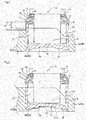
- FIG. 1 illustrates a first example of a first embodiment of the present invention.
- a feature of the first embodiment of the present invention, including this first example, is that in order to achieve construction of a shell-type needle bearing and cross-type universal joint that are capable of both lowering cost and maintaining durability, a film that is formed on the surface of the shell-type outer ring for protecting against corrosion is devised.
- the construction and function of the other parts are the same as in the conventional construction, so drawings and explanations of identical parts will be omitted or simplified, such that the explanation below centers on the features of the present invention,
- the shell-type outer ring 9a of the shell-type needle bearing 4a of this example is formed by bending a metal plate and comprises: a cylindrical section 11; a bottom plate section 12 that covers the entire one end side in the axial direction of the cylindrical section 11; and an inward facing collar section 13 that bends inward in the radial direction for the other end side in the axial direction of the cylindrical section 11.
- the outer surface of the shell-type outer ring 9a of this example in other words, the outside surface of the bottom plate section 12, the outside surface of the inward facing collar section 13 and the entire outer circumferential surface of the cylindrical section 11 is covered by a iron phosphate film, which is a chemically treated film having anti-corrosion properties.
- the method for forming this iron phosphate file is not particularly limited. It is possible to use a typical processing method such as spraying commercially sold iron phosphate first surface treatment agent, or immersing the surfaces in this first surface treatment agent. By simply performing this kind of first surface treatment on the outer surfaces of the shell-type outer ring 9a, it is possible to degrease the outer surface of the shell-type outer ring 9a, while at the same time form a chemically treated film (iron phosphate film) on the outer surfaces. It is also possible to use other well-known rust-prevention agents or base coating agents (for example, agents for forming a zinc phosphate film) as the surface treatment agent for forming a chemically treated film.
- this kind of chemically treated film will be formed at least on the outer surfaces of the shell-type outer ring 9a, and more preferably, a chemically treated film will exist on all surfaces as in this example.
- a corrosion-resistant coating 21 is formed on the end section near the opening (end section on the opposite side from the bottom plate section 12) of the outer peripheral surface of the cylindrical section 11 of the shell-type outer ring 9a, and on the outside surface of the inward-facing collar section 13 that is formed on the perimeter edge of the opening of the shell-type outer ring 9a.
- the type of material used for forming this corrosion-resistant coating 21 is not particularly limited as long as it has good adherence to the steel plate of the shell-type outer ring 9a, can be easily formed into a coating, has sufficient anti-corrosion properties, and can make the surface a flat and smooth surface.
- an epoxy resin type coating material can be used.
- the range where the coating 21 is formed is a portion that is a little larger than a portion that completely includes the portion where there is a possibility that the tip end edges of the radial lip 17 and thrust lip 18 of the seal ring 14 that are assembled at the same time in the cross-type universal joint 1a will come in sliding contact.
- the amount of elastic displacement of the yokes 2a (2b) or joint cross 3 becomes large, and the tip end edges of the seal lips 17, 18 shift from the position indicated in FIG.
- the width of the coating 21 is large enough so that these tip end edges do not separate from the coating 21. More specifically, the coating 21 exists continually from a position that reaches the inner circumferential edge of the outside surface of the inward-facing collar section 13 to a position on the outer circumferential surface of the cylindrical section 11 that enters just a little (for example, 0.5 mm to 1 mm) inside the circular holes 6a (6b).
- the coating 21 is formed in only a specified range, so in a state wherein in addition to performing masking using a cover or tape from the bottom plate section 12 to the middle section in the axial direction of the cylindrical section 11, the opening on the inner diameter side of the inward-facing collar section is covered with a cap, spray work is performed for forming the coating 21.
- Part of the coating 21 fits inside the circular holes 6a (6b), however, that portion is kept very small. Moreover, in the final stage of the work of fitting the cylindrical section 11 inside the circular holes 6a (6b) with an interference fit, this portion as well is pushed inside the circular holes 6a (6b).
- the thickness of the coating 21 is greater than the thickness of the chemically treated film, but is kept to about 0.005 mm to 0.015 mm. Therefore, the existence of the coating 21 hardly interferes with the work of fitting the shell-type needle bearing 4a inside the circular holes 6a (6b), and this coating 21 is hardly scraped off at all during the fitting work.
- Seal rings 14 are fitted onto the portion of the outer circumferential surface of the shaft sections 8 (base end sections of the shaft sections 8) that are inserted on the inner-diameter side of the needles of the shell-type needle bearing 4a that protrudes toward the other end side in the axial direction from the cylindrical section 11 (inner end side when assembled in the yokes).
- Each of the seal rings 14 comprises a base section that is fitted around and supported by the base end section of the shaft sections 8, a radial seal lip 17 that comes in sliding contact with all around the outer circumferential surface of the other end section in the axial direction of the outer surface of the shell-type outer ring 9a that protrudes from the circular hole 6a (6b), and a thrust seal lip 18 that comes in sliding contact with all around the outside surface of the inward-facing collar section 13 of the shell-type outer ring 9a of the outer surface of the shell-type outer ring 9a.
- the base end section of each of the seal lips 14 is reinforced by a ring shaped metal core 15.
- the tip end edges of the radial seal lip 17 and the thrust seal lip 18 come in sliding contact with the portion on the surface of the corrosion-resistant coating 21 that is near the center side which is sufficiently separated from the both end edges in the width direction of the coating 21.
- the surface of the coating 21 is flat and smooth, and has sufficient and excellent resistance to corrosion. Therefore, even when using for long periods of time in severe corrosive environments, the surface of the portion that comes in sliding contact with the tip end edges of the radial seal lip 17 and thrust seal lip 18 does not become rough. In other words, wear of the tip end edges of these seal lips does not advance due to rubbing against the surface of the shell-type outer ring that has become rough due to rust as occurred in the case of the conventional construction.
- FIG. 2 illustrates a second example of the first embodiment of the present invention.
- a corrosion-resistant coating 21a is formed on the outside surface of the bottom plate section 12 of the outer surface of the shell-type outer ring 9b as indicated by the dashed line ⁇ in FIG. 2 .
- This bottom plate section 12 exits in a portion that is recessed a little more than the outside surface of the yoke 2a (2b), so it becomes easy for corrosive matter such as muddy water that contains snow-melting salt to build up in the portion surrounded by the inner circumferential surface of the circular hole 6a (6b) and the bottom plate section 12, and thus the condition becomes very severe as a corrosive environment.
- FIG. 3 illustrates a third example of the first embodiment of the present invention.
- a coating 21 is formed on the outer circumferential surface of the cylindrical section 11 of the shell-type outer ring 9c on the end section near the opening, and on the outside surface of the inward-facing collar section 13, and a coating 21a is formed on the outside surface of the bottom plate section 12. Therefore, the same function and effect of the first and second examples of the first embodiment can be obtained.
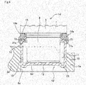
- FIG. 4 and FIG. 5 illustrate a first example of a second embodiment of the present invention.
- a feature of this second embodiment of the present invention is the construction of a seal ring 14 is devised in order to seal the space between the shaft section 8 of the joint cross 3 of a cross-type universal joint and the opening section of a shell-type outer ring 9d, and to cover necessary locations on the outer surface of the shell-type outer ring 9d with a corrosion-resistant film 21b for preventing rust.
- the seal ring 14a of the cross-type universal joint of this example comprises in order from the internal space 23 side where the needles 10 are arranged, a thrust seal lip 18, which is an inside seal lip, an intermediate seal lip 22, and a radial seal lip 17a, which is an outside seal lip, such that there are three seal lips 18, 22 and 17a.
- the base section of the seal ring 14a is also reinforced by a ring shaped metal core 15. In this example, the tip end edges of these seal lips 18, 22, 17a come in sliding contact with all around the outer surface of the shell-type outer ring 9d.
- the tip end edge of the thrust seal lip 18 comes in elastic sliding contact with all around the outside surface of the inward-facing collar section 13
- the tip end edge of the intermediate seal lip 22 comes in elastic sliding contact wit all around the continuous section between the inward-facing collar section 13 and the cylindrical section 11
- the tip end edge of the radial seal lip 17a comes in elastic sliding contact with all around the outer circumferential surface of the cylindrical section 11.
- the number of seal lips is increased from two to three, and the tip end edge of the radial seal lip 17a, which is an outside seal lip, comes in sliding contact with the straight part of the outer circumferential surface of the cylindrical section 11 that extends straight in the axial direction where the outer circumferential surface of the shell-type outer ring 9d does not change, instead of coming in sliding contact with the continuous section between the inward-facing collar section 13 and cylindrical section 11 where the outer diameter of the outer circumferential surface of the shell-type outer ring 9d changes.
- a corrosion-resistant coating 21b covers the outside surface of the in inward-facing collar section 13 and the outer surface of the continuous section between the inward-facing collar section 13 and the cylindrical section 11.
- the coating 21b does not cover the portion of the outer circumferential surface of the cylindrical section 11 that is separated from this continuous section that comes in sliding contact with the tip end edge of the radial seal lip 17a.
- the outer surface of the shell-type outer ring 9d does not absolutely need to be covered by a chemically treated film having anti-corrosive properties, however, when applied to uses in severe operating conditions, it is preferred that part or all of the shell-type outer ring 9d be covered with a chemically treated film. Particularly, when there is chemically treated film in the portion where the tip end edge of the radial seal lip 17a comes in sliding contact, wear of that portion is prevented to a certain extent.
- the thrust seal lip 18 and the intermediate seal lip 22 have the same function as the two seal lips 17, 18 in the construction of the first embodiment (see FIG. 1 ). The advancement of the wear of the tip end edges of these two seal lips 18, 22 due to rubbing against the surface of the shell-type outer ring 9 that is rough due to rust is prevented.
- this radial seal lip 17a comes in sliding contact with a portion where a corrosion-resistant coating is not formed, and that sliding contact is maintained, so there is a possibility that the tip end edge will wear due to changes in the characteristics of the outer surface of the cylindrical section 11.
- this tip end edge section may wear out, a labyrinth seal is formed between the tip end edge of this radial seal lip 17a and the outer circumferential surface of the shell-type outer ring 9d. Therefore, even when the tip end edge of the radial seal lip 17a is worn, it is possible to suppress the amount of foreign matter that enters toward the side of the two seal lips 18, 22.
- FIG. 6 illustrates a second example of the second embodiment of the present invention.
- two protruding ridges 24a, 24b are formed around the entire circumference on the tip end edge of the radial seal lip 17b that is provided on an elastic member 16b in a portion that faces the outer circumferential surface of the cylindrical section 11 of the shell-type outer ring 9d, and are such that they are separated from each other in the axial direction.
- FIG. 7 illustrates a third example of the second embodiment of the present invention.
- a protruding ridge 25 is formed on the tip end edge of the intermediate seal lip 22a that is provided on the elastic member 16c of the seal ring 14c in the portion that faces the outer surface of the shell-type outer ring 9d, and comes in sliding contact with all around this outer surface.
- the state of sliding contact between the tip end edge of the intermediate seal lip 22a and the outer surface of the shell-type outer ring 9d is stabilized, and by suitably maintaining surface pressure at these areas of contact, it is possible to improve the seal performance.
- the construction and function of the other parts are the same as in the first example of this second embodiment.
- FIG. 8 illustrates a fourth example of the second embodiment of the present invention.
- the shapes of the thrust seal lip 18a and the intermediate seal lip 22b are different than in examples 1 to 3 of this second embodiment. More specifically, these seal lips 18a, 22b are separated into two forks having the same base end in common with each other. The construction and function of the other parts are the same as in the first example of this second embodiment.
- FIG. 9 illustrates a fifth example of the second embodiment of the present invention.
- a corrosion resistant coating 21b cover the portion of the outer surface of the opening end section side of the shell-type outer ring 9e where the inward-facing collar section 13 is formed that protrudes from the inside surface of the arm section 5a of the yoke 2a that comes in sliding contact with the tip end edges of the thrust lip 18 and intermediate seal lip 22, but also covers the portion that comes in sliding contact with the radial seal lip 17a.
- a coating 21b covers the outside surface of the inward-facing collar section 13, the outer surface of the continuous section between the inward-facing collar section 13 and the cylindrical section 11, and the portion near the other end in the axial direction of the outer peripheral surface of the cylindrical section 11.
- wear of the tip end edge of the radial seal lip 17a is effectively prevented.
- the outer end section in the axial direction of the coating 21b extend up to a position that enters inside the circular hole 6a (6b) just a little (for example, 0.5 mm to 1 mm).
- the construction and function of the other parts are the same as in the first example of this second embodiment.
- the present invention can obtain a large effect when applied to a cross-type universal joint for a propeller shaft that undergoes extremely severe operating conditions from the aspect of maintaining resistance to wear, because foreign matter such as muddy water adheres easily, the operation speed is fast, and the rubbing speed between the tip end edges of the seal lips and the outer surface of the shell-type outer ring is fast.
- the present invention is not limited to a propeller shaft and could be applied for use in cross-type universal joints that are used in steering apparatuses, uses other than automobiles, or shell-type needle bearings that are used in these kinds of cross-type universal joints.
Landscapes
- Engineering & Computer Science (AREA)
- General Engineering & Computer Science (AREA)
- Mechanical Engineering (AREA)
- Manufacturing & Machinery (AREA)
- Rolling Contact Bearings (AREA)
Abstract
Description
- The present invention relates to a shell-type needle bearing that has a shell-type outer ring that is formed by bending a metal plate into a cylindrical shape with a bottom, and that is used in a state wherein the space between the opening end section of the outer ring and the outer circumferential surface of a shaft that is inserted into the inner diameter side of the outer ring is covered by a seal ring, and a cross-type universal joint in which this shell-type needle bearing is assembled.
- A cross-type universal joint can be assembled in the connecting section between the end section of a drive shaft of the drive system of an automobile and a different rotating shaft, and is capable of transmitting torque between the drive shaft and rotating shaft that are non-linearly arranged. A cross-type universal joint can be assembled between the steering shaft and intermediate shaft, or between the intermediate shaft and pinion shaft of the steering gear unit of a steering apparatus for an automobile, and can transmit torque between these shafts that are non-linearly arranged. Construction of a cross-type universal joint such as disclosed in
JP 8-135674 (A JP 9-60650 (A JP 2005-48809 (A JP 2006-29551 (A JP 2010-181015 (A JP 2010-181016 (A -
FIG. 10 illustrates an example of a conventional cross-type universal joint. This universal joint 1 joins a pair ofyokes joint cross 3 by way of four shell-type needle bearings 4 so that relative displacement is possible. Theyokes arm sections circular holes arm sections circular holes 6a (6b) that are formed on the tip end sections of thesame yoke 2a (2b) are concentric with each other. Moreover, thejoint cross 3 is formed by uniformly arranging fourshaft sections 8 in a radial manner around the outer circumferential direction of aconnection base section 7. By supporting theshaft sections 8 inside thecircular holes type needle bearings 4 so that pivotal displacement is possible, theyokes joint cross 3 such that pivotal displacement is possible and so that torque can be freely transmitted. - The shell-
type needle bearings 4 comprise one shell-typeouter ring 9 and a plurality ofneedles 10. The shell-typeouter ring 9 is formed by plastic working such as deep drawing to bend a hard metal plate, such as a carbon steel plate, and comprises acylindrical section 11, abottom plate section 12 and an inward-facingcollar section 13. Thebottom plate section 12 entirely covers one end in the axial direction of the cylindrical section 11 (outside surface side of thearm sections circular holes collar section 13 is bent inward in the radial direction from the other end in the axial direction of the cylindrical section 11 (inside surface side of thearm sections circular holes needles 10 is a concave surface. - The shell-
type needle bearings 4 are assembled with the respective shell-typeouter rings 9 fitted into the respectivecircular holes shaft sections 8 of thejoint cross 3 inserted on the inside of theneedles 10. This assembly work is performed with theshaft sections 8 inserted in thecircular holes type needle bearings 4 into thecircular holes arm sections seal ring 14 is fitted and supported beforehand around the base end section of theshaft sections 8 with an interference fit. In the assembled state, the inner circumferential surface of thecylindrical section 11 of the shell-typeouter ring 9 functions as an outer ring raceway, and the outer circumferential surface of theshaft section 8 functions as an inner ring raceway. - The
seal ring 14 is formed such that anelastic member 16 is reinforced by ametal core 15. Theelastic member 16 comprises aradial seal lip 17 and athrust seal lip 18. When thejoint cross 3 and shell-typeouter ring 9 are combined and to form the universal joint 1, the edge on the tip end of theradial seal lip 17 comes in elastic contact around the entire circumference of the portion of the outer circumferential surface of the shell-typeouter ring 9 near the opening end. In this state, theseal ring 14 seals the inner space of the shell-typeouter ring 9 from the external space, and together with preventing lubricant such as grease and the like that is on the inside of the shell-typeouter ring 9 from leaking to the outside, prevents foreign matter from getting inside the shell-typeouter ring 9 from the outside. The shape of the seal lip, as disclosed inJP 2010-181015 (A JP 2010-181016 (A - When using a universal joint 1 that is constructed in this way and assembled in the connecting section between the end section of a drive shaft and another rotating shaft, from the aspect of both making the universal less expensive and maintaining durability, there is room for improvement as will be described below. First, in order to reduce costs, carbon steel plate such as case hardening steel or bearing steel having a low procurement cost is preferably used as the metal plate for the shell-type
outer ring 9 that is assembled in the shell-type needle bearing 4. However, in the case of carbon steel plate, when used in severe operating conditions, corrosion of the surface cannot be avoided. For example, in the case of assembling a universal joint 1 in the drive system of an automobile, such as in the propeller shaft, corrosive material such as muddy water that is splashed up as the vehicle travels, or water that is mixed with a snow melting agent adheres to the surface of the shell-typeouter ring 9, and rusting occurs on this surface. - The portion of the surface of the shell-type
outer ring 9 where rusting occurs becomes rough, or in other words, becomes a rough surface having a large friction coefficient, so there is strong friction against the tip end edges of theseal lips seal ring 14, and thus wear of theseseal lips FIG. 11A , in the initial stage, even when the tip end edges of theseal lips outer ring 9 such that there are no spaces, whenrust 19 occurs on part of the surface of the shell-typeouter ring 9 as illustrated inFIG. 11B , first, the edge of the tip end of theradial seal lip 17 wears due to rubbing against thisrust 19. As a result, aspace 20 occurs between the tip end edge of thisradial seal lip 17 and the surface of the shell-typeouter ring 9. Consequently, corrosive material enters through thisspace 20 beyond theradial seal lip 17, and as illustrated inFIG. 11C ,rust 19a occurs on the surface of the shell-typeouter ring 9 that reaches the deep section. Due to rubbing against thisrust 19a, the tip end edge of thethrust seal lip 18 also wears, and aspace 20a also occurs between the tip end edge of thisthrust seal lip 18 and the surface of the shell-typeouter ring 9. As a result, the seal by theseal lips - As disclosed in
JP 2010-181015 (A - By constructing the shell-type
outer ring 9 using stainless steel plate, it is possible to suppress the occurrence ofrust -
JP 2002-146837 (A JP 2002-294465 (A -
- [Patent Literature 1]
JP 8-136674 (A - [Patent Literature 2]
JP 9-60650 (A - [Patent Literature 3]
JP 2005-48809 (A - [Patent Literature 4]
JP 2006-29551 (A - [Patent Literature 5]
JP 2010-181015 (A - [Patent Literature 6]
JP 2010-181016 (A - [Patent Literature 7]
JP 2002-146837 (A - [Patent Literature 8]
JP 2002-294465 (A - In consideration of the situation above, the object of the present invention is to achieve construction of a shell-type needle bearing and cross-type universal joint that are capable of both lowering cost and maintaining durability.
- Particularly, the object of the present invention is to achieve construction of a cross-type universal joint that, even when used under severe operating conditions, is capable of suppressing wear of the tip end edges of the seal lips of a seal ring that is provided between the base end section of the shaft section of the joint cross and the opening section of a shell-type outer ring of a shell-type needle bearing, and is capable of preventing foreign matter from getting inside the shell-type outer ring.
- The shell-type needle bearing of the present invention, comprises:
- a shell-type outer ring that is formed by bending a metal plate and comprises a cylindrical section, a bottom plate section that covers the entire one end side in the axial direction of the cylindrical section, and an inward-facing collar section that is bent inward in the radial direction from the other end side in the axial direction of the cylindrical section, this shell-type outer ring during use being fastened inside a circular hole that is formed in an outside member; and
- a plurality of needles that are provided on the inner-diameter side of the shell-type outer ring so as to be able to roll freely; and
- at least part of a portion of the outer surface of the shell-type outer ring that is separated from the circular hole is covered by a corrosion resistant coating.
- Preferably, as at least the part of a portion that is separated from the circular hole, a portion near the other end in the axial direction of the outer surface of the shell-type outer ring, where there is a possibility that a tip end edge of a seal lip of a seal ring that is fitted around and fastened to the outer circumferential surface of a shaft section that is inserted into the inner-diameter side of the needles will come in sliding contact, is covered by the corrosion resistant coating.
- Of the portion where the there is a possibility that the tip end edge of the seal lip will come in sliding contact, the outside surface of the inward-facing collar section and the outer surface of the continuous section between this inward-facing collar section and the cylindrical section may be selectively covered by the corrosion resistant coating.
- Alternatively or additionally, it is preferred that the bottom plate section be located on the inside of the circular hole, and the outside surface of this bottom plate section be covered by the corrosion resistant coating.
- Particularly, it is preferred that when used in a cross-type universal joint that is applied to uses subjected to severe operating conditions, the entire outer surface of the shell-type outer ring be covered by a chemically treated film having anti-corrosion properties.
- The cross-type universal joint of the present invention comprises:
- a pair of yokes that are formed in a forked shape and comprises a pair of arm sections, and circular holes that are formed in the tip end sections of the arm sections so as to be concentric with each other;
- a joint cross that comprises a connection base section, and four shaft sections that are fastened to the outer circumferential surface of the connection base section in a radial manner, and that is combined with the pair of yokes with the shaft sections inserted inside the circular holes respectively; and
- four shell-type needle bearings that are provided between the outer circumferential surfaces of the shaft sections and the inner circumferential surfaces of the circular holes; and
- each of the shell-type needle bearings is any one of the shell-type needle bearings of the present of the present invention described above.
- The cross-type universal joint of the present invention further comprises four seal rings, each of the four seal rings having:
- a base section that is fastened around and supported by the base end section of each of the shaft sections; and
- a radial seal lip and a thrust seal lip that are provided between the base end section of each of the shaft sections and the opening section of each of the shell-type outer rings, the radial seal lip coming in sliding contact with all around the circumferential surface of the other end section in the axial direction that protrudes from the circular hole of the outer surface of the shell-type outer ring, and the thrust seal lip coming in sliding contact with all around the outside surface of the inward-facing collar section of the shell-type outer ring; and
- the other end sections in the axial direction of the outer circumferential surface of the cylindrical section and the outside surface of the inward-facing collar section of each of the shell-type outer rings are continuously covered with the corrosion resistant coating.
- Alternatively, the cross-type universal joint of the present invention further comprises four seal rings, each of the four seal rings having:
- a base section that is fastened around and supported by the base end section of each of the shaft sections; and
- seal lips that are provided between the base end section of each of the shaft sections and the opening section of each of the shell-type outer rings, each of the seal lips comprising a tip end edge that comes in sliding contact with all around the outer surface of a portion on the other end side in the axial direction of each of the shell-type outer ring that protrudes from the inside surface of the arm section; and
- a portion of the outer surface of the portion on the other end side in the axial direction of each of the shell-type outer ring that protrudes from the inside surface of the arm section that comes in sliding contact with the tip end edges of at least two of the seal lips other than the outermost seal lip, is covered with the corrosion resistant coating.
- Technology of forming a chemically treated film over the entire surface of the shell-type needle bearing of the present invention in order to provide the entire surface with a certain amount of resistance to corrosion, with forming a coating for improving corrosion resistance on only the necessary portions that particularly require a high degree of resistance to corrosion can also be applied to rolling bearings other than a shell-type needle bearing. In other words, in a radial rolling bearing that comprises an outer ring having an outer ring raceway formed around the inner circumferential surface, an inner ring having an inner ring raceway formed around the outer circumferential surface, and a plurality of rolling elements that are located between the outer ring raceway and inner ring raceway so as to be able to roll freely, it is possible to obtain the same function and effect by covering the entire outer surface of at least one of the rings, in other words the outer ring and inner ring, that are formed using bearing steel by performing forging, machining, and grinding with a chemically treated film having anti-corrosion properties, and covering only a portion which is a part of the outer surface of this ring and where there is a possibility that the tip end edges of seal lips will come in sliding contact with a coating for improving corrosion resistance.
- In the case of the shell-type needle bearing and cross-type universal joint of the present invention, basically a corrosion resistant coating is not formed on the portion of the outer circumferential surface of the shell-type outer ring that fits inside a circular hole in an outside member (tip end section of the arm section of the yoke) with an interference fit, and in the case that a corrosion resistant coating is used, the thickness is extremely small. On the other hand, in the case of uses in particularly severe operating conditions, only a chemically treated film is used. The film thickness of this chemically treated film is very thin, so hardly increases the dimension of the outer diameter of the shell-type outer ring. Therefore, fitting and fastening the shell-type outer ring inside the circular hole of the outside member with an interference fit can be performed with no problem, and hardly any shavings occur due to part of the film scraping off during the fitting work.
- On the other hand, portions that require a particularly high degree of resistance to corrosion such as the portions that come in sliding contact with the seal lips are selectively covered with corrosion resistant film, so rusting of these portions is completely prevented. Therefore, the advancement of wear of the tip end edges of the seal lips due to rubbing against the surface of the shell-type outer ring that is rough due to rusting (corrosion products) is effectively prevented. With the construction of the present invention, a shell-type needle bearing and cross-type universal joint is achieved for which cost can be lowered and durability can be maintained.
- Moreover, in the cross-type universal joint of the present invention, in the case of a seal ring having three seal lips, there is a low possibility of foreign matter passing through all of the areas of sliding contact between the tip end edges of these three seal lips and the outer surface of the shell-type outer rings and getting inside the shell-type outer rings. Moreover, portions on the outer surface of the shell-type outer rings that come in sliding contact with the tip end edges of at least two seal lips, except for the seal lip that is the furthest on the outside, are covered with a corrosion resistant coating, so that advancement of wear of the tip end edges of at least these two seal lips due to rust occurring on the outer surface of the shell-type outer ring is suppressed. Even in the case where wear of the tip end edge of the outermost seal lip occurs, a labyrinth seal is formed with the outer circumferential surface of the shell-type outer ring, so the function of suppress the amount of foreign matter that gets inside at least the two seal lips is maintained. As a result, due to these three seal lips, it is possible to maintain well the effect of preventing foreign matter from getting inside the shell-type outer rings over a long period of time, and it is possible to adequately maintain the durability of the cross-type universal joint.
-
-
FIG. 1 is a cross-sectional view illustrating the main parts of a first example of a first embodiment of the present invention. -
FIG. 2 is a cross-sectional view illustrating the main parts of a second example of a first embodiment of the present invention. -
FIG. 3 is a cross-sectional view illustrating the main parts of a third example of a first embodiment of the present invention. -
FIG. 4 is a cross-sectional view illustrating the main parts of a first example of a second embodiment of the present invention. -
FIG. 5 is an enlarged view of the upper left portion ofFIG. 4 . -
FIG. 6 illustrates a second example of a second embodiment of the present invention, and is similar toFIG. 5 . -
FIG. 7 illustrates a third example of a second embodiment of the present invention, and is similar toFIG. 5 . -
FIG. 8 illustrates a fourth example of a second embodiment of the present invention, and is similar toFIG. 5 . -
FIG. 9 illustrates a fifth example of a second embodiment of the present invention, and is similar toFIG. 5 . -
FIG. 10 is a partial cross-sectional view illustrating a universal joint in which a shell-type needle bearing of the present invention is assembled, with part of the being omitted. -
FIG. 11A to FIG. 11C are partial cross-sectional views illustrating the main parts in order of advancement of wear of the tip end section of seal lips of a seal ring due to corrosion of the outer surface of a shell-type outer ring. -
FIG. 1 illustrates a first example of a first embodiment of the present invention. A feature of the first embodiment of the present invention, including this first example, is that in order to achieve construction of a shell-type needle bearing and cross-type universal joint that are capable of both lowering cost and maintaining durability, a film that is formed on the surface of the shell-type outer ring for protecting against corrosion is devised. The construction and function of the other parts are the same as in the conventional construction, so drawings and explanations of identical parts will be omitted or simplified, such that the explanation below centers on the features of the present invention, - The shell-type
outer ring 9a of the shell-type needle bearing 4a of this example is formed by bending a metal plate and comprises: acylindrical section 11; abottom plate section 12 that covers the entire one end side in the axial direction of thecylindrical section 11; and an inwardfacing collar section 13 that bends inward in the radial direction for the other end side in the axial direction of thecylindrical section 11. The outer surface of the shell-typeouter ring 9a of this example, in other words, the outside surface of thebottom plate section 12, the outside surface of the inward facingcollar section 13 and the entire outer circumferential surface of thecylindrical section 11 is covered by a iron phosphate film, which is a chemically treated film having anti-corrosion properties. The method for forming this iron phosphate file is not particularly limited. It is possible to use a typical processing method such as spraying commercially sold iron phosphate first surface treatment agent, or immersing the surfaces in this first surface treatment agent. By simply performing this kind of first surface treatment on the outer surfaces of the shell-typeouter ring 9a, it is possible to degrease the outer surface of the shell-typeouter ring 9a, while at the same time form a chemically treated film (iron phosphate film) on the outer surfaces. It is also possible to use other well-known rust-prevention agents or base coating agents (for example, agents for forming a zinc phosphate film) as the surface treatment agent for forming a chemically treated film. Moreover, before performing the chemical treatment, it is also possible to perform separate degreasing using a well-known degreasing agent. Furthermore, depending on the conditions for use, it may also be possible to omit the formation of a chemically treated film. However, preferably, except for the areas of contact with the inner surfaces of thecircular section 11, this kind of chemically treated film will be formed at least on the outer surfaces of the shell-typeouter ring 9a, and more preferably, a chemically treated film will exist on all surfaces as in this example. - Furthermore, the portion of the outer surface of the shell-type
outer ring 9a that is indicated by the dashed line α inFIG. 1 is covered by a corrosion-resistant coating 21. In other words, a corrosion-resistant coating 21 is formed on the end section near the opening (end section on the opposite side from the bottom plate section 12) of the outer peripheral surface of thecylindrical section 11 of the shell-typeouter ring 9a, and on the outside surface of the inward-facingcollar section 13 that is formed on the perimeter edge of the opening of the shell-typeouter ring 9a. The type of material used for forming this corrosion-resistant coating 21 is not particularly limited as long as it has good adherence to the steel plate of the shell-typeouter ring 9a, can be easily formed into a coating, has sufficient anti-corrosion properties, and can make the surface a flat and smooth surface. For example, preferably an epoxy resin type coating material can be used. - In this example, based on the torque that is applied between the
yokes 2a (2b) and thejoint cross 3 when assembled in the cross-type universal joint 1a, the range where thecoating 21 is formed is a portion that is a little larger than a portion that completely includes the portion where there is a possibility that the tip end edges of theradial lip 17 and thrustlip 18 of theseal ring 14 that are assembled at the same time in the cross-type universal joint 1a will come in sliding contact. In other words, even when the torque becomes large, the amount of elastic displacement of theyokes 2a (2b) orjoint cross 3 becomes large, and the tip end edges of theseal lips FIG. 1 , the width of thecoating 21 is large enough so that these tip end edges do not separate from thecoating 21. More specifically, thecoating 21 exists continually from a position that reaches the inner circumferential edge of the outside surface of the inward-facingcollar section 13 to a position on the outer circumferential surface of thecylindrical section 11 that enters just a little (for example, 0.5 mm to 1 mm) inside thecircular holes 6a (6b). In other words, when the protruding amount of the shell-typeouter ring 9a from the inside surface of the portion except the tip end section of the inside surface ofarm sections 5a (5b) of theyokes 2a (2b) is taken to be H, and the distance from the other end surface of this shell-typeouter ring 9a (outside surface of the inward-facing collar section 13) to the end section on one end in the axial direction of thecoating 21 is taken to W, then W - H = 0.5 mm to 1 mm. Thecoating 21 is formed in only a specified range, so in a state wherein in addition to performing masking using a cover or tape from thebottom plate section 12 to the middle section in the axial direction of thecylindrical section 11, the opening on the inner diameter side of the inward-facing collar section is covered with a cap, spray work is performed for forming thecoating 21. - With the construction above, it is possible to both lower costs and maintain durability of a shell-
type needle bearing 4a and a cross-type universal joint 1a in which the shell-type needle bearing 4a is assembled. In other words, in the case of the construction of this example, only a chemically treated film exists in a large portion of the portion on the outer circumferential surface of thecylindrical section 11 of the shell-typeouter ring 9a that fits inside thecircular holes 6a (6b) of theyokes 2a (2b) with an interference fit. The film thickness of this chemically treated film is very thin, so it hardly increases the dimension of the outer diameter of the shell-typeouter ring 9a. Part of the coating 21 (part in the circumferential direction of the portion having a 0.5 mm to 1 mm width) fits inside thecircular holes 6a (6b), however, that portion is kept very small. Moreover, in the final stage of the work of fitting thecylindrical section 11 inside thecircular holes 6a (6b) with an interference fit, this portion as well is pushed inside thecircular holes 6a (6b). In this example, the thickness of thecoating 21 is greater than the thickness of the chemically treated film, but is kept to about 0.005 mm to 0.015 mm. Therefore, the existence of thecoating 21 hardly interferes with the work of fitting the shell-type needle bearing 4a inside thecircular holes 6a (6b), and thiscoating 21 is hardly scraped off at all during the fitting work. - In the completed assembled state of the cross-type universal joint 1a, as illustrated in
FIG. 1 , fourshaft sections 8 that are fastened around the outer circumferential surface of theconnection base section 7 of thejoint cross 3 are respectively inserted inside thecircular holes 6a (6b) that are formed in the tip end sections of thearm sections 5a (5b) of theyokes 2a (2b) by way of the shell-type needle bearing 4a of this example. Seal rings 14 are fitted onto the portion of the outer circumferential surface of the shaft sections 8 (base end sections of the shaft sections 8) that are inserted on the inner-diameter side of the needles of the shell-type needle bearing 4a that protrudes toward the other end side in the axial direction from the cylindrical section 11 (inner end side when assembled in the yokes). Each of the seal rings 14 comprises a base section that is fitted around and supported by the base end section of theshaft sections 8, aradial seal lip 17 that comes in sliding contact with all around the outer circumferential surface of the other end section in the axial direction of the outer surface of the shell-typeouter ring 9a that protrudes from thecircular hole 6a (6b), and athrust seal lip 18 that comes in sliding contact with all around the outside surface of the inward-facingcollar section 13 of the shell-typeouter ring 9a of the outer surface of the shell-typeouter ring 9a. The base end section of each of theseal lips 14 is reinforced by a ring shapedmetal core 15. - In this example, the tip end edges of the
radial seal lip 17 and thethrust seal lip 18 come in sliding contact with the portion on the surface of the corrosion-resistant coating 21 that is near the center side which is sufficiently separated from the both end edges in the width direction of thecoating 21. The surface of thecoating 21 is flat and smooth, and has sufficient and excellent resistance to corrosion. Therefore, even when using for long periods of time in severe corrosive environments, the surface of the portion that comes in sliding contact with the tip end edges of theradial seal lip 17 and thrustseal lip 18 does not become rough. In other words, wear of the tip end edges of these seal lips does not advance due to rubbing against the surface of the shell-type outer ring that has become rough due to rust as occurred in the case of the conventional construction. -
FIG. 2 illustrates a second example of the first embodiment of the present invention. In this example, a corrosion-resistant coating 21a is formed on the outside surface of thebottom plate section 12 of the outer surface of the shell-typeouter ring 9b as indicated by the dashed line β inFIG. 2 . Thisbottom plate section 12 exits in a portion that is recessed a little more than the outside surface of theyoke 2a (2b), so it becomes easy for corrosive matter such as muddy water that contains snow-melting salt to build up in the portion surrounded by the inner circumferential surface of thecircular hole 6a (6b) and thebottom plate section 12, and thus the condition becomes very severe as a corrosive environment. Typically, by forming a chemically treated film having corrosion resistant properties on the outer surface of the shell-typeouter ring 9b, corrosion that will bring about an occurrence of through holes and a decrease in strength in the bottom plate section does not occur. However, by forming a corrosion-resistant film 21a on thebottom plate section 12 as in the construction of this example, it is possible to further improve the durability of thisbottom plate section 12. The characteristics of the coating material of thiscoating 21a are the same as those of the coating material of thecoating 21 of the first example. -
FIG. 3 illustrates a third example of the first embodiment of the present invention. In this example, acoating 21 is formed on the outer circumferential surface of thecylindrical section 11 of the shell-typeouter ring 9c on the end section near the opening, and on the outside surface of the inward-facingcollar section 13, and acoating 21a is formed on the outside surface of thebottom plate section 12. Therefore, the same function and effect of the first and second examples of the first embodiment can be obtained. -
FIG. 4 andFIG. 5 illustrate a first example of a second embodiment of the present invention. A feature of this second embodiment of the present invention is the construction of aseal ring 14 is devised in order to seal the space between theshaft section 8 of thejoint cross 3 of a cross-type universal joint and the opening section of a shell-typeouter ring 9d, and to cover necessary locations on the outer surface of the shell-typeouter ring 9d with a corrosion-resistant film 21b for preventing rust. - The
seal ring 14a of the cross-type universal joint of this example comprises in order from the internal space 23 side where theneedles 10 are arranged, athrust seal lip 18, which is an inside seal lip, anintermediate seal lip 22, and aradial seal lip 17a, which is an outside seal lip, such that there are threeseal lips seal ring 14a is also reinforced by a ring shapedmetal core 15. In this example, the tip end edges of theseseal lips outer ring 9d. In other words, the tip end edge of thethrust seal lip 18 comes in elastic sliding contact with all around the outside surface of the inward-facingcollar section 13, the tip end edge of theintermediate seal lip 22 comes in elastic sliding contact wit all around the continuous section between the inward-facingcollar section 13 and thecylindrical section 11, and the tip end edge of theradial seal lip 17a comes in elastic sliding contact with all around the outer circumferential surface of thecylindrical section 11. - In this second embodiment of the present invention, differing from the first embodiment of the invention, the number of seal lips is increased from two to three, and the tip end edge of the
radial seal lip 17a, which is an outside seal lip, comes in sliding contact with the straight part of the outer circumferential surface of thecylindrical section 11 that extends straight in the axial direction where the outer circumferential surface of the shell-typeouter ring 9d does not change, instead of coming in sliding contact with the continuous section between the inward-facingcollar section 13 andcylindrical section 11 where the outer diameter of the outer circumferential surface of the shell-typeouter ring 9d changes. By causing the tip end edge of theradial seal lip 17a to come in sliding contact with the straight part of the outer circumferential surface of the shell-typeouter ring 9d in this way, even when theradial seal lip 17a displaces in the axial direction due to torque that is applied between theyoke 1a (2b) and thejoint cross 3, the contact pressure (surface pressure) between theradial seal lip 17a and the outer circumferential surface of the shell-typeouter ring 9d does not change, and it is possible to avoid the effect caused of space occurring in the axial direction. - Furthermore, on the opening end section side of the shell-type
outer ring 9d where the inward-facingcollar section 13 is formed, the portion of the outer surface of the portion that protrudes from the inside surface of thearm section 5a of theyoke 2a where the tip end edges of thethrust lip 18 andintermediate lip 22 coming in sliding contact is covered by a corrosion-resistant coating 21b. In other words, acoating 21b covers the outside surface of the in inward-facingcollar section 13 and the outer surface of the continuous section between the inward-facingcollar section 13 and thecylindrical section 11. Thecoating 21b does not cover the portion of the outer circumferential surface of thecylindrical section 11 that is separated from this continuous section that comes in sliding contact with the tip end edge of theradial seal lip 17a. The outer surface of the shell-typeouter ring 9d does not absolutely need to be covered by a chemically treated film having anti-corrosive properties, however, when applied to uses in severe operating conditions, it is preferred that part or all of the shell-typeouter ring 9d be covered with a chemically treated film. Particularly, when there is chemically treated film in the portion where the tip end edge of theradial seal lip 17a comes in sliding contact, wear of that portion is prevented to a certain extent. - With the cross-type universal joint of this example, even under severe operating conditions, it is difficult for foreign matter to get inside the shell-type
outer ring 9d, and it is possible to achieve a cross-type universal joint for which is easier to maintain sufficient durability. In other words, with the construction of this example, thethrust seal lip 18 and theintermediate seal lip 22 have the same function as the twoseal lips FIG. 1 ). The advancement of the wear of the tip end edges of these twoseal lips outer ring 9 that is rough due to rust is prevented. - Furthermore, in the case of the construction of this example, due to the existence of a
radial seal lip 17a that is located the furthest on the outside, it is possible to lower the possibility of foreign matter on the outside from getting inside the internal space 23. Particularly, in this example, the tip end edge of theradial seal lip 17a comes in sliding contact with the straight portion of the outer circumferential surface of the shell-typeouter ring 9d where there is no change in the outer diameter, so effects that are received due to the occurrence of spaces in the axial direction are prevented, and the seal performance is maintained. The tip end edge of thisradial seal lip 17a comes in sliding contact with a portion where a corrosion-resistant coating is not formed, and that sliding contact is maintained, so there is a possibility that the tip end edge will wear due to changes in the characteristics of the outer surface of thecylindrical section 11. However, even though this tip end edge section may wear out, a labyrinth seal is formed between the tip end edge of thisradial seal lip 17a and the outer circumferential surface of the shell-typeouter ring 9d. Therefore, even when the tip end edge of theradial seal lip 17a is worn, it is possible to suppress the amount of foreign matter that enters toward the side of the twoseal lips intermediate seal lip 22 and thethrust seal lip 18 and the outer surface of the shell-typeouter ring 9d to a small amount, and the effect of preventing foreign matter from getting into the internal space 23 can be maintained well over a long period of time, so it is possible to adequately maintain the durability of the cross-type universal joint 1d. The construction and function of the other parts are the same as in the first embodiment. -
FIG. 6 illustrates a second example of the second embodiment of the present invention. In the case of this example, two protrudingridges elastic member 16b in a portion that faces the outer circumferential surface of thecylindrical section 11 of the shell-typeouter ring 9d, and are such that they are separated from each other in the axial direction. When theseal ring 14b is assembled in the universal joint, of these protrudingridges ridge 24a that is on the tip end side comes in sliding contact with the outer circumferential surface of thecylindrical section 11, and the tip end edge of the protrudingridge 24b on the base end side is separated a little from this outer circumferential surface. - In the case of the construction of this example, as the protruding
ridge 24a of the tip end side wears over a long period of use, the protrudingridge 24b on the base end side that up to that point was separated from the outer circumferential surface of thecylindrical section 11 comes into sliding contact with this outer circumferential surface. After that, even when the protrudingridge 24b becomes worn, a labyrinth seal is formed between the tip end edge of the radial seal lip 17b and the outer circumferential surface of the shell-typeouter ring 9d. As a result, the seal performance of the radial seal lip 17b can be more adequately maintained over a long period of time. The construction and function of the other parts are the same as in the first example of this second embodiment. -
FIG. 7 illustrates a third example of the second embodiment of the present invention. In the case of this example, a protrudingridge 25 is formed on the tip end edge of theintermediate seal lip 22a that is provided on theelastic member 16c of theseal ring 14c in the portion that faces the outer surface of the shell-typeouter ring 9d, and comes in sliding contact with all around this outer surface. In the case of the construction of this example, the state of sliding contact between the tip end edge of theintermediate seal lip 22a and the outer surface of the shell-typeouter ring 9d is stabilized, and by suitably maintaining surface pressure at these areas of contact, it is possible to improve the seal performance. The construction and function of the other parts are the same as in the first example of this second embodiment. -
FIG. 8 illustrates a fourth example of the second embodiment of the present invention. In the case of this example, the shapes of thethrust seal lip 18a and theintermediate seal lip 22b are different than in examples 1 to 3 of this second embodiment. More specifically, theseseal lips -
FIG. 9 illustrates a fifth example of the second embodiment of the present invention. In the case of this example, no only does a corrosionresistant coating 21b cover the portion of the outer surface of the opening end section side of the shell-typeouter ring 9e where the inward-facingcollar section 13 is formed that protrudes from the inside surface of thearm section 5a of theyoke 2a that comes in sliding contact with the tip end edges of thethrust lip 18 andintermediate seal lip 22, but also covers the portion that comes in sliding contact with theradial seal lip 17a. In other words, acoating 21b covers the outside surface of the inward-facingcollar section 13, the outer surface of the continuous section between the inward-facingcollar section 13 and thecylindrical section 11, and the portion near the other end in the axial direction of the outer peripheral surface of thecylindrical section 11. As a result, wear of the tip end edge of theradial seal lip 17a is effectively prevented. It is also possible to have the outer end section in the axial direction of thecoating 21b extend up to a position that enters inside thecircular hole 6a (6b) just a little (for example, 0.5 mm to 1 mm). The construction and function of the other parts are the same as in the first example of this second embodiment. - The present invention can obtain a large effect when applied to a cross-type universal joint for a propeller shaft that undergoes extremely severe operating conditions from the aspect of maintaining resistance to wear, because foreign matter such as muddy water adheres easily, the operation speed is fast, and the rubbing speed between the tip end edges of the seal lips and the outer surface of the shell-type outer ring is fast. However, the present invention is not limited to a propeller shaft and could be applied for use in cross-type universal joints that are used in steering apparatuses, uses other than automobiles, or shell-type needle bearings that are used in these kinds of cross-type universal joints.
-
- 1, 1a to 1d
- Universal joint
- 2 a, 2b
- Yoke
- 3
- Joint cross
- 4, 4a to 4h
- Shell-type needle bearing
- 5a, 5b
- Arm section
- 6a, 6b
- Circular hole
- 7
- Connection base section
- 8
- Shaft section
- 9, 9a to 9d
- Shell-type outer ring
- 10
- Needle
- 11
- Cylindrical section
- 12
- Bottom plate section
- 13
- Inward-facing collar section
- 14, 14a to 14c
- Seal ring
- 15
- Metal core
- 16, 16a to 16c
- Elastic member
- 17, 17a, 17b
- Radial seal lip
- 18, 18a
- Thrust seal lip
- 19, 19a
- Rust
- 20, 20a
- Space
- 21, 21a
- Coating
- 22, 22a, 22b
- Intermediate seal lip
- 23
- Internal space
- 24a, 24b
- Protruding ridge
- 25
- Protruding ridge
Claims (9)
- A shell-type needle bearing, comprising:a shell-type outer ring that is formed by bending a metal plate and comprises a cylindrical section, a bottom plate section that covers the entire one end side in the axial direction of the cylindrical section, and an inward-facing collar section that is bent inward in the radial direction from the other end side in the axial direction of the cylindrical section, this shell-type outer ring during use being fastened inside a circular hole that is formed in an outside member; anda plurality of needles that are provided on the inner-diameter side of the shell-type outer ring so as to be able to roll freely; andat least part of a portion of the outer surface of the shell-type outer ring that is separated from the circular hole is covered by a corrosion resistant coating.
- The shell-type needle bearing according to claim 1, wherein a portion near the other end in the axial direction of the outer surface of the shell-type outer ring, where there is a possibility that a tip end edge of a seal lip of a seal ring that is fitted around and fastened to the outer circumferential surface of a shaft section that is inserted into the inner-diameter side of the needles will come in sliding contact, is covered by the corrosion resistant coating.
- The shell-type needle bearing according to claim 2, wherein the outside surface of the inward-facing collar section and the outer surface of a continuous section between the inward-facing collar section and the cylindrical section are selectively covered by the corrosion resistant coating.
- The shell-type needle bearing according to claim 1, wherein the bottom plate section is located on the inside of the circular hole, and the outside surface of this bottom plate section is covered by the corrosion resistant coating.
- The shell-type needle bearing according to claim 1, wherein the entire outer surface of the shell-type outer ring is covered by a chemically treated film having anti-corrosion properties.
- A cross-type universal joint, comprising:a pair of yokes that are formed in a forked shape and comprises a pair of arm sections, and circular holes that are formed in the tip end sections of the arm sections so as to be concentric with each other;a joint cross that comprises a connection base section, and four shaft sections that are fastened to the outer circumferential surface of the connection base section in a radial manner, and that combined with the pair of yokes with the shaft sections inserted inside the circular holes respectively; andfour shell-type needle bearings that are provided between the outer circumferential surfaces of the shaft sections and the inner circumferential surfaces of the circular holes; whereinthe shell-type needle bearings are shell-type needle bearings according to any one of the claims 1 to 5.
- The cross-type universal joint according to claim 6, further comprising four seal rings, each of the seal rings having:a base section that is fastened around and supported by the base end section of each of the shaft sections; anda radial seal lip and a thrust seal lip that are provided between the base end section of each of the shaft sections and the opening section of each of the shell-type outer rings, the radial seal lip coming in sliding contact with all around the outer circumferential surface in the other end section in the axial direction of the outer surface of the shell-type outer ring that protrudes from the circular hole, and the thrust seal lip coming in sliding contact with all around the outside surface of the inward-facing collar section of the outer surface of the shell-type outer ring; whereinthe other end sections in the axial direction of the outer circumferential surface of the cylindrical section and the outside surface of the inward-facing collar section of each of the shell-type outer rings are continuously covered with a corrosion resistant coating.
- The cross-type universal joint according to claim 8, further comprising four seal rings, each of the seal rings having:a base section that is fastened around and supported by the base end section of each of the shaft sections; andseal lips that are provided between the base end section of each of the shaft sections and the opening section of each of the shell-type outer rings, each of the seal lips having a tip end edge that comes in sliding contact with all around the outer surface of a portion on the other end side in the axial direction of the shell-type outer ring that protrudes from the inside surface of the arm section; whereina portion of the outer surface of the portion on the other end side in the axial direction of each of the shell-type outer ring that protrudes from the inside surface of the arm section that comes in sliding contact with the tip end edges of at least two of the seal lips other than a seal lip that is the furthest on the outside of the seal lips, is covered with the corrosion resistant coating.
- The cross-type universal joint according to claim 8, wherein the portion of the outer surface of the portion on the other end side in the axial direction of each of the shell-type outer ring that protrudes from the inside surface of the arm section that comes in sliding contact with the tip end edges of all of the seal lips, is covered with the corrosion resistant coating.
Applications Claiming Priority (3)
| Application Number | Priority Date | Filing Date | Title |
|---|---|---|---|
| JP2011013845A JP5760452B2 (en) | 2011-01-26 | 2011-01-26 | Shell type needle bearing and cross shaft type universal joint |
| JP2011274112 | 2011-12-15 | ||
| PCT/JP2012/051555 WO2012102306A1 (en) | 2011-01-26 | 2012-01-25 | Shell type needle bearing and joint cross type universal joint |
Publications (3)
| Publication Number | Publication Date |
|---|---|
| EP2669539A1 true EP2669539A1 (en) | 2013-12-04 |
| EP2669539A4 EP2669539A4 (en) | 2014-10-15 |
| EP2669539B1 EP2669539B1 (en) | 2016-10-12 |
Family
ID=46580871
Family Applications (1)
| Application Number | Title | Priority Date | Filing Date |
|---|---|---|---|
| EP12739717.2A Not-in-force EP2669539B1 (en) | 2011-01-26 | 2012-01-25 | Shell type needle bearing and joint cross type universal joint |
Country Status (5)
| Country | Link |
|---|---|
| US (1) | US8939844B2 (en) |
| EP (1) | EP2669539B1 (en) |
| CN (1) | CN102812259B (en) |
| CA (1) | CA2795186C (en) |
| WO (1) | WO2012102306A1 (en) |
Families Citing this family (7)
| Publication number | Priority date | Publication date | Assignee | Title |
|---|---|---|---|---|
| JP6255670B2 (en) * | 2013-01-21 | 2018-01-10 | 株式会社ジェイテクト | Cross shaft joint and vehicle steering apparatus using the same |
| DE102015212829A1 (en) * | 2015-07-09 | 2017-01-12 | Schaeffler Technologies AG & Co. KG | Cylindrical roller bearing and method for manufacturing a cylindrical roller bearing |
| EP3130814B1 (en) * | 2015-08-11 | 2019-06-12 | Spicer Gelenkwellenbau GmbH | Guard ring, sealing assembly and stud cross fitting |
| DE102017205270A1 (en) | 2017-02-09 | 2018-09-20 | Aktiebolaget Skf | Universal joint bearings |
| DE102017109300B4 (en) * | 2017-05-02 | 2024-10-17 | Schaeffler Technologies AG & Co. KG | coating system for universal joint bushings |
| DE102018207056A1 (en) * | 2017-05-23 | 2018-11-29 | Aktiebolaget Skf | Universal joint bearings |
| JP2019082242A (en) * | 2017-10-27 | 2019-05-30 | 日本精工株式会社 | Seal ring, cross shaft joint, and steering device |
Family Cites Families (18)
| Publication number | Priority date | Publication date | Assignee | Title |
|---|---|---|---|---|
| GB1012540A (en) | 1964-10-27 | 1965-12-08 | Ford Motor Co | Hookes type universal joints |
| US3352127A (en) * | 1965-06-17 | 1967-11-14 | Renniks Corp | Seals |
| JPS55123505A (en) * | 1979-03-13 | 1980-09-24 | Nissan Motor Co Ltd | Sealing device |
| JPS57102728U (en) | 1980-12-15 | 1982-06-24 | ||
| JP3435854B2 (en) | 1994-11-11 | 2003-08-11 | 日本精工株式会社 | Universal joint |
| JP3480140B2 (en) | 1995-08-25 | 2003-12-15 | 日本精工株式会社 | Universal joint |
| US5700094A (en) * | 1996-01-25 | 1997-12-23 | Caterpillar, Inc. | Bearing assembly having improved fretting and abrasion resistance |
| JP2001099175A (en) * | 1999-09-27 | 2001-04-10 | Ntn Corp | Wheel support device |
| JP2002146837A (en) | 2000-11-15 | 2002-05-22 | Hitachi Constr Mach Co Ltd | Slewing gear for construction equipment |
| JP2002181068A (en) | 2000-12-19 | 2002-06-26 | Koyo Seiko Co Ltd | Universal joint |
| JP2002294465A (en) | 2001-03-28 | 2002-10-09 | Ntn Corp | Surface treated film, rolling bearing, and surface treatment method |
| JP2005048809A (en) | 2003-07-30 | 2005-02-24 | Nsk Ltd | Universal joint |
| JP2005133876A (en) * | 2003-10-31 | 2005-05-26 | Ntn Corp | Electrical corrosion prevention rolling bearing |
| JP2006029551A (en) | 2004-07-21 | 2006-02-02 | Koyo Seiko Co Ltd | Cross bearing |
| JP2006077873A (en) * | 2004-09-09 | 2006-03-23 | Jtekt Corp | Universal joint |
| JP2009008135A (en) * | 2007-06-27 | 2009-01-15 | Nsk Ltd | Bearing unit |
| JP4983816B2 (en) | 2009-02-09 | 2012-07-25 | 日本精工株式会社 | Universal joint |
| JP5035264B2 (en) * | 2009-02-09 | 2012-09-26 | 日本精工株式会社 | Universal joint |
-
2012
- 2012-01-25 CA CA2795186A patent/CA2795186C/en active Active
- 2012-01-25 US US13/699,674 patent/US8939844B2/en active Active
- 2012-01-25 EP EP12739717.2A patent/EP2669539B1/en not_active Not-in-force
- 2012-01-25 CN CN201280000963.0A patent/CN102812259B/en not_active Expired - Fee Related
- 2012-01-25 WO PCT/JP2012/051555 patent/WO2012102306A1/en not_active Ceased
Also Published As
| Publication number | Publication date |
|---|---|
| EP2669539A4 (en) | 2014-10-15 |
| US20130237330A1 (en) | 2013-09-12 |
| WO2012102306A1 (en) | 2012-08-02 |
| EP2669539B1 (en) | 2016-10-12 |
| CN102812259A (en) | 2012-12-05 |
| CA2795186A1 (en) | 2012-08-02 |
| CA2795186C (en) | 2015-02-10 |
| CN102812259B (en) | 2015-04-15 |
| US8939844B2 (en) | 2015-01-27 |
Similar Documents
| Publication | Publication Date | Title |
|---|---|---|
| EP2669539B1 (en) | Shell type needle bearing and joint cross type universal joint | |
| EP2636915B1 (en) | Vehicle wheel bearing device | |
| US8905645B2 (en) | Wheel bearing apparatus | |
| JP6228756B2 (en) | Wheel bearing device | |
| JP6336768B2 (en) | SEALING DEVICE AND WHEEL BEARING DEVICE HAVING THE SAME | |
| US20120321235A1 (en) | Rolling bearing seal with an elastomer-based preseal | |
| JP2015158226A (en) | Sealing device and wheel bearing device having the same | |
| JP2009002369A (en) | Bearing device for wheel | |
| CN101535664A (en) | Bearing device for wheel | |
| JP2015183801A (en) | Wheel bearing device | |
| JP5760452B2 (en) | Shell type needle bearing and cross shaft type universal joint | |
| KR20040102141A (en) | Seal device for water pump, rotation supporting device for water pump, and assembly method for water pump | |
| JP7108569B2 (en) | bearing device | |
| JP5417239B2 (en) | Wheel bearing device and manufacturing method thereof | |
| US8047722B2 (en) | Wheel bearing apparatus for a vehicle | |
| JP4603304B2 (en) | Sealed rolling bearing | |
| JP2017161030A (en) | Wheel bearing device and its process of manufacture | |
| EP1262675B1 (en) | Antifriction bearing unit and water pump | |
| JP2012056527A (en) | Bearing device for wheel | |
| US7510333B2 (en) | Stern drive shaft support bearing | |
| JP6444716B2 (en) | Wheel bearing device and mounting structure thereof | |
| JP2005325868A (en) | Rolling bearing unit with sealing device and rolling bearing with sealing plate | |
| JP2013145040A (en) | Cross-shaft universal joint | |
| WO2012176787A1 (en) | Wheel bearing device and preload-controlling method therefor | |
| US20080019628A1 (en) | Touchdown Bearing |
Legal Events
| Date | Code | Title | Description |
|---|---|---|---|
| PUAI | Public reference made under article 153(3) epc to a published international application that has entered the european phase |
Free format text: ORIGINAL CODE: 0009012 |
|
| 17P | Request for examination filed |
Effective date: 20120928 |
|
| AK | Designated contracting states |
Kind code of ref document: A1 Designated state(s): AL AT BE BG CH CY CZ DE DK EE ES FI FR GB GR HR HU IE IS IT LI LT LU LV MC MK MT NL NO PL PT RO RS SE SI SK SM TR |
|
| DAX | Request for extension of the european patent (deleted) | ||
| A4 | Supplementary search report drawn up and despatched |
Effective date: 20140917 |
|
| RIC1 | Information provided on ipc code assigned before grant |
Ipc: F16D 3/41 20060101ALI20140911BHEP Ipc: F16C 19/44 20060101ALI20140911BHEP Ipc: F16C 19/26 20060101AFI20140911BHEP Ipc: F16C 33/64 20060101ALI20140911BHEP Ipc: F16C 33/78 20060101ALI20140911BHEP |
|
| GRAP | Despatch of communication of intention to grant a patent |
Free format text: ORIGINAL CODE: EPIDOSNIGR1 |
|
| INTG | Intention to grant announced |
Effective date: 20160426 |
|
| GRAS | Grant fee paid |
Free format text: ORIGINAL CODE: EPIDOSNIGR3 |
|
| GRAA | (expected) grant |
Free format text: ORIGINAL CODE: 0009210 |
|
| AK | Designated contracting states |
Kind code of ref document: B1 Designated state(s): AL AT BE BG CH CY CZ DE DK EE ES FI FR GB GR HR HU IE IS IT LI LT LU LV MC MK MT NL NO PL PT RO RS SE SI SK SM TR |
|
| REG | Reference to a national code |
Ref country code: GB Ref legal event code: FG4D |
|
| REG | Reference to a national code |
Ref country code: CH Ref legal event code: EP |
|
| REG | Reference to a national code |
Ref country code: AT Ref legal event code: REF Ref document number: 836806 Country of ref document: AT Kind code of ref document: T Effective date: 20161015 |
|
| REG | Reference to a national code |
Ref country code: IE Ref legal event code: FG4D |
|
| REG | Reference to a national code |
Ref country code: DE Ref legal event code: R096 Ref document number: 602012024051 Country of ref document: DE |
|
| REG | Reference to a national code |
Ref country code: LT Ref legal event code: MG4D |
|
| REG | Reference to a national code |
Ref country code: NL Ref legal event code: MP Effective date: 20161012 |
|
| PG25 | Lapsed in a contracting state [announced via postgrant information from national office to epo] |
Ref country code: LV Free format text: LAPSE BECAUSE OF FAILURE TO SUBMIT A TRANSLATION OF THE DESCRIPTION OR TO PAY THE FEE WITHIN THE PRESCRIBED TIME-LIMIT Effective date: 20161012 |
|
| REG | Reference to a national code |
Ref country code: AT Ref legal event code: MK05 Ref document number: 836806 Country of ref document: AT Kind code of ref document: T Effective date: 20161012 |
|
| PG25 | Lapsed in a contracting state [announced via postgrant information from national office to epo] |
Ref country code: GR Free format text: LAPSE BECAUSE OF FAILURE TO SUBMIT A TRANSLATION OF THE DESCRIPTION OR TO PAY THE FEE WITHIN THE PRESCRIBED TIME-LIMIT Effective date: 20170113 Ref country code: SE Free format text: LAPSE BECAUSE OF FAILURE TO SUBMIT A TRANSLATION OF THE DESCRIPTION OR TO PAY THE FEE WITHIN THE PRESCRIBED TIME-LIMIT Effective date: 20161012 Ref country code: LT Free format text: LAPSE BECAUSE OF FAILURE TO SUBMIT A TRANSLATION OF THE DESCRIPTION OR TO PAY THE FEE WITHIN THE PRESCRIBED TIME-LIMIT Effective date: 20161012 Ref country code: NO Free format text: LAPSE BECAUSE OF FAILURE TO SUBMIT A TRANSLATION OF THE DESCRIPTION OR TO PAY THE FEE WITHIN THE PRESCRIBED TIME-LIMIT Effective date: 20170112 |
|
| PG25 | Lapsed in a contracting state [announced via postgrant information from national office to epo] |
Ref country code: IS Free format text: LAPSE BECAUSE OF FAILURE TO SUBMIT A TRANSLATION OF THE DESCRIPTION OR TO PAY THE FEE WITHIN THE PRESCRIBED TIME-LIMIT Effective date: 20170212 Ref country code: NL Free format text: LAPSE BECAUSE OF FAILURE TO SUBMIT A TRANSLATION OF THE DESCRIPTION OR TO PAY THE FEE WITHIN THE PRESCRIBED TIME-LIMIT Effective date: 20161012 Ref country code: AT Free format text: LAPSE BECAUSE OF FAILURE TO SUBMIT A TRANSLATION OF THE DESCRIPTION OR TO PAY THE FEE WITHIN THE PRESCRIBED TIME-LIMIT Effective date: 20161012 Ref country code: PL Free format text: LAPSE BECAUSE OF FAILURE TO SUBMIT A TRANSLATION OF THE DESCRIPTION OR TO PAY THE FEE WITHIN THE PRESCRIBED TIME-LIMIT Effective date: 20161012 Ref country code: RS Free format text: LAPSE BECAUSE OF FAILURE TO SUBMIT A TRANSLATION OF THE DESCRIPTION OR TO PAY THE FEE WITHIN THE PRESCRIBED TIME-LIMIT Effective date: 20161012 Ref country code: FI Free format text: LAPSE BECAUSE OF FAILURE TO SUBMIT A TRANSLATION OF THE DESCRIPTION OR TO PAY THE FEE WITHIN THE PRESCRIBED TIME-LIMIT Effective date: 20161012 Ref country code: PT Free format text: LAPSE BECAUSE OF FAILURE TO SUBMIT A TRANSLATION OF THE DESCRIPTION OR TO PAY THE FEE WITHIN THE PRESCRIBED TIME-LIMIT Effective date: 20170213 Ref country code: ES Free format text: LAPSE BECAUSE OF FAILURE TO SUBMIT A TRANSLATION OF THE DESCRIPTION OR TO PAY THE FEE WITHIN THE PRESCRIBED TIME-LIMIT Effective date: 20161012 Ref country code: HR Free format text: LAPSE BECAUSE OF FAILURE TO SUBMIT A TRANSLATION OF THE DESCRIPTION OR TO PAY THE FEE WITHIN THE PRESCRIBED TIME-LIMIT Effective date: 20161012 Ref country code: BE Free format text: LAPSE BECAUSE OF FAILURE TO SUBMIT A TRANSLATION OF THE DESCRIPTION OR TO PAY THE FEE WITHIN THE PRESCRIBED TIME-LIMIT Effective date: 20161012 |
|
| REG | Reference to a national code |
Ref country code: DE Ref legal event code: R097 Ref document number: 602012024051 Country of ref document: DE |
|
| PG25 | Lapsed in a contracting state [announced via postgrant information from national office to epo] |
Ref country code: EE Free format text: LAPSE BECAUSE OF FAILURE TO SUBMIT A TRANSLATION OF THE DESCRIPTION OR TO PAY THE FEE WITHIN THE PRESCRIBED TIME-LIMIT Effective date: 20161012 Ref country code: CZ Free format text: LAPSE BECAUSE OF FAILURE TO SUBMIT A TRANSLATION OF THE DESCRIPTION OR TO PAY THE FEE WITHIN THE PRESCRIBED TIME-LIMIT Effective date: 20161012 Ref country code: SK Free format text: LAPSE BECAUSE OF FAILURE TO SUBMIT A TRANSLATION OF THE DESCRIPTION OR TO PAY THE FEE WITHIN THE PRESCRIBED TIME-LIMIT Effective date: 20161012 Ref country code: RO Free format text: LAPSE BECAUSE OF FAILURE TO SUBMIT A TRANSLATION OF THE DESCRIPTION OR TO PAY THE FEE WITHIN THE PRESCRIBED TIME-LIMIT Effective date: 20161012 Ref country code: DK Free format text: LAPSE BECAUSE OF FAILURE TO SUBMIT A TRANSLATION OF THE DESCRIPTION OR TO PAY THE FEE WITHIN THE PRESCRIBED TIME-LIMIT Effective date: 20161012 |
|
| PLBE | No opposition filed within time limit |
Free format text: ORIGINAL CODE: 0009261 |
|
| STAA | Information on the status of an ep patent application or granted ep patent |
Free format text: STATUS: NO OPPOSITION FILED WITHIN TIME LIMIT |
|
| PG25 | Lapsed in a contracting state [announced via postgrant information from national office to epo] |
Ref country code: IT Free format text: LAPSE BECAUSE OF FAILURE TO SUBMIT A TRANSLATION OF THE DESCRIPTION OR TO PAY THE FEE WITHIN THE PRESCRIBED TIME-LIMIT Effective date: 20161012 Ref country code: BG Free format text: LAPSE BECAUSE OF FAILURE TO SUBMIT A TRANSLATION OF THE DESCRIPTION OR TO PAY THE FEE WITHIN THE PRESCRIBED TIME-LIMIT Effective date: 20170112 Ref country code: SM Free format text: LAPSE BECAUSE OF FAILURE TO SUBMIT A TRANSLATION OF THE DESCRIPTION OR TO PAY THE FEE WITHIN THE PRESCRIBED TIME-LIMIT Effective date: 20161012 |
|
| REG | Reference to a national code |
Ref country code: CH Ref legal event code: PL |
|
| 26N | No opposition filed |
Effective date: 20170713 |
|
| GBPC | Gb: european patent ceased through non-payment of renewal fee |
Effective date: 20170125 |
|
| PG25 | Lapsed in a contracting state [announced via postgrant information from national office to epo] |
Ref country code: MC Free format text: LAPSE BECAUSE OF FAILURE TO SUBMIT A TRANSLATION OF THE DESCRIPTION OR TO PAY THE FEE WITHIN THE PRESCRIBED TIME-LIMIT Effective date: 20161012 |
|
| REG | Reference to a national code |
Ref country code: FR Ref legal event code: ST Effective date: 20170929 |
|
| PG25 | Lapsed in a contracting state [announced via postgrant information from national office to epo] |
Ref country code: LI Free format text: LAPSE BECAUSE OF NON-PAYMENT OF DUE FEES Effective date: 20170131 Ref country code: CH Free format text: LAPSE BECAUSE OF NON-PAYMENT OF DUE FEES Effective date: 20170131 Ref country code: FR Free format text: LAPSE BECAUSE OF NON-PAYMENT OF DUE FEES Effective date: 20170131 |
|
| REG | Reference to a national code |
Ref country code: IE Ref legal event code: MM4A |
|
| PG25 | Lapsed in a contracting state [announced via postgrant information from national office to epo] |
Ref country code: LU Free format text: LAPSE BECAUSE OF NON-PAYMENT OF DUE FEES Effective date: 20170125 Ref country code: GB Free format text: LAPSE BECAUSE OF NON-PAYMENT OF DUE FEES Effective date: 20170125 Ref country code: SI Free format text: LAPSE BECAUSE OF FAILURE TO SUBMIT A TRANSLATION OF THE DESCRIPTION OR TO PAY THE FEE WITHIN THE PRESCRIBED TIME-LIMIT Effective date: 20161012 |
|
| PG25 | Lapsed in a contracting state [announced via postgrant information from national office to epo] |
Ref country code: IE Free format text: LAPSE BECAUSE OF NON-PAYMENT OF DUE FEES Effective date: 20170125 |
|
| PG25 | Lapsed in a contracting state [announced via postgrant information from national office to epo] |
Ref country code: MT Free format text: LAPSE BECAUSE OF NON-PAYMENT OF DUE FEES Effective date: 20170125 |
|
| PG25 | Lapsed in a contracting state [announced via postgrant information from national office to epo] |
Ref country code: HU Free format text: LAPSE BECAUSE OF FAILURE TO SUBMIT A TRANSLATION OF THE DESCRIPTION OR TO PAY THE FEE WITHIN THE PRESCRIBED TIME-LIMIT; INVALID AB INITIO Effective date: 20120125 |
|
| PG25 | Lapsed in a contracting state [announced via postgrant information from national office to epo] |
Ref country code: CY Free format text: LAPSE BECAUSE OF NON-PAYMENT OF DUE FEES Effective date: 20161012 |
|
| PG25 | Lapsed in a contracting state [announced via postgrant information from national office to epo] |
Ref country code: MK Free format text: LAPSE BECAUSE OF FAILURE TO SUBMIT A TRANSLATION OF THE DESCRIPTION OR TO PAY THE FEE WITHIN THE PRESCRIBED TIME-LIMIT Effective date: 20161012 |
|
| PG25 | Lapsed in a contracting state [announced via postgrant information from national office to epo] |
Ref country code: TR Free format text: LAPSE BECAUSE OF FAILURE TO SUBMIT A TRANSLATION OF THE DESCRIPTION OR TO PAY THE FEE WITHIN THE PRESCRIBED TIME-LIMIT Effective date: 20161012 |
|
| PG25 | Lapsed in a contracting state [announced via postgrant information from national office to epo] |
Ref country code: AL Free format text: LAPSE BECAUSE OF FAILURE TO SUBMIT A TRANSLATION OF THE DESCRIPTION OR TO PAY THE FEE WITHIN THE PRESCRIBED TIME-LIMIT Effective date: 20161012 |
|
| PGFP | Annual fee paid to national office [announced via postgrant information from national office to epo] |
Ref country code: DE Payment date: 20231128 Year of fee payment: 13 |
|
| REG | Reference to a national code |
Ref country code: DE Ref legal event code: R119 Ref document number: 602012024051 Country of ref document: DE |
|
| PG25 | Lapsed in a contracting state [announced via postgrant information from national office to epo] |
Ref country code: DE Free format text: LAPSE BECAUSE OF NON-PAYMENT OF DUE FEES Effective date: 20250801 |