EP2669423A1 - Trocknungseinrichtung zum Trocknen von Wäsche mit einem Behälter zur Aufnahme und Abgabe eines Duftstoffes - Google Patents
Trocknungseinrichtung zum Trocknen von Wäsche mit einem Behälter zur Aufnahme und Abgabe eines Duftstoffes Download PDFInfo
- Publication number
- EP2669423A1 EP2669423A1 EP12401105.7A EP12401105A EP2669423A1 EP 2669423 A1 EP2669423 A1 EP 2669423A1 EP 12401105 A EP12401105 A EP 12401105A EP 2669423 A1 EP2669423 A1 EP 2669423A1
- Authority
- EP
- European Patent Office
- Prior art keywords
- opening
- drying device
- container
- drying
- closure
- Prior art date
- Legal status (The legal status is an assumption and is not a legal conclusion. Google has not performed a legal analysis and makes no representation as to the accuracy of the status listed.)
- Granted
Links
Images


Classifications
-
- D—TEXTILES; PAPER
- D06—TREATMENT OF TEXTILES OR THE LIKE; LAUNDERING; FLEXIBLE MATERIALS NOT OTHERWISE PROVIDED FOR
- D06F—LAUNDERING, DRYING, IRONING, PRESSING OR FOLDING TEXTILE ARTICLES
- D06F58/00—Domestic laundry dryers
- D06F58/20—General details of domestic laundry dryers
- D06F58/22—Lint collecting arrangements
-
- D—TEXTILES; PAPER
- D06—TREATMENT OF TEXTILES OR THE LIKE; LAUNDERING; FLEXIBLE MATERIALS NOT OTHERWISE PROVIDED FOR
- D06F—LAUNDERING, DRYING, IRONING, PRESSING OR FOLDING TEXTILE ARTICLES
- D06F58/00—Domestic laundry dryers
- D06F58/20—General details of domestic laundry dryers
- D06F58/203—Laundry conditioning arrangements
Definitions
- the invention relates to a drying device for drying laundry with a treatment space for receiving dry material, with a device for generating a process air flow, and with an air duct, with which the process air flow to and / or out of the treatment room, wherein in the air duct an opening is arranged, in which a container for receiving and delivering a fragrance is used.
- Such a drying device is from the KR 1020070007548 known.
- a flat container which serves to receive and deliver a fragrance, pushed through a slot in the frame in a recess of the filter screen and held there in the edge region of the filter.
- the risk of leaching is greatest, on the other hand, the flow through the process air with the least.
- the EP 2 431 516 A1 discloses a clothes dryer in which the container for receiving and dispensing a fragrance in the door is arranged.
- One from the DE 10 2009 031 097 B4 known clothes dryer has a filter device which occupies a portion of the cross-sectional area of the feed opening.
- tumble dryer can be operated without fragrance container used. There is then the possibility that part of the process air flow escapes from the remaining free opening. This leads to poor drying performance and energy losses, also escapes moist air in the installation area of the dryer.
- the invention thus raises the problem of improving the process air flow in a drying device of the type mentioned.
- the opening can be closed by means of a closure device when the container is not inserted. In this way, air losses from the process air flow can be avoided. It is expedient if the closure device closes the opening at least approximately airtight.
- the opening may be at least partially surrounded by an edge projecting from the opening plane. Then it is advantageous if the edge has at least one recess into which a handle arranged on the closure device dips. It is particularly advantageous if the edge has two recesses, wherein the handle dips in each case in one of the recesses in the open or closed closure device. As a result, a complete opening or closing of the closure device is made possible. Locking the latch in the fully closed position ensures that the latch will not release from this position.
- closure device comprises a sliding movably mounted plate.
- a removal or insertion of the container is particularly easy to handle, especially when the opening for receiving the fragrance container is arranged in a filter device. Since such filter devices are usually removed from the dryer, the filling or changing of the container can then be done outside of the device.
- the filter means may occupy a portion of the cross-sectional area of the feed opening. Then it is advantageous if the plate is guided in a double-walled region of the filter device. This protects the plate itself and its guide from lint.
- the closure device closes the opening automatically after removal of the container.
- FIG. 1 shows in the sectional side view of a drying device in the form of a tumble dryer 1 with a rotatably mounted in a housing 3 drum 5.
- the housing 3 is provided with a feed opening 7, behind which is the opening 9 of the drum 5.
- the tumble dryer 1 has a door eleventh that closes the charging opening 7.
- the tumble dryer 1 has a fan 13 and a heating device 15, which serves to generate a warm process air stream for drying the laundry items (not shown).
- the process air flow is guided via an air duct 16, which encloses the drum 5.
- the heated process air is passed in the rear area 17 in the drying drum 5 and absorbs the moisture from the laundry.
- a lint filter 21 is used, which thus occupies a portion of the cross-sectional area of the feed opening 7.
- the lint filter 21 is formed from a strainer insert 23 having a plurality of filter planes and constitutes a part of the air channel 16.
- the further construction of the strainer insert 23 with regard to its property as a lint filter 21 is known from US Pat DE 10 2009 031 097 B4 known and therefore not described here.
- the in the Figures 2 and 3 shown as a detail Siebmony 23 includes a screen member 25, consisting of frame portions 27, screen surfaces 29 and a cover plate 31 on the front side (see also FIG. 4 ), the screen surfaces 29 are shown in the figures as releases.
- a handle plate 33 is attached, which is equipped with a handle 35.
- the front of the sieve insert, ie screen member 25 and handle plate are provided with an opening 37 which has a in FIG. 2 can show recorded perfume container 39.
- the structure of the container 39 and its attachment in the opening 37 is from the earlier European patent application with the file number 12401067.9 known and will therefore not be described here.
- the Figures 2 and 3 also show that the opening 39 is surrounded by an edge 41 which protrudes from the plane of the handle plate 33 and the opening 37 to the front.
- the edge 41 is intended to form a contact surface for the cylindrical container 39 and thereby fix this in the installed state.
- the opening is widened by a receiving groove 43.
- the edge 41 is interrupted by a first recess 45.
- the receiving groove 43 is used for the positive fixing of an integrally formed on the container 39 foot (not shown) and forms with this an anti-rotation device for the container 39.
- a second recess 47 in the edge 41 is present Function is explained later.
- FIG. 3 is the opening through a closure device 49 at least approximately hermetically sealed, so that when removed container 39, a leakage of process air through the remaining free opening 37 is prevented.
- FIG. 4 shows the sieve insert 23 with remote grip plate 33, so that more details of the closure device 49 can be seen here. It comprises a plate 51 which is slidably mounted between the cover plate 31 and the handle plate 33. In addition to a circular part 53, which forms the actual closure, a handle 55 and a molded-on area 57 are present. The handle 55 protrudes at an angle of approximately 90 ° from the circular portion 53. The molded portion 57 is provided with a latching opening 59.
- the FIG. 4 shows the plate 51 in its open position. To close the opening 37, it is pulled to the left of the handle 55 in the figure and thereby rotated by about 60 ° counterclockwise. The plate 51 is then in the in FIG. 3 shown closure position.
- the handle 55 dives into the first recess 45 in the region of the receiving groove 43.
- the detent opening 59 slides over a molded onto the cover plate 31 locking nipple 61, so that the plate 51 is fixed in the closed position. From the synopsis of Figures 2 and 4 it can be seen that the handle 55 is immersed in the opening position in the second recess 47.
- FIG. 5 shows a partial section through the sieve insert 23 in the region of the opening 37.
- the plate 51 is located as in FIG. 3 in the closed position. It can be seen that the latching opening 59 is located above the latching nipple 61 and consequently the plate 51 is fixed in this position. The locking ensures that the plate 51 remains in the closed position. This is particularly important if the sieve insert 23 is removed from the tumble dryer 1 for cleaning.
- closure device 49 automatically closes the opening after the removal of the container. This can be achieved by utilizing gravity or by a spring mechanism. A corresponding embodiment is not shown in the drawings.
Landscapes
- Engineering & Computer Science (AREA)
- Textile Engineering (AREA)
- Detail Structures Of Washing Machines And Dryers (AREA)
Abstract
Description
- Die Erfindung betrifft eine Trocknungseinrichtung zum Trocknen von Wäsche mit einem Behandlungsraum zur Aufnahme von Trockengut, mit einer Einrichtung zur Erzeugung eines Prozessluftstroms, und mit einem Luftkanal, mit welchem der Prozessluftstrom zum und/oder aus dem Behandlungsraum geführt wird, wobei in dem Luftkanal eine Öffnung angeordnet ist, in die ein Behälter zur Aufnahme und Abgabe eines Duftstoffes einsetzbar ist.
- Eine solche Trocknungseinrichtung ist aus der
KR 1020070007548 - Die
EP 2 431 516 A1 offenbart einen Wäschetrockner, bei dem der Behälter zur Aufnahme und Abgabe eines Duftstoffes in der Tür angeordnet ist. - Ein aus der
DE 10 2009 031 097 B4 bekannter Wäschetrockner besitzt eine Filtereinrichtung, die einen Teilbereich der Querschnittsfläche der Beschickungsöffnung einnimmt. - Die frühere europäische Patentanmeldung mit dem Aktenzeichen
12401067.9 - Einige der vorbeschriebenen Wäschetrockner können auch ohne eingesetzten Duftstoff-Behälter betrieben werden. Es besteht dann die Möglichkeit, dass aus der freibleibenden Öffnung ein Teil des Prozessluftstroms entweicht. Das führt zu schlechten Trocknungsleistungen und Energieverlusten, außerdem entweicht feuchte Luft in den Aufstellbereich des Trockners.
- Der Erfindung stellt sich somit das Problem, bei einer Trocknungseinrichtung der eingangs genannten Art die Prozessluftführung zu verbessern.
- Erfindungsgemäß wird dieses Problem durch eine Trocknungseinrichtung mit den Merkmalen des Patentanspruchs 1 gelöst. Vorteilhafte Ausgestaltungen und Weiterbildungen der Erfindung ergeben sich aus den nachfolgenden Unteransprüchen.
- Die mit der Erfindung erreichbaren Vorteile ergeben sich dadurch, dass die Öffnung mittels einer Verschlusseinrichtung bei nicht eingesetztem Behälter verschließbar ist. Auf diese Weise werden Luftverluste aus dem Prozessluftstrom vermieden. Es ist zweckmäßig, wenn die Verschlusseinrichtung die Öffnung wenigstens annähernd luftdicht verschließt.
- Die Öffnung kann wenigstens teilweise von einem aus der Öffnungsebene ragenden Rand umgeben sein. Dann ist es vorteilhaft, wenn der Rand mindestens eine Aussparung aufweist, in die eine an der Verschlusseinrichtung angeordnete Handhabe eintaucht. Es ist insbesondere vorteilhaft, wenn der Rand zwei Aussparungen aufweist, wobei die Handhabe in der bei geöffneter bzw. geschlossener Verschlusseinrichtung jeweils in eine der Aussparungen eintaucht. Hierdurch wird ein vollständiges Öffnen bzw. Schließen der Verschlusseinrichtung ermöglicht. Ein Verrasten der Verschlusseinrichtung in der vollständig geschlossenen Position stellt sicher, dass der Verschluss sich nicht aus dieser Position löst.
- Ein einfacher Aufbau ergibt sich, wenn die Verschlusseinrichtung eine schiebbeweglich gelagerte Platte umfasst.
- Ein Entnehmen oder Einsetzen des Behälters ist insbesondere dann einfach im Handling, wenn die Öffnung zur Aufnahme des Duftstoff-Behälters in einer Filtereinrichtung angeordnet ist. Da solche Filtereinrichtungen in der Regel aus dem Trockner entnehmbar sind, kann das Auffüllen oder Wechseln des Behälters dann außerhalb des Geräts erfolgen. Bei einer Trocknungseinrichtung mit einer in einem Gehäuse drehbar gelagerten Trommel, wobei in dem Gehäuse eine durch eine Tür verschließbare Beschickungsöffnung angeordnet ist, kann die Filtereinrichtung einen Teilbereich der Querschnittsfläche der Beschickungsöffnung einnehmen. Dann ist es vorteilhaft, wenn die Platte in einem doppelwandigen Bereich der Filtereinrichtung geführt ist. Dadurch werden die Platte selbst und ihre Führung vor einer Verflusung geschützt.
- In einer weiteren vorteilhaften Ausführungsform verschließt die Verschlusseinrichtung nach der Entnahme des Behälters die Öffnung selbsttätig.
- Ein Ausführungsbeispiel der Erfindung ist in den Zeichnungen rein schematisch dargestellt und wird nachfolgend näher beschrieben. Es zeigt
- Figur 1
- eine geschnittene Seitenansicht eines Wäschetrockners,
- Figur 2
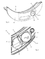
- den Siebeinsatz des Wäschetrockners mit Duftstoff-Behälter,
- Figur 3
- den Siebeinsatz mit geschlossener Öffnung,
- Figur 4
- einen Teilausschnitt des Siebeinsatzes bei entfernter Griffplatte,
- Figur 5
- einen Schnitt durch den Siebeinsatz bei geschlossener Öffnung.
- Die
Figur 1 zeigt in der geschnittenen Seitenansicht eine Trocknungseinrichtung in Form eines Wäschetrockners 1 mit einer in einem Gehäuse 3 drehbar gelagerten Trommel 5. Das Gehäuse 3 ist mit einer Beschickungsöffnung 7 versehen, dahinter liegt die Öffnung 9 der Trommel 5. Der Wäschetrockner 1 verfügt über eine Tür 11, die die Beschickungsöffnung 7 verschließt. Weiter verfügt der Wäschetrockner 1 über ein Gebläse 13 und eine Heizeinrichtung 15, welche zur Erzeugung eines warmen Prozessluftstromes zur Trocknung der Wäschestücke (nicht dargestellt) dient. Der Prozessluftstrom wird über einen Luftkanal 16 geführt, der die Trommel 5 einschließt. Die erwärmte Prozessluft wird im hinteren Bereich 17 in die Trocknertrommel 5 geleitet und nimmt die Feuchtigkeit aus der Wäsche auf. Danach strömt die Prozessluft im verriegelten Zustand der Tür 11 durch einen Spalt 19 zwischen Trommel 5 und Gehäuse 3 im Rand der Beschickungsöffnung 7. Hier ist ein Flusenfilter 21 eingesetzt, der somit einen Teilbereich der Querschnittsfläche der Beschickungsöffnung 7 einnimmt. Der Flusenfilter 21 ist aus einem Siebeinsatz 23 mit mehreren Filterebenen gebildet und stellt einen Teil des Luftkanals 16 dar. Der weitere Aufbau des Siebeinsatzes 23 hinsichtlich seiner Eigenschaft als Flusenfilter 21 ist aus derDE 10 2009 031 097 B4 bekannt und deswegen hier nicht näher beschrieben. Nach dem Flusenfilter 21 passiert die Prozessluft einen Wärmetauscher 24, wo sie abgekühlt und entfeuchtet wird. - Der in den
Figuren 2 und3 als Einzelheit dargestellte Siebeinsatz 23 umfasst ein Siebteil 25, bestehend aus Rahmenbereichen 27, Siebflächen 29 und einer Deckplatte 31 an der Frontseite (siehe auchFigur 4 ), die Siebflächen 29 sind in den Figuren als Freilassungen dargestellt. An der Deckplatte 31 ist eine Griffplatte 33 befestigt, die mit einem Handgriff 35 ausgestattet ist. Des Weiteren ist in denFiguren 2 und3 erkennbar, dass die Frontseite des Siebeinsatzes, d. h. Siebteil 25 und Griffplatte mit einer Öffnung 37 versehen sind, welche einen inFigur 2 gezeigten Duftstoff-Behälter 39 aufnehmen kann. Der Aufbau des Behälters 39 und seine Befestigung in der Öffnung 37 ist aus der früheren europäischen Patentanmeldung mit dem Aktenzeichen12401067.9 Figuren 2 und3 zeigen auch, dass die Öffnung 39 von einem Rand 41 umgeben ist, der aus der Ebene der Griffplatte 33 bzw. der Öffnung 37 nach vorn herausragt. Der Rand 41 ist dazu vorgesehen, eine Anlagefläche für den zylindrischen Behälter 39 zu bilden und diesen dadurch im eingebauten Zustand zu fixieren. Im unteren Bereich ist die Öffnung um eine Aufnahmenut 43 erweitert. An dieser Stelle ist auch der Rand 41 durch eine erste Aussparung 45 unterbrochen. Die Aufnahmenut 43 dient zur formschlüssigen Fixierung eines an den Behälter 39 angeformten Fußes (nicht dargestellt) und bildet mit diesem eine Verdrehsicherung für den Behälter 39. In der Zwei-Uhr-Position der Öffnung 37 ist eine zweite Aussparung 47 im Rand 41 vorhanden, deren Funktion später erklärt ist. In derFigur 3 ist die Öffnung durch eine Verschlusseinrichtung 49 wenigstens annähernd luftdicht versperrt, so dass bei entnommenem Behälter 39 ein Austritt von Prozessluft durch die freibleibende Öffnung 37 verhindert wird. -
Figur 4 zeigt den Siebeinsatz 23 mit entfernter Griffplatte 33, so dass hier nähere Einzelheiten der Verschlusseinrichtung 49 zu erkennen sind. Sie umfasst eine Platte 51, die zwischen der Deckplatte 31 und der Griffplatte 33 schiebbeweglich gelagert ist. Neben einem kreisförmigen Teil 53, welches den eigentlichen Verschluss bildet, sind eine Handhabe 55 und ein angeformter Bereich 57 vorhanden. Die Handhabe 55 ragt in einem Winkel von ca. 90° aus dem kreisförmigen Teil 53. Der angeformte Bereich 57 ist mit einer Rastöffnung 59 versehen. DieFigur 4 zeigt die Platte 51 in ihrer Öffnungsposition. Zum Verschließen der Öffnung 37 wird sie an der Handhabe 55 in der Figur nach links gezogen und dabei um ca. 60° gegen den Uhrzeigersinn gedreht. Die Platte 51 befindet sich dann in der inFigur 3 gezeigten Verschlussposition. Dabei taucht die Handhabe 55 in die erste Aussparung 45 im Bereich der Aufnahmenut 43. Außerdem gleitet die Rastöffnung 59 über einen an die Deckplatte 31 angeformten Rastnippel 61, so dass die Platte 51 in der Verschlussposition fixiert ist. Aus der Zusammenschau derFiguren 2 und4 ist erkennbar, dass die Handhabe 55 in der Öffnungsposition in die zweite Aussparung 47 eintaucht. -
Figur 5 zeigt einen Teilschnitt durch den Siebeinsatz 23 im Bereich der Öffnung 37. Die Platte 51 befindet sich wie inFigur 3 in der Verschlussposition. Es ist erkennbar, dass die Rastöffnung 59 sich über dem Rastnippel 61 befindet und demzufolge die Platte 51 in dieser Position fixiert ist. Durch die Verrastung wird sichergestellt, dass die Platte 51 in der Verschlussposition verbleibt. Dies ist insbesondere wichtig, wenn der Siebeinsatz 23 zur Reinigung aus dem Wäschetrockner 1 entnommen wird. - Bei der vorbeschriebenen Verschlusseinrichtung bedarf es einer Betätigung durch den Benutzer. Es ist auch denkbar, dass die Verschlusseinrichtung 49 nach der der Entnahme des Behälters die Öffnung selbsttätig verschließt. Dies kann durch Ausnutzung der Schwerkraft erreicht werden oder durch einen Federmechanismus. Eine entsprechende Ausführungsform ist in den Zeichnungen nicht dargestellt.
-
- 1
- Wäschetrockner
- 3
- Gehäuse
- 5
- Trommel
- 7
- Beschickungsöffnung (Gehäuse)
- 9
- Öffnung (Trommel)
- 11
- Tür
- 13
- Gebläse
- 15
- Heizeinrichtung
- 16
- Luftkanal
- 17
- hinterer Bereich der Trommel
- 19
- Spalt zwischen Trommel und Gehäuse
- 21
- Flusenfilter
- 23
- Siebeinsatz
- 24
- Wärmetauscher
- 25
- Siebteil
- 27
- Rahmenbereiche
- 29
- Siebflächen
- 31
- Deckplatte
- 33
- Griffplatte
- 35
- Handgriff
- 37
- Öffnung
- 39
- Duftstoff-Behälter
- 41
- Rand
- 43
- Aufnahmenut
- 45
- erste Aussparung (6 Uhr)
- 47
- zweite Aussparung
- 49
- Verschlusseinrichtung
- 51
- Platte
- 53
- kreisförmiger Teil
- 55
- Handhabe
- 57
- angeformter Bereich
- 59
- Rastöffnung
- 61
- Rastnippel
Claims (11)
- Trocknungseinrichtung (1) zum Trocknen von Wäsche mit einem Behandlungsraum zur Aufnahme von Trockengut, mit einer Einrichtung (13) zur Erzeugung eines Prozessluftstroms, und mit einem Luftkanal (16), mit welchem der Prozessluftstrom zum und/oder aus dem Behandlungsraum geführt wird, wobei in dem Luftkanal (16) eine Öffnung (37) angeordnet ist, in die ein Behälter (39) zur Aufnahme und Abgabe eines Duftstoffes einsetzbar ist,
dadurch gekennzeichnet,
dass die Öffnung (37) mittels einer Verschlusseinrichtung (49) bei nicht eingesetztem Behälter (39) verschließbar ist. - Trocknungseinrichtung (1) nach Anspruch 1,
dadurch gekennzeichnet,
dass die Verschlusseinrichtung (49) die Öffnung (37) wenigstens annähernd luftdicht verschließt. - Trocknungseinrichtung (1) nach Anspruch 1 oder 2,
dadurch gekennzeichnet,
dass die Öffnung (37) wenigstens teilweise von einem aus der Öffnungsebene ragenden Rand (41) umgeben ist. - Trocknungseinrichtung (1) nach Anspruch 3,
dadurch gekennzeichnet,
dass der Rand (41) mindestens eine Aussparung (45, 47) aufweist, in die eine an der Verschlusseinrichtung (49) angeordnete Handhabe (55) eintaucht. - Trocknungseinrichtung (1) nach Anspruch 4,
dadurch gekennzeichnet,
dass der Rand (41) zwei Aussparungen (45 und 47) aufweist, wobei die Handhabe (55) bei geöffneter bzw. geschlossener Verschlusseinrichtung (49) jeweils in eine der Aussparungen (45, 47) eintaucht. - Trocknungseinrichtung (1) nach mindestens einem der vorhergehenden Ansprüche,
dadurch gekennzeichnet,
dass die Verschlusseinrichtung (49) in der vollständig geschlossenen Position verrastet ist. - Trocknungseinrichtung (1) nach mindestens einem der vorhergehenden Ansprüche,
dadurch gekennzeichnet,
dass die Verschlusseinrichtung (49) eine schiebbeweglich gelagerte Platte (51) umfasst. - Trocknungseinrichtung (1) nach mindestens einem der vorhergehenden Ansprüche,
dadurch gekennzeichnet,
dass die Öffnung (37) zur Aufnahme des Duftstoff-Behälters in einer Filtereinrichtung (21) angeordnet ist. - Trocknungseinrichtung (1) mit einer in einem Gehäuse (3) drehbar gelagerten Trommel (5), wobei in dem Gehäuse (3) eine durch eine Tür (11) verschließbare Beschickungsöffnung (7) angeordnet ist, nach Anspruch 8,
dadurch gekennzeichnet,
dass die Filtereinrichtung (21) einen Teilbereich der Querschnittsfläche der Beschickungsöffnung (7) einnimmt. - Trocknungseinrichtung (1) nach Anspruch 7 und einem der Ansprüche 8 oder 9,
dadurch gekennzeichnet,
dass die Platte (51) in einem doppelwandigen Bereich der Filtereinrichtung (21) geführt ist. - Trocknungseinrichtung (1) nach mindestens einem der vorhergehenden Ansprüche,
dadurch gekennzeichnet,
dass die Verschlusseinrichtung (49) nach der der Entnahme des Behälters (39) die Öffnung (37) selbsttätig verschließt.
Priority Applications (1)
| Application Number | Priority Date | Filing Date | Title |
|---|---|---|---|
| EP12401105.7A EP2669423B1 (de) | 2012-05-31 | 2012-05-31 | Trocknungseinrichtung zum Trocknen von Wäsche mit einem Behälter zur Aufnahme und Abgabe eines Duftstoffes |
Applications Claiming Priority (1)
| Application Number | Priority Date | Filing Date | Title |
|---|---|---|---|
| EP12401105.7A EP2669423B1 (de) | 2012-05-31 | 2012-05-31 | Trocknungseinrichtung zum Trocknen von Wäsche mit einem Behälter zur Aufnahme und Abgabe eines Duftstoffes |
Publications (2)
| Publication Number | Publication Date |
|---|---|
| EP2669423A1 true EP2669423A1 (de) | 2013-12-04 |
| EP2669423B1 EP2669423B1 (de) | 2016-03-02 |
Family
ID=46354123
Family Applications (1)
| Application Number | Title | Priority Date | Filing Date |
|---|---|---|---|
| EP12401105.7A Active EP2669423B1 (de) | 2012-05-31 | 2012-05-31 | Trocknungseinrichtung zum Trocknen von Wäsche mit einem Behälter zur Aufnahme und Abgabe eines Duftstoffes |
Country Status (1)
| Country | Link |
|---|---|
| EP (1) | EP2669423B1 (de) |
Cited By (8)
| Publication number | Priority date | Publication date | Assignee | Title |
|---|---|---|---|---|
| WO2016034302A1 (en) * | 2014-09-05 | 2016-03-10 | Arcelik Anonim Sirketi | A dryer comprising a fragrance source |
| WO2016034304A1 (en) * | 2014-09-05 | 2016-03-10 | Arcelik Anonim Sirketi | A dryer comprising a fragrance source |
| WO2016034303A1 (en) | 2014-09-05 | 2016-03-10 | Arcelik Anonim Sirketi | A dryer comprising a fragrance source |
| DE102014115695A1 (de) | 2014-10-29 | 2016-05-04 | Miele & Cie. Kg | Trockner mit einem Behälter zur Abgabe eines Duftstoffes |
| EP3112526A1 (de) * | 2015-07-01 | 2017-01-04 | Indesit Company S.p.A. | Trägervorrichtung für luftfilter für trockner oder waschtrockner, luftfilter für trockner oder waschtrockner mit besagter trägervorrichtung und trockner oder waschtrockner mit besagtem filter |
| CN107916550A (zh) * | 2016-10-11 | 2018-04-17 | 青岛海尔洗衣机有限公司 | 一种带有挡板的干衣机 |
| CN110093764A (zh) * | 2018-01-31 | 2019-08-06 | 青岛海尔滚筒洗衣机有限公司 | 一种干衣机的冷凝器及具有该冷凝器的干衣机 |
| CN113684655A (zh) * | 2021-08-30 | 2021-11-23 | 无锡小天鹅电器有限公司 | 衣物处理装置的进风格栅以及衣物处理装置 |
Families Citing this family (2)
| Publication number | Priority date | Publication date | Assignee | Title |
|---|---|---|---|---|
| DE102018118178A1 (de) * | 2018-07-27 | 2020-01-30 | Miele & Cie. Kg | Behälter zur Aufnahme und Abgabe eines Duftstoffs in den Behandlungsraum eines Haushaltsgeräts sowie Haushaltsgerät mit einem derartigen Behälter |
| DE102018120954B4 (de) * | 2018-08-28 | 2025-10-23 | Miele & Cie. Kg | Programmgesteuerter Wäschetrockner |
Citations (10)
| Publication number | Priority date | Publication date | Assignee | Title |
|---|---|---|---|---|
| JPH034899A (ja) * | 1989-05-31 | 1991-01-10 | Sanyo Electric Co Ltd | 除湿型衣類乾燥機 |
| JPH0938388A (ja) * | 1995-08-03 | 1997-02-10 | Matsushita Electric Ind Co Ltd | 衣類乾燥機 |
| DE29922439U1 (de) * | 1998-12-23 | 2000-03-02 | Electrolux Zanussi S.P.A., Pordenone | Trockner mit drehender Trommel |
| EP1240106A1 (de) | 1999-11-30 | 2002-09-18 | Agne Rubertsson | Verfahren zur reinigung von objekten durch eine erwärmte flüssigkeit und anlage zur durchführung dieses verfahrens |
| WO2002090853A1 (en) * | 2001-05-10 | 2002-11-14 | Benny Mizrahi | Clothes dryer |
| KR20070007548A (ko) | 2005-07-11 | 2007-01-16 | 엘지전자 주식회사 | 건조기의 필터 구조 |
| DE102005055180A1 (de) * | 2005-11-18 | 2007-05-24 | BSH Bosch und Siemens Hausgeräte GmbH | Flusenfiltereinrichtung |
| WO2008072876A1 (en) * | 2006-12-11 | 2008-06-19 | Lg Electronics Inc. | Washing/drying machine |
| DE102009031097B4 (de) | 2009-06-29 | 2011-03-24 | Miele & Cie. Kg | Wäschetrockner |
| EP2431516A1 (de) | 2010-09-21 | 2012-03-21 | Miele & Cie. KG | Beduftungseinrichtung für eine Wäschebehandlungsmaschine |
-
2012
- 2012-05-31 EP EP12401105.7A patent/EP2669423B1/de active Active
Patent Citations (10)
| Publication number | Priority date | Publication date | Assignee | Title |
|---|---|---|---|---|
| JPH034899A (ja) * | 1989-05-31 | 1991-01-10 | Sanyo Electric Co Ltd | 除湿型衣類乾燥機 |
| JPH0938388A (ja) * | 1995-08-03 | 1997-02-10 | Matsushita Electric Ind Co Ltd | 衣類乾燥機 |
| DE29922439U1 (de) * | 1998-12-23 | 2000-03-02 | Electrolux Zanussi S.P.A., Pordenone | Trockner mit drehender Trommel |
| EP1240106A1 (de) | 1999-11-30 | 2002-09-18 | Agne Rubertsson | Verfahren zur reinigung von objekten durch eine erwärmte flüssigkeit und anlage zur durchführung dieses verfahrens |
| WO2002090853A1 (en) * | 2001-05-10 | 2002-11-14 | Benny Mizrahi | Clothes dryer |
| KR20070007548A (ko) | 2005-07-11 | 2007-01-16 | 엘지전자 주식회사 | 건조기의 필터 구조 |
| DE102005055180A1 (de) * | 2005-11-18 | 2007-05-24 | BSH Bosch und Siemens Hausgeräte GmbH | Flusenfiltereinrichtung |
| WO2008072876A1 (en) * | 2006-12-11 | 2008-06-19 | Lg Electronics Inc. | Washing/drying machine |
| DE102009031097B4 (de) | 2009-06-29 | 2011-03-24 | Miele & Cie. Kg | Wäschetrockner |
| EP2431516A1 (de) | 2010-09-21 | 2012-03-21 | Miele & Cie. KG | Beduftungseinrichtung für eine Wäschebehandlungsmaschine |
Cited By (10)
| Publication number | Priority date | Publication date | Assignee | Title |
|---|---|---|---|---|
| WO2016034302A1 (en) * | 2014-09-05 | 2016-03-10 | Arcelik Anonim Sirketi | A dryer comprising a fragrance source |
| WO2016034304A1 (en) * | 2014-09-05 | 2016-03-10 | Arcelik Anonim Sirketi | A dryer comprising a fragrance source |
| WO2016034303A1 (en) | 2014-09-05 | 2016-03-10 | Arcelik Anonim Sirketi | A dryer comprising a fragrance source |
| DE102014115695A1 (de) | 2014-10-29 | 2016-05-04 | Miele & Cie. Kg | Trockner mit einem Behälter zur Abgabe eines Duftstoffes |
| EP3015589A1 (de) | 2014-10-29 | 2016-05-04 | Miele & Cie. KG | Trockner mit einem behälter zur abgabe eines duftstoffes |
| DE102014115695B4 (de) | 2014-10-29 | 2018-11-22 | Miele & Cie. Kg | Trockner mit einem Behälter zur Abgabe eines Duftstoffes |
| EP3112526A1 (de) * | 2015-07-01 | 2017-01-04 | Indesit Company S.p.A. | Trägervorrichtung für luftfilter für trockner oder waschtrockner, luftfilter für trockner oder waschtrockner mit besagter trägervorrichtung und trockner oder waschtrockner mit besagtem filter |
| CN107916550A (zh) * | 2016-10-11 | 2018-04-17 | 青岛海尔洗衣机有限公司 | 一种带有挡板的干衣机 |
| CN110093764A (zh) * | 2018-01-31 | 2019-08-06 | 青岛海尔滚筒洗衣机有限公司 | 一种干衣机的冷凝器及具有该冷凝器的干衣机 |
| CN113684655A (zh) * | 2021-08-30 | 2021-11-23 | 无锡小天鹅电器有限公司 | 衣物处理装置的进风格栅以及衣物处理装置 |
Also Published As
| Publication number | Publication date |
|---|---|
| EP2669423B1 (de) | 2016-03-02 |
Similar Documents
| Publication | Publication Date | Title |
|---|---|---|
| EP2669423B1 (de) | Trocknungseinrichtung zum Trocknen von Wäsche mit einem Behälter zur Aufnahme und Abgabe eines Duftstoffes | |
| EP2492389B1 (de) | Wäschetrockner mit entsorgbarer Flusenfilter-Vorrichtung | |
| EP2669422B1 (de) | Trocknungseinrichtung zum Trocknen von Wäsche mit einem Behälter zur Aufnahme und Abgabe eines Duftstoffes | |
| EP1098028A2 (de) | Wäschetrockner mit einem selbstreinigenden Flusenfilter | |
| DE102007012071A1 (de) | Wäschtrockner mit verbesserter Flusenbeseitigung sowie Verfahren zu seinem Betrieb | |
| EP2210975B1 (de) | Verfahren zur Abgabe eines Duftstoffes während des Trocknungsprozesses in einem Wäschetrockner | |
| EP2392723B1 (de) | Wäschetrockner mit einem Filter und Verfahren zum Betrieb eines Wäschetrockners | |
| DE102008054548A1 (de) | Trockner mit Umluftanteil sowie Verfahren zu seinem Betrieb | |
| DE102007049959A1 (de) | Flusenfiltervorrichtung und Hausgerät mit einer derartigen Flusenfiltervorrichtung | |
| EP2371258A2 (de) | Geschirrspüler mit Türspaltlüftung | |
| EP2476960B1 (de) | Umschaltvorrichtung für eine Dunstabzugshaube zum Umschalten zwischen Umluft- und Abluftbetrieb | |
| EP2038471A1 (de) | Klappe für ein haushaltgerät | |
| EP2855759A1 (de) | Aufnahmevorrichtung für einen entnehmbaren filter eines haushaltsgeräts | |
| EP2589698A1 (de) | Wäschebehandlungsmaschine wie Waschmaschine oder Wäschetrockner | |
| DE102009028184A1 (de) | Wasserführendes Hausgerät mit einer Schale | |
| DE102014111249A1 (de) | Staubfilterbeutel für einen Staubsauger sowie Staubsauger mit einem Staubfilterbeutel | |
| DE102018120954B4 (de) | Programmgesteuerter Wäschetrockner | |
| DE102014115695B4 (de) | Trockner mit einem Behälter zur Abgabe eines Duftstoffes | |
| DE19745091A1 (de) | Flusenfilter-Einrichtung für einen elektrischen Wäschetrockner | |
| EP2210976B1 (de) | Wäschebehandlungsmaschine, wie beispielsweise ein Wäschetrockner | |
| EP2664706B1 (de) | Wäschetrockner | |
| EP0374411B1 (de) | Trommel-Wäschetrockner mit einem Wäscheabweiser | |
| DE102014105327B4 (de) | Wäschetrockner | |
| EP3488043B1 (de) | Wäschebehandlungsgerät | |
| DE102020214557A1 (de) | Tür für ein Wäschebehandlungsgerät, insbesondere für einen Wäschetrockner oder Waschtrockner |
Legal Events
| Date | Code | Title | Description |
|---|---|---|---|
| PUAI | Public reference made under article 153(3) epc to a published international application that has entered the european phase |
Free format text: ORIGINAL CODE: 0009012 |
|
| AK | Designated contracting states |
Kind code of ref document: A1 Designated state(s): AL AT BE BG CH CY CZ DE DK EE ES FI FR GB GR HR HU IE IS IT LI LT LU LV MC MK MT NL NO PL PT RO RS SE SI SK SM TR |
|
| AX | Request for extension of the european patent |
Extension state: BA ME |
|
| 17P | Request for examination filed |
Effective date: 20140604 |
|
| RBV | Designated contracting states (corrected) |
Designated state(s): AL AT BE BG CH CY CZ DE DK EE ES FI FR GB GR HR HU IE IS IT LI LT LU LV MC MK MT NL NO PL PT RO RS SE SI SK SM TR |
|
| GRAP | Despatch of communication of intention to grant a patent |
Free format text: ORIGINAL CODE: EPIDOSNIGR1 |
|
| RIC1 | Information provided on ipc code assigned before grant |
Ipc: D06F 58/22 20060101ALI20150729BHEP Ipc: D06F 58/20 20060101AFI20150729BHEP |
|
| INTG | Intention to grant announced |
Effective date: 20150903 |
|
| GRAS | Grant fee paid |
Free format text: ORIGINAL CODE: EPIDOSNIGR3 |
|
| GRAA | (expected) grant |
Free format text: ORIGINAL CODE: 0009210 |
|
| AK | Designated contracting states |
Kind code of ref document: B1 Designated state(s): AL AT BE BG CH CY CZ DE DK EE ES FI FR GB GR HR HU IE IS IT LI LT LU LV MC MK MT NL NO PL PT RO RS SE SI SK SM TR |
|
| REG | Reference to a national code |
Ref country code: GB Ref legal event code: FG4D Free format text: NOT ENGLISH |
|
| REG | Reference to a national code |
Ref country code: AT Ref legal event code: REF Ref document number: 778145 Country of ref document: AT Kind code of ref document: T Effective date: 20160315 Ref country code: CH Ref legal event code: EP |
|
| REG | Reference to a national code |
Ref country code: IE Ref legal event code: FG4D Free format text: LANGUAGE OF EP DOCUMENT: GERMAN |
|
| REG | Reference to a national code |
Ref country code: DE Ref legal event code: R096 Ref document number: 502012006118 Country of ref document: DE |
|
| REG | Reference to a national code |
Ref country code: NL Ref legal event code: FP |
|
| REG | Reference to a national code |
Ref country code: FR Ref legal event code: PLFP Year of fee payment: 5 |
|
| REG | Reference to a national code |
Ref country code: LT Ref legal event code: MG4D |
|
| PG25 | Lapsed in a contracting state [announced via postgrant information from national office to epo] |
Ref country code: NO Free format text: LAPSE BECAUSE OF FAILURE TO SUBMIT A TRANSLATION OF THE DESCRIPTION OR TO PAY THE FEE WITHIN THE PRESCRIBED TIME-LIMIT Effective date: 20160602 Ref country code: GR Free format text: LAPSE BECAUSE OF FAILURE TO SUBMIT A TRANSLATION OF THE DESCRIPTION OR TO PAY THE FEE WITHIN THE PRESCRIBED TIME-LIMIT Effective date: 20160603 Ref country code: HR Free format text: LAPSE BECAUSE OF FAILURE TO SUBMIT A TRANSLATION OF THE DESCRIPTION OR TO PAY THE FEE WITHIN THE PRESCRIBED TIME-LIMIT Effective date: 20160302 Ref country code: FI Free format text: LAPSE BECAUSE OF FAILURE TO SUBMIT A TRANSLATION OF THE DESCRIPTION OR TO PAY THE FEE WITHIN THE PRESCRIBED TIME-LIMIT Effective date: 20160302 Ref country code: ES Free format text: LAPSE BECAUSE OF FAILURE TO SUBMIT A TRANSLATION OF THE DESCRIPTION OR TO PAY THE FEE WITHIN THE PRESCRIBED TIME-LIMIT Effective date: 20160302 |
|
| PG25 | Lapsed in a contracting state [announced via postgrant information from national office to epo] |
Ref country code: LT Free format text: LAPSE BECAUSE OF FAILURE TO SUBMIT A TRANSLATION OF THE DESCRIPTION OR TO PAY THE FEE WITHIN THE PRESCRIBED TIME-LIMIT Effective date: 20160302 Ref country code: RS Free format text: LAPSE BECAUSE OF FAILURE TO SUBMIT A TRANSLATION OF THE DESCRIPTION OR TO PAY THE FEE WITHIN THE PRESCRIBED TIME-LIMIT Effective date: 20160302 Ref country code: SE Free format text: LAPSE BECAUSE OF FAILURE TO SUBMIT A TRANSLATION OF THE DESCRIPTION OR TO PAY THE FEE WITHIN THE PRESCRIBED TIME-LIMIT Effective date: 20160302 Ref country code: BE Free format text: LAPSE BECAUSE OF NON-PAYMENT OF DUE FEES Effective date: 20160531 Ref country code: LV Free format text: LAPSE BECAUSE OF FAILURE TO SUBMIT A TRANSLATION OF THE DESCRIPTION OR TO PAY THE FEE WITHIN THE PRESCRIBED TIME-LIMIT Effective date: 20160302 Ref country code: PL Free format text: LAPSE BECAUSE OF FAILURE TO SUBMIT A TRANSLATION OF THE DESCRIPTION OR TO PAY THE FEE WITHIN THE PRESCRIBED TIME-LIMIT Effective date: 20160302 |
|
| PG25 | Lapsed in a contracting state [announced via postgrant information from national office to epo] |
Ref country code: IS Free format text: LAPSE BECAUSE OF FAILURE TO SUBMIT A TRANSLATION OF THE DESCRIPTION OR TO PAY THE FEE WITHIN THE PRESCRIBED TIME-LIMIT Effective date: 20160702 Ref country code: EE Free format text: LAPSE BECAUSE OF FAILURE TO SUBMIT A TRANSLATION OF THE DESCRIPTION OR TO PAY THE FEE WITHIN THE PRESCRIBED TIME-LIMIT Effective date: 20160302 |
|
| PG25 | Lapsed in a contracting state [announced via postgrant information from national office to epo] |
Ref country code: RO Free format text: LAPSE BECAUSE OF FAILURE TO SUBMIT A TRANSLATION OF THE DESCRIPTION OR TO PAY THE FEE WITHIN THE PRESCRIBED TIME-LIMIT Effective date: 20160302 Ref country code: PT Free format text: LAPSE BECAUSE OF FAILURE TO SUBMIT A TRANSLATION OF THE DESCRIPTION OR TO PAY THE FEE WITHIN THE PRESCRIBED TIME-LIMIT Effective date: 20160704 Ref country code: CZ Free format text: LAPSE BECAUSE OF FAILURE TO SUBMIT A TRANSLATION OF THE DESCRIPTION OR TO PAY THE FEE WITHIN THE PRESCRIBED TIME-LIMIT Effective date: 20160302 Ref country code: SK Free format text: LAPSE BECAUSE OF FAILURE TO SUBMIT A TRANSLATION OF THE DESCRIPTION OR TO PAY THE FEE WITHIN THE PRESCRIBED TIME-LIMIT Effective date: 20160302 Ref country code: SM Free format text: LAPSE BECAUSE OF FAILURE TO SUBMIT A TRANSLATION OF THE DESCRIPTION OR TO PAY THE FEE WITHIN THE PRESCRIBED TIME-LIMIT Effective date: 20160302 |
|
| REG | Reference to a national code |
Ref country code: DE Ref legal event code: R097 Ref document number: 502012006118 Country of ref document: DE |
|
| PG25 | Lapsed in a contracting state [announced via postgrant information from national office to epo] |
Ref country code: LU Free format text: LAPSE BECAUSE OF FAILURE TO SUBMIT A TRANSLATION OF THE DESCRIPTION OR TO PAY THE FEE WITHIN THE PRESCRIBED TIME-LIMIT Effective date: 20160531 |
|
| REG | Reference to a national code |
Ref country code: CH Ref legal event code: PL |
|
| PLBE | No opposition filed within time limit |
Free format text: ORIGINAL CODE: 0009261 |
|
| STAA | Information on the status of an ep patent application or granted ep patent |
Free format text: STATUS: NO OPPOSITION FILED WITHIN TIME LIMIT |
|
| PG25 | Lapsed in a contracting state [announced via postgrant information from national office to epo] |
Ref country code: LI Free format text: LAPSE BECAUSE OF NON-PAYMENT OF DUE FEES Effective date: 20160531 Ref country code: DK Free format text: LAPSE BECAUSE OF FAILURE TO SUBMIT A TRANSLATION OF THE DESCRIPTION OR TO PAY THE FEE WITHIN THE PRESCRIBED TIME-LIMIT Effective date: 20160302 Ref country code: CH Free format text: LAPSE BECAUSE OF NON-PAYMENT OF DUE FEES Effective date: 20160531 |
|
| 26N | No opposition filed |
Effective date: 20161205 |
|
| REG | Reference to a national code |
Ref country code: IE Ref legal event code: MM4A |
|
| PG25 | Lapsed in a contracting state [announced via postgrant information from national office to epo] |
Ref country code: SI Free format text: LAPSE BECAUSE OF FAILURE TO SUBMIT A TRANSLATION OF THE DESCRIPTION OR TO PAY THE FEE WITHIN THE PRESCRIBED TIME-LIMIT Effective date: 20160302 Ref country code: BG Free format text: LAPSE BECAUSE OF FAILURE TO SUBMIT A TRANSLATION OF THE DESCRIPTION OR TO PAY THE FEE WITHIN THE PRESCRIBED TIME-LIMIT Effective date: 20160602 |
|
| REG | Reference to a national code |
Ref country code: FR Ref legal event code: PLFP Year of fee payment: 6 |
|
| PG25 | Lapsed in a contracting state [announced via postgrant information from national office to epo] |
Ref country code: IE Free format text: LAPSE BECAUSE OF NON-PAYMENT OF DUE FEES Effective date: 20160531 |
|
| REG | Reference to a national code |
Ref country code: FR Ref legal event code: PLFP Year of fee payment: 7 |
|
| PG25 | Lapsed in a contracting state [announced via postgrant information from national office to epo] |
Ref country code: CY Free format text: LAPSE BECAUSE OF FAILURE TO SUBMIT A TRANSLATION OF THE DESCRIPTION OR TO PAY THE FEE WITHIN THE PRESCRIBED TIME-LIMIT Effective date: 20160302 Ref country code: HU Free format text: LAPSE BECAUSE OF FAILURE TO SUBMIT A TRANSLATION OF THE DESCRIPTION OR TO PAY THE FEE WITHIN THE PRESCRIBED TIME-LIMIT; INVALID AB INITIO Effective date: 20120531 |
|
| PG25 | Lapsed in a contracting state [announced via postgrant information from national office to epo] |
Ref country code: MC Free format text: LAPSE BECAUSE OF FAILURE TO SUBMIT A TRANSLATION OF THE DESCRIPTION OR TO PAY THE FEE WITHIN THE PRESCRIBED TIME-LIMIT Effective date: 20160302 Ref country code: TR Free format text: LAPSE BECAUSE OF FAILURE TO SUBMIT A TRANSLATION OF THE DESCRIPTION OR TO PAY THE FEE WITHIN THE PRESCRIBED TIME-LIMIT Effective date: 20160302 Ref country code: MT Free format text: LAPSE BECAUSE OF FAILURE TO SUBMIT A TRANSLATION OF THE DESCRIPTION OR TO PAY THE FEE WITHIN THE PRESCRIBED TIME-LIMIT Effective date: 20160302 Ref country code: MK Free format text: LAPSE BECAUSE OF FAILURE TO SUBMIT A TRANSLATION OF THE DESCRIPTION OR TO PAY THE FEE WITHIN THE PRESCRIBED TIME-LIMIT Effective date: 20160302 |
|
| REG | Reference to a national code |
Ref country code: AT Ref legal event code: MM01 Ref document number: 778145 Country of ref document: AT Kind code of ref document: T Effective date: 20170531 |
|
| PG25 | Lapsed in a contracting state [announced via postgrant information from national office to epo] |
Ref country code: AT Free format text: LAPSE BECAUSE OF NON-PAYMENT OF DUE FEES Effective date: 20170531 |
|
| PG25 | Lapsed in a contracting state [announced via postgrant information from national office to epo] |
Ref country code: AL Free format text: LAPSE BECAUSE OF FAILURE TO SUBMIT A TRANSLATION OF THE DESCRIPTION OR TO PAY THE FEE WITHIN THE PRESCRIBED TIME-LIMIT Effective date: 20160302 |
|
| REG | Reference to a national code |
Ref country code: DE Ref legal event code: R084 Ref document number: 502012006118 Country of ref document: DE |
|
| P01 | Opt-out of the competence of the unified patent court (upc) registered |
Effective date: 20230529 |
|
| PGFP | Annual fee paid to national office [announced via postgrant information from national office to epo] |
Ref country code: NL Payment date: 20240527 Year of fee payment: 13 |
|
| PGFP | Annual fee paid to national office [announced via postgrant information from national office to epo] |
Ref country code: IT Payment date: 20240524 Year of fee payment: 13 |
|
| REG | Reference to a national code |
Ref country code: NL Ref legal event code: MM Effective date: 20250601 |
|
| PG25 | Lapsed in a contracting state [announced via postgrant information from national office to epo] |
Ref country code: NL Free format text: LAPSE BECAUSE OF NON-PAYMENT OF DUE FEES Effective date: 20250601 |
|
| PGFP | Annual fee paid to national office [announced via postgrant information from national office to epo] |
Ref country code: GB Payment date: 20260313 Year of fee payment: 15 |
|
| PG25 | Lapsed in a contracting state [announced via postgrant information from national office to epo] |
Ref country code: IT Free format text: LAPSE BECAUSE OF NON-PAYMENT OF DUE FEES Effective date: 20250531 |
|
| PGFP | Annual fee paid to national office [announced via postgrant information from national office to epo] |
Ref country code: DE Payment date: 20260531 Year of fee payment: 15 |
|
| PGFP | Annual fee paid to national office [announced via postgrant information from national office to epo] |
Ref country code: FR Payment date: 20260521 Year of fee payment: 15 |