EP2668543B1 - Steuerungssystem für eine elektrochrome vorrichtung - Google Patents
Steuerungssystem für eine elektrochrome vorrichtung Download PDFInfo
- Publication number
- EP2668543B1 EP2668543B1 EP12704168.9A EP12704168A EP2668543B1 EP 2668543 B1 EP2668543 B1 EP 2668543B1 EP 12704168 A EP12704168 A EP 12704168A EP 2668543 B1 EP2668543 B1 EP 2668543B1
- Authority
- EP
- European Patent Office
- Prior art keywords
- module
- electronics module
- electrochromic glazing
- photovoltaic
- electrochromic
- Prior art date
- Legal status (The legal status is an assumption and is not a legal conclusion. Google has not performed a legal analysis and makes no representation as to the accuracy of the status listed.)
- Active
Links
Images













Classifications
-
- G—PHYSICS
- G02—OPTICS
- G02F—OPTICAL DEVICES OR ARRANGEMENTS FOR THE CONTROL OF LIGHT BY MODIFICATION OF THE OPTICAL PROPERTIES OF THE MEDIA OF THE ELEMENTS INVOLVED THEREIN; NON-LINEAR OPTICS; FREQUENCY-CHANGING OF LIGHT; OPTICAL LOGIC ELEMENTS; OPTICAL ANALOGUE/DIGITAL CONVERTERS
- G02F1/00—Devices or arrangements for the control of the intensity, colour, phase, polarisation or direction of light arriving from an independent light source, e.g. switching, gating or modulating; Non-linear optics
- G02F1/01—Devices or arrangements for the control of the intensity, colour, phase, polarisation or direction of light arriving from an independent light source, e.g. switching, gating or modulating; Non-linear optics for the control of the intensity, phase, polarisation or colour
- G02F1/15—Devices or arrangements for the control of the intensity, colour, phase, polarisation or direction of light arriving from an independent light source, e.g. switching, gating or modulating; Non-linear optics for the control of the intensity, phase, polarisation or colour based on an electrochromic effect
- G02F1/153—Constructional details
- G02F1/157—Structural association of cells with optical devices, e.g. reflectors or illuminating devices
-
- E—FIXED CONSTRUCTIONS
- E04—BUILDING
- E04B—GENERAL BUILDING CONSTRUCTIONS; WALLS, e.g. PARTITIONS; ROOFS; FLOORS; CEILINGS; INSULATION OR OTHER PROTECTION OF BUILDINGS
- E04B2/00—Walls, e.g. partitions, for buildings; Wall construction with regard to insulation; Connections specially adapted to walls
- E04B2/88—Curtain walls
-
- G—PHYSICS
- G02—OPTICS
- G02F—OPTICAL DEVICES OR ARRANGEMENTS FOR THE CONTROL OF LIGHT BY MODIFICATION OF THE OPTICAL PROPERTIES OF THE MEDIA OF THE ELEMENTS INVOLVED THEREIN; NON-LINEAR OPTICS; FREQUENCY-CHANGING OF LIGHT; OPTICAL LOGIC ELEMENTS; OPTICAL ANALOGUE/DIGITAL CONVERTERS
- G02F1/00—Devices or arrangements for the control of the intensity, colour, phase, polarisation or direction of light arriving from an independent light source, e.g. switching, gating or modulating; Non-linear optics
- G02F1/01—Devices or arrangements for the control of the intensity, colour, phase, polarisation or direction of light arriving from an independent light source, e.g. switching, gating or modulating; Non-linear optics for the control of the intensity, phase, polarisation or colour
- G02F1/13—Devices or arrangements for the control of the intensity, colour, phase, polarisation or direction of light arriving from an independent light source, e.g. switching, gating or modulating; Non-linear optics for the control of the intensity, phase, polarisation or colour based on liquid crystals, e.g. single liquid crystal display cells
- G02F1/133—Constructional arrangements; Operation of liquid crystal cells; Circuit arrangements
- G02F1/13306—Circuit arrangements or driving methods for the control of single liquid crystal cells
- G02F1/13324—Circuits comprising solar cells
-
- G—PHYSICS
- G02—OPTICS
- G02F—OPTICAL DEVICES OR ARRANGEMENTS FOR THE CONTROL OF LIGHT BY MODIFICATION OF THE OPTICAL PROPERTIES OF THE MEDIA OF THE ELEMENTS INVOLVED THEREIN; NON-LINEAR OPTICS; FREQUENCY-CHANGING OF LIGHT; OPTICAL LOGIC ELEMENTS; OPTICAL ANALOGUE/DIGITAL CONVERTERS
- G02F1/00—Devices or arrangements for the control of the intensity, colour, phase, polarisation or direction of light arriving from an independent light source, e.g. switching, gating or modulating; Non-linear optics
- G02F1/01—Devices or arrangements for the control of the intensity, colour, phase, polarisation or direction of light arriving from an independent light source, e.g. switching, gating or modulating; Non-linear optics for the control of the intensity, phase, polarisation or colour
- G02F1/15—Devices or arrangements for the control of the intensity, colour, phase, polarisation or direction of light arriving from an independent light source, e.g. switching, gating or modulating; Non-linear optics for the control of the intensity, phase, polarisation or colour based on an electrochromic effect
- G02F1/163—Operation of electrochromic cells, e.g. electrodeposition cells; Circuit arrangements therefor
Definitions
- Electrochromic glazings include electrochromic materials that are known to change their optical properties, such as coloration, in response to the application of an electrical potential, thereby making the device more or less transparent or more or less reflective.
- IT MI 910 453 A1 relates to a ventilated frame for the air conditioning of buildings.
- the ventilated frame includes a proper frame with double glazing, within which an electrochromatic device is located. It is possible to adjust the transparency of the electrochromatic device automatically by means of external photovoltaic cells. The control of the transparency is provided automatically as a function of incident solar radiation. The automatic control is determined an electronic control unit.
- US 6,055,089 relates to a photovoltaic powering and control system for electrochromic windows. An insulated glass unit comprising two glass plates is provided.
- An array of low profile photovoltaic cells is arranged on the inside surface of a glass plate.
- a remote control system for controlling the device is provided for controlling the connection between the photovoltaic cells and the electrochromic coating.
- US 2010/0188057 relates to a green technology system.
- An Isolated Glass Unit has a solar panel and an EC panel. The solar panel and a Switch Mode Power Supply provide the solar power energy to the green technology system.
- JP S58 131021 U relates to a dimming device involving a solar cell which supplies electric power to a light controlling body and which further includes a light controlling body drive circuit.
- the light controlling body involves an electrochromic substance.
- JP S59 191017 A describes a window glass including a variable member which becomes opaque from transparent by an electric conduction to electrodes.
- a power source circuit E1 of a battery and a power source circuit E2 of a solar battery are placed symmetrically against a changeover switch SW2, so as to be switchable to positive and negative, this changeover switch SW2 is connected to a changeover switch SW1, and a contact of SW1 is provided on an electric conduction circuit to the electrodes so that the electrodes convert the polarity by switching positive and negative.
- US 5040585 A describes a motor driven screen apparatus.
- a motor-driven blind is disposed within a double-glazed sliding door unit having an outer glass plate and an inner glass plate spaced from each other.
- a solar cell panel is disposed at the lowest portion on the inside of the outer glass plate and is mounted at an inclination angle so that its lower edge portion is positioned on a gasket and its upper edge portion extends toward the inner glass plate.
- Typical prior art electrochromic devices include a counter electrode layer, an electrochromic material layer which is deposited substantially parallel to the counter electrode layer, and an ionically conductive layer separating the counter electrode layer from the electrochromic layer respectively.
- two transparent conductive layers are substantially parallel to and in contact with the counter electrode layer and the electrochromic layer.
- Materials for making the counter electrode layer, the electrochromic material layer, the ionically conductive layer and the conductive layers are known and described, for example, in United States Patent Publication No. 2008/0169185 , and desirably are substantially transparent oxides or nitrides.
- an electrical potential is applied across the layered structure of the electrochromic device, such as by connecting the respective conductive layers to a low voltage electrical source, ions, such as Li+ ions stored in the counter electrode layer, flow from the counter electrode layer, through the ion conductor layer and to the electrochromic layer.
- electrons flow from the counter electrode layer, around an external circuit including a low voltage electrical source, to the electrochromic layer so as to maintain charge neutrality in the counter electrode layer and the electrochromic layer.
- the transfer of ions and electrons to the electrochromic layer causes the optical characteristics of the electrochromic layer, and optionally the counter electrode layer in a complementary EC device, to change, thereby changing the coloration and, thus, the transparency of the electrochromic device
- One aspect of the invention is a device for modulating the transmission of light from a light source, comprising an electrochromic glazing having light transmissivity that is variable in response to an electrical current; at least one photovoltaic module electrically connected to the electrochromic glazing for providing the electrical current to the electrochromic glazing in response to light from the light source incident on the photovoltaic module; and an electronics module in communication with either of the photovoltaic module or the electrochromic glazing.
- the electronics module is in wireless communication with a building automation system.
- the photovoltaic module is mounted to an exterior surface of the electrochromic glazing
- the photovoltaic module comprises a photovoltaic material which may be an interior or exterior layer in a glass laminate.
- electrochromic glazing is a laminate of at least two glass panes.
- the electronics module is mounted to an interior or exterior surface of the electrochromic glazing or within an insulated glazing unit.
- the electronics module is mounted adjacent to the electrochromic glazing on an interior or exterior building frame-work.
- the photovoltaic module and the electronics module are mounted at different locations.
- the photovoltaic module is located on an exterior surface, and the electronics module is located inside or protruding into a framing system, and wherein the electronics module is in wireless communication with a building automation system.
- the photovoltaic module is located on an exterior surface, and the electronics module is located in an interior frame-work, and wherein the electronics module is in wireless communication with a building automation system.
- the photovoltaic module and the electronics module are combined into a single unit. In another embodiment, the combined photovoltaic and electronics module have a thickness less than about 10mm.
- the electronics module responds to solar intensity such that the electrochromic glazing tints or colors proportionally to available sunlight.
- the electronics modules comprises control logic means.
- control logic means monitors available energy from the photovoltaic module.
- the device further comprises a battery.
- the electrochromic glazing or IGU contains a privacy or anti-glare coating.
- the IGU comprises two EC glazings.
- electronics module is in wireless communication with a building automation system.
- the electronics module comprises a photovoltaic module and a resistor wired in parallel with an electrochromic glazing wiring.
- the photovoltaic module is connected to the electronics module through an electrical feed-through. In another embodiment, the photovoltaic module is coupled to the electronics module via a wireless energy transfer means.
- the photovoltaic module is mounted to an exterior surface of the electrochromic glazing.
- the electronics module is mounted to an interior or exterior surface of the electrochromic glazing or within an insulated glazing unit.
- the electronics module is mounted adjacent to the electrochromic glazing on an interior or exterior building frame-work.
- the photovoltaic module and the electronics module are mounted at different locations.
- the photovoltaic module is located on an exterior surface, and the electronics module is located inside or protruding into a framing system, and wherein the electronics module is in wireless communication with a building automation system.
- the photovoltaic module and the electronics module are combined into a single unit. In another embodiment, the combined photovoltaic and electronics module has a thickness less than about 10mm.
- the electronics module responds to solar intensity such that the electrochromic glazing tints or colors proportionally to available sunlight.
- the electronics modules comprises control logic means.
- control logic means monitors available energy from the photovoltaic module.
- the device further comprises a battery.
- the electronics module comprises a photovoltaic module and a resistor wired in parallel with an electrochromic glazing wiring.
- the photovoltaic module is connected to the electronics module through an electrical feed-through. In another embodiment, the photovoltaic module is coupled to the electronics module via a wireless energy transfer means.
- the present invention is directed to electrochromic systems comprising an electrochromic glazing or insulated glazing unit (hereinafter “IGU”), a photovoltaic (hereinafter “PV”) module for supplying power to the electrochromic glazing or IGU, and an electronics module in communication with either the electrochromic glazing unit and/or photovoltaic module.
- IGU electrochromic glazing or insulated glazing unit
- PV photovoltaic
- electronics module in communication with either the electrochromic glazing unit and/or photovoltaic module.
- Insulated glazing units as that term is used herein, means two or more layers of glass separated by a spacer along the edge and sealed to create a dead air (or other gas, e.g., argon, nitrogen, krypton) space between the layers.
- dead air or other gas, e.g., argon, nitrogen, krypton
- electrochromic glazing or “IGU” are used interchangeably herein.
- the electrochromic glazing may have a laminate structure (see copending U.S. applications 13/040,787 and 13/178,065 ).
- the electrochromic glazing and/or IGU are typically used for architectural purposes, e.g. architectural windows in buildings.
- the electrochromic glazings or IGUs are installed within a window pane or other type of building frame-work (collectively referred to herein as "frame-work” or “building frame-work”).
- frame-work or “building frame-work”
- the building frame-work often includes a frame cap on the exterior of the frame.
- a frame cap is, generally, an aesthetic extrusion which is mounted onto the frame near the end of the assembly process, and which can be removed later. This technology could be adapted for use in other applications, such as in the transportation industry, e.g., for use in vehicles.
- the photovoltaic modules are located directly on the electrochromic glazing or IGU surface, typically at the bottom, if the glass is vertical in order to minimize shading.
- Those skilled in the art will be able to include as many photovoltaic cells within the photovoltaic module as necessary to appropriately power the electrochromic glazing and/or the electronics module. Typically, these will comprise between about 2% and about 8% of glass area, assuming cell efficiencies of about 15% to about 20%.
- the most common construction for these photovoltaic modules is a glass laminate.
- Alternative modules such as those made by SunWize of San Jose, CA, are constructed by mounting solar cells on a fiberglass substrate and encapsulating in polyurethane, resulting in a thin, light, but rugged module.
- the photovoltaic module and optional battery will be sized according to application and environment details. For example, a south-facing 15 ft ⁇ 2 IGU in Golden, CO, expected to only respond automatically to daylight might only require a 3W (peak) solar panel and 8 Wh lithium-ion battery, whereas an east-facing 15 ft ⁇ 2 IGU in Bosie, ID expected to be manually tinted for glare 10% of the day might need a 4.5W solar panel and 12 Wh battery.
- photovoltaic modules their use in combination with electrochromic glazings or IGUs, and options for their positioning in relation to an electrochromic glazing or IGU are described in United States Patent No. 6,055,089 .
- the photovoltaic module and electronics modules are combined, in whole or in part, into a single package or module.
- the electronics module can be incorporated behind the cells in a PV module. This combined module is then located on the exterior surfaces of the glazing.
- the electronics module when separate from the photovoltaic module, can be located in the inner or outer portions of any building frame-work as described further herein. In other embodiments, the electronics module could be located on the backside of the IGU itself.
- Typical components known to those of skill in the art include (i) microprocessor control, typically using an embedded 8- or 16-bit microcontroller such as those made by MicroChip or Cypress Semiconductor; (ii) linear or switching voltage regulators to provide variable voltage to the electrochromic glazing; (iii) wireless communication modules; (iv) linear or switching voltage regulators to convert photovoltaic voltage to circuit requirements; (v) battery charge/discharge control components; and (vi) batteries or super-capacitors to permit faster switching in low light. Any of these features may be used alone or in combination to produce an appropriate electronics module.
- the microprocessor manages all functions of voltage conversion, battery control, and communications (wires or wireless).
- the wireless module includes a transceiver circuit and an antenna (for RF communications).
- the electronics module could be combined with other optional components, such as a battery.
- the electronics module responds to solar intensity, causing the electrochromic glazing or IGU to tint or color proportionally to available sunlight.
- the electronics module comprises a photovoltaic module and a resistor wired in parallel with the electrochromic glazing wiring, as depicted in FIG. 1 .
- Table 1 illustrates a sample performance calculation using two crystalline photovoltaic cells to provide for a maximum of about 1.1V, a peak current of about 1A, and about a 2-ohm resistive load.
- the resistor would need to be rated for at least 1W and could be of any suitable type, such as wirewound or carbon composition.
- the PV+resistor voltage is derived from typical response curves of crystalline PV cells.
- the EC tint level is derived from the PV+resistor voltage, using measurements of tint level as a function of voltage at equilibrium.
- the solar output is simply the product of available sunlight and EC tint level, and the inside light is simply the product of the solar output and a typical full-sun illuminance value of 100 klux.
- Table 1 Available sunlight (percent of full solar energy incident on IGU) PV + resistor output (V) EC tint level (%) Solar out (percent of full solar energy passing through EC) Inside light (klux) (illuminance passing through EC) 100% 1.1 10% 10.00% 10 80% 1.08 11% 8.80% 8.8 60% 1.05 12% 7.20% 7.2 40% 0.8 : 25% 10.00% 10 20% 0.4 50% 10.00% 10 0% 0 60% 0.00% 0
- the electronics module includes control logic to apply a reverse polarity at low light levels to ensure a fully clear state, and an optimized response to daylight.
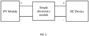
- the communication between a photovoltaic module, an electronics module, and an electrochromic glazing is depicted in FIG. 2 .
- FIG. 3 A flow chart showing the operational control or logic of an embodiment of an electronics module is depicted in FIG. 3 .
- the electronics module is capable of wireless communication with a central control system, building management system (BMS), or other user interface (collectively referred to herein as "control system”).
- BMS building management system
- control system the BMS interface could be BACnet, LonWorks, KNX, or any other such interface.
- the wireless communication can be used, for example, for manual over-ride selection of a specific state, synchronization between multiple panes, or integration with a building automation system, and optionally, energy storage (battery or super-capacitor) to permit rapid switching in low light, or switching in anticipation of an event (such as sunrise or sunset).
- the control system could link to the electrochromic systems described above via infrared pulses, radio waves, ultrasonic waves, or another wireless communication medium as described in United States Patent Nos. 7,277,215 , 7,133,181 , and 6,055,089 .
- wireless communications are through a standard protocol, for example a Zigbee mesh network, 802.11 WiFi, or Bluetooth.
- Proprietary solutions could also be used.
- Wireless communication protocols will typically be accomplished using integrated circuits or modules specifically designed for the purpose. Modules appropriate for the purpose include those manufactured by, for example, Digi International, Synapse Wireless, Motorola, or Panasonic.
- the antenna could be a separately mounted module, a component in the electronics module, or designed into the printed wiring board (PWB) itself.
- the antenna could be formed on the glass itself from transparent conductors or bus bar material.
- the photovoltaic module could have space to mount a flat antenna structure, such as where there are no photovoltaic cells.
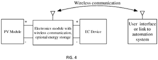
- FIG. 4 The communication and/or integration between a photovoltaic module, an electronics module, and an electrochromic device, all in wireless communication with a user interface or link to an automation system, is depicted in FIG. 4 .
- the electronics module in some embodiments, is also capable of communicating directly with other electronics modules in other electrochromic systems or other building systems (via wired or wireless communication). For example, if a Zigbee mesh is used, all units can talk directly to each other, permitting them to coordinate tint level for a uniform appearance.
- a module with a Bluetooth interface could directly communicate with wireless telephones.
- a module with a WiFi (802.11) interface could communicate directly with desktop or portable PCs or routers.
- the electrochromic systems further comprise a battery separate from the electronics module.
- the battery is rechargeable or user-replaceable, i.e., in routine maintenance, the battery (or batteries) may be replaced if their performance drops.
- Suitable batteries include those based on various lithium technologies, nickel-cadmium or nickel-metal-hydride. Lithium-ion cells with iron-phosphate cathodes (LiFePO4 cells) offer long life, good performance over temperature, and safety appropriate to this application. As alternative storage technologies evolve, they could become suitable suitable for use with the present invenion, including technologies such as supercapacitors/ultracapacitors or thin-film batteries.
- the photovoltaic module or electronics module could optionally comprise additional interfaces or modules for future expansion purposes. Any control system could likewise be used to control these additional interfaces or modules. For example, it is entirely possible to incorporate interfaces or modules for the future addition of lighting systems, e.g. LED lights, into each electrochromic system, or information displays to show status of the glazings or other information. Specific examples of different methods of incorporating an electrochromic glazing/IGU, a photovoltaic module, and an electronics module into an electrochromic system are described further in the following examples.
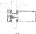
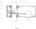
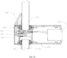
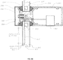
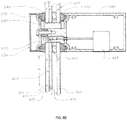
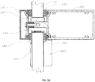
- Fig. 5A , 5B and 5D illustrate a combined photovoltaic/electronics module 100.
- the combined photovoltaic/electronics module 100 (with or without wireless communication) for an electrochromic glazing 110 is mounted to the exterior of the building or window framing system 130.
- the photovoltaic/electronics module (with wireless communication) is mounted on a portion of the frame which has available space within the frame for an electrical connection 120 and exterior access to the glazing pocket, as depicted in FIG. 5 .
- a glazing pocket as that term is understood in the art, is the unfilled space immediately surrounding the IGU to allow for installation and IGU size tolerance.
- a pressure-plate system is an example of such a system.
- the electrical connection 120 between IGU and control systems is made with a water-resistant electrical connector capable of supplying the voltage and current requirements of the IGU.
- Other elements shown in FIG. 5 include an exterior seal 140, clamp plate cover 150, frame clamp plate 160, interior seal 170, and interior frame 180.
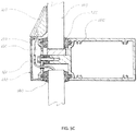
- Figure 5C shows one embodiment of the invention.
- the combined photovoltaic/electronics module can have any thickness.
- the combined PV/wireless control module is preferably less than about 10mm thick, more preferably less than about 6mm thick, so as to minimize its visual impact.
- the visible surface will be almost entirely comprised of a photovoltaic surface (cells).
- Fig. 6 illustrates an electronics module 205 inside or protruding into the building or window framing system.
- a photovoltaic module 200 is mounted on the exterior surface 230, with the electronics module 205 inside or protruding into the building or window framing system. It is believed that this would further minimize the profile of the resulting system.
- the electronics could hang freely.
- the electronics could be mounted to the frame cover.
- the electronics could be mounted to the pressure plate, as depicted in FIG. 6 .
- Other features include an exterior seal 240, clamp plate cover 250, frame clamp plate 260, exterior surface 230, electrochromic device or IGU 210, interior seal 270, and interior frame 280.
- the electronics module 305 is moved to the interior frame, as compared to the placement depicted in FIG. 6 . It is believed that this has the benefit of allowing replacement of either the electronics module or the replacement of an optional rechargeable battery, from the inside of the space.
- the electronics module and battery may be combined into a single unit or may be kept separate.
- the electronics module 465 in some embodiments, is located in the interior building frame. While it is believed that this may result in a partial loss of vision area, this design, it is believed, simplifies installation by eliminating a wiring connection. It is also believed that this particular configuration may reduce costs and improve reliability by eliminating the need to environmentally seal the photovoltaic unit. Based on about 15%-20% efficient crystalline cells comprising the photovoltaic module, it is estimated that about 2% to about 3% of glass area is required in systems with a battery, or up to 8% for systems without a battery, because of demands for high current when switching rapidly in moderate light levels. Other components shown include an IGU glazing lite 415, electrochromic layers 425, an IGU internal cavity 435, and an IGU spacer and seals 455.
- the photovoltaic module may, in some embodiments, share a common connection with the electrochromic glass.
- a 2-busbar electrochromic IGU with photovoltaic might only require three electrical penetrations. Further information on related positioning is described in United States Patent No. 6,055,089 .
- the feed-through between the glazing pocket and the interior of the building includes a flex circuit.
- any suitable penetration of the seal could be used, or any method of wireless energy transfer such as inductive or optical coupling.
- the connection may be provided through a sealed hole in the glass directly to the inside of the building or, in yet other embodiments, through conductors adhered directly to the glass surface.
- the IGU is installed in a glazing pocket while routing a pigtail wire from the IGU through an access hole in the building pressure plate.
- the exterior framing cover in then attached by standard means.
- a hole is then drilled in the cover large enough to reach in and make an electrical connection between the glazing and the control module.
- An electrical connection between wireless module and electrochromic glazing is made, and then mount module to surface of frame.
- the IGU is installed in a glazing pocket while routing a pigtail wire from the IGU through an access hole in the building pressure plate.
- the exterior framing cover is then attached by standard means.
- the IGU is installed in a glazing pocket while routing a pigtail wire from the IGU through an access hole in the building pressure plate.
- an electronics module and photovoltaic module are mounted to the framing system cover, with the photovoltaic on the outside and the electronics on the inside.
- the installer would then make a final connection between the cover-mounted electronics and the IGU pigtail.
- a cover plate is then attached in the usual manner.
- photovoltaic power generation is an objective
- the system would, it is believed, resemble a normal BIPV (building-integrated photovoltaic system) tightly integrated with an electrochromic glazing system.
- the excess power could, in some embodiments, be converted to grid power with an inverter, or connected directly to a low-voltage distribution system, such as that defined by the EMerge Alliance, for reduced installation cost and improved efficiency over a grid-tie system.
- the present invention can be applied to other types of electrically active glazings, such as those including LED lighting or automated blinds.
Landscapes
- Physics & Mathematics (AREA)
- Nonlinear Science (AREA)
- General Physics & Mathematics (AREA)
- Optics & Photonics (AREA)
- Electrochromic Elements, Electrophoresis, Or Variable Reflection Or Absorption Elements (AREA)
- Photovoltaic Devices (AREA)
- Liquid Crystal (AREA)
- Optical Communication System (AREA)
Claims (15)
- Vorrichtung zum Modulieren der Aussendung von Licht aus einer Lichtquelle, umfassend eine elektrochrome Verglasung (110, 210), die eine Lichtdurchlässigkeit aufweist, die als Reaktion auf einen elektrischen Strom veränderlich ist, wobei die elektrochrome Verglasung konfiguriert ist, um in einer Gebäudestruktur (130) installiert zu werden; mindestens ein Photovoltaikmodul (100, 200, 405), das elektrisch mit der elektrochromen Verglasung verbunden ist, um der elektrochromen Verglasung den elektrischen Strom als Reaktion auf das Licht bereitzustellen, das von der Lichtquelle auf das photovoltaische Modul auftrifft; und ein Elektronikmodul (100, 205, 305, 465) in Kommunikation mit entweder dem Photovoltaikmodul oder der elektrochromen Verglasung, wobei das Photovoltaikmodul an einer Außenoberfläche der elektrochromen Verglasung montiert ist, dadurch gekennzeichnet, dass eine Lichtempfangsoberfläche des an der Außenoberfläche der elektrochromen Verglasung montierten Photovoltaikmoduls in Bezug auf die Außenoberfläche in einem Winkel angeordnet ist, wobei das Photovoltaikmodul und das Elektronikmodul entweder zu einer einzigen Einheit (100) kombiniert oder an verschiedenen Orten montiert sind.
- Vorrichtung nach Anspruch 1, wobei das Elektronikmodul ein Drahtlos-Kommunikationsmodul umfasst, um eine Drahtlos-Kommunikation mit einem Gebäudeautomationssystem bereitzustellen.
- Vorrichtung nach Anspruch 1, wobei die elektrochrome Verglasung ein Laminat aus mindestens zwei Glasscheiben (416, 417, 418) ist.
- Vorrichtung nach Anspruch 1, wobei das Elektronikmodul an einer Innen- oder Außenoberfläche der elektrochromen Verglasung oder innerhalb der elektrochromen Verglasung montiert ist.
- Vorrichtung nach Anspruch 1, wobei das Elektronikmodul konfiguriert ist, um angrenzend an die elektrochrome Verglasung an einer inneren oder äußeren Gebäudestruktur (130) montiert zu werden.
- Vorrichtung nach Anspruch 1, wobei das Photovoltaikmodul und das Elektronikmodul an unterschiedlichen Orten montiert sind.
- Vorrichtung nach Anspruch 6, wobei sich das Photovoltaikmodul auf einer Außenoberfläche der elektrochromen Verglasung befindet und das Elektronikmodul konfiguriert ist, um sich innerhalb einer Gebäudestruktur (130) zu befinden oder in diese hineinragt, und wobei das Elektronikmodul ein Drahtlos-Kommunikationsmodul zur Drahtlos-Kommunikation mit einem Gebäudeautomationssystem umfasst.
- Vorrichtung nach Anspruch 6, wobei sich das Photovoltaikmodul auf einer Außenoberfläche der elektrochromen Verglasung befindet und das Elektronikmodul konfiguriert ist, um sich in einer inneren Gebäudestruktur zu befinden, und wobei das Elektronikmodul ein Drahtlos-Kommunikationsmodul zur Drahtlos-Kommunikation mit einem Gebäudeautomationssystem umfasst.
- Vorrichtung nach Anspruch 1, wobei das Photovoltaikmodul und das Elektronikmodul zu einer einzigen Einheit (100) kombiniert sind.
- Vorrichtung nach Anspruch 9, wobei das kombinierte Photovoltaik- und Elektronikmodul eine Dicke von weniger als etwa 10 mm aufweist.
- Vorrichtung nach Anspruch 1, wobei das Elektronikmodul auf die Sonnenintensität reagiert, sodass die elektrochrome Verglasung proportional zum verfügbaren Sonnenlicht getönt wird oder sich verfärbt.
- Vorrichtung nach Anspruch 1, wobei das Elektronikmodul Steuerungslogikmittel umfasst, wobei optional die Steuerungslogikmittel die aus dem Photovoltaikmodul verfügbare Energie überwachen.
- Vorrichtung nach Anspruch 1, ferner umfassend eine Batterie.
- Vorrichtung nach Anspruch 1, wobei das Photovoltaikmodul mit dem Elektronikmodul über eine elektrische Durchführung verbunden ist.
- Vorrichtung nach Anspruch 1, wobei das Photovoltaikmodul über Drahtlos-Energieübertragungsmittel mit dem Elektronikmodul gekoppelt ist.
Applications Claiming Priority (2)
| Application Number | Priority Date | Filing Date | Title |
|---|---|---|---|
| US201161435391P | 2011-01-24 | 2011-01-24 | |
| PCT/US2012/022033 WO2012102964A1 (en) | 2011-01-24 | 2012-01-20 | Control system for electrochromic device |
Publications (2)
| Publication Number | Publication Date |
|---|---|
| EP2668543A1 EP2668543A1 (de) | 2013-12-04 |
| EP2668543B1 true EP2668543B1 (de) | 2021-12-15 |
Family
ID=45607370
Family Applications (1)
| Application Number | Title | Priority Date | Filing Date |
|---|---|---|---|
| EP12704168.9A Active EP2668543B1 (de) | 2011-01-24 | 2012-01-20 | Steuerungssystem für eine elektrochrome vorrichtung |
Country Status (9)
| Country | Link |
|---|---|
| US (1) | US9250494B2 (de) |
| EP (1) | EP2668543B1 (de) |
| JP (1) | JP5858444B2 (de) |
| KR (1) | KR20140004175A (de) |
| CN (1) | CN103608719B (de) |
| AU (1) | AU2012209352B2 (de) |
| BR (1) | BR112013018421A2 (de) |
| RU (1) | RU2013137369A (de) |
| WO (1) | WO2012102964A1 (de) |
Families Citing this family (122)
| Publication number | Priority date | Publication date | Assignee | Title |
|---|---|---|---|---|
| US9782949B2 (en) | 2008-05-30 | 2017-10-10 | Corning Incorporated | Glass laminated articles and layered articles |
| US8514476B2 (en) | 2008-06-25 | 2013-08-20 | View, Inc. | Multi-pane dynamic window and method for making same |
| US10747082B2 (en) | 2009-12-22 | 2020-08-18 | View, Inc. | Onboard controller for multistate windows |
| US20130271813A1 (en) | 2012-04-17 | 2013-10-17 | View, Inc. | Controller for optically-switchable windows |
| US11732527B2 (en) | 2009-12-22 | 2023-08-22 | View, Inc. | Wirelessly powered and powering electrochromic windows |
| US10303035B2 (en) | 2009-12-22 | 2019-05-28 | View, Inc. | Self-contained EC IGU |
| US8213074B1 (en) | 2011-03-16 | 2012-07-03 | Soladigm, Inc. | Onboard controller for multistate windows |
| US20210063836A1 (en) | 2017-04-26 | 2021-03-04 | View, Inc. | Building network |
| EP3425450B1 (de) * | 2009-12-22 | 2021-11-24 | View, Inc. | Drahtlos angetriebene elektrochrome fenster |
| US11630366B2 (en) | 2009-12-22 | 2023-04-18 | View, Inc. | Window antennas for emitting radio frequency signals |
| US11592723B2 (en) | 2009-12-22 | 2023-02-28 | View, Inc. | Automated commissioning of controllers in a window network |
| US11342791B2 (en) | 2009-12-22 | 2022-05-24 | View, Inc. | Wirelessly powered and powering electrochromic windows |
| US11314139B2 (en) | 2009-12-22 | 2022-04-26 | View, Inc. | Self-contained EC IGU |
| US11205926B2 (en) | 2009-12-22 | 2021-12-21 | View, Inc. | Window antennas for emitting radio frequency signals |
| WO2016085964A1 (en) | 2014-11-25 | 2016-06-02 | View, Inc. | Window antennas |
| US10690540B2 (en) | 2015-10-06 | 2020-06-23 | View, Inc. | Multi-sensor having a light diffusing element around a periphery of a ring of photosensors |
| US9958750B2 (en) | 2010-11-08 | 2018-05-01 | View, Inc. | Electrochromic window fabrication methods |
| US9442339B2 (en) | 2010-12-08 | 2016-09-13 | View, Inc. | Spacers and connectors for insulated glass units |
| CN112731720A (zh) | 2010-12-08 | 2021-04-30 | 唯景公司 | 绝缘玻璃装置的改良隔板 |
| US10180606B2 (en) | 2010-12-08 | 2019-01-15 | View, Inc. | Connectors for smart windows |
| US8643933B2 (en) | 2011-12-14 | 2014-02-04 | View, Inc. | Connectors for smart windows |
| US10429712B2 (en) | 2012-04-20 | 2019-10-01 | View, Inc. | Angled bus bar |
| US9030725B2 (en) | 2012-04-17 | 2015-05-12 | View, Inc. | Driving thin film switchable optical devices |
| US9412290B2 (en) | 2013-06-28 | 2016-08-09 | View, Inc. | Controlling transitions in optically switchable devices |
| US8254013B2 (en) | 2011-03-16 | 2012-08-28 | Soladigm, Inc. | Controlling transitions in optically switchable devices |
| US10989977B2 (en) | 2011-03-16 | 2021-04-27 | View, Inc. | Onboard controller for multistate windows |
| US9645465B2 (en) | 2011-03-16 | 2017-05-09 | View, Inc. | Controlling transitions in optically switchable devices |
| US10175549B2 (en) | 2011-03-16 | 2019-01-08 | View, Inc. | Connectors for smart windows |
| US10935865B2 (en) | 2011-03-16 | 2021-03-02 | View, Inc. | Driving thin film switchable optical devices |
| US11822202B2 (en) | 2011-03-16 | 2023-11-21 | View, Inc. | Controlling transitions in optically switchable devices |
| US8705162B2 (en) | 2012-04-17 | 2014-04-22 | View, Inc. | Controlling transitions in optically switchable devices |
| US11054792B2 (en) | 2012-04-13 | 2021-07-06 | View, Inc. | Monitoring sites containing switchable optical devices and controllers |
| US9778532B2 (en) | 2011-03-16 | 2017-10-03 | View, Inc. | Controlling transitions in optically switchable devices |
| US11630367B2 (en) | 2011-03-16 | 2023-04-18 | View, Inc. | Driving thin film switchable optical devices |
| US9454055B2 (en) | 2011-03-16 | 2016-09-27 | View, Inc. | Multipurpose controller for multistate windows |
| CN103987909B (zh) | 2011-10-21 | 2017-03-22 | 唯景公司 | 减轻可着色窗中的热冲击 |
| US11719039B2 (en) | 2011-12-14 | 2023-08-08 | View, Inc. | Connectors for smart windows |
| US9281672B2 (en) | 2012-01-20 | 2016-03-08 | Sage Electrochromics, Inc. | Electrical connectivity within architectural glazing frame systems |
| US20130222877A1 (en) | 2012-02-28 | 2013-08-29 | Sage Electrochromics, Inc. | Multi-zone electrochromic devices |
| US12153320B2 (en) | 2012-03-13 | 2024-11-26 | View, Inc. | Multi-zone EC windows |
| US11635666B2 (en) * | 2012-03-13 | 2023-04-25 | View, Inc | Methods of controlling multi-zone tintable windows |
| US9341912B2 (en) | 2012-03-13 | 2016-05-17 | View, Inc. | Multi-zone EC windows |
| US12578609B2 (en) | 2012-03-13 | 2026-03-17 | View Operating Corporation | Methods of controlling multi-zone tintable windows |
| US11950340B2 (en) | 2012-03-13 | 2024-04-02 | View, Inc. | Adjusting interior lighting based on dynamic glass tinting |
| US9638978B2 (en) | 2013-02-21 | 2017-05-02 | View, Inc. | Control method for tintable windows |
| US12400651B2 (en) | 2012-04-13 | 2025-08-26 | View Operating Corporation | Controlling optically-switchable devices |
| US10503039B2 (en) | 2013-06-28 | 2019-12-10 | View, Inc. | Controlling transitions in optically switchable devices |
| US10048561B2 (en) | 2013-02-21 | 2018-08-14 | View, Inc. | Control method for tintable windows |
| US11674843B2 (en) | 2015-10-06 | 2023-06-13 | View, Inc. | Infrared cloud detector systems and methods |
| US10964320B2 (en) | 2012-04-13 | 2021-03-30 | View, Inc. | Controlling optically-switchable devices |
| US11300848B2 (en) | 2015-10-06 | 2022-04-12 | View, Inc. | Controllers for optically-switchable devices |
| US12619118B2 (en) | 2012-04-13 | 2026-05-05 | View Operating Corporation | Controlling transitions in optically switchable devices |
| EP3223532B1 (de) | 2012-04-13 | 2019-10-09 | View, Inc. | Anwendungen zur steuerung optisch schaltbarer vorrichtungen |
| US11255120B2 (en) | 2012-05-25 | 2022-02-22 | View, Inc. | Tester and electrical connectors for insulated glass units |
| WO2014032023A1 (en) | 2012-08-23 | 2014-02-27 | View, Inc. | Photonic-powered ec devices |
| US9618820B2 (en) | 2012-11-14 | 2017-04-11 | Solarwindow Technologies, Inc. | Integrated photovoltaic and electrochromic windows |
| US12372846B2 (en) | 2013-02-21 | 2025-07-29 | View Operating Corporation | Control methods and systems using external 3D modeling and schedule-based computing |
| US11966142B2 (en) | 2013-02-21 | 2024-04-23 | View, Inc. | Control methods and systems using outside temperature as a driver for changing window tint states |
| US12422725B2 (en) | 2013-02-21 | 2025-09-23 | View Operating Corporation | Control methods and systems using outside temperature as a driver for changing window tint states |
| US11960190B2 (en) | 2013-02-21 | 2024-04-16 | View, Inc. | Control methods and systems using external 3D modeling and schedule-based computing |
| US11719990B2 (en) | 2013-02-21 | 2023-08-08 | View, Inc. | Control method for tintable windows |
| WO2014134451A2 (en) * | 2013-03-01 | 2014-09-04 | New Energy Technologies, Inc. | Building intergrated photovoltaic devices as smart sensors for intelligent building energy management systems |
| CN105324708B (zh) | 2013-06-18 | 2020-02-14 | 唯景公司 | 非矩形形状上的电致变色设备 |
| US12061404B2 (en) | 2013-06-28 | 2024-08-13 | View, Inc. | Controlling transitions in optically switchable devices |
| US9885935B2 (en) | 2013-06-28 | 2018-02-06 | View, Inc. | Controlling transitions in optically switchable devices |
| US12353111B2 (en) | 2013-06-28 | 2025-07-08 | View Operating Corporation | Controlling transitions in optically switchable devices |
| ES2727517T3 (es) * | 2013-08-19 | 2019-10-16 | Tropiglas Tech Ltd | Un dispositivo para generar energía eléctrica |
| US10221612B2 (en) | 2014-02-04 | 2019-03-05 | View, Inc. | Infill electrochromic windows |
| US11868103B2 (en) | 2014-03-05 | 2024-01-09 | View, Inc. | Site monitoring system |
| US11150616B2 (en) | 2014-03-05 | 2021-10-19 | View, Inc. | Site monitoring system |
| KR102336168B1 (ko) | 2014-03-05 | 2021-12-07 | 뷰, 인크. | 스위칭가능한 광 디바이스들 및 제어기들을 포함하는 사이트들 모니터링 |
| JP6526068B2 (ja) * | 2014-06-25 | 2019-06-05 | セイジ・エレクトロクロミクス,インコーポレイテッド | スケーラブルなサイズ及び電力容量を有する太陽光発電装置 |
| WO2015200091A1 (en) * | 2014-06-25 | 2015-12-30 | Sage Electrochromics, Inc. | Method of pre-attaching assemblies to an electrochromic glazing for accurate fit or registration after installation |
| US10481459B2 (en) | 2014-06-30 | 2019-11-19 | View, Inc. | Control methods and systems for networks of optically switchable windows during reduced power availability |
| US10365532B2 (en) | 2015-09-18 | 2019-07-30 | View, Inc. | Power distribution networks for electrochromic devices |
| US10859887B2 (en) | 2015-09-18 | 2020-12-08 | View, Inc. | Power distribution networks for electrochromic devices |
| US11003041B2 (en) | 2014-06-30 | 2021-05-11 | View, Inc. | Power management for electrochromic window networks |
| WO2018039080A1 (en) | 2016-08-22 | 2018-03-01 | View, Inc. | Electromagnetic-shielding electrochromic windows |
| US11114742B2 (en) * | 2014-11-25 | 2021-09-07 | View, Inc. | Window antennas |
| US12235560B2 (en) | 2014-11-25 | 2025-02-25 | View, Inc. | Faster switching electrochromic devices |
| CA2970300A1 (en) | 2014-12-08 | 2016-06-16 | View, Inc. | Multiple interacting systems at a site |
| US11740948B2 (en) | 2014-12-08 | 2023-08-29 | View, Inc. | Multiple interacting systems at a site |
| US10975612B2 (en) | 2014-12-15 | 2021-04-13 | View, Inc. | Seals for electrochromic windows |
| US10520783B2 (en) | 2014-12-19 | 2019-12-31 | View, Inc. | Mitigating defects in an electrochromic device under a bus bar |
| EP3242989A4 (de) | 2015-01-06 | 2018-12-12 | Sage Electrochromics, Inc. | Satz aus fensteranordnungen und verfahren zur herstellung davon |
| US9906187B2 (en) | 2015-01-06 | 2018-02-27 | Sage Electrochromics, Inc. | Window assembly and a method regarding the same |
| US10508487B2 (en) * | 2015-06-17 | 2019-12-17 | Sharp Kabushiki Kaisha | Dimming system |
| TWI746446B (zh) | 2015-07-07 | 2021-11-21 | 美商唯景公司 | 用於可著色窗戶之控制方法 |
| KR102685304B1 (ko) | 2015-09-18 | 2024-07-16 | 뷰, 인크. | 전기변색 디바이스들을 위한 파워 분배 네트워크들 |
| US11384596B2 (en) | 2015-09-18 | 2022-07-12 | View, Inc. | Trunk line window controllers |
| US12366111B2 (en) | 2015-09-18 | 2025-07-22 | View Operating Corporation | Trunk line window controllers |
| US11255722B2 (en) | 2015-10-06 | 2022-02-22 | View, Inc. | Infrared cloud detector systems and methods |
| AU2016346328B2 (en) | 2015-10-29 | 2022-04-28 | View, Inc. | Controllers for optically-switchable devices |
| CN105421256B (zh) * | 2015-12-28 | 2018-05-22 | 招商局重庆交通科研设计院有限公司 | 公路隧道洞口绿色节能防眩系统 |
| EP4130865B1 (de) | 2016-04-29 | 2025-10-22 | View, Inc. | Kalibrierung von elektrischen parametern bei optisch schaltbaren fenstern |
| US11623433B2 (en) | 2016-06-17 | 2023-04-11 | View, Inc. | Mitigating defects in an electrochromic device under a bus bar |
| CN106088995B (zh) * | 2016-08-23 | 2018-01-16 | 北京艾科斯玛特自动化控制技术有限公司 | 自动检测门窗故障的方法和机构 |
| KR20190040056A (ko) | 2016-08-24 | 2019-04-16 | 키네스트랄 테크놀로지스, 인크. | 전기 변색 디바이스에 대한 부스트 회로 |
| CN108086872A (zh) * | 2016-11-23 | 2018-05-29 | 合肥威迪变色玻璃有限公司 | 电致变色的夹层玻璃、窗户及幕墙显示系统 |
| JP6793855B2 (ja) | 2016-12-22 | 2020-12-02 | セイジ・エレクトロクロミクス,インコーポレイテッド | 連続勾配透過状態を維持するように構成されたエレクトロクロミックデバイスを含む装置 |
| US11320713B2 (en) | 2017-02-16 | 2022-05-03 | View, Inc. | Solar power dynamic glass for heating and cooling buildings |
| CA3124139C (en) | 2017-04-12 | 2023-09-12 | Inovues, Inc | System and method for retrofitting glazing systems of buildings |
| TW201907213A (zh) * | 2017-04-26 | 2019-02-16 | 美商唯景公司 | 可著色窗系統計算平台 |
| US11747696B2 (en) | 2017-04-26 | 2023-09-05 | View, Inc. | Tandem vision window and media display |
| US11892738B2 (en) | 2017-04-26 | 2024-02-06 | View, Inc. | Tandem vision window and media display |
| US11513412B2 (en) | 2017-04-26 | 2022-11-29 | View, Inc. | Displays for tintable windows |
| US12147142B2 (en) | 2017-04-26 | 2024-11-19 | View, Inc. | Remote management of a facility |
| US11747698B2 (en) | 2017-04-26 | 2023-09-05 | View, Inc. | Tandem vision window and media display |
| US12339557B2 (en) | 2017-04-26 | 2025-06-24 | View, Inc. | Configuration associated with media display of a facility |
| US12603091B2 (en) | 2017-04-26 | 2026-04-14 | View Operating Corporation | Immersive collaboration of remote participants via media displays |
| CN107419829A (zh) * | 2017-06-12 | 2017-12-01 | 苏州寅初信息科技有限公司 | 一种自动调节透光率的建筑幕墙系统 |
| CN107165542A (zh) * | 2017-07-19 | 2017-09-15 | 南京盈润建筑工程配套有限公司 | 一种智能遮阳集成系统窗及其控制系统 |
| US20220282567A1 (en) * | 2019-01-16 | 2022-09-08 | Timothy Koch | Window system and method utilizing a window pane assembly and locking system for easy insertion of a window pane assembly with electronically controllable scalable apertures for attenuating or otherwise modulating light transmission through said assembly |
| MX2021012990A (es) * | 2019-04-22 | 2022-04-06 | Solarwindow Tech Inc | Dispositivo de transferencia y dispositivo de recepción de barra espaciadora eléctrica. |
| JP7644501B2 (ja) | 2019-05-09 | 2025-03-12 | ビュー オペレーティング コーポレーション | 建物内の制御されたカバレッジのためのアンテナシステム |
| US11631493B2 (en) | 2020-05-27 | 2023-04-18 | View Operating Corporation | Systems and methods for managing building wellness |
| EP3977557A1 (de) | 2019-05-31 | 2022-04-06 | View, Inc. | Gebäudeantenne |
| TW202206925A (zh) | 2020-03-26 | 2022-02-16 | 美商視野公司 | 多用戶端網路中之存取及傳訊 |
| DE202020102785U1 (de) | 2020-05-15 | 2020-06-16 | Benjamin Meyer | Beleuchtetes Fassadensystem |
| EP4399567A4 (de) * | 2021-09-07 | 2025-07-30 | Sage Electrochromics Inc | Isolierverglasungseinheit mit integriertem elektronikmodul |
| US20240103331A1 (en) * | 2022-09-23 | 2024-03-28 | Sage Electrochromics, Inc. | Flexible controls for smart glass |
| CN116482908A (zh) * | 2023-04-21 | 2023-07-25 | 浙江景昇薄膜科技有限公司 | 一种电致变色装置及其安装方法 |
Citations (3)
| Publication number | Priority date | Publication date | Assignee | Title |
|---|---|---|---|---|
| JPS58131021U (ja) * | 1982-02-26 | 1983-09-05 | 旭硝子株式会社 | 調光装置 |
| JPS59191017A (ja) * | 1983-04-14 | 1984-10-30 | Tokyo Tatsuno Co Ltd | 窓ガラス |
| US5040585A (en) * | 1988-02-12 | 1991-08-20 | Yoshida Kogyo K. K. | Solar cell panel assembly for driving a motor-driven screen apparatus |
Family Cites Families (16)
| Publication number | Priority date | Publication date | Assignee | Title |
|---|---|---|---|---|
| JPS60253688A (ja) * | 1984-05-29 | 1985-12-14 | シャープ株式会社 | 日射制御装置窓 |
| IT1249602B (it) * | 1991-02-21 | 1995-03-09 | Consiglio Nazionale Ricerche | Serramento ventilato per la climatizzazione di edifici |
| JPH05147983A (ja) | 1991-11-25 | 1993-06-15 | Nippondenso Co Ltd | 光透過率可変ガラス |
| US20080297265A1 (en) * | 2006-08-05 | 2008-12-04 | Min Ming Tarng | 4Less-TSOC of XLC, QBXOCK, QBTCXO, QBVCXO, SMLDVR and ANLVCO or 4Free-TSOC of XLC, QBXOCK, QBTCXO, QBVCXO, SMLDVR and ANLKVCO |
| US9520827B2 (en) * | 2006-08-05 | 2016-12-13 | Anlinx | Zilinx : the 11 less green technology for FPIC of smart window |
| US7511589B2 (en) * | 2006-08-05 | 2009-03-31 | Tang System | DFY of XtalClkChip: design for yield of trimming-free crystal-free precision reference clock osillator IC chip |
| FR2728696A1 (fr) | 1994-12-23 | 1996-06-28 | Saint Gobain Vitrage | Procede d'alimentation electrique d'un vitrage electrocommandable |
| US6130772A (en) * | 1997-06-06 | 2000-10-10 | Cava; Frank James | Electrochromic device and method |
| US6055089A (en) * | 1999-02-25 | 2000-04-25 | Minnesota Mining And Manufacturing Company | Photovoltaic powering and control system for electrochromic windows |
| US6407847B1 (en) * | 2000-07-25 | 2002-06-18 | Gentex Corporation | Electrochromic medium having a color stability |
| JP2005282106A (ja) * | 2004-03-29 | 2005-10-13 | Kyocera Corp | 調光ガラス窓システム |
| JP2008059859A (ja) * | 2006-08-30 | 2008-03-13 | Toshiba Corp | 調光装置 |
| US20080234893A1 (en) | 2007-03-23 | 2008-09-25 | The Boeing Company | Window control system |
| KR20110021934A (ko) * | 2008-05-30 | 2011-03-04 | 코닝 인코포레이티드 | 광기전성 유리 적층 물품 및 층 물품 |
| JP2011002733A (ja) | 2009-06-22 | 2011-01-06 | Central Motor Co Ltd | 窓ガラス調光システム |
| WO2012079159A1 (en) * | 2010-12-15 | 2012-06-21 | Switch Materials Inc. | Variable transmittance optical devices |
-
2012
- 2012-01-20 EP EP12704168.9A patent/EP2668543B1/de active Active
- 2012-01-20 US US13/354,863 patent/US9250494B2/en not_active Expired - Fee Related
- 2012-01-20 AU AU2012209352A patent/AU2012209352B2/en not_active Expired - Fee Related
- 2012-01-20 BR BR112013018421A patent/BR112013018421A2/pt not_active Application Discontinuation
- 2012-01-20 KR KR1020137021499A patent/KR20140004175A/ko not_active Withdrawn
- 2012-01-20 RU RU2013137369/28A patent/RU2013137369A/ru not_active Application Discontinuation
- 2012-01-20 CN CN201280010523.3A patent/CN103608719B/zh not_active Expired - Fee Related
- 2012-01-20 WO PCT/US2012/022033 patent/WO2012102964A1/en not_active Ceased
- 2012-01-20 JP JP2013550618A patent/JP5858444B2/ja not_active Expired - Fee Related
Patent Citations (3)
| Publication number | Priority date | Publication date | Assignee | Title |
|---|---|---|---|---|
| JPS58131021U (ja) * | 1982-02-26 | 1983-09-05 | 旭硝子株式会社 | 調光装置 |
| JPS59191017A (ja) * | 1983-04-14 | 1984-10-30 | Tokyo Tatsuno Co Ltd | 窓ガラス |
| US5040585A (en) * | 1988-02-12 | 1991-08-20 | Yoshida Kogyo K. K. | Solar cell panel assembly for driving a motor-driven screen apparatus |
Also Published As
| Publication number | Publication date |
|---|---|
| US9250494B2 (en) | 2016-02-02 |
| RU2013137369A (ru) | 2015-03-10 |
| WO2012102964A1 (en) | 2012-08-02 |
| US20120194895A1 (en) | 2012-08-02 |
| AU2012209352B2 (en) | 2015-05-14 |
| JP2014505905A (ja) | 2014-03-06 |
| BR112013018421A2 (pt) | 2016-10-11 |
| EP2668543A1 (de) | 2013-12-04 |
| CN103608719B (zh) | 2018-02-23 |
| AU2012209352A1 (en) | 2013-08-22 |
| JP5858444B2 (ja) | 2016-02-10 |
| CN103608719A (zh) | 2014-02-26 |
| KR20140004175A (ko) | 2014-01-10 |
Similar Documents
| Publication | Publication Date | Title |
|---|---|---|
| US9250494B2 (en) | Control system for electrochromic device | |
| EP3161956B1 (de) | Solarbetriebene vorrichtung mit skalierbarer grösse und leistung | |
| KR102862536B1 (ko) | 광학적으로 전환가능한 소자를 위한 제어기 | |
| US20190296684A1 (en) | Photovoltaic facade element | |
| KR20110083248A (ko) | 태양광 블라인드 창호 | |
| WO2018132491A1 (en) | Window-integrated transparent photovoltaic module | |
| CN104321497A (zh) | 控制光可切换器件的转换 | |
| US20190249487A1 (en) | Building facade or roof | |
| CN117881870A (zh) | 用于光学可切换设备的控制器 | |
| US11513337B2 (en) | Electrical connections for supplying power to insulating glass unit interiors, and/or associated methods | |
| CN121312292A (zh) | 功能性玻璃和人造玻璃层压件 | |
| CN114771219A (zh) | 一种基于太阳能电池膜的车机控制天幕系统及其控制方法 | |
| KR101970778B1 (ko) | 태양광 발전 블라인드 | |
| JP2025141592A (ja) | 太陽電池ガラス | |
| CN220433992U (zh) | 一种可遮挡阳光的玻璃幕墙 | |
| CN222376315U (zh) | 一种智能调光bipv玻璃、控制系统及建筑 | |
| CN121900083A (zh) | 一种光伏变色玻璃组件及其制备方法 |
Legal Events
| Date | Code | Title | Description |
|---|---|---|---|
| PUAI | Public reference made under article 153(3) epc to a published international application that has entered the european phase |
Free format text: ORIGINAL CODE: 0009012 |
|
| 17P | Request for examination filed |
Effective date: 20130725 |
|
| AK | Designated contracting states |
Kind code of ref document: A1 Designated state(s): AL AT BE BG CH CY CZ DE DK EE ES FI FR GB GR HR HU IE IS IT LI LT LU LV MC MK MT NL NO PL PT RO RS SE SI SK SM TR |
|
| DAX | Request for extension of the european patent (deleted) | ||
| 17Q | First examination report despatched |
Effective date: 20150723 |
|
| STAA | Information on the status of an ep patent application or granted ep patent |
Free format text: STATUS: EXAMINATION IS IN PROGRESS |
|
| GRAP | Despatch of communication of intention to grant a patent |
Free format text: ORIGINAL CODE: EPIDOSNIGR1 |
|
| STAA | Information on the status of an ep patent application or granted ep patent |
Free format text: STATUS: GRANT OF PATENT IS INTENDED |
|
| INTG | Intention to grant announced |
Effective date: 20200803 |
|
| GRAJ | Information related to disapproval of communication of intention to grant by the applicant or resumption of examination proceedings by the epo deleted |
Free format text: ORIGINAL CODE: EPIDOSDIGR1 |
|
| STAA | Information on the status of an ep patent application or granted ep patent |
Free format text: STATUS: EXAMINATION IS IN PROGRESS |
|
| INTC | Intention to grant announced (deleted) | ||
| GRAP | Despatch of communication of intention to grant a patent |
Free format text: ORIGINAL CODE: EPIDOSNIGR1 |
|
| STAA | Information on the status of an ep patent application or granted ep patent |
Free format text: STATUS: GRANT OF PATENT IS INTENDED |
|
| INTG | Intention to grant announced |
Effective date: 20210218 |
|
| GRAJ | Information related to disapproval of communication of intention to grant by the applicant or resumption of examination proceedings by the epo deleted |
Free format text: ORIGINAL CODE: EPIDOSDIGR1 |
|
| STAA | Information on the status of an ep patent application or granted ep patent |
Free format text: STATUS: EXAMINATION IS IN PROGRESS |
|
| INTC | Intention to grant announced (deleted) | ||
| GRAP | Despatch of communication of intention to grant a patent |
Free format text: ORIGINAL CODE: EPIDOSNIGR1 |
|
| STAA | Information on the status of an ep patent application or granted ep patent |
Free format text: STATUS: GRANT OF PATENT IS INTENDED |
|
| INTG | Intention to grant announced |
Effective date: 20210730 |
|
| GRAS | Grant fee paid |
Free format text: ORIGINAL CODE: EPIDOSNIGR3 |
|
| GRAA | (expected) grant |
Free format text: ORIGINAL CODE: 0009210 |
|
| STAA | Information on the status of an ep patent application or granted ep patent |
Free format text: STATUS: THE PATENT HAS BEEN GRANTED |
|
| AK | Designated contracting states |
Kind code of ref document: B1 Designated state(s): AL AT BE BG CH CY CZ DE DK EE ES FI FR GB GR HR HU IE IS IT LI LT LU LV MC MK MT NL NO PL PT RO RS SE SI SK SM TR |
|
| REG | Reference to a national code |
Ref country code: GB Ref legal event code: FG4D Ref country code: CH Ref legal event code: EP |
|
| REG | Reference to a national code |
Ref country code: IE Ref legal event code: FG4D Ref country code: DE Ref legal event code: R096 Ref document number: 602012077358 Country of ref document: DE |
|
| REG | Reference to a national code |
Ref country code: AT Ref legal event code: REF Ref document number: 1455936 Country of ref document: AT Kind code of ref document: T Effective date: 20220115 |
|
| REG | Reference to a national code |
Ref country code: NL Ref legal event code: FP |
|
| REG | Reference to a national code |
Ref country code: LT Ref legal event code: MG9D |
|
| PG25 | Lapsed in a contracting state [announced via postgrant information from national office to epo] |
Ref country code: RS Free format text: LAPSE BECAUSE OF FAILURE TO SUBMIT A TRANSLATION OF THE DESCRIPTION OR TO PAY THE FEE WITHIN THE PRESCRIBED TIME-LIMIT Effective date: 20211215 Ref country code: LT Free format text: LAPSE BECAUSE OF FAILURE TO SUBMIT A TRANSLATION OF THE DESCRIPTION OR TO PAY THE FEE WITHIN THE PRESCRIBED TIME-LIMIT Effective date: 20211215 Ref country code: FI Free format text: LAPSE BECAUSE OF FAILURE TO SUBMIT A TRANSLATION OF THE DESCRIPTION OR TO PAY THE FEE WITHIN THE PRESCRIBED TIME-LIMIT Effective date: 20211215 Ref country code: BG Free format text: LAPSE BECAUSE OF FAILURE TO SUBMIT A TRANSLATION OF THE DESCRIPTION OR TO PAY THE FEE WITHIN THE PRESCRIBED TIME-LIMIT Effective date: 20220315 |
|
| REG | Reference to a national code |
Ref country code: AT Ref legal event code: MK05 Ref document number: 1455936 Country of ref document: AT Kind code of ref document: T Effective date: 20211215 |
|
| PG25 | Lapsed in a contracting state [announced via postgrant information from national office to epo] |
Ref country code: SE Free format text: LAPSE BECAUSE OF FAILURE TO SUBMIT A TRANSLATION OF THE DESCRIPTION OR TO PAY THE FEE WITHIN THE PRESCRIBED TIME-LIMIT Effective date: 20211215 Ref country code: NO Free format text: LAPSE BECAUSE OF FAILURE TO SUBMIT A TRANSLATION OF THE DESCRIPTION OR TO PAY THE FEE WITHIN THE PRESCRIBED TIME-LIMIT Effective date: 20220315 Ref country code: LV Free format text: LAPSE BECAUSE OF FAILURE TO SUBMIT A TRANSLATION OF THE DESCRIPTION OR TO PAY THE FEE WITHIN THE PRESCRIBED TIME-LIMIT Effective date: 20211215 Ref country code: HR Free format text: LAPSE BECAUSE OF FAILURE TO SUBMIT A TRANSLATION OF THE DESCRIPTION OR TO PAY THE FEE WITHIN THE PRESCRIBED TIME-LIMIT Effective date: 20211215 Ref country code: GR Free format text: LAPSE BECAUSE OF FAILURE TO SUBMIT A TRANSLATION OF THE DESCRIPTION OR TO PAY THE FEE WITHIN THE PRESCRIBED TIME-LIMIT Effective date: 20220316 |
|
| PG25 | Lapsed in a contracting state [announced via postgrant information from national office to epo] |
Ref country code: SM Free format text: LAPSE BECAUSE OF FAILURE TO SUBMIT A TRANSLATION OF THE DESCRIPTION OR TO PAY THE FEE WITHIN THE PRESCRIBED TIME-LIMIT Effective date: 20211215 Ref country code: SK Free format text: LAPSE BECAUSE OF FAILURE TO SUBMIT A TRANSLATION OF THE DESCRIPTION OR TO PAY THE FEE WITHIN THE PRESCRIBED TIME-LIMIT Effective date: 20211215 Ref country code: RO Free format text: LAPSE BECAUSE OF FAILURE TO SUBMIT A TRANSLATION OF THE DESCRIPTION OR TO PAY THE FEE WITHIN THE PRESCRIBED TIME-LIMIT Effective date: 20211215 Ref country code: PT Free format text: LAPSE BECAUSE OF FAILURE TO SUBMIT A TRANSLATION OF THE DESCRIPTION OR TO PAY THE FEE WITHIN THE PRESCRIBED TIME-LIMIT Effective date: 20220418 Ref country code: ES Free format text: LAPSE BECAUSE OF FAILURE TO SUBMIT A TRANSLATION OF THE DESCRIPTION OR TO PAY THE FEE WITHIN THE PRESCRIBED TIME-LIMIT Effective date: 20211215 Ref country code: EE Free format text: LAPSE BECAUSE OF FAILURE TO SUBMIT A TRANSLATION OF THE DESCRIPTION OR TO PAY THE FEE WITHIN THE PRESCRIBED TIME-LIMIT Effective date: 20211215 Ref country code: CZ Free format text: LAPSE BECAUSE OF FAILURE TO SUBMIT A TRANSLATION OF THE DESCRIPTION OR TO PAY THE FEE WITHIN THE PRESCRIBED TIME-LIMIT Effective date: 20211215 |
|
| PG25 | Lapsed in a contracting state [announced via postgrant information from national office to epo] |
Ref country code: PL Free format text: LAPSE BECAUSE OF FAILURE TO SUBMIT A TRANSLATION OF THE DESCRIPTION OR TO PAY THE FEE WITHIN THE PRESCRIBED TIME-LIMIT Effective date: 20211215 Ref country code: AT Free format text: LAPSE BECAUSE OF FAILURE TO SUBMIT A TRANSLATION OF THE DESCRIPTION OR TO PAY THE FEE WITHIN THE PRESCRIBED TIME-LIMIT Effective date: 20211215 |
|
| REG | Reference to a national code |
Ref country code: DE Ref legal event code: R097 Ref document number: 602012077358 Country of ref document: DE |
|
| PG25 | Lapsed in a contracting state [announced via postgrant information from national office to epo] |
Ref country code: MC Free format text: LAPSE BECAUSE OF FAILURE TO SUBMIT A TRANSLATION OF THE DESCRIPTION OR TO PAY THE FEE WITHIN THE PRESCRIBED TIME-LIMIT Effective date: 20211215 Ref country code: IS Free format text: LAPSE BECAUSE OF FAILURE TO SUBMIT A TRANSLATION OF THE DESCRIPTION OR TO PAY THE FEE WITHIN THE PRESCRIBED TIME-LIMIT Effective date: 20220415 |
|
| PLBE | No opposition filed within time limit |
Free format text: ORIGINAL CODE: 0009261 |
|
| STAA | Information on the status of an ep patent application or granted ep patent |
Free format text: STATUS: NO OPPOSITION FILED WITHIN TIME LIMIT |
|
| PG25 | Lapsed in a contracting state [announced via postgrant information from national office to epo] |
Ref country code: LU Free format text: LAPSE BECAUSE OF NON-PAYMENT OF DUE FEES Effective date: 20220120 Ref country code: DK Free format text: LAPSE BECAUSE OF FAILURE TO SUBMIT A TRANSLATION OF THE DESCRIPTION OR TO PAY THE FEE WITHIN THE PRESCRIBED TIME-LIMIT Effective date: 20211215 Ref country code: AL Free format text: LAPSE BECAUSE OF FAILURE TO SUBMIT A TRANSLATION OF THE DESCRIPTION OR TO PAY THE FEE WITHIN THE PRESCRIBED TIME-LIMIT Effective date: 20211215 |
|
| 26N | No opposition filed |
Effective date: 20220916 |
|
| PG25 | Lapsed in a contracting state [announced via postgrant information from national office to epo] |
Ref country code: SI Free format text: LAPSE BECAUSE OF FAILURE TO SUBMIT A TRANSLATION OF THE DESCRIPTION OR TO PAY THE FEE WITHIN THE PRESCRIBED TIME-LIMIT Effective date: 20211215 |
|
| PG25 | Lapsed in a contracting state [announced via postgrant information from national office to epo] |
Ref country code: IE Free format text: LAPSE BECAUSE OF NON-PAYMENT OF DUE FEES Effective date: 20220120 |
|
| PGFP | Annual fee paid to national office [announced via postgrant information from national office to epo] |
Ref country code: NL Payment date: 20221220 Year of fee payment: 12 Ref country code: GB Payment date: 20221221 Year of fee payment: 12 Ref country code: FR Payment date: 20221220 Year of fee payment: 12 |
|
| PGFP | Annual fee paid to national office [announced via postgrant information from national office to epo] |
Ref country code: BE Payment date: 20221220 Year of fee payment: 12 |
|
| PGFP | Annual fee paid to national office [announced via postgrant information from national office to epo] |
Ref country code: CH Payment date: 20230201 Year of fee payment: 12 |
|
| PG25 | Lapsed in a contracting state [announced via postgrant information from national office to epo] |
Ref country code: IT Free format text: LAPSE BECAUSE OF FAILURE TO SUBMIT A TRANSLATION OF THE DESCRIPTION OR TO PAY THE FEE WITHIN THE PRESCRIBED TIME-LIMIT Effective date: 20211215 |
|
| PGFP | Annual fee paid to national office [announced via postgrant information from national office to epo] |
Ref country code: DE Payment date: 20221220 Year of fee payment: 12 |
|
| P01 | Opt-out of the competence of the unified patent court (upc) registered |
Effective date: 20230530 |
|
| REG | Reference to a national code |
Ref country code: DE Ref legal event code: R082 Ref document number: 602012077358 Country of ref document: DE Representative=s name: KRAUS & LEDERER PARTGMBB, DE |
|
| PG25 | Lapsed in a contracting state [announced via postgrant information from national office to epo] |
Ref country code: HU Free format text: LAPSE BECAUSE OF FAILURE TO SUBMIT A TRANSLATION OF THE DESCRIPTION OR TO PAY THE FEE WITHIN THE PRESCRIBED TIME-LIMIT; INVALID AB INITIO Effective date: 20120120 |
|
| PG25 | Lapsed in a contracting state [announced via postgrant information from national office to epo] |
Ref country code: MK Free format text: LAPSE BECAUSE OF FAILURE TO SUBMIT A TRANSLATION OF THE DESCRIPTION OR TO PAY THE FEE WITHIN THE PRESCRIBED TIME-LIMIT Effective date: 20211215 Ref country code: CY Free format text: LAPSE BECAUSE OF FAILURE TO SUBMIT A TRANSLATION OF THE DESCRIPTION OR TO PAY THE FEE WITHIN THE PRESCRIBED TIME-LIMIT Effective date: 20211215 |
|
| PG25 | Lapsed in a contracting state [announced via postgrant information from national office to epo] |
Ref country code: TR Free format text: LAPSE BECAUSE OF FAILURE TO SUBMIT A TRANSLATION OF THE DESCRIPTION OR TO PAY THE FEE WITHIN THE PRESCRIBED TIME-LIMIT Effective date: 20211215 |
|
| REG | Reference to a national code |
Ref country code: DE Ref legal event code: R119 Ref document number: 602012077358 Country of ref document: DE |
|
| REG | Reference to a national code |
Ref country code: CH Ref legal event code: PL |
|
| REG | Reference to a national code |
Ref country code: NL Ref legal event code: MM Effective date: 20240201 |
|
| GBPC | Gb: european patent ceased through non-payment of renewal fee |
Effective date: 20240120 |
|
| PG25 | Lapsed in a contracting state [announced via postgrant information from national office to epo] |
Ref country code: MT Free format text: LAPSE BECAUSE OF FAILURE TO SUBMIT A TRANSLATION OF THE DESCRIPTION OR TO PAY THE FEE WITHIN THE PRESCRIBED TIME-LIMIT Effective date: 20211215 |
|
| PG25 | Lapsed in a contracting state [announced via postgrant information from national office to epo] |
Ref country code: DE Free format text: LAPSE BECAUSE OF NON-PAYMENT OF DUE FEES Effective date: 20240801 |
|
| PG25 | Lapsed in a contracting state [announced via postgrant information from national office to epo] |
Ref country code: GB Free format text: LAPSE BECAUSE OF NON-PAYMENT OF DUE FEES Effective date: 20240120 |
|
| PG25 | Lapsed in a contracting state [announced via postgrant information from national office to epo] |
Ref country code: BE Free format text: LAPSE BECAUSE OF NON-PAYMENT OF DUE FEES Effective date: 20240131 |
|
| PG25 | Lapsed in a contracting state [announced via postgrant information from national office to epo] |
Ref country code: FR Free format text: LAPSE BECAUSE OF NON-PAYMENT OF DUE FEES Effective date: 20240131 |
|
| PG25 | Lapsed in a contracting state [announced via postgrant information from national office to epo] |
Ref country code: NL Free format text: LAPSE BECAUSE OF NON-PAYMENT OF DUE FEES Effective date: 20240201 |
|
| PG25 | Lapsed in a contracting state [announced via postgrant information from national office to epo] |
Ref country code: CH Free format text: LAPSE BECAUSE OF NON-PAYMENT OF DUE FEES Effective date: 20240131 |
|
| PG25 | Lapsed in a contracting state [announced via postgrant information from national office to epo] |
Ref country code: NL Free format text: LAPSE BECAUSE OF NON-PAYMENT OF DUE FEES Effective date: 20240201 Ref country code: GB Free format text: LAPSE BECAUSE OF NON-PAYMENT OF DUE FEES Effective date: 20240120 Ref country code: FR Free format text: LAPSE BECAUSE OF NON-PAYMENT OF DUE FEES Effective date: 20240131 Ref country code: DE Free format text: LAPSE BECAUSE OF NON-PAYMENT OF DUE FEES Effective date: 20240801 Ref country code: CH Free format text: LAPSE BECAUSE OF NON-PAYMENT OF DUE FEES Effective date: 20240131 Ref country code: BE Free format text: LAPSE BECAUSE OF NON-PAYMENT OF DUE FEES Effective date: 20240131 |
|
| REG | Reference to a national code |
Ref country code: BE Ref legal event code: MM Effective date: 20240131 |