EP2667620A2 - Système permettant de projeter des images en 3D et de détecter des gestes - Google Patents
Système permettant de projeter des images en 3D et de détecter des gestes Download PDFInfo
- Publication number
- EP2667620A2 EP2667620A2 EP13167595.1A EP13167595A EP2667620A2 EP 2667620 A2 EP2667620 A2 EP 2667620A2 EP 13167595 A EP13167595 A EP 13167595A EP 2667620 A2 EP2667620 A2 EP 2667620A2
- Authority
- EP
- European Patent Office
- Prior art keywords
- imaging device
- images
- viewing area
- scene
- distinct
- Prior art date
- Legal status (The legal status is an assumption and is not a legal conclusion. Google has not performed a legal analysis and makes no representation as to the accuracy of the status listed.)
- Withdrawn
Links
Images

Classifications
-
- G—PHYSICS
- G06—COMPUTING; CALCULATING OR COUNTING
- G06F—ELECTRIC DIGITAL DATA PROCESSING
- G06F3/00—Input arrangements for transferring data to be processed into a form capable of being handled by the computer; Output arrangements for transferring data from processing unit to output unit, e.g. interface arrangements
- G06F3/01—Input arrangements or combined input and output arrangements for interaction between user and computer
- G06F3/017—Gesture based interaction, e.g. based on a set of recognized hand gestures
-
- G—PHYSICS
- G06—COMPUTING; CALCULATING OR COUNTING
- G06F—ELECTRIC DIGITAL DATA PROCESSING
- G06F3/00—Input arrangements for transferring data to be processed into a form capable of being handled by the computer; Output arrangements for transferring data from processing unit to output unit, e.g. interface arrangements
- G06F3/002—Specific input/output arrangements not covered by G06F3/01 - G06F3/16
- G06F3/005—Input arrangements through a video camera
-
- H—ELECTRICITY
- H04—ELECTRIC COMMUNICATION TECHNIQUE
- H04N—PICTORIAL COMMUNICATION, e.g. TELEVISION
- H04N13/00—Stereoscopic video systems; Multi-view video systems; Details thereof
- H04N13/30—Image reproducers
- H04N13/388—Volumetric displays, i.e. systems where the image is built up from picture elements distributed through a volume
- H04N13/39—Volumetric displays, i.e. systems where the image is built up from picture elements distributed through a volume the picture elements emitting light at places where a pair of light beams intersect in a transparent material
Definitions
- This disclosure generally relates to a three dimensional (3D) imaging system configured to display an autostereoscopic image of a scene toward a viewing area, and detect gestures occurring in the viewing area.
- 3D three dimensional
- Three dimension (3D) displays using specialized glasses are known.
- a cost effective way to display 3D images without using specialized glasses in combination with gesture recognition is desired.
- the invention consists on a three-dimensional imaging system configured to display an autostereoscopic image of a scene toward a viewing area, and detects gestures occurring in the viewing area
- the system includes an imaging device, a holographic diffuser, and a mirror arrangement.
- the imaging device is configured to project a plurality of projected images in distinct directions toward a projection field. Each projected image is characterized as a distinct perspective view of the scene.
- the imaging device also configured to detect a plurality of received images from the distinct directions.
- the mirror arrangement is fixedly positioned in the projection field.
- the mirror arrangement is configured to reflect the plurality of projected images from the imaging device toward the holographic diffuser in a manner effective to display an autostereoscopic image of the scene in the holographic diffuser.
- the mirror arrangement is also configured to reflect a plurality of perspective images from the viewing area toward the imaging device such that each received image corresponds to a distinct perspective view of the viewing area.
- the imaging device also includes a projector to project the plurality of projected images in distinct toward a projection field, and a camera to detect the plurality of received images from the distinct directions.
- the imaging device further includes an electrowetting prism configured to direct projected images from the projector in the distinct directions and to direct received images from the directions to the camera.
- An infrared camera to detect the plurality of received images is also part of the imaging device.
- the three-dimensional imaging system includes an infrared light emitter configured to illuminate the viewing area with IR light.
- the three-dimensional imaging system also includes a controller configured to determine a gesture based on the received images and to control the perspective of the scene displayed based on the gesture.
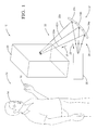
- Fig. 1 is a three dimensional (3D) imaging system in accordance with one embodiment
- Fig. 2 is a diagram of an imaging device in the system of Fig. 1 in accordance with an embodiment.
- Fig. 1 illustrates a non-limiting example of a three dimensional (3D) imaging system, hereafter the system 10.
- the system 10 is configured to display an autostereoscopic image of a scene toward a viewing area.
- a scene includes, but is not limited to, any object or location that could be photographed from different perspectives by a camera, or a synthesized or animated 3D model of the object or location.
- the viewing area 12 is a location proximate to the system 10 from where a person 14 may view the autostereoscopic image produced by the system 10. Further details regarding displaying autostereoscopic images are provided in United States Application for Patent Serial Number 13/282,555 by Kuhlman et al. , titled AUTOSTEROSCOPIC 3D DISPLAY, and filed October 27, 2011, the entire contents of which are hereby incorporated by reference herein.
- the system 10 is also generally configured to detect gestures occurring in the viewing area 12, for example gestures made by the person 14 moving a hand 16. As will become apparent in the description that follows, the gestures may include motions of the hand 16 in three dimensions, and so physical contact with the system 10 is not required.
- the system 10 may include an imaging device 20 configured to project a plurality of projected images indicated by lines showing distinct directions 22 that are individually indicated by lines 22a, 22b, 22c.
- the projected images travel toward a projection field 24 and travel in a projected direction 26.
- Each projected image may be characterized as a distinct perspective view of the scene that is to be displayed as part of an autostereoscopic image.
- the imaging device 20 may also be configured to detect a plurality of received images from the viewing area traveling along distinct directions 22 and traveling in a received direction 28.
- the system 10 may include a holographic diffuser 30.
- the display of an autostereoscopic image by the system 10 has been demonstrated using sheets of clear acrylic material treated on one side to have a translucent appearance that are available from Art-Friend, 391 Orchard Road, #04-20M, Ngee Ann City, Singapore 238872 ; Part numbers: AF463095 ACRYLIC SHT MATT CLEAR 3MM 9X12IN or AF4630951 ACRYLIC SHT MATT CLEAR 3MM 12X18IN.
- the holographic diffuser 30 may be similar to that described in United States Patent 4,799,739 to Newswanger , titled REAL TIME AUTOSTEREOSCOPIC DISPLAYS USING HOLOGRAPHIC DIFFUSERS, issued January 24, 1989; or United States Patent 5,609,939 to Peterson et al. , titled VIEWING SCREEN FORMED USING COHERENT LIGHT, issued March 11, 1997.
- the system 10 may include a mirror arrangement 32 fixedly positioned in the projection field 24.
- the mirror arrangement may include a plurality of flat mirrors 34a, 34b, 34c.
- the mirror arrangement 32 is generally configured to reflect the plurality of projected images projecting from the imaging device 20 and indicated by lines 22a, 22b, 22c as traveling in the projected direction 26 toward the holographic diffuser 30 in a manner effective to display an autostereoscopic image of the scene in the holographic diffuser 30.
- the mirror arrangement 32 is also generally configured to reflect a plurality of perspective images emanating from the viewing area 12 toward the imaging device 20 such that each received image corresponds to a distinct perspective view of the viewing area 12.
- the non-limiting examples provided herein suggest three projected images, e.g. the lines 22a, 22b, 22c. However it is appreciated that only two projected images are required to provide a 3D image to a person 14.
- the third projected image, or any number of additional projected images may be provided so the person 14 viewing the system 10 is not restricted to viewing from a single direction or a fixed viewing position, but may move to other viewing positions or viewing directions and still perceive a 3D image.
- the system 10 is able to show an autostereoscopic image that changes the apparent viewing perspective as the person 14 moves about the holographic diffuser 30.
- Each projected image may be characterized as a distinct perspective view of the scene or object being displayed.
- a projected image corresponding to line 22b may be characterized as a centered view of the scene being displayed;
- a projected image corresponding to line 22a may be characterized as a left-of-center view;
- a projected image corresponding to line 22c may be characterized as a right-of-center view. Which view enters which eye of the person 14 depends on the location of the person 14.
- the system 10 may be configured to project another row of projected images (not shown) aligned below the projected images indicated by lines 22a, 22b, 22c so that the person 14 could also move up and down and perceive a change in perspective just as the change in perspective is perceived by moving left and right.
- Fig. 2 illustrates a non-limiting example of the imaging device 20 that includes a projector 40 configured to project the plurality of projected images toward an optical device 42 that cooperates with the projector 40 to project the projected images in distinct directions 22 toward a projection field 24. It is recognized that multiple cameras could be used to accomplish the same task, but doing so may undesirably increase the cost of the imaging device 20.
- the projector 40 may be any commercially available projector, such as a pico-projector, that is selected based on a desired projection resolution and other performance characteristics.
- the optical device 42 may include a lens or combination of lenses that may variably control the focal distance and or viewing angle (e.g. narrow versus wide angle) of the optical device 42, the specifics of which is known to those skilled in the art of lenses.
- the optical device 42 may also include a Micro-Electro-Mechanical Systems (MEMS) actuated mirror that cooperates with the lens and the projector 40 to direct the projected images in distinct directions 22.
- MEMS Micro-Electro-Mechanical Systems
- the optical device 42 may use electrowetting technology to form an electrowetting prism and/or electrowetting lens to control the direction and focus of light passing through the optical device 42.
- the imaging device 20 may also include a camera 44 configured to detect the plurality of received images from the distinct directions 22.
- the camera 44 may be a visible light camera or an infrared camera. An infrared camera may be preferable in some instances where illumination is required to detect a gesture.
- the camera 44 may be any commercially available camera selected based on the desired resolution and other desired performance characteristics.
- the imaging device 20 may also include a beam splitter 46 arranged cooperatively with the projector 40 and the camera 44 so that the projected images and the received images can both pass through the optical device 42.
- the beam splitter 46 may be a half silvered mirror or a switchable mirror generally described as being operable to two states: transparent or reflective.
- Switchable mirrors include an LCD filled with crystals that are reflective in one state is available from Kentoptronics, or an electrowetting cell filled with liquid gallium, or an electrochromic mirror.
- the system 10 may include an infrared (IR) light emitter 48 configured to illuminate the viewing area with IR light 50.
- IR infrared
- the IR light emitter 48 is part of the imaging device 20. However it is recognized that the IR light emitter could be placed more proximate to the person 14 to effectively illuminate the hand 16.
- the system 10 may also include a controller 52 coupled to the various devices in the imaging device 20 in order to control those various devices.
- the controller may coordinate the operation of the projector 40, the optical device 42, the camera 44, the beam splitter 46, and the IR emitter 48.
- the controller 52 may be configured to determine a gesture based on the received images detected by the camera 44. Imaging processing algorithms for detecting gestures are generally known.
- the controller 52 may also be configured to control the perspective of the scene shown to the person by the holographic diffuser 30 displayed based on the gesture. For example, if the person 14 moves the hand 16 laterally, the controller may change the perspectives of the projected images so the scene displayed to the person 14 appears to rotate. Alternatively, the controller may be configured to output a control signal 54 to some other device or system in response to a gesture. For example, if the person 14 moves the hand 16 vertically, the controller 52 may output a control signal 54 to an audio entertainment system (not shown) effective to change the volume of music being output by the audio entertainment system.
- an audio entertainment system not shown
- the projected images indicated by lines 22a, 22b, 22c that are output by the imaging device 20 are generally narrow beams so that each projected image is seen by only one eye of the person 14.
- the size of the individual areas indicated by lines 22a, 22b, 22c that are seen by the camera 44 may be larger, and so the optical device 42 may preferably have a variable view angle.
- the area covered by the projected images may not correspond to the area covered by the received images, and this change in covered areas may be facilitated by the optical device 42 and or mirror arrangement 32.
- three dimensional (3D) imaging system (the system 10) configured to display an autostereoscopic image of a scene toward a viewing area, and detect gestures occurring in the viewing area is provided.
- the system makes dual use of some devices such as the mirror arrangement 32 and the optical device 42 so that both display of 3D images and detection of 3D gestures are available from an economical system.
Applications Claiming Priority (1)
| Application Number | Priority Date | Filing Date | Title |
|---|---|---|---|
| US13/477,737 US8823641B2 (en) | 2012-05-22 | 2012-05-22 | System for projecting 3D images and detecting gestures |
Publications (2)
| Publication Number | Publication Date |
|---|---|
| EP2667620A2 true EP2667620A2 (fr) | 2013-11-27 |
| EP2667620A3 EP2667620A3 (fr) | 2014-03-19 |
Family
ID=48577489
Family Applications (1)
| Application Number | Title | Priority Date | Filing Date |
|---|---|---|---|
| EP13167595.1A Withdrawn EP2667620A3 (fr) | 2012-05-22 | 2013-05-14 | Système permettant de projeter des images en 3D et de détecter des gestes |
Country Status (2)
| Country | Link |
|---|---|
| US (1) | US8823641B2 (fr) |
| EP (1) | EP2667620A3 (fr) |
Cited By (3)
| Publication number | Priority date | Publication date | Assignee | Title |
|---|---|---|---|---|
| WO2016057593A1 (fr) * | 2014-10-10 | 2016-04-14 | Microsoft Technology Licensing, Llc | Expérience de téléprésence |
| CN112180707A (zh) * | 2020-09-28 | 2021-01-05 | 四川大学 | 基于球面自衍射模型的球面纯相位全息图生成方法 |
| US11693364B2 (en) | 2017-11-30 | 2023-07-04 | Samsung Electronics Co., Ltd. | Holographic display and holographic image forming method |
Families Citing this family (8)
| Publication number | Priority date | Publication date | Assignee | Title |
|---|---|---|---|---|
| US9042717B2 (en) * | 2013-07-31 | 2015-05-26 | Delphi Technologies, Inc. | Camera system with rotating mirror |
| WO2017116426A1 (fr) * | 2015-12-30 | 2017-07-06 | Hewlett-Packard Development Company, L.P. | Dispositif électronique amovible |
| US9491444B2 (en) | 2016-05-27 | 2016-11-08 | Kedrick F. Brown | Auto-multiscopic 3D display system |
| US9762892B2 (en) | 2016-12-11 | 2017-09-12 | Lightscope Media, Llc | Auto-multiscopic 3D display and camera system |
| US9955144B2 (en) | 2016-12-11 | 2018-04-24 | Lightscope Media, Llc | 3D display system |
| JP6962026B2 (ja) * | 2017-06-22 | 2021-11-05 | オムロン株式会社 | ジェスチャ入力装置 |
| EP3623996A1 (fr) | 2018-09-12 | 2020-03-18 | Aptiv Technologies Limited | Procédé de détermination de coordonnées d'un point caractéristique d'un objet dans un espace 3d |
| CN111722769B (zh) * | 2020-07-16 | 2024-03-05 | 腾讯科技(深圳)有限公司 | 交互方法、装置、显示设备和存储介质 |
Citations (2)
| Publication number | Priority date | Publication date | Assignee | Title |
|---|---|---|---|---|
| US4799739A (en) | 1987-08-10 | 1989-01-24 | Advanced Dimensional Displays, Inc. | Real time autostereoscopic displays using holographic diffusers |
| US5609939A (en) | 1993-07-27 | 1997-03-11 | Physical Optics Corporation | Viewing screen formed using coherent light |
Family Cites Families (13)
| Publication number | Priority date | Publication date | Assignee | Title |
|---|---|---|---|---|
| US7489303B1 (en) * | 2001-02-22 | 2009-02-10 | Pryor Timothy R | Reconfigurable instrument panels |
| US20090273574A1 (en) * | 1995-06-29 | 2009-11-05 | Pryor Timothy R | Programmable tactile touch screen displays and man-machine interfaces for improved vehicle instrumentation and telematics |
| US20050030622A1 (en) * | 2003-07-15 | 2005-02-10 | Kazuo Morita | Three-dimensional observation apparatus |
| TW200528789A (en) | 2004-01-14 | 2005-09-01 | Koninkl Philips Electronics Nv | Variable focus lens |
| KR20070048236A (ko) | 2004-09-09 | 2007-05-08 | 코닌클리케 필립스 일렉트로닉스 엔.브이. | 반사형 전기습윤 렌즈 |
| JP4274154B2 (ja) | 2005-05-31 | 2009-06-03 | 富士ゼロックス株式会社 | 立体表示装置 |
| US8132920B2 (en) * | 2007-03-19 | 2012-03-13 | Motorola Mobility, Inc. | Thin microprojector with switched beam bender and method of operating the same |
| US20090141334A1 (en) | 2007-11-30 | 2009-06-04 | Motorola, Inc. | Electronic device housing having tunable metallic appearance |
| GB2477044B (en) | 2008-08-22 | 2012-04-04 | Northrop Grumman Systems Corp | Compound gesture recognition |
| TW201033640A (en) | 2009-03-03 | 2010-09-16 | Ind Tech Res Inst | Electrowetting display devices |
| US20110058240A1 (en) | 2009-03-20 | 2011-03-10 | Absolute Imaging LLC | System and Method for Autostereoscopic Imaging Using Holographic Optical Element |
| US8682030B2 (en) | 2010-09-24 | 2014-03-25 | Microsoft Corporation | Interactive display |
| US8860688B2 (en) * | 2011-03-02 | 2014-10-14 | Smart Technologies Ulc | 3D interactive input system and method |
-
2012
- 2012-05-22 US US13/477,737 patent/US8823641B2/en active Active
-
2013
- 2013-05-14 EP EP13167595.1A patent/EP2667620A3/fr not_active Withdrawn
Patent Citations (2)
| Publication number | Priority date | Publication date | Assignee | Title |
|---|---|---|---|---|
| US4799739A (en) | 1987-08-10 | 1989-01-24 | Advanced Dimensional Displays, Inc. | Real time autostereoscopic displays using holographic diffusers |
| US5609939A (en) | 1993-07-27 | 1997-03-11 | Physical Optics Corporation | Viewing screen formed using coherent light |
Cited By (5)
| Publication number | Priority date | Publication date | Assignee | Title |
|---|---|---|---|---|
| WO2016057593A1 (fr) * | 2014-10-10 | 2016-04-14 | Microsoft Technology Licensing, Llc | Expérience de téléprésence |
| US9602767B2 (en) | 2014-10-10 | 2017-03-21 | Microsoft Technology Licensing, Llc | Telepresence experience |
| US11693364B2 (en) | 2017-11-30 | 2023-07-04 | Samsung Electronics Co., Ltd. | Holographic display and holographic image forming method |
| CN112180707A (zh) * | 2020-09-28 | 2021-01-05 | 四川大学 | 基于球面自衍射模型的球面纯相位全息图生成方法 |
| CN112180707B (zh) * | 2020-09-28 | 2021-11-02 | 四川大学 | 基于球面自衍射模型的球面纯相位全息图生成方法 |
Also Published As
| Publication number | Publication date |
|---|---|
| US8823641B2 (en) | 2014-09-02 |
| US20130314311A1 (en) | 2013-11-28 |
| EP2667620A3 (fr) | 2014-03-19 |
Similar Documents
| Publication | Publication Date | Title |
|---|---|---|
| US8823641B2 (en) | System for projecting 3D images and detecting gestures | |
| EP3330771B1 (fr) | Afficheur et procédé d'affichage à l'aide d'un foyer et affichages de contexte | |
| JP6433914B2 (ja) | 裸眼立体拡張現実ディスプレイ | |
| US20160109714A1 (en) | Head-Up Display Device | |
| KR102416197B1 (ko) | 향상된 오프-각도 분리를 갖는 초입체적 디스플레이 | |
| CN100429559C (zh) | 虚像显示设备 | |
| CN108761802A (zh) | 一种裸眼3d-hud显示装置 | |
| EP2669719A1 (fr) | Afficheur, pour utilisateurs multiples, d'images en trois dimensions ayant un diffuseur holographique | |
| EP4276519A2 (fr) | Appareil ou procédé permettant de projeter de la lumière de manière interne vers et loin de l' il d'un utilisateur | |
| US10429942B2 (en) | Gesture input device | |
| KR101299195B1 (ko) | 공간 영상 투영 장치 | |
| EP2587817B1 (fr) | Affichage 3D autostéréoscopique | |
| KR102104705B1 (ko) | 휴대용 혼합 현실 장치 | |
| JP2017081428A (ja) | 車両用表示装置 | |
| KR101691298B1 (ko) | 공간 영상 투영 장치 | |
| WO2018199245A1 (fr) | Dispositif d'affichage d'image virtuelle et système d'affichage de corps mobile | |
| EP3555693B1 (fr) | Système d'imagerie | |
| JPWO2019151314A1 (ja) | 表示装置 | |
| JP2019191368A (ja) | 虚像表示装置、およびヘッドアップディスプレイ装置 | |
| JP4595485B2 (ja) | 映像表示システム | |
| JP2019120891A (ja) | 虚像表示装置、およびヘッドアップディスプレイ装置 | |
| WO2020189258A1 (fr) | Dispositif d'affichage, dispositif d'affichage tête haute et visiocasque | |
| JP4888543B2 (ja) | 映像表示システム | |
| JP2500420B2 (ja) | 投射型立体表示装置 | |
| WO2019107225A1 (fr) | Dispositif d'affichage d'image virtuelle et dispositif d'affichage tête haute |
Legal Events
| Date | Code | Title | Description |
|---|---|---|---|
| PUAI | Public reference made under article 153(3) epc to a published international application that has entered the european phase |
Free format text: ORIGINAL CODE: 0009012 |
|
| AK | Designated contracting states |
Kind code of ref document: A2 Designated state(s): AL AT BE BG CH CY CZ DE DK EE ES FI FR GB GR HR HU IE IS IT LI LT LU LV MC MK MT NL NO PL PT RO RS SE SI SK SM TR |
|
| AX | Request for extension of the european patent |
Extension state: BA ME |
|
| PUAL | Search report despatched |
Free format text: ORIGINAL CODE: 0009013 |
|
| AK | Designated contracting states |
Kind code of ref document: A3 Designated state(s): AL AT BE BG CH CY CZ DE DK EE ES FI FR GB GR HR HU IE IS IT LI LT LU LV MC MK MT NL NO PL PT RO RS SE SI SK SM TR |
|
| AX | Request for extension of the european patent |
Extension state: BA ME |
|
| RIC1 | Information provided on ipc code assigned before grant |
Ipc: G06F 3/01 20060101ALI20140207BHEP Ipc: H04N 13/04 20060101AFI20140207BHEP |
|
| STAA | Information on the status of an ep patent application or granted ep patent |
Free format text: STATUS: THE APPLICATION IS DEEMED TO BE WITHDRAWN |
|
| 18D | Application deemed to be withdrawn |
Effective date: 20140920 |