EP2667152B1 - Austauschbare Sonde eines Sensors mit chromatischem Bereich für eine Koordinatenmessmaschine - Google Patents
Austauschbare Sonde eines Sensors mit chromatischem Bereich für eine Koordinatenmessmaschine Download PDFInfo
- Publication number
- EP2667152B1 EP2667152B1 EP20130169336 EP13169336A EP2667152B1 EP 2667152 B1 EP2667152 B1 EP 2667152B1 EP 20130169336 EP20130169336 EP 20130169336 EP 13169336 A EP13169336 A EP 13169336A EP 2667152 B1 EP2667152 B1 EP 2667152B1
- Authority
- EP
- European Patent Office
- Prior art keywords
- crs
- probe
- measurement
- optical pen
- optical
- Prior art date
- Legal status (The legal status is an assumption and is not a legal conclusion. Google has not performed a legal analysis and makes no representation as to the accuracy of the status listed.)
- Active
Links
- 239000000523 sample Substances 0.000 title claims description 243
- 230000003287 optical effect Effects 0.000 claims description 131
- 238000005259 measurement Methods 0.000 claims description 110
- 230000003595 spectral effect Effects 0.000 claims description 41
- 230000013011 mating Effects 0.000 claims description 39
- 239000013307 optical fiber Substances 0.000 claims description 31
- 238000012545 processing Methods 0.000 claims description 20
- 230000005855 radiation Effects 0.000 claims description 12
- 239000004020 conductor Substances 0.000 claims description 11
- 230000033001 locomotion Effects 0.000 claims description 7
- 230000011664 signaling Effects 0.000 claims description 6
- 230000001419 dependent effect Effects 0.000 claims description 5
- 239000006185 dispersion Substances 0.000 claims description 5
- 239000000835 fiber Substances 0.000 description 21
- 238000010586 diagram Methods 0.000 description 16
- 238000000034 method Methods 0.000 description 14
- 238000005516 engineering process Methods 0.000 description 3
- 230000001681 protective effect Effects 0.000 description 2
- 230000001360 synchronised effect Effects 0.000 description 2
- 238000012546 transfer Methods 0.000 description 2
- 229920000049 Carbon (fiber) Polymers 0.000 description 1
- 230000004075 alteration Effects 0.000 description 1
- 238000004458 analytical method Methods 0.000 description 1
- 238000004364 calculation method Methods 0.000 description 1
- 239000004917 carbon fiber Substances 0.000 description 1
- 230000015556 catabolic process Effects 0.000 description 1
- 238000006731 degradation reaction Methods 0.000 description 1
- 238000013461 design Methods 0.000 description 1
- 238000002474 experimental method Methods 0.000 description 1
- 230000006870 function Effects 0.000 description 1
- VNWKTOKETHGBQD-UHFFFAOYSA-N methane Chemical compound C VNWKTOKETHGBQD-UHFFFAOYSA-N 0.000 description 1
- 230000002441 reversible effect Effects 0.000 description 1
- 238000007789 sealing Methods 0.000 description 1
- 230000008054 signal transmission Effects 0.000 description 1
Images


Classifications
-
- G—PHYSICS
- G01—MEASURING; TESTING
- G01B—MEASURING LENGTH, THICKNESS OR SIMILAR LINEAR DIMENSIONS; MEASURING ANGLES; MEASURING AREAS; MEASURING IRREGULARITIES OF SURFACES OR CONTOURS
- G01B11/00—Measuring arrangements characterised by the use of optical techniques
- G01B11/002—Measuring arrangements characterised by the use of optical techniques for measuring two or more coordinates
- G01B11/005—Measuring arrangements characterised by the use of optical techniques for measuring two or more coordinates coordinate measuring machines
- G01B11/007—Measuring arrangements characterised by the use of optical techniques for measuring two or more coordinates coordinate measuring machines feeler heads therefor
-
- G—PHYSICS
- G01—MEASURING; TESTING
- G01B—MEASURING LENGTH, THICKNESS OR SIMILAR LINEAR DIMENSIONS; MEASURING ANGLES; MEASURING AREAS; MEASURING IRREGULARITIES OF SURFACES OR CONTOURS
- G01B21/00—Measuring arrangements or details thereof, where the measuring technique is not covered by the other groups of this subclass, unspecified or not relevant
- G01B21/02—Measuring arrangements or details thereof, where the measuring technique is not covered by the other groups of this subclass, unspecified or not relevant for measuring length, width, or thickness
- G01B21/04—Measuring arrangements or details thereof, where the measuring technique is not covered by the other groups of this subclass, unspecified or not relevant for measuring length, width, or thickness by measuring coordinates of points
- G01B21/047—Accessories, e.g. for positioning, for tool-setting, for measuring probes
-
- G—PHYSICS
- G01—MEASURING; TESTING
- G01J—MEASUREMENT OF INTENSITY, VELOCITY, SPECTRAL CONTENT, POLARISATION, PHASE OR PULSE CHARACTERISTICS OF INFRARED, VISIBLE OR ULTRAVIOLET LIGHT; COLORIMETRY; RADIATION PYROMETRY
- G01J3/00—Spectrometry; Spectrophotometry; Monochromators; Measuring colours
- G01J3/28—Investigating the spectrum
- G01J3/2803—Investigating the spectrum using photoelectric array detector
-
- G—PHYSICS
- G01—MEASURING; TESTING
- G01B—MEASURING LENGTH, THICKNESS OR SIMILAR LINEAR DIMENSIONS; MEASURING ANGLES; MEASURING AREAS; MEASURING IRREGULARITIES OF SURFACES OR CONTOURS
- G01B2210/00—Aspects not specifically covered by any group under G01B, e.g. of wheel alignment, caliper-like sensors
- G01B2210/50—Using chromatic effects to achieve wavelength-dependent depth resolution
-
- G—PHYSICS
- G01—MEASURING; TESTING
- G01B—MEASURING LENGTH, THICKNESS OR SIMILAR LINEAR DIMENSIONS; MEASURING ANGLES; MEASURING AREAS; MEASURING IRREGULARITIES OF SURFACES OR CONTOURS
- G01B2210/00—Aspects not specifically covered by any group under G01B, e.g. of wheel alignment, caliper-like sensors
- G01B2210/60—Unique sensor identification
Definitions
- the invention relates generally to precision measurement instruments, and more particularly to probes for coordinate measuring machines.
- the surface of a workpiece is scanned with a probe. After the scan, a three dimensional profile of the workpiece is provided.
- the workpiece is directly measured by touching a mechanical contact of the probe to various points along the workpiece surface. In some cases, the mechanical contact is a ball.
- an optical probe which measures the workpiece without making physical contact with the surface.
- Certain optical probes e.g., triangulation probes
- Some optical probes comprise video cameras which are used to image 2-D sections of the workpiece surface (e.g., stereo vision systems, or structured light systems).
- the coordinates of the geometric elements of the workpiece are determined via image processing software.
- U.S. Patent No. 5,825,666 describes an optical coordinate measuring machine wherein an optical touch probe of the device has a first target on the distal end thereof, on the contact element of a standard probe.
- the standard probe is mounted to a video camera to image the target on the camera. Movement and position of the target along the X and Y coordinates is indicated by the machine's computer image processing system.
- a second target is mounted to the proximal end of the probe and indicates movement and position in the Z coordinate.
- the second target may obscure a photo detector, but preferably is parfocused on the camera by a light beam parallel to the X, Y plane.
- Auto changing racks are also disclosed for holding multiple probes, a probe holder, and lenses for selective mounting on the camera.
- RenishawTM probe heads are the most commonly used for certain applications in the industry. These probe heads are manufactured by Renishaw Metrology Limited in Gloucestershire, United Kingdom. While Renishaw type probe head systems are the most commonly used in the industry, certain technologies are not easily incorporated into Renishaw type systems. Furthermore, attempts to upgrade an existing Renishaw type probe head system to one with more advanced capabilities can entail significant costs and/or inconvenience.
- Renishaw type probe head systems may lack desirable features, lack a desirable level of controllability, and/or lack the capacity for being automatically interchangeable with other types of probes that may be interfaced to the Renishaw type probe head system.
- Renishaw type probe head systems or similar systems, is that the existing data and control connections between the machines and the probes consist of a limited number of wired connections and no optical fiber connections or optical paths at the auto exchange joint. This effectively forms a "bottleneck" which makes it difficult to add additional technologies and/or features to a probe that is to be mounted and/or exchanged using the probe head system.
- CRS interchangeable chromatic range sensor
- CMM coordinate measuring machine
- the CRS probe is capable of being automatically connected to a CMM under program control.
- all CRS measurement light transmitting and receiving elements e.g., the light source, wavelength detector, optical pen, etc. are included in the CRS probe assembly.
- the CRS probe system includes an auto exchange joint element and a CRS probe assembly.
- the auto exchange joint element is attachable through a standard auto exchange joint connection to a CMM.
- the CRS probe assembly is mounted to the auto exchange joint element, for automatic connection to the CMM through the auto exchange joint element.
- the CRS probe assembly includes an optical pen, an electrically powered light source, and a CRS wavelength detector.
- the optical pen comprises a confocal optical path including a chromatically dispersive optics portion and is configured to focus different wavelengths at different distances along a measurement axis proximate to a workpiece surface to be measured.
- the electrically powered light source receives electrical power transmitted through the auto exchange joint element and generates light originating in the CRS probe assembly, and the light comprises an input spectral profile of wavelengths routed to the optical pen.
- the CRS wavelength detector comprises a plurality of pixels (that is, photodetector elements that are closely spaced) distributed with close spacing along a measurement axis of the CRS wavelength detector, and the plurality of pixels receive respective wavelengths reflected into the confocal optical path from the target surface and provide output spectral profile data.
- the CRS probe assembly is configured to receive power and control signals through the auto exchange joint connection.
- the CRS probe assembly is configured such that when the auto exchange joint element is attached to a CMM and the optical pen is operably positioned relative to a workpiece surface to perform measurement operations and the electrically powered light source generates the light, the optical pen inputs the input spectral profile and outputs corresponding radiation to the workpiece surface through the confocal optical path and receives reflected radiation from the workpiece surface through the confocal optical path and outputs the reflected radiation to provide an output spectral profile to the CRS wavelength detector.
- the output spectral profile comprises a distance-dependent profile component having a wavelength peak that indicates a measurement distance from the optical pen to the workpiece surface, and the CRS wavelength detector provides corresponding output spectral profile data.
- the CRS probe assembly is configured to output measurement signals based on the output spectral profile data, and the output measurement signals are indicative of a measurement distance to the workpiece surface.
- the output measurement signals are carried on at least one conductor through the auto exchange joint element.
- some or all of the signals may be wirelessly transmitted, and bypass the probe's auto exchange joint connection. It will be appreciated that the feature of the CRS probe configurations disclosed herein that allows them to be self-contained and automatically exchangeable is that they are configured to generate and process the light used for measurement entirely within the CRS probe assembly.
- the output measurement signals comprise the output spectral profile data from the plurality of pixels of the CRS wavelength detector.
- the output measurement signals may be transmitted through a shielded coaxial cable included in the auto exchange joint, and may be received through the auto exchange joint element by a probe signal processing and control circuit which determines measurement distances based on the output spectral profile data.
- the CRS probe assembly further comprises an identification component which provides identification data for the CRS probe assembly that is output through the auto exchange joint element to at least one of the CMM and a probe signal processing and control circuit.
- the CRS probe assembly further comprises a memory portion which includes at least one of calibration data or compensation data for the CRS probe assembly.
- at least one of calibration data or compensation data for the CRS probe assembly is stored externally to the CRS probe assembly, e.g., in at least one of the CMM and a probe signal processing and control circuit that receives signals from the CRS probe assembly through the auto exchange joint element.
- the center of mass of the optical pen is located proximate to an axis defined by the center of mass of the CRS probe assembly and the center of the auto exchange joint.
- the optical pen is mounted relative to the auto exchange joint such that the central axis of the optical pen is coaxial with the central axis of the auto exchange joint, such that when the CMM rotates the auto exchange joint around its axis the optical pen is also rotated around its central axis with no substantial lateral movement of the optical pen's central axis due to the rotation.
- the central axis may be regarded as a reference axis for measurement distances determined by the CRS probe, when the measurement beam of the probe is directed transverse to the central axis.
- the optical pen comprises an interchangeable optics element which includes the chromatically dispersive optics portion, and the optical pen further comprises an optical pen base member that receives the interchangeable optics element and holds it in a fixed relationship relative to the base member.
- the optical pen base member comprises a housing including a first mating half of a repeatable fast exchange mount, and the end of an optical fiber that is connected to the light source and the wavelength detector, wherein the optical fiber is terminated proximate to a confocal aperture that is fixed relative to the first mating half of the repeatable fast exchange mount.
- the first mating half of the repeatable fast exchange mount may generally surround the confocal aperture.
- the interchangeable optics elements may comprise a second mating half of the repeatable fast exchange mount, and an optical assembly that is fixed relative to the second mating half of the repeatable fast exchange mount comprising the chromatically dispersive optics portion.
- the optical assembly receives measurement light from, and returns measurement light to, the confocal aperture, and provides axial chromatic dispersion of the measurement light over a respective measuring range along a measuring axis.
- the second mating half of the repeatable fast exchange mount may also be configured to be automatically connected to and separated from the first mating half of the repeatable fast exchange mount under program control.
- the second mating half of the repeatable fast exchange mount may be magnetically forced against the first mating half of the repeatable fast exchange mount by permanent magnets mounted in one or both of the first and second mating halves of the repeatable fast exchange mount.
- the CRS probe assembly is configured such that the optical pen is mounted at a distal end of the CRS probe assembly.
- the CRS probe assembly includes a base portion mounted to the auto exchange joint element, a wavelength detector mounting portion coupled to the base portion, and an optical pen mounting portion coupled to the base portion and carrying the optical pen without carrying the wavelength detector.
- the optical pen mounting portion comprises a hollow structural tube that extends away from the base portion and toward the distal end of the CRS probe assembly.
- the number of connections on the autojoint for the CRS probe are made to be consistent with existing systems.
- existing Renishaw type systems typically have standard connections with a standard number of pins (e.g. 13 pins).
- existing systems can utilize the CRS probe more easily.
- FIGURE 1 is a block diagram of an exemplary chromatic range sensor (CRS) system 100 of a first type based on operating principles that are desirable to employ in conjunction with a coordinate measuring machine.
- the CRS system 100 has certain similarities to sensors described in U.S. Patent Nos. 7,876,456 and 7,990,522 (the '456 and '522 patents, respectively).
- the CRS system 100 includes an optical element 120 and an electronics portion 160.
- the CRS system 100 shown in FIGURE 1 is a chromatic point sensor system which measures a single measurement point at a time.
- the optical element 120 shown in FIGURE 1 is an optical pen.
- alternative types of chromatic range systems such as a chromatic line sensor, may be configured to operate according to the systems and methods disclosed herein.
- the optical pen 120 includes a fiber optic connector 109, a housing 131 (e.g., an assembly tube), and an optics portion 150.
- the fiber optic connector 109 is attached to the end of the housing 131.
- the fiber optic connector 109 receives an in/out optical fiber (not shown in detail) through a fiber optic cable 112 which encases it.
- the in/out optical fiber outputs source light through a fiber aperture 195, and receives reflected measurement signal light through the fiber aperture 195.
- broadband (e.g., white) source light emitted from the fiber end through the fiber aperture 195 is focused by the optics portion 150, which includes a lens or lenses that provide an axial chromatic dispersion, such that the focal point along the optical axis OA is at different distances depending on the wavelength of the light, as is known for chromatic confocal sensor systems.
- the source light forms a measurement beam 196 that includes a wavelength that is focused on a workpiece surface 190 at a position Z relative to the optical pen 120.
- reflected light is refocused by the optics portion 150 onto the fiber aperture 195.
- the operative source light and reflected light are bounded by the limiting rays LR1 and LR2.
- the optical fiber cable 112 routes the reflected signal light to a wavelength detector 162 that is utilized for determining the wavelength having the dominant intensity, which corresponds to the measurement distance to the workpiece surface 190.
- FIGURE 1 also schematically illustrates an optional reflective element 155 in dashed outline.
- a reflective element may be placed in the path of the source beam SB.
- the reflective element may direct the measurement beam 196' along a measurement axis MA' in a different direction (e.g., orthogonal to the optical axis), as needed in some measurement applications.
- a different direction e.g., orthogonal to the optical axis
- the electronics portion 160 includes a fiber coupler 161, a wavelength detector 162, a light source 164, a signal processor 166 and a memory portion 168.
- the wavelength detector 162 includes a spectrometer or spectrograph arrangement wherein a dispersive optics portion (e.g., a grating) receives the reflected light through the optical fiber cable 112 and transmits the resulting spectral intensity profile to a detector array 163.
- the wavelength detector 162 may also include related signal processing (e.g., provided by the signal processor 166, in some embodiments) that removes or compensates certain detector-related error components from the profile data.
- related signal processing e.g., provided by the signal processor 166, in some embodiments
- certain aspects of the wavelength detector 162 and the signal processor 166 may be merged and/or indistinguishable in some embodiments.
- the white light source 164 which is controlled by the signal processor 166, is coupled through the optical coupler 161 (e.g., a 2x1 optical coupler) to the fiber cable 112. As described above, the light travels through the optical pen 120, which produces longitudinal chromatic aberration so that its focal length changes with the wavelength of the light.
- the wavelength of light that is most efficiently transmitted back through the fiber is the wavelength that is in focus on the surface 190 at the position Z.
- the reflected wavelength-dependent light intensity then passes through the fiber coupler 161 again so that approximately 50% of the light is directed to the wavelength detector 162, which may receive a spectral intensity profile distributed over an array of pixels along a measurement axis of the detector array 163, and operate to provide corresponding profile data as described in more detail in the incorporated references.
- a subpixel-resolution distance indicating coordinate of the profile data e.g., a peak position coordinate
- the distance indicating coordinate corresponding to the wavelength peak determines the measurement distance to the surface via a distance calibration lookup table which is stored in the memory portion 168.
- the distance indicating coordinate may be determined by various methods such as determining the centroid of profile data included in a peak region of the profile data.
- the optical pen 120 generally has a measurement range R that is bound by a minimum range distance ZMIN and a maximum range distance ZMAX.
- the measurement range R in some example instances of known optical pens may be approximately 1/10 th of the nominal standoff or working distance from the end of the pen (e.g., in the range of tens of microns to a few millimeters).
- FIGURE 1 schematically illustrates that if the reflector element 155 is used, the measurement range R' may be directed along a measurement axis MA' determined by the placement of the reflector element 155 (e.g. the x-axis). In such a case, the measurement range R' may be bound by a minimum range distance XMIN and a maximum range distance XMAX.
- the electronics portion 160 has conventionally been located away from the optical pen 120. It has been known to mount an optical pen analogous to the optical pen 120 shown in FIGURE 1 on a CMM using a customized bracket, and to route an optical fiber analogous to the optical fiber cable 112 along a makeshift path on the outside of CMM components to a remotely located electronics portion analogous to the electronics portion 160. This inadequate and inconvenient method has persisted for a number of years, as a desirable combination of features has not been provided that allows an automatically interchangeable CRS probe system. The use of CRS systems with CMMs has thus been limited.
- certain components of the electronics portion 160 are desirable to include within a CRS probe assembly that is mated to a CMM through an auto joint connector.
- a group of components in a light source and wavelength detector portion 160A e.g., including the wavelength detector 162 and light source 164) may be included inside a CRS probe assembly.
- a group of components in a measurement signal processing and control circuit 160B e.g., including the signal processor 166 and memory portion 168) may be located remotely outside of the CRS probe assembly, if desired (e.g., to maintain low probe weight and compact probe size).
- FIGURE 2 is a diagram of a coordinate measurement system 200, and an automatically connectable and interchangeable CRS probe system 215. That is, the CRS probe system 215 may be automatically interchanged with other types of CMM probes.
- a CRS probe system may also be referred to simply as a CRS probe herein.
- reference numbers having similar suffixes e.g., reference number 1XX and 2XX having the suffix XX
- reference numbers having similar suffixes may refer to generally analogous elements, such that operation of element 2XX may be generally understood by one of ordinary skill in the art with limited description, based on analogy to a previous description of analogous element 1XX, and so on.
- various elements may have different implementations in different embodiments, as will be apparent to one of ordinary skill in the art, and are not limited to being identical.
- the coordinate measurement system 200 includes a coordinate measurement machine controller 202, a computer and user interface 206, a probe signal processing and control circuit 207, and a coordinate measurement machine 210.
- the controller 202 includes a probe head controller 203, a position latch 204, and a motion controller 205.
- the CRS probe 215 includes an auto exchange joint element 236, and is connected to the coordinate measurement machine 210 through a mating joint element in the probe autojoint connection 230 (also referred to as an auto exchange joint connection).
- the coordinate measurement machine 210 communicates with all of the other components through a data transfer line 201 (e.g., a bus), which is connected by a connector 208 (e.g., a "micro-D" type connector) to a probe head cable 211 which provides signals to and from the CRS probe 215.
- the coordinate measurement machine 210 is controlled by the coordinate measurement machine controller 202, while the CRS probe 215 exchanges data with, and is controlled by, the probe signal processing and control circuit 207 (e.g., in one embodiment, a probe signal processing and control circuit including measurement signal processing and control elements 260B, as outlined above with reference to the element 160B in FIGURE 1 ).
- the user may control all of the components through the computer and user interface 206.
- the CRS probe 215 includes probe electronics 275 which includes a light source and wavelength detector portion 260A (e.g., a light source and wavelength detector as outlined above with reference to the element 160A, in FIGURE 1 ), and an optical pen 220, which directs a measurement beam 296 toward a measurement surface 290.
- the measurement surface 290 may comprise an internal surface of a threaded hole. Such surfaces have been difficult or impossible to measure completely and reliably with known CMM probes (e.g., a touch probe).
- a CRS probe such as that disclosed herein is able to scan and measure such surfaces with improved completeness, accuracy, and versatility.
- data related to the optical pen and/or interchangeable optics element may be stored externally to the CRS probe 215 (e.g., in the probe signal processing and control circuit 207).
- portions of such data may be stored or otherwise encoded within portions of the CRS probe 215.
- FIGURES 3A and 3B are diagrams schematically illustrating certain components of the coordinate measurement machine 210 and a CRS probe 215', which is similar to the CRS probe 215 of FIGURE 2 .
- FIGURE 3A is a front view
- FIGURE 3B is a view from a different angle of the coordinate measurement machine 210 and the CRS probe 215'.
- the coordinate measuring machine 210 includes a probe head 213.
- the probe head 213 receives and transmits probe signals through the probe head cable 211.
- the probe head 213 is secured to a coordinate measurement machine quill 217.
- the probe head 213 is connected to the probe 215' at a probe autojoint connection 230, which will be described in more detail below with respect to FIGURE 6 .
- the probe head 213 in some embodiments rotates in 360 degrees in a horizontal plane and contains a type of U-joint.
- the probe autojoint connection 230 is an electromechanical connection that fastens the probe head 213 rigidly and mechanically to the CRS probe 215', in a way such that it can be disconnected from one probe and attached to another.
- the probe autojoint connection 230 may include first and second mating auto exchange joint elements 234 and 236, wherein the first auto exchange joint element 234 is mounted to the probe head 213, and the second mating auto exchange joint element 236 is mounted to the CRS probe 215'.
- the probe autojoint connection 230 has mating electrical contacts or connections 235 so that when a probe is attached, the contacts automatically engage and make electrical connections.
- this connection method can cause the system to have a relatively high amount of signal noise, which as will be described in more detail below makes it advantageous to use certain configurations and methods which can function effectively in a relatively noisy environment.
- the CRS probe 215' receives its power and control signals through the autojoint connection 230.
- the signals passed to the CRS probe 215' through the autojoint connection 230 are passed through connections 235, as will be described in more detail below with respect to FIGURE 6 .
- the CRS probe 215' includes an auto exchange joint element 236 and a probe assembly 216 that is mounted to the auto exchange joint element 236, for automatic connection to the CMM through the probe autojoint connection 230.
- the probe 215' may also include a protective cover or housing 269 (schematically illustrated).
- the probe assembly 216 comprises an optical pen 220, and probe electronics 275 which may comprise an electrically powered light source 264 and a wavelength detector 262, all supported by various structural members.
- the structural members extend from a base 218 that is attached to the auto exchange joint element 236.
- the optical pen 220 (analogous to the optical pen 120) may include a fiber optic connector 209, and a confocal optical path including an aperture 295 and a chromatically dispersive optics portion 250, which outputs a measurement beam 296.
- the optical pen 220 may include a repeatable fast exchange mount 285 which allows replacement of the chromatically dispersive optics portion 250, as described in greater detail below.
- the electrically powered light source 264 may work in conjunction with known circuits (e.g., as found in commercial chromatic ranging systems) included in a probe power and signal control circuit portion 276 which is included in probe electronics 275, and which receives electrical power transmitted through the auto exchange joint element.
- the probe electronics 275 includes a serializer 277S that allows various data signals to be serialized and communicated through the autojoint connection 230 using relatively few wires to a deserializer (included, for example, in the probe signal processing and control circuit 207), as described in greater detail below.
- the serializer 277S is included on the probe power and signal control circuit portion 276.
- the serializer 277S may be included with the CRS wavelength detector 262, since much of the serialized data to be transmitted is measurement spectral profile data that originates in the CRS wavelength detector 262. More generally, the serializer 277S may be located at any desired location in the probe electronics 275 that provides satisfactory noise and crosstalk characteristics.
- the light source 264 generates light originating in the CRS probe assembly, the light comprising an input spectral profile of wavelengths routed to the optical pen 220 through the fiber optic cable 212.
- the CRS wavelength detector 262 may comprise known circuits (e.g., as found in commercial chromatic ranging systems) that work in conjunction with a spectrometer arrangement 262' and detector array 263 comprising a plurality of pixels distributed along a measurement axis of the CRS wavelength detector, the plurality of pixels receiving respective wavelengths reflected into the confocal optical path from the target surface and providing output spectral profile data.
- a configuration such as that outlined above which generates and processes the light used for measurement entirely within the CRS probe assembly allows the CRS probe assembly to be self-contained and automatically exchangeable.
- Such a CRS probe system does not require or include an optical fiber connection from the CRS probe assembly to an outside element through the autojoint connector, or along any other makeshift path in parallel with the autojoint connector. Stated another way, such a CRS probe assembly does not connect to or include an optical fiber that extends outside of the CRS probe assembly.
- the CRS probe assembly is configured such that the optical pen is mounted at a distal end of the CRS probe assembly.
- the CRS probe assembly 215' includes the base portion 218, a wavelength detector mounting portion 219A coupled to the base portion 218, and an optical pen mounting portion 219B coupled to the base portion and carrying the optical pen without carrying the wavelength detector, which may isolate heat and mass-related deflection and vibration away from the optical pen.
- one or both of the mounting portions 219A and 219B may comprise a hollow structural tube (e.g., a carbon fiber tube) that extends away from the base portion and toward the distal end of the CRS probe assembly.
- the center of mass of the optical pen 220 is located proximate to an axis defined by the center of mass CMPA of the rest of the CRS probe 215' and the center axis CAJ of the probe autojoint connection 230.
- Such a configuration may provide for smoother operation of the probe head 213 as it is utilized to move the CRS probe 215' (e.g., avoiding unnecessary additional torque, vibration, deflection, etc.).
- the optical pen 220 may also be mounted relative to the probe autojoint connection 230 such that the central axis CAOP (e.g., a reference axis for measurements) of the optical pen 220 is coaxial with the central axis CAJ of the auto exchange joint 230.
- CAOP central axis CAOP
- the optical pen 220 when the CMM rotates the probe autojoint connection 230 around its axis, the optical pen 220 may also be rotated around its axis with no lateral movement of the measurement reference axis in a X-Y plane.
- Such a configuration may provide certain advantages (e.g., being mechanically more stable, simplifying the calculation of the location of the measurements taken with the optical pen 220 relative to the positioning by the CMM, etc.).
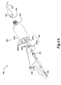
- FIGURES 4A and 4B are diagrams illustrating components of the optical pen 220 of FIGURES 3A and 3B , for an embodiment that includes an exemplary repeatable fast exchange mount 285.
- the optical pen 220 includes a base member 282 and an interchangeable optics element 280.
- the interchangeable optics element 280 includes a front plate 286, tube 231, and chromatically dispersive optical portion 250.
- the base member 282 includes a base housing 282A which includes a surface which serves as a first mating half 285A of the repeatable fast exchange mount 285, and the front plate 286 has a corresponding surface which serves as a second mating half 285B of the repeatable fast exchange mount 285.
- the second mating half 285B of the repeatable fast exchange mount 285 is magnetically forced against the first mating half285A by permanent magnets 285C mounted in one or both of the first and second mating halves 285A or 285B.
- the second mating half 285B may be automatically connected to and separated from the first mating half 285A under program control (e.g., as controlled by the computer and user interface 206).
- the optical pen may include a collar 232 or the like, which may be guided under program control such that it is inserted between the arms of a mating fork included on a probe rack within the motion volume of a CMM.
- the CMM may then move the CRS probe 215' such that the arms of the fork bear on the collar 232 and force the mating halves of the repeatable fast exchange mount 285 apart, leaving the interchangeable optics element 280 hanging in the probe rack.
- the interchangeable optics element 280 may be mounted back to the base member 282 by the reverse of these operations.
- the interchangeable optics element 280 will separate from the base member 282, rather than being damaged.
- the repeatable fast exchange mount 285 may comprise three spheres or balls 285D which are fixed in the first mating half 285A in a first triangular pattern (e.g., an equilateral triangle), and a three radially oriented V-grooves 285E which are fixed in the second mating half 285B in a mating pattern.
- a first triangular pattern e.g., an equilateral triangle
- a three radially oriented V-grooves 285E which are fixed in the second mating half 285B in a mating pattern.
- Such an embodiment of the repeatable fast exchange mount 285 allows the interchangeable optics element 280 to be mounted with the laterally oriented measurement beam 296 facing in any of three different orientations spaced 120 degrees apart.
- Such an embodiment is exemplary only, and not limiting.
- Various other repeatable fast exchange mounting configurations may be used, provided that adequate mounting repeatability is provided, as is generally known in the art.
- the interchangeable optics element 280 includes the chromatically dispersive optical portion 250 (e.g., analogous to the chromatically dispersive optical portion 150 described above with respect to FIGURE 1 ).
- the base member 282 includes the end of an optical fiber 212 that is connected to the LED light source 264 and to the spectrometer arrangement 262' through a fiber connector 261.
- the end of the optical fiber may be located proximate to a confocal aperture 295 that is fixed relative to the first mating half 285A of the repeatable fast exchange mount 285, which may generally surround the confocal aperture 295.
- the end of the optical fiber provides the confocal aperture.
- the confocal aperture 295 is provided by a thin aperture that is bonded in place proximate to or abutting the end of the optical fiber (e.g., on a holder or connector that holds the optical fiber).
- the base member 282 includes an optical fiber locating element 283 (e.g., a fiber optic connector that mates with the connector 209, in this embodiment) that is fixed (e.g., bonded) in the base member 242 proximate to the first mating half285A of the repeatable fast exchange mount 285.
- the optical fiber locating element 283 fixes the end of the optical fiber and the confocal aperture 295 relative to the first mating half 285A of the repeatable fast exchange mount 285.
- the confocal aperture may be separately fixed to the base member 282 and the end of the optical fiber may be fixed proximate to that confocal aperture by a suitable optical fiber locating element, if desired.
- the interchangeable optics element 280 receives measurement light from, and returns measurement light to, the confocal aperture 295, and provides axial chromatic dispersion of the measurement light over a respective measuring range along a measuring axis.
- the chromatically dispersive optical portion 250 may also include a reflective element 294, which directs the measurement beam laterally to the axis of the optical pen 220 (e.g., laterally relative to the axis of the tube 231).
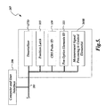
- FIGURE 5 is a block diagram of one embodiment of the computer and user interface 206 and the probe signal processing and control circuit 207 of FIGURE 2 .
- the probe signal processing and control circuit 207 may include a deserializer 5277D, a position latch 515, a CRS probe ID 520 and an optical pen ID 525.
- the components of the probe signal processing and control circuit 207 are coupled to one another and to the computer and user interface 206 by the data transfer line 201.
- the deserializer 277D may work in conjunction with the serializer 277S shown in FIGURE 3A , to allow various data signals to be serialized and communicated through the autojoint connection 230 using relatively few wires.
- the serializer 277S and a deserializer 277D are related to the utilization of certain low voltage differential signaling (LVDS) that may be used in some embodiments, as will be described in more detail below with respect to FIGURE 7 .
- LVDS low voltage differential signaling
- a synchronization signal is provided between a serializer and a deserializer, in order to ensure that they are synchronized.
- clock signals are provided until the deserializer is finished, at which point the synchronization signal is switched, after which the relevant data signals are provided on the signal lines (i.e., as opposed to the previous clock signals).
- the position latch 515 relates to an XYZ latch signal that will be described in more detail below with respect to FIGURE 7 .
- an XYZ latch signal is provided for synchronizing the measurement positioning of the CRS probe with the measurement positioning of the coordinate measurement machine controller 202.
- the position latch 515 communicates with the position latch 204 in the coordinate measurement machine controller 202 in order to ensure that the coordinates of the coordinate measurement machine 210 are properly synchronized.
- the position latch 515 and the position latch 204 combine to ensure the accuracy of the overall derived measurements, such that the CMM machine coordinates (which reflect the position of the CRS probe during a particular measurement) are properly combined with the CRS probe measurements (which are relative to the CRS probe position).
- the CRS probe ID 520 is utilized for determining the identification of the CRS probe 215' (e.g., by reading and processing an identification signal derived from an identifying element included in the CRS probe 215'), and the optics elements ID 525 is utilized for determining the identification of the interchangeable optics element 280 (e.g., by reading and processing an identification signal derived from an identifying element included in the interchangeable optics element 280).
- the proper identification of the CRS probe 215' and the interchangeable optics element 280 allow proper configuration and calibration data to be utilized in order to ensure accurate operations and resulting measurements from the CRS probe 215' and interchangeable optics element 280.
- FIGURE 6 is a diagram illustrating a cross section of the probe data cable 211 of FIGURE 2 .
- the probe data cable 211 includes a sheath 605, sealing tape layers 610, an electrical outer shield layer 615 and a coaxial cable 620 including a central conductor "1" and an inner shield layer 625. Additional conductors 2 through 14 are shown as surrounding the coaxial cable 620, in accordance with a conventional RenishawTM configuration, as will be described in more detail below with respect to FIGURE 7 .
- FIGURE 7 is a table 700 outlining one exemplary connection and/or signal scheme usable with the probe data cable 211 of FIGURE 6 and /or the autojoint connection 230 shown in FIGURES 3A and 3B .
- the connection numbers in the "Wire #" column indicate the wire number of the cable 211 that is connected to an auto joint pin (e.g., one standard RenishawTM autojoint connection configuration), unless otherwise indicated.
- power and signal ground connections may be provided on the various wires and connected auto joint pins.
- LVDS low voltage differential signaling
- SERDES+, SERDES- and SERDES block/sync may be provided on the various wires and connected auto joint pins.
- CRS control clock and data signals e.g., I 2 C clock and data signals
- a plurality of wires may be used in combination to provide power to the CRS CMM probe, in order to meet certain standard autojoint and/or CMM controller design requirements (e.g., not providing more than 300 mA through any single conductor). For example, using two wires at 12 V, 300 mA each provides the capability of delivering 7.2 watts within standard autojoint and/or CMM controller specifications.
- the various signals may be routed on any suitable wire and/or autojoint pin.
- the serializer signals SERDES+ , SERDES- are carried on lines/pins that connect the deserializer 277D and serializer 277S. Experiment and/or analysis may be used to select and/or verify the connections that provide reliable signal transmission.
- a position D0 is designated as being for the detector pixel clock.
- a position D1 is designated as being for the profile start signal for the spectral profile measurement data.
- a position D2 is designated as being for the spectrometer ready signal.
- the position D3 is designated as being for the XYZ latch signal (e.g., as described in more detail above with respect to the position latch 515 of FIGURE 5 ).
- a position D4 is designated as being for a detector temperature alarm.
- the position D5 is designated as being for a spectrometer temperature alarm.
- the positions D6-D9 are not yet designated and thus are not specifically assigned in this embodiment.
- the fastest available digital signal may be utilized (e.g., a detector pixel clock signal at several MHz).
- the serializer may then sample the digital signals at a relatively fast rate (e.g., two times the detector pixel clock rate).
- the LVDS serializer may sample up to 10 digital signals per sample cycle.
- the serializer may then transmit the combined signals at a much faster rate (e.g., 2 times the detector pixel clock rate times ⁇ 10 digital signals + 2 synchronization bits>), which may provide a bit rate of more than 100MHz, in some embodiments.
- LVDS serializer low voltage differential signaling serializer
- the standard autojoint connector only provides a limited number of connections (e.g., 13 pins).
- a standard CRS system may utilize significantly more conductors, such as between the controller and the spectrometer (e.g., 24 conductors). The conductor count can be reduced in part by avoiding non-crucial signals.
- the LVDS serializer technique allows more signals to be provided to the controller board using only two signal lines, as described above with respect to FIGURE 7 .
- Such LVDS serialization techniques may provide at least three or more distinct signals over two connections/conductors through the auto exchange joint element, and in some embodiments up to 10 digital signals or types of information using only two conductors through the auto exchange joint element.
- the signals are made to be robust, in that the differential signals ignore common mode noise.
- the technique may be implemented with low power (e.g., in one specific example embodiment the signals may be sent at +/- 500mV with a 1V offset), which is important in a CMM probe application.
- a high speed can be achieved (e.g., a range of 100 MHz to GHz operation).
- the signals may travel over relatively long wires (e.g., multiple meters of wire when proper termination is utilized).
- the LVDS serialization techniques may be implemented using a SN65LV1023 serializer and SN67LV1224 deserializer from Texas Instrument of Dallas, Texas, USA.
- the signaling protocol outlined above, or other known LVDS signaling protocols, may be used.
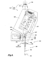
- FIGURE 8 is a diagram schematically illustrating components and optical paths usable in a second exemplary embodiment of the CRS probe of FIGURE 2 in which the light used in the CRS probe assembly propagates in free space through optical elements mounted in a fixed relationship, rather than through an optical fiber.
- the CRS probe 815' includes auto exchange joint element 236 and a probe assembly 816 that is mounted to the auto exchange joint element 236, for automatic connection to the CMM through the probe autojoint connection 230.
- the probe 815' may also include a protective cover or housing (not shown).
- the probe assembly 816 comprises an optical pen 820, an electrically powered light source 864, and a wavelength detector 862 supported by a frame 819 which may include various structural members, and which may extend from a base 818 that is attached to the auto exchange joint element 236.
- the frame 819 holds the various elements outlined above, as well as a set of optical path elements (e.g., lenses, a beamsplitter, etc.), in a fixed relationship that provides the desired optical path for the light used in the probe assembly 816.
- the optical pen 820 (analogous to the optical pen 220) may include a confocal optical path including an aperture 895 and chromatically dispersive optics portion 850, which outputs a measurement beam 896.
- the optical pen 820 may include a repeatable fast exchange mount 885 which allows replacement of the chromatically dispersive optics portion 850, as outlined above in relation to the repeatable fast exchange mount 285.
- the electrically powered light source 864 receives electrical power transmitted through the auto exchange joint element and generates light originating in the CRS probe assembly, the light comprising an input spectral profile of wavelengths.
- the input spectral profile is output through light source optics 844 which may provide a focused and/or shaped input beam 845.
- the input beam 845 is reflected at a beam splitter 846 along the beam path 847 to confocal aperture 895 of the optical pen 820.
- the optical pen transmits and outputs corresponding radiation to the workpiece surface in the measurement beam 896 and receives reflected radiation from the workpiece surface and outputs reflected radiation from the confocal aperture 895 back along the beam path 847 and through the beamsplitter 846 to provide an output spectral profile 848 to the spectrometer input optics 849 and to the spectrometer 862' of the CRS wavelength detector 862.
- the output spectral profile comprises a distance-dependent profile component having a wavelength peak that indicates a measurement distance from the optical pen to the workpiece surface, and the CRS wavelength detector provides corresponding output spectral profile data (e.g., output by electrical signals through the probe autojoint connection 230) according to previously outlined principles of operation for a CRS probe.
- a configuration such as that outlined above which generates and processes the light used for measurement entirely within the CRS probe assembly allows the CRS probe assembly 815' to be self-contained and automatically exchangeable.
- a CRS probe system does not require or include an optical fiber connection from the CRS probe assembly to an outside element through the auto joint connector, or along any other makeshift path in parallel with the auto joint connector.
- such a CRS probe assembly does not connect to or include an optical fiber that extends outside of the CRS probe assembly.
- the center of mass of the optical pen 820 may be located proximate to an axis defined by the center of mass of the rest of the CRS probe 815' and the center axis of the probe autojoint connection 230.
- the optical pen 820 may also be mounted relative to the probe autojoint connection 230 such that the central axis of the optical pen 220 is coaxial with the central axis of the probe autojoint connection 230.
- the optical pen 820 may include a repeatable fast exchange mount 885, which may be designed according to previously outlined principles, for example including a base member 882 and an interchangeable optics element 880.
- FIGURE 9 is a flow diagram illustrating one exemplary embodiment of a routine 900 for providing and operating an automatically interchangeable CRS probe system embodiment as disclosed herein.
- a CRS probe system is provided that is capable of being automatically connected to a CMM under program control.
- the CRS probe system includes an auto exchange joint element which is attachable through a standard auto exchange joint connection to a CMM, and a CRS probe assembly that is mounted to the auto exchange joint element for automatic connection to the CMM through the auto exchange joint element.
- such a CRS probe system does not require or include an optical fiber connection from the CRS probe assembly to an outside element through the auto joint connector, or along any other makeshift path in parallel with the auto joint connector.
- the CRS probe assembly includes an optical pen, an electrically powered light source which receives electrical power transmitted through the auto exchange joint element and generates light originating in the CRS probe assembly, and a CRS wavelength detector.
- the optical pen comprises a confocal optical path including a chromatically dispersive optics portion, the optical pen configured to focus different wavelengths at different distances along a measurement axis proximate to a workpiece surface to be measured.
- the light originating in the CRS probe assembly comprises an input spectral profile of wavelengths routed to the optical pen.
- the CRS wavelength detector comprises a plurality of pixels distributed along a measurement axis of the CRS wavelength detector, the plurality of pixels receiving respective wavelengths and providing output spectral profile data.
- the CRS probe system is connected to a CMM through the auto exchange joint element and power and control signals are provided to the CRS probe assembly through the auto exchange joint connection.
- the optical pen is operably positioned relative to a workpiece surface, and the CRS probe system is operated to perform measurement operations wherein: the electrically powered light source generates the light, the optical pen inputs the input spectral profile and outputs corresponding radiation to the workpiece surface and receives reflected radiation from the workpiece surface and outputs reflected radiation to provide an output spectral profile to the CRS wavelength detector.
- the output spectral profile comprises a distance-dependent profile component having a wavelength peak that indicates a measurement distance from the optical pen to the workpiece surface.
- the CRS wavelength detector provides corresponding output spectral profile data as part of the measurement operations.
- the CRS probe assembly is operated to output measurement signals based on the output spectral profile data, wherein the output measurement signals are indicative of a measurement distance to the workpiece surface.
- the output spectral profile data as provided by the pixel values of a detector array included in the wavelength detector are the output measurement signals.
- the output measurement signals may be signals derived from the measured spectral profile data (e.g., compensated signals, or a determined wavelength peak value, or a final distance measurement derived therefrom, or the like).
- the output measurement signals are carried on at least one conductor through the auto exchange joint element.
- some or all of the signals may be wirelessly transmitted, and bypass the probe autojoint connection. It will be appreciated that the feature of the CRS probe configurations disclosed herein that allows them to be self-contained and automatically exchangeable is that they are configured to generate and process the light used for measurement entirely within the CRS probe assembly.
- control and data signals that are output in the form of signals conducted through the probe autojoint connection 230
- some or all of the signals could be wirelessly transmitted, and bypass the probe autojoint connection 230.
- the feature of the CRS probe configurations disclosed herein that allows them to be self-contained and automatically exchangeable is that they are configured to generate and process the light used for measurement entirely within the CRS probe assembly. After the light is processed to determine the output spectral profile data, it may be wirelessly transmitted to avoid extraneous optical fiber connections outside of the CRS probe assembly, if desired.
Claims (15)
- Sondensystem (215, 215', 815') für Sensor mit chromatischem Bereich (CRS), das automatisch mit einer Koordinatenmessmaschine (CMM) (210, 202) programmgesteuert verbunden werden kann, wobei das CRS-Sondensystem (215, 215', 815') umfasst.
ein Automatikwechsel-Aufnahmeelment (236), das durch einen standardmäßige Automatikwechsel-Aufnahmeverbindung (234) an einer CMM (210, 202) angebracht werden kann; und
eine CRS-Sondenbaugruppe (216, 816), die an dem Automatikwechsel-Aufnahmeelement (236) befestigt ist, für die automatische Verbindung mit der CMM (210, 202) durch das Automatikwechsel-Aufnahmeelement (236),
dadurch gekennzeichnet. dass
die CRS-Sondenbaugruppe umfasst:einen Lesestift (220, 820), der einen konfokalen Strahlengang mit einem chromatisch dispersiven Optikteil (250, 850) umfasst, wobei der Lesestift (220, 820) dazu ausgebildet ist, unterschiedliche Wellenlängen bei unterschiedlichen Abständen entlang einer Messachse unmittelbar an einer zu messenden Werkstückoberfläche zu fokussieren;eine elektrisch gespeiste Lichtquelle (264, 864), die durch das Automatikwechsel-Aufnahmeelement (236) übertragene elektrische Energie empfängt und Licht erzeugt, das von der CRS-Sondenbaugruppe stammt, wobei das Licht ein Eingangsspektralprofil von Wellenlängen umfasst, das zum Lesestift (220, 820) geleitet wird; undeinen CRS-Wellenlängendetektor (262, 862), der ein Spektrometer oder eine Spektrographanordnung (262') umfasst, wobei ein dispersiver Teil ein spektrales Intensitätsprofil an mehrere Pixel (263) überträgt, die entlang einer Messachse des CRS-Wellenlängendetektors (262, 862) verteilt sind, wobei die mehreren Pixel (263) jeweilige Wellenlängen empfangen und Ausgangsspektralprofildaten bereitstellen,wobei die CRS-Sondenbaugruppe dazu ausgebildet ist, Strom und Steuersignale durch die Automatikwechsel-Aufnahmeverbindung (234, 235) zu empfangen;die CRS-Sondenbaugruppe derart ausgebildet ist, dass, wenn das Automatikwechsel-Aufnahmeelement (236) an einer CMM (210, 202) angebracht ist und der Lesestift (220, 820) betriebsbereit relativ zu einer Werkstückoberfläche positioniert ist, um Messbetriebe auszuführen, und die elektrisch gespeiste Lichtquelle das Licht erzeugt, der Lesestift (220, 820) das Eingangsspektralprofil eingibt, entsprechende Strahlung (296, 896) an die Werkstückoberfläche ausgibt, reflektierte Strahlung von der Werkstückoberfläche empfängt und reflektierte Strahlung aus dem konfokalen Strahlengang ausgibt, um ein Ausgangsspektralprofil an den CRS-Wellenlängendetektor (262, 862) bereitzustellen, wobei das Ausgangsspektralprofil eine abstandsabhängige Profilkomponente mit einer Wellenlängenspitze umfasst, die einen Messabstand von dem Lesestift (220, 820) zur Werkstückoberfläche anzeigt, und der CRS-Wellenlängendetektor (262, 862) entsprechende Ausgangsspektralprofildaten bereitstellt; unddie CRS-Sondenbaugruppe dazu ausgebildet ist, Messsignale auf der Basis der Ausgangsspektralprofildaten auszugeben, wobei die Ausgangsmesssignale einen Messabstand zur Werkstückoberfläche anzeigen. - System nach Anspruch 1, wobei die Ausgangsmesssignale die Ausgangsspektralprofildaten von den mehreren Pixel (263) des CRS-Wellenlängendetektors (262, 862) umfasst.
- System nach Anspruch 2, wobei die Ausgangsmesssignale über mindestens einen Leiter (211, 620) durch das Automatikwechsel-Aufnahmeelement (236) geführt werden und durch das Automatikwechsel-Aufnahmeelement von einer Sondensignalverarbeitungs- und Steuerschaltung (207) empfangen werden, die Messabstände basierend auf den Ausgangsspektralprofildaten bestimmt.
- System nach Anspruch 1, wobei die CRS-Sondenbaugruppe (216, 816) ferner eine Identifizierungskomponente umfasst, die Sondenidentifizierungsdaten bereitstellt, die an mindestens eine von der CMM (210, 202) und einer Sondensignalverarbeitungs- und Steuerschaltung (207, 520) ausgegeben werden.
- System nach Anspruch 1, wobei mindestens eines von Kalibrierdaten oder Kompensationsdaten für die CRS-Sondenbaugruppe (216, 816) gespeichert ist in mindestens einem von:der CMM (210, 202);einer Sondensignalverarbeitungs- und Steuerschaltung (207), die Signale von der CRS-Sondenbaugruppe empfängt; undeinem Speicherteil (168) der CRS-Sonde (215, 215', 216, 816).
- System nach Anspruch 1, wobei sich der Massenschwerpunkt des Lesestifts (220, 820) unmittelbar an einer Achse befindet, die durch den Massenschwerpunkt (CMPA) der CRS-Sondenbaugruppe (216, 816) und der Mitte der Automatikwechselaufnahme (230, 236) definiert wird.
- System nach Anspruch 1, wobei der Lesestift (220, 820) relativ zu der Automatikwechselaumahme (230, 236) derart befestigt ist, dass die Mittenachse (CAOP) des Lesestifts koaxial zu einer Mittenachse (CAJ) der Automatikwechselaufnahme (230, 236) ist, derart, dass, wenn die CMM (210, 202) die Automatikwechselaufnahme um ihre Mittenachse rotiert, der Lesestift (220, 820) um seine Mittenachse (CAOP) rotiert wird, ohne wesentliche seitliche Bewegung der Mittenachse des Lesestifts aufgrund der Rotation.
- System nach Anspruch 1, wobei der Lesestift (220, 820) ein austauschbares Optikelement (280, 880) umfasst, das den chromatisch dispersiven Optikteil (250, 850) enthält, und der Lesestift (220, 820) ferner ein Lesestift-Basisteil (282, 882) umfasst, das das austauschbare Optikelement aufnimmt und in einer festen Beziehung relativ zu dem Basisteil hält.
- System nach Anspruch 8, wobei das Lesestift-Basisteil (282, 882) umfasst:ein Gehäuse (282A) mit einer ersten Paarungshälfte (285A) einer reproduzierbaren Schnellwechselhalterung (285) und das Ende einer Lichtleitfaser (212), die mit der Lichtquelle (264, 864) und dem Wellenlängendetektor (262, 862) verbunden ist, wobei die Lichtleitfaser (212) unmittelbar an einer konfokalen Blende (295) endet, die relativ zur ersten Paarungshälfte (285A) der reproduzierbaren Schnellwechselhalterung (285) fixiert ist.
- System nach Anspruch 9, wobei die erste Paarungshälfte (285A) der reproduzierbaren Schnellwechselhalterung (285) im Allgemeinen die konfokale Blende (295) umgibt.
- System nach Anspruch 10, wobei das austauschbare Optikelement (280) umfasst:eine zweite Paarungshälfte (285B) der reproduzierbaren Schnellwechselhalterung (285); undeine optische Baugruppe, die relativ zur zweiten Paarungshälfte (285B) der reproduzierbaren Schnellwechselhalterung (285) fixiert ist, die den chromatisch dispersiven Optikteil (250, 850) umfasst, wobei die optische Baugruppe Messlicht von der konfokalen Blende (295) empfängt und Messlicht an sie zurückgibt, und axiale chromatische Dispersion des Messlichts über einen jeweiligen Messbereich (R, R') entlang einer Messachse (MA, MA') bereitstellt.
- System nach Anspruch 11, wobei die zweite Paarungshälfte (285B) der reproduzierbaren Schnellwechselhalterung (285) ausgebildet ist, um programmgesteuert automatisch mit der ersten Paarungshälfte (285A) der reproduzierbaren Schnellwechselhalterung (285) verbunden und von ihr getrennt zu werden; und
die zweite Paarungshälfte (285B) der reproduzierbaren Schnellwechselhalterung (285) durch einen Permanentmagnet (285C), der in einer von der ersten und der zweiten Paarungshälfte der reproduzierbaren Schnellwechselhalterung (285) befestigt ist, magnetisch gegen die erste Paarungshälfte (285A) der reproduzierbaren Schnellwechselhalterung (285) gezogen wird. - System nach Anspruch 1, wobei:die CRS-Sondenbaugruppe (216, 816) derart ausgebildet ist, dass der Lesestift (220, 820) an einem distalen Ende der CRS-Solidenbaugruppe (216, 816) befestigt ist;die CRS-Sondenbaugruppe (216, 816) umfasst:einen Basisteil (218, 818), der an dem Automatikwechsel-Aufnahmeelement (236) befestigt ist;einen Wellenlängendetektor-Befestigungsteil (219A), der an den Basisteil gekoppelt ist;einen Lesestift-Befestigungsteil (219B), der an den Basisteil gekoppelt ist und den Lesestift (220, 820) trägt, ohne den Wellenlängendetektor (262, 862) zu tragen; undder Lesestift-Befestigungsteil (219B) ein hohles Strukturrohr umfasst, das sich von dem Basisteil weg und in Richtung auf das distale Ende der CRS-Sondenbaugruppe (216, 816) erstreckt.
- System nach Anspruch 1, wobei ein Niederspannung-Differentialsignalisierung (LVDS)-Serialisierer (277S) genutzt wird, um drei oder mehr eindeutige Signale (SERDES+, SERDES-) über zwei Verbindungen (2-14 von 211) durch das Automatikwechsel-Aufnahmeelement (236) bereitzustellen.
- System nach Anspruch 1, wobei ein XYZ-Latch-Signal bereitgestellt wird, um die Messpositionierung des CRS-Sondensystems (215, 215', 815') mit der Messpositionierung der CMM (210, 202) zu synchronisieren.
Applications Claiming Priority (1)
| Application Number | Priority Date | Filing Date | Title |
|---|---|---|---|
| US13/481,734 US8736817B2 (en) | 2012-05-25 | 2012-05-25 | Interchangeable chromatic range sensor probe for a coordinate measuring machine |
Publications (2)
| Publication Number | Publication Date |
|---|---|
| EP2667152A1 EP2667152A1 (de) | 2013-11-27 |
| EP2667152B1 true EP2667152B1 (de) | 2015-04-15 |
Family
ID=48485042
Family Applications (1)
| Application Number | Title | Priority Date | Filing Date |
|---|---|---|---|
| EP20130169336 Active EP2667152B1 (de) | 2012-05-25 | 2013-05-27 | Austauschbare Sonde eines Sensors mit chromatischem Bereich für eine Koordinatenmessmaschine |
Country Status (3)
| Country | Link |
|---|---|
| US (2) | US8736817B2 (de) |
| EP (1) | EP2667152B1 (de) |
| CN (1) | CN103424073B (de) |
Cited By (1)
| Publication number | Priority date | Publication date | Assignee | Title |
|---|---|---|---|---|
| EP3306263A1 (de) | 2016-10-04 | 2018-04-11 | Precitec Optronik GmbH | Chromatisch-konfokaler abstandssensor |
Families Citing this family (23)
| Publication number | Priority date | Publication date | Assignee | Title |
|---|---|---|---|---|
| US8736817B2 (en) | 2012-05-25 | 2014-05-27 | Mitutoyo Corporation | Interchangeable chromatic range sensor probe for a coordinate measuring machine |
| DE102013105753B3 (de) * | 2013-06-04 | 2014-10-02 | Carl Zeiss Industrielle Messtechnik Gmbh | Verfahren zum automatischen Aufnehmen eines Sensorkopfs und Koordinatenmessgerät |
| US9772173B2 (en) * | 2013-06-27 | 2017-09-26 | Faro Technologies, Inc. | Method for measuring 3D coordinates of a surface with a portable articulated arm coordinate measuring machine having a camera |
| DE102013113265B4 (de) * | 2013-11-29 | 2019-03-07 | Grintech Gmbh | Vorrichtung zur berührungslosen optischen Abstandsmessung |
| US9402070B2 (en) | 2014-06-12 | 2016-07-26 | Faro Technologies, Inc. | Coordinate measuring device with a six degree-of-freedom handheld probe and integrated camera for augmented reality |
| US10021379B2 (en) | 2014-06-12 | 2018-07-10 | Faro Technologies, Inc. | Six degree-of-freedom triangulation scanner and camera for augmented reality |
| US10176625B2 (en) | 2014-09-25 | 2019-01-08 | Faro Technologies, Inc. | Augmented reality camera for use with 3D metrology equipment in forming 3D images from 2D camera images |
| CN105486251B (zh) * | 2014-10-02 | 2019-12-10 | 株式会社三丰 | 形状测定装置、形状测定方法及点感测器的定位单元 |
| US9506744B2 (en) | 2014-12-16 | 2016-11-29 | Faro Technologies, Inc. | Triangulation scanner and camera for augmented reality |
| US11520472B2 (en) * | 2015-09-24 | 2022-12-06 | Mitutoyo Corporation | Inspection program editing environment including integrated alignment program planning and editing features |
| KR102479184B1 (ko) | 2015-12-07 | 2022-12-19 | 삼성전자주식회사 | 프로브 교환 장치 및 방법 |
| DE202016006669U1 (de) * | 2016-10-26 | 2017-08-29 | Tesa Sa | Optischer Sensor mit variierbaren Messkanälen |
| CN106767573A (zh) * | 2017-03-24 | 2017-05-31 | 合肥工业大学 | 一种基于色散共焦光谱法的表面粗糙度测量系统及其方法 |
| JP7053671B2 (ja) * | 2017-06-30 | 2022-04-12 | 株式会社ミツトヨ | 座標測定機用の自己構成要素識別および信号処理システム |
| EP3688404B1 (de) | 2017-09-29 | 2023-06-07 | Mitutoyo Corporation | Kompakte messanordnungskonfiguration zur integration von komplexen schaltungen |
| US11313671B2 (en) * | 2019-05-28 | 2022-04-26 | Mitutoyo Corporation | Chromatic confocal range sensing system with enhanced spectrum light source configuration |
| EP4018157A4 (de) * | 2019-09-18 | 2023-08-30 | DWFritz Automation, Inc. | Berührungslose optische messvorrichtungen und austauschbare optische sonden |
| CN110553604A (zh) * | 2019-10-16 | 2019-12-10 | 合肥学院 | 一种水轮机叶片毛坯型面测量与加工余量分析方法 |
| US11118896B2 (en) * | 2019-11-27 | 2021-09-14 | Mitutoyo Corporation | Configuration for coupling chromatic range sensor optical probe to coordinate measurement machine |
| US11499817B2 (en) | 2020-05-29 | 2022-11-15 | Mitutoyo Corporation | Coordinate measuring machine with vision probe for performing points-from-focus type measurement operations |
| US11328409B2 (en) | 2020-09-30 | 2022-05-10 | Mitutoyo Corporation | System and method utilizing multi-point autofocus to align an optical axis of an optical assembly portion to be normal to a workpiece surface |
| US11486694B2 (en) | 2020-12-18 | 2022-11-01 | Mitutoyo Corporation | Chromatic range sensor system for measuring workpiece thickness |
| EP4019949A1 (de) | 2020-12-24 | 2022-06-29 | Inel S.A.S | Verfahren und system zur charakterisierung von materialien unter verwendung mehrerer instrumente und datenfusion |
Family Cites Families (49)
| Publication number | Priority date | Publication date | Assignee | Title |
|---|---|---|---|---|
| DE3320127C2 (de) | 1983-06-03 | 1994-09-08 | Zeiss Carl Fa | Taststiftwechselhalter |
| GB8330412D0 (en) | 1983-11-15 | 1983-12-21 | Renishaw Plc | Tool change apparatus |
| WO1989005210A1 (en) | 1987-12-05 | 1989-06-15 | Renishaw Plc | Apparatus for changing a sensing device |
| DE3806686A1 (de) | 1988-03-02 | 1989-09-14 | Wegu Messtechnik | Mehrkoordinatenmess- und -pruefeinrichtung |
| EP0415579A1 (de) | 1989-08-30 | 1991-03-06 | Renishaw plc | Berührender Taster |
| US5505005A (en) | 1990-02-23 | 1996-04-09 | Renishaw Plc | Touch probe |
| US5339535A (en) | 1990-02-23 | 1994-08-23 | Renishaw Metrology Limited | Touch probe |
| DE4330873A1 (de) | 1993-09-13 | 1995-03-16 | Zeiss Carl Fa | Koordinatenmeßgerät mit einem Tastkopf und einer Elektronik zur Verarbeitung des Tastsignals |
| US5825666A (en) | 1995-06-07 | 1998-10-20 | Freifeld; Daniel | Optical coordinate measuring machines and optical touch probes |
| US5705814A (en) | 1995-08-30 | 1998-01-06 | Digital Instruments, Inc. | Scanning probe microscope having automatic probe exchange and alignment |
| US5657549A (en) | 1995-10-04 | 1997-08-19 | Shen; Yin-Lin | Method of improving accuracy of touch trigger probe |
| US6093930A (en) | 1998-04-02 | 2000-07-25 | International Business Machnines Corporation | Automatic probe replacement in a scanning probe microscope |
| GB9813263D0 (en) | 1998-06-20 | 1998-08-19 | Renishaw Plc | Touch probe |
| GB9907644D0 (en) | 1999-04-06 | 1999-05-26 | Renishaw Plc | Surface sensing device with optical sensor |
| DE10006753A1 (de) | 2000-02-15 | 2001-08-16 | Zeiss Carl | Dreh-Schwenkeinrichtung für den Tastkopf eines Koordinatenmeßgerätes |
| GB0106870D0 (en) | 2001-03-20 | 2001-05-09 | Renishaw Plc | Disconnectable joint |
| DE10220824B4 (de) | 2001-05-14 | 2010-08-05 | Robert Bosch Gmbh | Optische Messvorrichtung |
| GB0115788D0 (en) | 2001-06-28 | 2001-08-22 | Renishaw Plc | Tool identification |
| WO2003009305A2 (en) | 2001-07-18 | 2003-01-30 | The Regents Of The University Of California | Measurement head for atomic force microscopy and other applications |
| GB0129471D0 (en) | 2001-12-10 | 2002-01-30 | Renishaw Plc | Rack and change system |
| US6677567B2 (en) | 2002-02-15 | 2004-01-13 | Psia Corporation | Scanning probe microscope with improved scan accuracy, scan speed, and optical vision |
| DE10301607B4 (de) | 2003-01-17 | 2005-07-21 | Robert Bosch Gmbh | Interferenzmesssonde |
| DE102004011189B4 (de) | 2004-03-04 | 2011-05-05 | Carl Mahr Holding Gmbh | Optischer Messkopf |
| EP1754018B1 (de) | 2004-06-08 | 2018-07-11 | Micro-Epsilon Messtechnik GmbH & Co. KG | Vorrichtung und verfahren zum prüfen von oberflächen im inneren von löchern |
| GB0518153D0 (en) | 2005-09-07 | 2005-10-12 | Rolls Royce Plc | Apparatus for measuring wall thicknesses of objects |
| US7652275B2 (en) | 2006-07-28 | 2010-01-26 | Mitutoyo Corporation | Non-contact probe control interface |
| JP2010502953A (ja) | 2006-08-31 | 2010-01-28 | ファロ テクノロジーズ インコーポレーテッド | 知的プローブ |
| US8099793B2 (en) | 2006-12-21 | 2012-01-17 | Park Systems Corp. | Scanning probe microscope with automatic probe replacement function |
| US7626705B2 (en) | 2007-03-30 | 2009-12-01 | Mitutoyo Corporation | Chromatic sensor lens configuration |
| EP2037214A1 (de) | 2007-09-14 | 2009-03-18 | Leica Geosystems AG | Verfahren und Messgerät zum vermessen von Oberflächen |
| EP2042829B2 (de) | 2007-09-26 | 2017-08-09 | Hexagon Metrology AB | Modulare Kalibrierung |
| DE202007014435U1 (de) | 2007-10-16 | 2009-03-05 | Gurny, Eric | Optischer Sensor für eine Messvorrichtung |
| US7990522B2 (en) | 2007-11-14 | 2011-08-02 | Mitutoyo Corporation | Dynamic compensation of chromatic point sensor intensity profile data selection |
| DE102007054915A1 (de) | 2007-11-15 | 2009-05-20 | Precitec Optronik Gmbh | Messvorrichtung, Messkopf und Messkopfhalter |
| US7921575B2 (en) | 2007-12-27 | 2011-04-12 | General Electric Company | Method and system for integrating ultrasound inspection (UT) with a coordinate measuring machine (CMM) |
| EP2161536A1 (de) | 2008-09-05 | 2010-03-10 | Leica Geosystems AG | Optischer Sensor mit Kollisionsschutz für eine Messmaschine |
| US7908757B2 (en) | 2008-10-16 | 2011-03-22 | Hexagon Metrology, Inc. | Articulating measuring arm with laser scanner |
| EP2194357A1 (de) | 2008-12-03 | 2010-06-09 | Leica Geosystems AG | Optisches Sensorelement für eine Messmaschine, und messmaschinenseitiges Kupplungselement hierfür |
| US7876456B2 (en) | 2009-05-11 | 2011-01-25 | Mitutoyo Corporation | Intensity compensation for interchangeable chromatic point sensor components |
| US20110080588A1 (en) | 2009-10-02 | 2011-04-07 | Industrial Optical Measurement Systems | Non-contact laser inspection system |
| US8677643B2 (en) | 2010-01-20 | 2014-03-25 | Faro Technologies, Inc. | Coordinate measurement machines with removable accessories |
| EP2381212B1 (de) | 2010-04-26 | 2018-04-25 | Tesa Sa | Messsystem für Koordinatenmessung von rotationssymetrischen Messobjekten |
| US8194251B2 (en) * | 2010-08-26 | 2012-06-05 | Mitutoyo Corporation | Method for operating a dual beam chromatic point sensor system for simultaneously measuring two surface regions |
| CN201903324U (zh) * | 2010-11-24 | 2011-07-20 | 西安金和光学科技有限公司 | 光纤型拉线位移传感装置 |
| US8212997B1 (en) | 2011-02-23 | 2012-07-03 | Mitutoyo Corporation | Chromatic confocal point sensor optical pen with extended measuring range |
| US8587789B2 (en) | 2011-12-21 | 2013-11-19 | Mitutoyo Corporation | Chromatic point sensor compensation including workpiece material effects |
| US8860931B2 (en) * | 2012-02-24 | 2014-10-14 | Mitutoyo Corporation | Chromatic range sensor including measurement reliability characterization |
| US8817240B2 (en) | 2012-05-25 | 2014-08-26 | Mitutoyo Corporation | Interchangeable optics configuration for a chromatic range sensor optical pen |
| US8736817B2 (en) | 2012-05-25 | 2014-05-27 | Mitutoyo Corporation | Interchangeable chromatic range sensor probe for a coordinate measuring machine |
-
2012
- 2012-05-25 US US13/481,734 patent/US8736817B2/en active Active
-
2013
- 2013-05-27 EP EP20130169336 patent/EP2667152B1/de active Active
- 2013-05-27 CN CN201310201641.9A patent/CN103424073B/zh active Active
-
2014
- 2014-05-23 US US14/286,913 patent/US9115982B2/en active Active
Cited By (1)
| Publication number | Priority date | Publication date | Assignee | Title |
|---|---|---|---|---|
| EP3306263A1 (de) | 2016-10-04 | 2018-04-11 | Precitec Optronik GmbH | Chromatisch-konfokaler abstandssensor |
Also Published As
| Publication number | Publication date |
|---|---|
| US20140340679A1 (en) | 2014-11-20 |
| US8736817B2 (en) | 2014-05-27 |
| US20130314689A1 (en) | 2013-11-28 |
| CN103424073A (zh) | 2013-12-04 |
| EP2667152A1 (de) | 2013-11-27 |
| US9115982B2 (en) | 2015-08-25 |
| CN103424073B (zh) | 2018-01-12 |
Similar Documents
| Publication | Publication Date | Title |
|---|---|---|
| EP2667152B1 (de) | Austauschbare Sonde eines Sensors mit chromatischem Bereich für eine Koordinatenmessmaschine | |
| EP2667147B1 (de) | Austauschbare Optikkonfiguration für einen Lesestift eines Sensors mit chromatischem Bereich | |
| EP3828493B1 (de) | Konfiguration zur kopplung einer optischen sonde mit chromatischem abstandssensor an eine koordinatenmessmaschine | |
| JP6404014B2 (ja) | クロマティックレンジセンサを構成する光学ペン用の交換可能光学エレメント、および、その分離状態の検出方法 | |
| JP5554459B2 (ja) | 予配置型且つ可換型の光学ベンチを有するジンバル式装置 | |
| WO2013173116A1 (en) | An apparatus and method to compensate bearing runout in laser tracker | |
| US20150260506A1 (en) | Apparatus to compensate bearing runout in a three-dimensional coordinate measuring system | |
| US20080024793A1 (en) | Non-contact probe control interface | |
| US10401165B2 (en) | Articulated head with multiple sensors for measuring machine | |
| WO2015009652A1 (en) | A laser line probe having improved high dynamic range | |
| WO2013188026A1 (en) | Coordinate measurement machines with removable accessories | |
| CN113566699B (zh) | 具有校准对象的旋转色度范围传感器系统和方法 | |
| EP3184957B1 (de) | Modulare mikrooptik für optische sonden | |
| CN113566700B (zh) | 具有校准对象的旋转色度范围传感器系统及方法 | |
| JP2008268000A (ja) | 変位測定方法および装置 |
Legal Events
| Date | Code | Title | Description |
|---|---|---|---|
| PUAI | Public reference made under article 153(3) epc to a published international application that has entered the european phase |
Free format text: ORIGINAL CODE: 0009012 |
|
| AK | Designated contracting states |
Kind code of ref document: A1 Designated state(s): AL AT BE BG CH CY CZ DE DK EE ES FI FR GB GR HR HU IE IS IT LI LT LU LV MC MK MT NL NO PL PT RO RS SE SI SK SM TR |
|
| AX | Request for extension of the european patent |
Extension state: BA ME |
|
| 17P | Request for examination filed |
Effective date: 20140509 |
|
| RBV | Designated contracting states (corrected) |
Designated state(s): AL AT BE BG CH CY CZ DE DK EE ES FI FR GB GR HR HU IE IS IT LI LT LU LV MC MK MT NL NO PL PT RO RS SE SI SK SM TR |
|
| GRAP | Despatch of communication of intention to grant a patent |
Free format text: ORIGINAL CODE: EPIDOSNIGR1 |
|
| RIC1 | Information provided on ipc code assigned before grant |
Ipc: G01B 11/00 20060101ALI20141030BHEP Ipc: G01B 21/04 20060101AFI20141030BHEP |
|
| INTG | Intention to grant announced |
Effective date: 20141125 |
|
| GRAS | Grant fee paid |
Free format text: ORIGINAL CODE: EPIDOSNIGR3 |
|
| GRAA | (expected) grant |
Free format text: ORIGINAL CODE: 0009210 |
|
| AK | Designated contracting states |
Kind code of ref document: B1 Designated state(s): AL AT BE BG CH CY CZ DE DK EE ES FI FR GB GR HR HU IE IS IT LI LT LU LV MC MK MT NL NO PL PT RO RS SE SI SK SM TR |
|
| REG | Reference to a national code |
Ref country code: GB Ref legal event code: FG4D Ref country code: CH Ref legal event code: EP |
|
| REG | Reference to a national code |
Ref country code: IE Ref legal event code: FG4D |
|
| REG | Reference to a national code |
Ref country code: AT Ref legal event code: REF Ref document number: 722240 Country of ref document: AT Kind code of ref document: T Effective date: 20150515 |
|
| REG | Reference to a national code |
Ref country code: DE Ref legal event code: R096 Ref document number: 602013001495 Country of ref document: DE Effective date: 20150528 |
|
| REG | Reference to a national code |
Ref country code: NL Ref legal event code: VDEP Effective date: 20150415 |
|
| REG | Reference to a national code |
Ref country code: AT Ref legal event code: MK05 Ref document number: 722240 Country of ref document: AT Kind code of ref document: T Effective date: 20150415 |
|
| REG | Reference to a national code |
Ref country code: LT Ref legal event code: MG4D |
|
| PG25 | Lapsed in a contracting state [announced via postgrant information from national office to epo] |
Ref country code: NL Free format text: LAPSE BECAUSE OF FAILURE TO SUBMIT A TRANSLATION OF THE DESCRIPTION OR TO PAY THE FEE WITHIN THE PRESCRIBED TIME-LIMIT Effective date: 20150415 |
|
| PG25 | Lapsed in a contracting state [announced via postgrant information from national office to epo] |
Ref country code: HR Free format text: LAPSE BECAUSE OF FAILURE TO SUBMIT A TRANSLATION OF THE DESCRIPTION OR TO PAY THE FEE WITHIN THE PRESCRIBED TIME-LIMIT Effective date: 20150415 Ref country code: FI Free format text: LAPSE BECAUSE OF FAILURE TO SUBMIT A TRANSLATION OF THE DESCRIPTION OR TO PAY THE FEE WITHIN THE PRESCRIBED TIME-LIMIT Effective date: 20150415 Ref country code: LT Free format text: LAPSE BECAUSE OF FAILURE TO SUBMIT A TRANSLATION OF THE DESCRIPTION OR TO PAY THE FEE WITHIN THE PRESCRIBED TIME-LIMIT Effective date: 20150415 Ref country code: ES Free format text: LAPSE BECAUSE OF FAILURE TO SUBMIT A TRANSLATION OF THE DESCRIPTION OR TO PAY THE FEE WITHIN THE PRESCRIBED TIME-LIMIT Effective date: 20150415 Ref country code: PT Free format text: LAPSE BECAUSE OF FAILURE TO SUBMIT A TRANSLATION OF THE DESCRIPTION OR TO PAY THE FEE WITHIN THE PRESCRIBED TIME-LIMIT Effective date: 20150817 Ref country code: NO Free format text: LAPSE BECAUSE OF FAILURE TO SUBMIT A TRANSLATION OF THE DESCRIPTION OR TO PAY THE FEE WITHIN THE PRESCRIBED TIME-LIMIT Effective date: 20150715 |
|
| PG25 | Lapsed in a contracting state [announced via postgrant information from national office to epo] |
Ref country code: GR Free format text: LAPSE BECAUSE OF FAILURE TO SUBMIT A TRANSLATION OF THE DESCRIPTION OR TO PAY THE FEE WITHIN THE PRESCRIBED TIME-LIMIT Effective date: 20150716 Ref country code: IS Free format text: LAPSE BECAUSE OF FAILURE TO SUBMIT A TRANSLATION OF THE DESCRIPTION OR TO PAY THE FEE WITHIN THE PRESCRIBED TIME-LIMIT Effective date: 20150815 Ref country code: LV Free format text: LAPSE BECAUSE OF FAILURE TO SUBMIT A TRANSLATION OF THE DESCRIPTION OR TO PAY THE FEE WITHIN THE PRESCRIBED TIME-LIMIT Effective date: 20150415 Ref country code: RS Free format text: LAPSE BECAUSE OF FAILURE TO SUBMIT A TRANSLATION OF THE DESCRIPTION OR TO PAY THE FEE WITHIN THE PRESCRIBED TIME-LIMIT Effective date: 20150415 Ref country code: AT Free format text: LAPSE BECAUSE OF FAILURE TO SUBMIT A TRANSLATION OF THE DESCRIPTION OR TO PAY THE FEE WITHIN THE PRESCRIBED TIME-LIMIT Effective date: 20150415 |
|
| REG | Reference to a national code |
Ref country code: DE Ref legal event code: R097 Ref document number: 602013001495 Country of ref document: DE |
|
| PG25 | Lapsed in a contracting state [announced via postgrant information from national office to epo] |
Ref country code: MC Free format text: LAPSE BECAUSE OF FAILURE TO SUBMIT A TRANSLATION OF THE DESCRIPTION OR TO PAY THE FEE WITHIN THE PRESCRIBED TIME-LIMIT Effective date: 20150415 Ref country code: IT Free format text: LAPSE BECAUSE OF FAILURE TO SUBMIT A TRANSLATION OF THE DESCRIPTION OR TO PAY THE FEE WITHIN THE PRESCRIBED TIME-LIMIT Effective date: 20150415 Ref country code: DK Free format text: LAPSE BECAUSE OF FAILURE TO SUBMIT A TRANSLATION OF THE DESCRIPTION OR TO PAY THE FEE WITHIN THE PRESCRIBED TIME-LIMIT Effective date: 20150415 Ref country code: EE Free format text: LAPSE BECAUSE OF FAILURE TO SUBMIT A TRANSLATION OF THE DESCRIPTION OR TO PAY THE FEE WITHIN THE PRESCRIBED TIME-LIMIT Effective date: 20150415 |
|
| PLBE | No opposition filed within time limit |
Free format text: ORIGINAL CODE: 0009261 |
|
| STAA | Information on the status of an ep patent application or granted ep patent |
Free format text: STATUS: NO OPPOSITION FILED WITHIN TIME LIMIT |
|
| REG | Reference to a national code |
Ref country code: IE Ref legal event code: MM4A |
|
| REG | Reference to a national code |
Ref country code: FR Ref legal event code: ST Effective date: 20160129 |
|
| PG25 | Lapsed in a contracting state [announced via postgrant information from national office to epo] |
Ref country code: CZ Free format text: LAPSE BECAUSE OF FAILURE TO SUBMIT A TRANSLATION OF THE DESCRIPTION OR TO PAY THE FEE WITHIN THE PRESCRIBED TIME-LIMIT Effective date: 20150415 Ref country code: SK Free format text: LAPSE BECAUSE OF FAILURE TO SUBMIT A TRANSLATION OF THE DESCRIPTION OR TO PAY THE FEE WITHIN THE PRESCRIBED TIME-LIMIT Effective date: 20150415 Ref country code: RO Free format text: LAPSE BECAUSE OF NON-PAYMENT OF DUE FEES Effective date: 20150415 Ref country code: PL Free format text: LAPSE BECAUSE OF FAILURE TO SUBMIT A TRANSLATION OF THE DESCRIPTION OR TO PAY THE FEE WITHIN THE PRESCRIBED TIME-LIMIT Effective date: 20150415 |
|
| 26N | No opposition filed |
Effective date: 20160118 |
|
| PG25 | Lapsed in a contracting state [announced via postgrant information from national office to epo] |
Ref country code: IE Free format text: LAPSE BECAUSE OF NON-PAYMENT OF DUE FEES Effective date: 20150527 |
|
| PG25 | Lapsed in a contracting state [announced via postgrant information from national office to epo] |
Ref country code: FR Free format text: LAPSE BECAUSE OF NON-PAYMENT OF DUE FEES Effective date: 20150615 Ref country code: SI Free format text: LAPSE BECAUSE OF FAILURE TO SUBMIT A TRANSLATION OF THE DESCRIPTION OR TO PAY THE FEE WITHIN THE PRESCRIBED TIME-LIMIT Effective date: 20150415 |
|
| PG25 | Lapsed in a contracting state [announced via postgrant information from national office to epo] |
Ref country code: BE Free format text: LAPSE BECAUSE OF FAILURE TO SUBMIT A TRANSLATION OF THE DESCRIPTION OR TO PAY THE FEE WITHIN THE PRESCRIBED TIME-LIMIT Effective date: 20150415 |
|
| PG25 | Lapsed in a contracting state [announced via postgrant information from national office to epo] |
Ref country code: MT Free format text: LAPSE BECAUSE OF FAILURE TO SUBMIT A TRANSLATION OF THE DESCRIPTION OR TO PAY THE FEE WITHIN THE PRESCRIBED TIME-LIMIT Effective date: 20150415 |
|
| REG | Reference to a national code |
Ref country code: CH Ref legal event code: PL |
|
| PG25 | Lapsed in a contracting state [announced via postgrant information from national office to epo] |
Ref country code: LI Free format text: LAPSE BECAUSE OF NON-PAYMENT OF DUE FEES Effective date: 20160531 Ref country code: CH Free format text: LAPSE BECAUSE OF NON-PAYMENT OF DUE FEES Effective date: 20160531 |
|
| PG25 | Lapsed in a contracting state [announced via postgrant information from national office to epo] |
Ref country code: BG Free format text: LAPSE BECAUSE OF FAILURE TO SUBMIT A TRANSLATION OF THE DESCRIPTION OR TO PAY THE FEE WITHIN THE PRESCRIBED TIME-LIMIT Effective date: 20150415 Ref country code: HU Free format text: LAPSE BECAUSE OF FAILURE TO SUBMIT A TRANSLATION OF THE DESCRIPTION OR TO PAY THE FEE WITHIN THE PRESCRIBED TIME-LIMIT; INVALID AB INITIO Effective date: 20130527 |
|
| PG25 | Lapsed in a contracting state [announced via postgrant information from national office to epo] |
Ref country code: SE Free format text: LAPSE BECAUSE OF FAILURE TO SUBMIT A TRANSLATION OF THE DESCRIPTION OR TO PAY THE FEE WITHIN THE PRESCRIBED TIME-LIMIT Effective date: 20150415 Ref country code: CY Free format text: LAPSE BECAUSE OF FAILURE TO SUBMIT A TRANSLATION OF THE DESCRIPTION OR TO PAY THE FEE WITHIN THE PRESCRIBED TIME-LIMIT Effective date: 20150415 |
|
| PG25 | Lapsed in a contracting state [announced via postgrant information from national office to epo] |
Ref country code: TR Free format text: LAPSE BECAUSE OF FAILURE TO SUBMIT A TRANSLATION OF THE DESCRIPTION OR TO PAY THE FEE WITHIN THE PRESCRIBED TIME-LIMIT Effective date: 20150415 |
|
| PG25 | Lapsed in a contracting state [announced via postgrant information from national office to epo] |
Ref country code: LU Free format text: LAPSE BECAUSE OF NON-PAYMENT OF DUE FEES Effective date: 20150527 |
|
| PG25 | Lapsed in a contracting state [announced via postgrant information from national office to epo] |
Ref country code: SM Free format text: LAPSE BECAUSE OF FAILURE TO SUBMIT A TRANSLATION OF THE DESCRIPTION OR TO PAY THE FEE WITHIN THE PRESCRIBED TIME-LIMIT Effective date: 20150415 |
|
| PG25 | Lapsed in a contracting state [announced via postgrant information from national office to epo] |
Ref country code: MK Free format text: LAPSE BECAUSE OF FAILURE TO SUBMIT A TRANSLATION OF THE DESCRIPTION OR TO PAY THE FEE WITHIN THE PRESCRIBED TIME-LIMIT Effective date: 20150415 |
|
| PG25 | Lapsed in a contracting state [announced via postgrant information from national office to epo] |
Ref country code: AL Free format text: LAPSE BECAUSE OF FAILURE TO SUBMIT A TRANSLATION OF THE DESCRIPTION OR TO PAY THE FEE WITHIN THE PRESCRIBED TIME-LIMIT Effective date: 20150415 |
|
| PGFP | Annual fee paid to national office [announced via postgrant information from national office to epo] |
Ref country code: DE Payment date: 20230519 Year of fee payment: 11 |
|
| PGFP | Annual fee paid to national office [announced via postgrant information from national office to epo] |
Ref country code: GB Payment date: 20230524 Year of fee payment: 11 |