EP2666918B1 - Balcony - Google Patents
Balcony Download PDFInfo
- Publication number
- EP2666918B1 EP2666918B1 EP13168166.0A EP13168166A EP2666918B1 EP 2666918 B1 EP2666918 B1 EP 2666918B1 EP 13168166 A EP13168166 A EP 13168166A EP 2666918 B1 EP2666918 B1 EP 2666918B1
- Authority
- EP
- European Patent Office
- Prior art keywords
- balcony
- protrusion
- plate
- rear plate
- edge
- Prior art date
- Legal status (The legal status is an assumption and is not a legal conclusion. Google has not performed a legal analysis and makes no representation as to the accuracy of the status listed.)
- Not-in-force
Links
Images


Classifications
-
- E—FIXED CONSTRUCTIONS
- E04—BUILDING
- E04B—GENERAL BUILDING CONSTRUCTIONS; WALLS, e.g. PARTITIONS; ROOFS; FLOORS; CEILINGS; INSULATION OR OTHER PROTECTION OF BUILDINGS
- E04B1/00—Constructions in general; Structures which are not restricted either to walls, e.g. partitions, or floors or ceilings or roofs
- E04B1/003—Balconies; Decks
Definitions
- the invention relates to a steel frame balcony.
- the invention is particularly useful in renovation, but also in new construction.
- a balcony which has a rectangular frame comprising a rear plate to be set against a wall, two side plates and a front plate, in which balcony at least two of the plates have between top and bottom edges a chute-like inward protrusion, and these plates are opposite to each other, which balcony is installed to rest on wall-mounted load bearing girders and which balcony has elements for adjusting the balcony's height.
- a balcony which has a rectangular frame comprising a rear plate to be set against a wall, two side plates and a front plate, which balcony is installed to rest on wall-mounted load bearing girders and which balcony has elements for adjusting the balcony's height.
- This invention relates to a balcony according to claim 1.
- At least two of the plates have a chute-like inward protrusion between top and bottom edges. These two plates are those on opposite sides. Other plates may also have a similar protrusion.
- the chute bottom is most preferably vertical.
- a top surface of the protrusion in the plates is preferably inward sloping or a bottom surface of the protrusion is straight or inward sloping.
- the sloping top surface can be used for directing water.
- To the protrusion below the top surface, preferably to the bottom surface, can be fixed a waterproofing board. Water runs from the top surface onto this board, along which it can be directed for example into and out of a rain gutter present at the edge.
- the waterproofing board material can be for example corrugated sheet metal.
- the protrusion's top surface is straight or outward sloping and the bottom surface is outward sloping. In this case, water can be directed away from an outer edge of the top protrusion surface.
- inside the protrusion can be constructed a rain gutter, into which water is directed from an edge of the plate above the protrusion.
- the second embodiment can also be implemented by turning upside down the frame assembly composed of the edge plates.
- the balcony has a frame edge plate with a chute-like inward protrusion between top and bottom edges.
- a top edge of the plate can be an upper face, preferably inward from the edge.
- a top edge can be preferably installed a floor, for example a board floor.
- the plate can have a straight top edge.
- to be supported by the protrusion can be installed a floor, for example a tile floor.
- the various options can also be implemented with one and the same frame composed of edge plates, which has been constructed for a capability of being used with either side up.
- the rear plate define apertures by which the balcony is suspended on brackets mountable on the wall. If necessary, a further bracing of the balcony to the wall can be provided with tension rods.
- the rear plate have a fastener, an attachment flange, by which the balcony is secured to the bracket or the wall. The fastener lies above the floor level, whereby the balcony can be made completely ready for service prior to being lifted to its position.
- the balcony has a balcony fastener, which is in attachment with the balcony above the floor level.
- the balcony is also provided with elements for adjusting the balcony's height with respect to load-bearing girders.
- the balcony features a lengthwise beam, which is provided alongside the load-bearing girder with side legs connected above the load-bearing girder with an iron flat bar, most preferably with two of those.
- the iron flat bar defines a threaded hole. A screw fitted therein enables a height adjustment. As a result, variations in the height differences of load-bearing girders can be cancelled out.
- fig. 1 shows one balcony frame in a horizontal view
- fig. 2 shows a balcony with the frame of fig. 1 in a cross-section parallel to the wall
- fig. 3 shows a balcony with the frame of fig. 1 in a cross-section perpendicular to the wall
- fig. 4 is a plan view of a balcony with another type of frame
- fig. 5 shows a cross-section of fig. 4 parallel to the wall
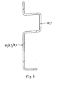
- fig. 6 shows a cross-section of an edge plate profile for the balcony of fig. 4 .
- the balcony frame of figs. 1-3 comprises a rear plate 1 parallel to the wall, side plates 2 perpendicular to the wall at the ends of the rear plate, and a front plate 3 parallel to the wall and connecting the outer ends of the side plates.
- the rear plate and the front plate are connected at a top edge with a sufficient number of upper beams 5 and at a bottom edge with a sufficient number of lower beams 6.
- the side plates and the upper beams are connected at a top edge with a sufficient number of cross beams 7.
- the rear plate 1 defines apertures 8 near its ends and, above the apertures, rear plate flanges 9 slightly wider than the apertures and extending higher than the rear plate.
- load-bearing girders 10 These have a tubular body 11, an attachment flange 12 fixed to its top surface and mountable to the rear plate flange with bolts, and at its rear end a wall flange 13 mountable to the wall with bolts.
- the frame When using short load-bearing girders such as those in fig. 1 , the frame has its outer corners further fitted with attachment brackets for tension rods by which the balcony is also suspended on the wall. If the wall is provided with long load-bearing girders capable of supporting the balcony without tension rods, the attachment beams will be omitted and the balcony will be installed by the rear plate apertures to rest on the load-bearing girders.
- the rear plate 1 and the side plates 2 consist of press-brake bent profile sheet with a thickness of 5-6 mm. It includes both an inward upper face 13 at the top edge and a similar type of lower face 14 at the bottom edge. Slightly below the midpoint is a wide U-shaped inward protrusion 15 lengthwise of the profile.
- the protrusion has its top surface slightly inclined inward for promoting the flow of water.
- the protrusion's bottom is vertical and its bottom edge is most preferably sharp for easy water droplet release.
- the protrusion's bottom surface is slightly inward sloping.
- the front plate 3 has at its top edge an inward upper face 16 and at its bottom edge an internal rain gutter 17 with a hole at least at one of its ends for the outflow of water.
- the frame is most preferably constructed from zinc-plated steel.
- the protrusion 15 included in a profile of the side plates 2 has a drain panel 18 mounted on its lower surface.
- the drain panel is fastened preferably with screws, such that the screw points will be concealed inside the protrusion.
- Between the drain panel and the protrusion's lower surface can further be a water seal, for example a sealing tape.
- the drain panel material is hot-dip galvanized sheet metal with its grooves lengthwise of the balcony.
- the drain panel is inclined sufficiently (1:100 - 1:80) towards the front plate for enabling water to flow along the panel into the front plate's rain gutter 17.
- On the frame edges are mounted railings and other possibly necessary fixtures.
- a terrace board flooring 19 Underneath the drain panel is a fireproof insulation sheet 20 (fireproof rockwool 30 mm), resting on the profile's lower face 14 and the bottom surface flooring.
- a baseboard 21 To a bottom surface of the lower face is secured a baseboard 21, which is made for example of calcium silicate.
- edge plate frame of figs. 1-3 can be used in a balcony also in an upside-down position for enabling the installation of a different type of flooring.
- both a rear plate 1.1, side plates 2.1 and a front plate 3.1 are made of metal profile sheet. Slightly above the middle part, it has an inward protrusion 15.1, which is lengthwise of the profile sheet and has a U-shaped cross-section. The protrusion's top surface and bottom surface are outward inclined and its bottom is vertical. The bottom edge has an inward lower face 14.1.
- the rear plate 1.1 and the front plate 3.1 are interconnected with two beams 5.1. These have a top edge flush with a top surface of the profile sheet's protrusion 15.1.
- the rear plate 1.1 defines apertures 22 in register with the beams.
- the beam 5.1 has two vertical legs 23 and two iron flat bars 24 connecting the same and provided with a threaded hole 25.
- the invention is intended for use in projects involving wall-mounted load bearing girders upon which the balcony is rested.
- the load-bearing girders place themselves between the legs of the balcony beams underneath the iron flat bars.
- Into the holes of the iron flat bars are inserted screws, by means of which the balcony's height with respect to the load-bearing girders can be adjusted exactly as desired regardless of height differences.
- the balcony frame is installed in a precisely horizontal position.
- the inward bent U-shaped protrusions present in the profile sheets are horizontal or inclined in a longitudinal direction.
- a concrete slab 19.2 is dimensioned so as to leave a small gap between its front edge and the edge of the profile sheet.
- the front plate protrusion 15.1 has its upper face provided with holes for allowing the outflow of water. If desired, inside the protrusion can be further fitted a rain gutter for removing water in a controlled manner for example from the gutter's end.
- the frame can have a fastener for securing a balcony to the frame.
- the edge plate frame of figs. 4 and 5 is also applicable in the embodiment of figs. 1-3 .
- each version includes a steel frame supporting both the fireproofing sheet and the board system therebelow.
Description
- The invention relates to a steel frame balcony. The invention is particularly useful in renovation, but also in new construction.
- It is prior known to manufacture and attach steel frame balconies by constructing a balcony with an attachment flange at its rear edge in register with the frame and with brackets at the corners of its front edge for fastening a tension rod. The balcony frame includes a G-shaped edge profile with a flat external side. The balcony is secured to a wall with the attachment flanges and the tension rods, followed by placing a wooden grid on top of the frame. One example of such balcony is the Producta balcony from LO Rakenne Oy.
- In
DE utility model 29920081 is disclosed a balcony which has a rectangular frame comprising a rear plate to be set against a wall, two side plates and a front plate, in which balcony at least two of the plates have between top and bottom edges a chute-like inward protrusion, and these plates are opposite to each other, which balcony is installed to rest on wall-mounted load bearing girders and which balcony has elements for adjusting the balcony's height. - In document
EP 2261430 is disclosed a balcony which has a rectangular frame comprising a rear plate to be set against a wall, two side plates and a front plate, which balcony is installed to rest on wall-mounted load bearing girders and which balcony has elements for adjusting the balcony's height. - Document
DE 299 20 081 U1 discloses the preamble of claim 1. - There is now provided an invention as presented in the claims.
- This invention relates to a balcony according to claim 1.
- According to a first feature of the invention, at least two of the plates have a chute-like inward protrusion between top and bottom edges. These two plates are those on opposite sides. Other plates may also have a similar protrusion. The chute bottom is most preferably vertical.
- In one embodiment, a top surface of the protrusion in the plates is preferably inward sloping or a bottom surface of the protrusion is straight or inward sloping. The sloping top surface can be used for directing water. To the protrusion below the top surface, preferably to the bottom surface, can be fixed a waterproofing board. Water runs from the top surface onto this board, along which it can be directed for example into and out of a rain gutter present at the edge. The waterproofing board material can be for example corrugated sheet metal. In a second embodiment, the protrusion's top surface is straight or outward sloping and the bottom surface is outward sloping. In this case, water can be directed away from an outer edge of the top protrusion surface. For this purpose, inside the protrusion can be constructed a rain gutter, into which water is directed from an edge of the plate above the protrusion. The second embodiment can also be implemented by turning upside down the frame assembly composed of the edge plates.
- The balcony has a frame edge plate with a chute-like inward protrusion between top and bottom edges.
- There is a frame assembly composed of edge plates, which can be used in a balcony with either side up.
- At a top edge of the plate can be an upper face, preferably inward from the edge. To be supported by such a top edge can be preferably installed a floor, for example a board floor. Alternatively, the plate can have a straight top edge. In this case, to be supported by the protrusion can be installed a floor, for example a tile floor. The various options can also be implemented with one and the same frame composed of edge plates, which has been constructed for a capability of being used with either side up.
- The rear plate define apertures by which the balcony is suspended on brackets mountable on the wall. If necessary, a further bracing of the balcony to the wall can be provided with tension rods. The rear plate have a fastener, an attachment flange, by which the balcony is secured to the bracket or the wall. The fastener lies above the floor level, whereby the balcony can be made completely ready for service prior to being lifted to its position.
- The balcony has a balcony fastener, which is in attachment with the balcony above the floor level.
- The balcony is also provided with elements for adjusting the balcony's height with respect to load-bearing girders. The balcony features a lengthwise beam, which is provided alongside the load-bearing girder with side legs connected above the load-bearing girder with an iron flat bar, most preferably with two of those. The iron flat bar defines a threaded hole. A screw fitted therein enables a height adjustment. As a result, variations in the height differences of load-bearing girders can be cancelled out.
- The attached drawings make up a part of a written specification for the invention and relate to the subsequently presented detailed description for a few embodiments of the invention. In the drawings,
fig. 1 shows one balcony frame in a horizontal view,fig. 2 shows a balcony with the frame offig. 1 in a cross-section parallel to the wall,fig. 3 shows a balcony with the frame offig. 1 in a cross-section perpendicular to the wall,fig. 4 is a plan view of a balcony with another type of frame,fig. 5 shows a cross-section offig. 4 parallel to the wall, andfig. 6 shows a cross-section of an edge plate profile for the balcony offig. 4 . - The balcony frame of
figs. 1-3 comprises a rear plate 1 parallel to the wall, side plates 2 perpendicular to the wall at the ends of the rear plate, and afront plate 3 parallel to the wall and connecting the outer ends of the side plates. The rear plate and the front plate are connected at a top edge with a sufficient number ofupper beams 5 and at a bottom edge with a sufficient number of lower beams 6. The side plates and the upper beams are connected at a top edge with a sufficient number of cross beams 7. - The rear plate 1 defines apertures 8 near its ends and, above the apertures,
rear plate flanges 9 slightly wider than the apertures and extending higher than the rear plate. Into the apertures are installed load-bearinggirders 10. These have atubular body 11, anattachment flange 12 fixed to its top surface and mountable to the rear plate flange with bolts, and at its rear end awall flange 13 mountable to the wall with bolts. When using short load-bearing girders such as those infig. 1 , the frame has its outer corners further fitted with attachment brackets for tension rods by which the balcony is also suspended on the wall. If the wall is provided with long load-bearing girders capable of supporting the balcony without tension rods, the attachment beams will be omitted and the balcony will be installed by the rear plate apertures to rest on the load-bearing girders. - The rear plate 1 and the side plates 2 consist of press-brake bent profile sheet with a thickness of 5-6 mm. It includes both an inward
upper face 13 at the top edge and a similar type oflower face 14 at the bottom edge. Slightly below the midpoint is a wide U-shapedinward protrusion 15 lengthwise of the profile. The protrusion has its top surface slightly inclined inward for promoting the flow of water. The protrusion's bottom is vertical and its bottom edge is most preferably sharp for easy water droplet release. The protrusion's bottom surface is slightly inward sloping. Thefront plate 3 has at its top edge an inward upper face 16 and at its bottom edge aninternal rain gutter 17 with a hole at least at one of its ends for the outflow of water. - The frame is most preferably constructed from zinc-plated steel.
- In the embodiment of
figs. 2 and 3 , theprotrusion 15 included in a profile of the side plates 2 has adrain panel 18 mounted on its lower surface. The drain panel is fastened preferably with screws, such that the screw points will be concealed inside the protrusion. Between the drain panel and the protrusion's lower surface can further be a water seal, for example a sealing tape. The drain panel material is hot-dip galvanized sheet metal with its grooves lengthwise of the balcony. The drain panel is inclined sufficiently (1:100 - 1:80) towards the front plate for enabling water to flow along the panel into the front plate'srain gutter 17. On the frame edges are mounted railings and other possibly necessary fixtures. - In the embodiment of
figs. 2 and 3 , to be supported by the plates' upper faces 13 and 16 and by thetop beams 5 and the crosswise beams 7 is installed aterrace board flooring 19. Underneath the drain panel is a fireproof insulation sheet 20 (fireproof rockwool 30 mm), resting on the profile'slower face 14 and the bottom surface flooring. To a bottom surface of the lower face is secured abaseboard 21, which is made for example of calcium silicate. - In principle, the edge plate frame of
figs. 1-3 can be used in a balcony also in an upside-down position for enabling the installation of a different type of flooring. - In the frame of
figs. 4 and 5 , both a rear plate 1.1, side plates 2.1 and a front plate 3.1 are made of metal profile sheet. Slightly above the middle part, it has an inward protrusion 15.1, which is lengthwise of the profile sheet and has a U-shaped cross-section. The protrusion's top surface and bottom surface are outward inclined and its bottom is vertical. The bottom edge has an inward lower face 14.1. - The rear plate 1.1 and the front plate 3.1 are interconnected with two beams 5.1. These have a top edge flush with a top surface of the profile sheet's protrusion 15.1. The rear plate 1.1 defines
apertures 22 in register with the beams. The beam 5.1 has twovertical legs 23 and two iron flat bars 24 connecting the same and provided with a threadedhole 25. The invention is intended for use in projects involving wall-mounted load bearing girders upon which the balcony is rested. The load-bearing girders place themselves between the legs of the balcony beams underneath the iron flat bars. Into the holes of the iron flat bars are inserted screws, by means of which the balcony's height with respect to the load-bearing girders can be adjusted exactly as desired regardless of height differences. The balcony frame is installed in a precisely horizontal position. The inward bent U-shaped protrusions present in the profile sheets are horizontal or inclined in a longitudinal direction. - To be supported by the top surface of the profile sheet protrusion 15.1 is placed a concrete slab 19.2. The slab is dimensioned so as to leave a small gap between its front edge and the edge of the profile sheet. The front plate protrusion 15.1 has its upper face provided with holes for allowing the outflow of water. If desired, inside the protrusion can be further fitted a rain gutter for removing water in a controlled manner for example from the gutter's end.
- Above its floor level, the frame can have a fastener for securing a balcony to the frame.
- The edge plate frame of
figs. 4 and 5 is also applicable in the embodiment offigs. 1-3 . - The bottom surface of each version includes a steel frame supporting both the fireproofing sheet and the board system therebelow.
Claims (7)
- A balcony, which has a rectangular frame comprising a rear plate (1; 1.1) to be set against a wall, two side plates (2; 2.1), and a front plate (3; 3.1), in which at least two of the plates have between top and bottom edges a chute-like inward protrusion (15; 15.1), and these plates are opposite to each other, which the balcony is installed to rest on wall-mounted load bearing girders, and the balcony has elements (5.1, 24, 25) for adjusting the balcony's height with respect to the load-bearing girders, and the rear plate (1) has apertures (8), characterized in that the rear plate flanges (9) are extending above the rear plate, the apertures (8) having fitted therein load-bearing girders (10) which have a tubular body (11), to the top surface of which is fixed an attachment flange (12) capable of being fastened to the rear plate flange.
- A balcony as set forth in claim 1, wherein a top surface of the protrusion (15) is inward sloping or a bottom surface of the protrusion (15) is inward sloping or horizontal.
- A balcony as set forth in claim 1 or 2, wherein to the protrusion (15), below the top surface, is attached a waterproofing insulation board (18) inside the balcony.
- A balcony as set forth in any of the preceding claims, wherein the plate (1; 2; 3) has at its top edge an upper face (13) or the top edge of the plate (1.1; 2.1; 3.1) is straight.
- A balcony as set forth in claim 4, wherein the plate (1; 2; 3) has at its top edge an upper face (13) and to be supported thereby is installed a floor (19) or the top edge of the plate (1.1; 2.1; 3.1) is straight and to be supported by the protrusion (15.1) is installed a floor (19.1).
- A balcony as set forth in claim 5, wherein the plate (1; 2; 3) has at its top edge an upper face (13) and to be supported thereby is installed a board floor (19) or the top edge of the plate (1.1; 2.1; 3.1) is straight and to be supported by the protrusion (15.1) is installed a tile floor (19.1).
- A balcony as set forth in any of the preceding claims, wherein the frame is capable of being used also in an upside-down position in the balcony.
Applications Claiming Priority (1)
| Application Number | Priority Date | Filing Date | Title |
|---|---|---|---|
| FI20125534A FI125877B (en) | 2012-05-21 | 2012-05-21 | BALCONY |
Publications (3)
| Publication Number | Publication Date |
|---|---|
| EP2666918A2 EP2666918A2 (en) | 2013-11-27 |
| EP2666918A3 EP2666918A3 (en) | 2014-06-25 |
| EP2666918B1 true EP2666918B1 (en) | 2015-07-22 |
Family
ID=48446155
Family Applications (1)
| Application Number | Title | Priority Date | Filing Date |
|---|---|---|---|
| EP13168166.0A Not-in-force EP2666918B1 (en) | 2012-05-21 | 2013-05-17 | Balcony |
Country Status (2)
| Country | Link |
|---|---|
| EP (1) | EP2666918B1 (en) |
| FI (1) | FI125877B (en) |
Families Citing this family (1)
| Publication number | Priority date | Publication date | Assignee | Title |
|---|---|---|---|---|
| GB2558272A (en) * | 2016-12-23 | 2018-07-11 | Brooksby Projects Ltd | Balcony structures |
Family Cites Families (3)
| Publication number | Priority date | Publication date | Assignee | Title |
|---|---|---|---|---|
| DE29920081U1 (en) * | 1999-11-16 | 2000-01-13 | Giller Jutta | Metal balcony |
| FI123579B (en) * | 2009-06-10 | 2013-07-31 | Lo Rakenne Oy | Procedure for forming a concrete projection and concrete slab |
| FR2954370B1 (en) * | 2009-12-23 | 2018-09-07 | Bugal | PLATFORM SUCH AS BALCONY OR TERRACE |
-
2012
- 2012-05-21 FI FI20125534A patent/FI125877B/en active IP Right Grant
-
2013
- 2013-05-17 EP EP13168166.0A patent/EP2666918B1/en not_active Not-in-force
Also Published As
| Publication number | Publication date |
|---|---|
| EP2666918A3 (en) | 2014-06-25 |
| FI125877B (en) | 2016-03-31 |
| EP2666918A2 (en) | 2013-11-27 |
| FI20125534A (en) | 2013-11-22 |
Similar Documents
| Publication | Publication Date | Title |
|---|---|---|
| KR200452381Y1 (en) | Device for Fixing a Exterior Materials of Building | |
| RU2011143756A (en) | FUNCTIONAL SYSTEM FOR PANEL FROM CEMENT MORTAR WITH PRELIMINARY TENSIONED TWO-AXLE FITTINGS | |
| US20130291465A1 (en) | Vented wall girts | |
| US20170101784A1 (en) | Locking and regulation device for panels and slabs | |
| FI124196B (en) | System for a roof construction and a roofing piece | |
| CA2958631C (en) | Peripheral stabilizing system for elevated flooring surface | |
| RU2052039C1 (en) | Roofing panel for slope roofs | |
| JP4998446B2 (en) | Underfloor ventilation structure | |
| EP2666918B1 (en) | Balcony | |
| JP5415241B2 (en) | Support hardware | |
| SK8724Y1 (en) | A cladding building system | |
| US20060179745A1 (en) | Method of building a building | |
| EP2182140B1 (en) | Kit for a sanitary cell and corresponding sanitary cell | |
| US1786751A (en) | Roof construction | |
| RU102646U1 (en) | WALL HEAT-INSULATING PANEL WITH VENTILATED FACADE OF FACTORY READINESS "ROSLAV" AND SUPPORT BRACKET FOR ITS INSTALLATION | |
| RU2143041C1 (en) | Metal panel for ventilated facades "triol" | |
| CA2847473C (en) | Modular system for continuously insulating exterior walls of a structure and securing exterior cladding to the structure | |
| CN219824782U (en) | Assembled pavement slab mounting structure | |
| RU2649199C1 (en) | Wall cladding system | |
| US20210071427A1 (en) | Building rail system | |
| WO2020003496A1 (en) | Waterproofing structure | |
| JP3764078B2 (en) | Mounting structure and mounting method of overhang structure | |
| JP2022116734A (en) | roof structure | |
| CZ11772U1 (en) | Balcony | |
| EP1222341B1 (en) | Device at a building made by sheet metal |
Legal Events
| Date | Code | Title | Description |
|---|---|---|---|
| PUAI | Public reference made under article 153(3) epc to a published international application that has entered the european phase |
Free format text: ORIGINAL CODE: 0009012 |
|
| AK | Designated contracting states |
Kind code of ref document: A2 Designated state(s): AL AT BE BG CH CY CZ DE DK EE ES FI FR GB GR HR HU IE IS IT LI LT LU LV MC MK MT NL NO PL PT RO RS SE SI SK SM TR |
|
| AX | Request for extension of the european patent |
Extension state: BA ME |
|
| PUAL | Search report despatched |
Free format text: ORIGINAL CODE: 0009013 |
|
| AK | Designated contracting states |
Kind code of ref document: A3 Designated state(s): AL AT BE BG CH CY CZ DE DK EE ES FI FR GB GR HR HU IE IS IT LI LT LU LV MC MK MT NL NO PL PT RO RS SE SI SK SM TR |
|
| AX | Request for extension of the european patent |
Extension state: BA ME |
|
| RIC1 | Information provided on ipc code assigned before grant |
Ipc: E04B 1/00 20060101AFI20140520BHEP |
|
| 17P | Request for examination filed |
Effective date: 20141211 |
|
| RBV | Designated contracting states (corrected) |
Designated state(s): AL AT BE BG CH CY CZ DE DK EE ES FI FR GB GR HR HU IE IS IT LI LT LU LV MC MK MT NL NO PL PT RO RS SE SI SK SM TR |
|
| GRAP | Despatch of communication of intention to grant a patent |
Free format text: ORIGINAL CODE: EPIDOSNIGR1 |
|
| INTG | Intention to grant announced |
Effective date: 20150420 |
|
| GRAS | Grant fee paid |
Free format text: ORIGINAL CODE: EPIDOSNIGR3 |
|
| GRAA | (expected) grant |
Free format text: ORIGINAL CODE: 0009210 |
|
| AK | Designated contracting states |
Kind code of ref document: B1 Designated state(s): AL AT BE BG CH CY CZ DE DK EE ES FI FR GB GR HR HU IE IS IT LI LT LU LV MC MK MT NL NO PL PT RO RS SE SI SK SM TR |
|
| REG | Reference to a national code |
Ref country code: GB Ref legal event code: FG4D |
|
| REG | Reference to a national code |
Ref country code: CH Ref legal event code: EP |
|
| REG | Reference to a national code |
Ref country code: IE Ref legal event code: FG4D |
|
| REG | Reference to a national code |
Ref country code: AT Ref legal event code: REF Ref document number: 738021 Country of ref document: AT Kind code of ref document: T Effective date: 20150815 |
|
| REG | Reference to a national code |
Ref country code: DE Ref legal event code: R096 Ref document number: 602013002340 Country of ref document: DE |
|
| REG | Reference to a national code |
Ref country code: AT Ref legal event code: MK05 Ref document number: 738021 Country of ref document: AT Kind code of ref document: T Effective date: 20150722 |
|
| REG | Reference to a national code |
Ref country code: LT Ref legal event code: MG4D |
|
| REG | Reference to a national code |
Ref country code: NL Ref legal event code: MP Effective date: 20150722 |
|
| PG25 | Lapsed in a contracting state [announced via postgrant information from national office to epo] |
Ref country code: LV Free format text: LAPSE BECAUSE OF FAILURE TO SUBMIT A TRANSLATION OF THE DESCRIPTION OR TO PAY THE FEE WITHIN THE PRESCRIBED TIME-LIMIT Effective date: 20150722 Ref country code: FI Free format text: LAPSE BECAUSE OF FAILURE TO SUBMIT A TRANSLATION OF THE DESCRIPTION OR TO PAY THE FEE WITHIN THE PRESCRIBED TIME-LIMIT Effective date: 20150722 Ref country code: GR Free format text: LAPSE BECAUSE OF FAILURE TO SUBMIT A TRANSLATION OF THE DESCRIPTION OR TO PAY THE FEE WITHIN THE PRESCRIBED TIME-LIMIT Effective date: 20151023 Ref country code: LT Free format text: LAPSE BECAUSE OF FAILURE TO SUBMIT A TRANSLATION OF THE DESCRIPTION OR TO PAY THE FEE WITHIN THE PRESCRIBED TIME-LIMIT Effective date: 20150722 Ref country code: NO Free format text: LAPSE BECAUSE OF FAILURE TO SUBMIT A TRANSLATION OF THE DESCRIPTION OR TO PAY THE FEE WITHIN THE PRESCRIBED TIME-LIMIT Effective date: 20151022 |
|
| PG25 | Lapsed in a contracting state [announced via postgrant information from national office to epo] |
Ref country code: RS Free format text: LAPSE BECAUSE OF FAILURE TO SUBMIT A TRANSLATION OF THE DESCRIPTION OR TO PAY THE FEE WITHIN THE PRESCRIBED TIME-LIMIT Effective date: 20150722 Ref country code: AT Free format text: LAPSE BECAUSE OF FAILURE TO SUBMIT A TRANSLATION OF THE DESCRIPTION OR TO PAY THE FEE WITHIN THE PRESCRIBED TIME-LIMIT Effective date: 20150722 Ref country code: SE Free format text: LAPSE BECAUSE OF FAILURE TO SUBMIT A TRANSLATION OF THE DESCRIPTION OR TO PAY THE FEE WITHIN THE PRESCRIBED TIME-LIMIT Effective date: 20150722 Ref country code: HR Free format text: LAPSE BECAUSE OF FAILURE TO SUBMIT A TRANSLATION OF THE DESCRIPTION OR TO PAY THE FEE WITHIN THE PRESCRIBED TIME-LIMIT Effective date: 20150722 Ref country code: IS Free format text: LAPSE BECAUSE OF FAILURE TO SUBMIT A TRANSLATION OF THE DESCRIPTION OR TO PAY THE FEE WITHIN THE PRESCRIBED TIME-LIMIT Effective date: 20151122 Ref country code: PT Free format text: LAPSE BECAUSE OF FAILURE TO SUBMIT A TRANSLATION OF THE DESCRIPTION OR TO PAY THE FEE WITHIN THE PRESCRIBED TIME-LIMIT Effective date: 20151123 Ref country code: ES Free format text: LAPSE BECAUSE OF FAILURE TO SUBMIT A TRANSLATION OF THE DESCRIPTION OR TO PAY THE FEE WITHIN THE PRESCRIBED TIME-LIMIT Effective date: 20150722 Ref country code: PL Free format text: LAPSE BECAUSE OF FAILURE TO SUBMIT A TRANSLATION OF THE DESCRIPTION OR TO PAY THE FEE WITHIN THE PRESCRIBED TIME-LIMIT Effective date: 20150722 |
|
| REG | Reference to a national code |
Ref country code: DE Ref legal event code: R097 Ref document number: 602013002340 Country of ref document: DE |
|
| PG25 | Lapsed in a contracting state [announced via postgrant information from national office to epo] |
Ref country code: SK Free format text: LAPSE BECAUSE OF FAILURE TO SUBMIT A TRANSLATION OF THE DESCRIPTION OR TO PAY THE FEE WITHIN THE PRESCRIBED TIME-LIMIT Effective date: 20150722 Ref country code: CZ Free format text: LAPSE BECAUSE OF FAILURE TO SUBMIT A TRANSLATION OF THE DESCRIPTION OR TO PAY THE FEE WITHIN THE PRESCRIBED TIME-LIMIT Effective date: 20150722 Ref country code: IT Free format text: LAPSE BECAUSE OF FAILURE TO SUBMIT A TRANSLATION OF THE DESCRIPTION OR TO PAY THE FEE WITHIN THE PRESCRIBED TIME-LIMIT Effective date: 20150722 Ref country code: EE Free format text: LAPSE BECAUSE OF FAILURE TO SUBMIT A TRANSLATION OF THE DESCRIPTION OR TO PAY THE FEE WITHIN THE PRESCRIBED TIME-LIMIT Effective date: 20150722 Ref country code: DK Free format text: LAPSE BECAUSE OF FAILURE TO SUBMIT A TRANSLATION OF THE DESCRIPTION OR TO PAY THE FEE WITHIN THE PRESCRIBED TIME-LIMIT Effective date: 20150722 |
|
| PLBE | No opposition filed within time limit |
Free format text: ORIGINAL CODE: 0009261 |
|
| STAA | Information on the status of an ep patent application or granted ep patent |
Free format text: STATUS: NO OPPOSITION FILED WITHIN TIME LIMIT |
|
| PG25 | Lapsed in a contracting state [announced via postgrant information from national office to epo] |
Ref country code: RO Free format text: LAPSE BECAUSE OF FAILURE TO SUBMIT A TRANSLATION OF THE DESCRIPTION OR TO PAY THE FEE WITHIN THE PRESCRIBED TIME-LIMIT Effective date: 20150722 |
|
| 26N | No opposition filed |
Effective date: 20160425 |
|
| PG25 | Lapsed in a contracting state [announced via postgrant information from national office to epo] |
Ref country code: BE Free format text: LAPSE BECAUSE OF NON-PAYMENT OF DUE FEES Effective date: 20160531 Ref country code: SI Free format text: LAPSE BECAUSE OF FAILURE TO SUBMIT A TRANSLATION OF THE DESCRIPTION OR TO PAY THE FEE WITHIN THE PRESCRIBED TIME-LIMIT Effective date: 20150722 |
|
| PG25 | Lapsed in a contracting state [announced via postgrant information from national office to epo] |
Ref country code: LU Free format text: LAPSE BECAUSE OF FAILURE TO SUBMIT A TRANSLATION OF THE DESCRIPTION OR TO PAY THE FEE WITHIN THE PRESCRIBED TIME-LIMIT Effective date: 20160517 Ref country code: BE Free format text: LAPSE BECAUSE OF FAILURE TO SUBMIT A TRANSLATION OF THE DESCRIPTION OR TO PAY THE FEE WITHIN THE PRESCRIBED TIME-LIMIT Effective date: 20150722 |
|
| REG | Reference to a national code |
Ref country code: CH Ref legal event code: PL |
|
| PG25 | Lapsed in a contracting state [announced via postgrant information from national office to epo] |
Ref country code: CH Free format text: LAPSE BECAUSE OF NON-PAYMENT OF DUE FEES Effective date: 20160531 Ref country code: LI Free format text: LAPSE BECAUSE OF NON-PAYMENT OF DUE FEES Effective date: 20160531 |
|
| REG | Reference to a national code |
Ref country code: IE Ref legal event code: MM4A |
|
| REG | Reference to a national code |
Ref country code: FR Ref legal event code: ST Effective date: 20170131 |
|
| PG25 | Lapsed in a contracting state [announced via postgrant information from national office to epo] |
Ref country code: FR Free format text: LAPSE BECAUSE OF NON-PAYMENT OF DUE FEES Effective date: 20160531 |
|
| PG25 | Lapsed in a contracting state [announced via postgrant information from national office to epo] |
Ref country code: IE Free format text: LAPSE BECAUSE OF NON-PAYMENT OF DUE FEES Effective date: 20160517 |
|
| PG25 | Lapsed in a contracting state [announced via postgrant information from national office to epo] |
Ref country code: NL Free format text: LAPSE BECAUSE OF FAILURE TO SUBMIT A TRANSLATION OF THE DESCRIPTION OR TO PAY THE FEE WITHIN THE PRESCRIBED TIME-LIMIT Effective date: 20150722 |
|
| GBPC | Gb: european patent ceased through non-payment of renewal fee |
Effective date: 20170517 |
|
| PG25 | Lapsed in a contracting state [announced via postgrant information from national office to epo] |
Ref country code: GB Free format text: LAPSE BECAUSE OF NON-PAYMENT OF DUE FEES Effective date: 20170517 |
|
| PG25 | Lapsed in a contracting state [announced via postgrant information from national office to epo] |
Ref country code: CY Free format text: LAPSE BECAUSE OF FAILURE TO SUBMIT A TRANSLATION OF THE DESCRIPTION OR TO PAY THE FEE WITHIN THE PRESCRIBED TIME-LIMIT Effective date: 20150722 Ref country code: SM Free format text: LAPSE BECAUSE OF FAILURE TO SUBMIT A TRANSLATION OF THE DESCRIPTION OR TO PAY THE FEE WITHIN THE PRESCRIBED TIME-LIMIT Effective date: 20150722 Ref country code: HU Free format text: LAPSE BECAUSE OF FAILURE TO SUBMIT A TRANSLATION OF THE DESCRIPTION OR TO PAY THE FEE WITHIN THE PRESCRIBED TIME-LIMIT; INVALID AB INITIO Effective date: 20130517 |
|
| PG25 | Lapsed in a contracting state [announced via postgrant information from national office to epo] |
Ref country code: MK Free format text: LAPSE BECAUSE OF FAILURE TO SUBMIT A TRANSLATION OF THE DESCRIPTION OR TO PAY THE FEE WITHIN THE PRESCRIBED TIME-LIMIT Effective date: 20150722 Ref country code: MC Free format text: LAPSE BECAUSE OF FAILURE TO SUBMIT A TRANSLATION OF THE DESCRIPTION OR TO PAY THE FEE WITHIN THE PRESCRIBED TIME-LIMIT Effective date: 20150722 Ref country code: TR Free format text: LAPSE BECAUSE OF FAILURE TO SUBMIT A TRANSLATION OF THE DESCRIPTION OR TO PAY THE FEE WITHIN THE PRESCRIBED TIME-LIMIT Effective date: 20150722 Ref country code: MT Free format text: LAPSE BECAUSE OF NON-PAYMENT OF DUE FEES Effective date: 20160531 |
|
| PG25 | Lapsed in a contracting state [announced via postgrant information from national office to epo] |
Ref country code: BG Free format text: LAPSE BECAUSE OF FAILURE TO SUBMIT A TRANSLATION OF THE DESCRIPTION OR TO PAY THE FEE WITHIN THE PRESCRIBED TIME-LIMIT Effective date: 20150722 |
|
| PGFP | Annual fee paid to national office [announced via postgrant information from national office to epo] |
Ref country code: DE Payment date: 20180518 Year of fee payment: 6 |
|
| PG25 | Lapsed in a contracting state [announced via postgrant information from national office to epo] |
Ref country code: AL Free format text: LAPSE BECAUSE OF FAILURE TO SUBMIT A TRANSLATION OF THE DESCRIPTION OR TO PAY THE FEE WITHIN THE PRESCRIBED TIME-LIMIT Effective date: 20150722 |
|
| REG | Reference to a national code |
Ref country code: DE Ref legal event code: R119 Ref document number: 602013002340 Country of ref document: DE |
|
| PG25 | Lapsed in a contracting state [announced via postgrant information from national office to epo] |
Ref country code: DE Free format text: LAPSE BECAUSE OF NON-PAYMENT OF DUE FEES Effective date: 20191203 |