EP2666698A2 - Lenkstange für Wagenrolle - Google Patents
Lenkstange für Wagenrolle Download PDFInfo
- Publication number
- EP2666698A2 EP2666698A2 EP13167777.5A EP13167777A EP2666698A2 EP 2666698 A2 EP2666698 A2 EP 2666698A2 EP 13167777 A EP13167777 A EP 13167777A EP 2666698 A2 EP2666698 A2 EP 2666698A2
- Authority
- EP
- European Patent Office
- Prior art keywords
- trolley
- drum
- reel
- handle
- winding device
- Prior art date
- Legal status (The legal status is an assumption and is not a legal conclusion. Google has not performed a legal analysis and makes no representation as to the accuracy of the status listed.)
- Withdrawn
Links
- 238000004804 winding Methods 0.000 description 18
- XLYOFNOQVPJJNP-UHFFFAOYSA-N water Substances O XLYOFNOQVPJJNP-UHFFFAOYSA-N 0.000 description 7
- 230000000284 resting effect Effects 0.000 description 3
- 239000002184 metal Substances 0.000 description 2
- 230000003247 decreasing effect Effects 0.000 description 1
- 238000006073 displacement reaction Methods 0.000 description 1
- 238000010413 gardening Methods 0.000 description 1
- 230000002262 irrigation Effects 0.000 description 1
- 238000003973 irrigation Methods 0.000 description 1
- 239000008400 supply water Substances 0.000 description 1
Images


Classifications
-
- B—PERFORMING OPERATIONS; TRANSPORTING
- B62—LAND VEHICLES FOR TRAVELLING OTHERWISE THAN ON RAILS
- B62B—HAND-PROPELLED VEHICLES, e.g. HAND CARTS OR PERAMBULATORS; SLEDGES
- B62B1/00—Hand carts having only one axis carrying one or more transport wheels; Equipment therefor
- B62B1/10—Hand carts having only one axis carrying one or more transport wheels; Equipment therefor in which the load is intended to be transferred totally to the wheels
- B62B1/12—Hand carts having only one axis carrying one or more transport wheels; Equipment therefor in which the load is intended to be transferred totally to the wheels involving parts being adjustable, collapsible, attachable, detachable, or convertible
- B62B1/125—Hand carts having only one axis carrying one or more transport wheels; Equipment therefor in which the load is intended to be transferred totally to the wheels involving parts being adjustable, collapsible, attachable, detachable, or convertible by means of telescoping elements
-
- B—PERFORMING OPERATIONS; TRANSPORTING
- B62—LAND VEHICLES FOR TRAVELLING OTHERWISE THAN ON RAILS
- B62B—HAND-PROPELLED VEHICLES, e.g. HAND CARTS OR PERAMBULATORS; SLEDGES
- B62B1/00—Hand carts having only one axis carrying one or more transport wheels; Equipment therefor
- B62B1/26—Hand carts having only one axis carrying one or more transport wheels; Equipment therefor characterised by supports specially adapted to objects of definite shape
-
- B—PERFORMING OPERATIONS; TRANSPORTING
- B62—LAND VEHICLES FOR TRAVELLING OTHERWISE THAN ON RAILS
- B62B—HAND-PROPELLED VEHICLES, e.g. HAND CARTS OR PERAMBULATORS; SLEDGES
- B62B3/00—Hand carts having more than one axis carrying transport wheels; Steering devices therefor; Equipment therefor
- B62B3/02—Hand carts having more than one axis carrying transport wheels; Steering devices therefor; Equipment therefor involving parts being adjustable, collapsible, attachable, detachable or convertible
-
- B—PERFORMING OPERATIONS; TRANSPORTING
- B62—LAND VEHICLES FOR TRAVELLING OTHERWISE THAN ON RAILS
- B62B—HAND-PROPELLED VEHICLES, e.g. HAND CARTS OR PERAMBULATORS; SLEDGES
- B62B5/00—Accessories or details specially adapted for hand carts
- B62B5/06—Hand moving equipment, e.g. handle bars
- B62B5/064—Hand moving equipment, e.g. handle bars adaptable for different users, e.g. by means of pivoting elements
- B62B5/065—Hand moving equipment, e.g. handle bars adaptable for different users, e.g. by means of pivoting elements by means of telescopic elements
-
- B—PERFORMING OPERATIONS; TRANSPORTING
- B65—CONVEYING; PACKING; STORING; HANDLING THIN OR FILAMENTARY MATERIAL
- B65H—HANDLING THIN OR FILAMENTARY MATERIAL, e.g. SHEETS, WEBS, CABLES
- B65H75/00—Storing webs, tapes, or filamentary material, e.g. on reels
- B65H75/02—Cores, formers, supports, or holders for coiled, wound, or folded material, e.g. reels, spindles, bobbins, cop tubes, cans, mandrels or chucks
- B65H75/34—Cores, formers, supports, or holders for coiled, wound, or folded material, e.g. reels, spindles, bobbins, cop tubes, cans, mandrels or chucks specially adapted or mounted for storing and repeatedly paying-out and re-storing lengths of material provided for particular purposes, e.g. anchored hoses, power cables
- B65H75/38—Cores, formers, supports, or holders for coiled, wound, or folded material, e.g. reels, spindles, bobbins, cop tubes, cans, mandrels or chucks specially adapted or mounted for storing and repeatedly paying-out and re-storing lengths of material provided for particular purposes, e.g. anchored hoses, power cables involving the use of a core or former internal to, and supporting, a stored package of material
- B65H75/40—Cores, formers, supports, or holders for coiled, wound, or folded material, e.g. reels, spindles, bobbins, cop tubes, cans, mandrels or chucks specially adapted or mounted for storing and repeatedly paying-out and re-storing lengths of material provided for particular purposes, e.g. anchored hoses, power cables involving the use of a core or former internal to, and supporting, a stored package of material mobile or transportable
- B65H75/403—Carriage with wheels
-
- B—PERFORMING OPERATIONS; TRANSPORTING
- B65—CONVEYING; PACKING; STORING; HANDLING THIN OR FILAMENTARY MATERIAL
- B65H—HANDLING THIN OR FILAMENTARY MATERIAL, e.g. SHEETS, WEBS, CABLES
- B65H75/00—Storing webs, tapes, or filamentary material, e.g. on reels
- B65H75/02—Cores, formers, supports, or holders for coiled, wound, or folded material, e.g. reels, spindles, bobbins, cop tubes, cans, mandrels or chucks
- B65H75/34—Cores, formers, supports, or holders for coiled, wound, or folded material, e.g. reels, spindles, bobbins, cop tubes, cans, mandrels or chucks specially adapted or mounted for storing and repeatedly paying-out and re-storing lengths of material provided for particular purposes, e.g. anchored hoses, power cables
- B65H75/38—Cores, formers, supports, or holders for coiled, wound, or folded material, e.g. reels, spindles, bobbins, cop tubes, cans, mandrels or chucks specially adapted or mounted for storing and repeatedly paying-out and re-storing lengths of material provided for particular purposes, e.g. anchored hoses, power cables involving the use of a core or former internal to, and supporting, a stored package of material
- B65H75/44—Constructional details
- B65H75/4457—Arrangements of the frame or housing
- B65H75/446—Arrangements of the frame or housing for releasably or permanently attaching the frame to a wall, on a floor or on a post or the like
-
- B—PERFORMING OPERATIONS; TRANSPORTING
- B62—LAND VEHICLES FOR TRAVELLING OTHERWISE THAN ON RAILS
- B62B—HAND-PROPELLED VEHICLES, e.g. HAND CARTS OR PERAMBULATORS; SLEDGES
- B62B2202/00—Indexing codes relating to type or characteristics of transported articles
- B62B2202/02—Cylindrically-shaped articles, e.g. drums, barrels, flasks
- B62B2202/025—Reels, e.g. for filamentary or sheet material
-
- B—PERFORMING OPERATIONS; TRANSPORTING
- B65—CONVEYING; PACKING; STORING; HANDLING THIN OR FILAMENTARY MATERIAL
- B65H—HANDLING THIN OR FILAMENTARY MATERIAL, e.g. SHEETS, WEBS, CABLES
- B65H2701/00—Handled material; Storage means
- B65H2701/30—Handled filamentary material
- B65H2701/33—Hollow or hose-like material
Definitions
- the present invention relates to a manoeuvring handle for trolley reel.
- the use of widespread, common flexible pipes is at the basis of irrigating more or less extended fields, and subsequently of water distribution.
- the flexible pipe is to cover, with the entire length thereof and the displacement thereof, the entire surface wanted to be replenished with water.
- the reel falls within this context and during movements along the work route, allows an adequate length of the flexible pipe to be available, thus at the same time ensuring an orderly repositioning once work is complete.
- Trolley reels which comprise a pipe winding device and a trolley with wheels for moving the pipe winding device.
- the pipe winding device comprises a drum for winding the flexible pipe, which is rotatably supported by a pair of trolley side walls.
- a crank allows the manual rotation of the drum to wind the flexible pipe.
- a handle for manoeuvring the trolley extends upwards from the trolley.
- the pipe winding device and the trolley typically form a single structure, but may be made separable from each other in the way described in a concurrent patent application filed by the applicant. In the latter case, the pipe winding device may be removed and rested on the ground or attached to a wall and the trolley may be temporarily intended for other uses.
- the axis of rotation of the drum is perpendicular to the advancing direction of the trolley, resulting in one of the pins with which the trolley is rotatably supported by the side walls possibly also acting as fitting, firstly, for the flexible pipe wound on the drum and, secondly, for a further flexible pipe intended to connect the reel to a water supply intake.
- a reel with drum which is rotatable about an axis parallel to the advancing direction of the trolley would allow decreasing the lateral volume of the reel, as is desirable in most cases.
- a manoeuvring handle for a trolley reel with drum rotatable about an axis parallel to the advancing direction of the trolley characterized in that it comprises a telescopic structure with fixed lower part and movable upper part which extends upwards from a rear portion of the trolley in position laterally displaced with respect to the axis of rotation of the drum.
- the fixed lower part of the aforesaid telescopic structure is placed beside a corresponding side wall for supporting the drum and may be connected at the two side ends of the rear portion of the trolley by means of appropriate connecting bars.
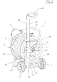
- a reel 1 for flexible irrigation pipe 2 comprises a pipe winding device 50 consisting of a flanged drum 3 rotatably supported by two arched side walls 4 with weight-reducing holes 5.
- the two side walls 4 are connected by an upper tubular element 6 with ends inserted within specific housings 7 on the upper part of the side walls 4, and by a pair of lower tubular bars 51 in turn with ends inserted within housings 52 of the side walls 4.
- crank 11 is provided for the rotation of drum 3 about the axis thereof, which is kinetically connected to the supporting shaft and rotation of the drum (which fastening ring nut 12 is shown in figure 1 ) by means of a reduction gear 10 inserted in one of the two side walls 4.
- crank 11 may be directly positioned on the axis of rotation of the drum.
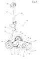
- the pipe winding device 50 is placed on a trolley 13 provided with freely rotatable resting wheels 14, and the positioning is such that the projections of the pipe winding device 50 are at positioning seats 15, 16 and at a cavity 17 located on a base 18 of trolley 13, as shown in figure 4 .
- Base 18 comprises two oval cavities 19 and a metal tubular U-shaped supporting frame 20, with ends inserted within side housings 21 of base 18.
- Frame 20 extends below base 18 thus offering a mechanical support thereto and to the pipe winding device 50 above, when present.
- the pipe winding device 50 is fastened to base 18 of trolley 13 by means of a pedal 22, as described in a concurrent Italian patent application filed by the applicant.
- the pipe winding device 50 can also be used from a fixed position, such as for example resting on the ground or attached to a wall, while trolley 13 may be used separately for the most assorted functions with other types of loads.
- the pipe winding device can be rested on the ground and fastened to the wall due to the parallel bars 51, while the pipe winding device 50 can be manually moved due to the tubular element 6.
- the pipe winding device 50 is positioned on base 18 of trolley 13 with the axis of rotation of the drum perpendicular to the one of the wheels 14 (see figure 1 ) and hence parallel to the advancing direction of trolley 13. Thereby, a trolley 13 with small lateral dimensions is obtained.
- trolley 13 provides a manoeuvring handle 26 with handgrip 53, which has a telescopic structure with fixed lower part 41 and a movable upper part 42 which can be inserted and removed vertically with respect to the fixed part 41.
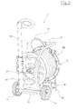
- Handle 26 is in laterally moved position with respect to the axis of rotation of reel 50 drum 3 so as to make a fitting 27 ( fig. 2 ) accessible to be used for connecting the flexible pipe 2 to a further segment of flexible pipe connected to a water supply intake.
- the fixed part 41 of handle 26 is fastened to an underlying rear portion 23 of trolley 13 and is stabilized with respect thereto by means of two tubular bars 28 and 29, which are inferiorly fastened to the two side ends of the aforesaid rear portion 23 of the trolley ( figures 2 and 4 ) and converge at the top into a junction structure 30.
- trolley 13 can advance and move back with or without pipe winding device 50 in a balanced manner, even though said handle 26 is offset.
- the two bars 28 and 29 may be excluded, and the fixed part 41 may in this case be fastened to the adjacent side wall 4, if the pipe winding device 50 is restrained to trolley 13 in a non-separable manner ( figure 3 ).
- a model of reel 1 with a trolley 13 with four freely rotatable resting wheels 14 is also provided ( figure 5 ).
- the metal tubular supporting frame 20 is not provided, because base 18 alone, which is larger in size with respect to the two-wheel example, is able of supporting the weight of the fastened load.
- the positioning seats 15, 16 are located at the four corners of the surface of base 18. The reel fastening modes remain the ones described with two-wheel trolley 13.
Landscapes
- Engineering & Computer Science (AREA)
- Chemical & Material Sciences (AREA)
- Combustion & Propulsion (AREA)
- Transportation (AREA)
- Mechanical Engineering (AREA)
- Storing, Repeated Paying-Out, And Re-Storing Of Elongated Articles (AREA)
- Carriers, Traveling Bodies, And Overhead Traveling Cranes (AREA)
Applications Claiming Priority (1)
| Application Number | Priority Date | Filing Date | Title |
|---|---|---|---|
| ITMI20120197 ITMI20120197U1 (it) | 2012-05-21 | 2012-05-21 | Manico di movimentazione per avvolgitubo a carrello. |
Publications (2)
| Publication Number | Publication Date |
|---|---|
| EP2666698A2 true EP2666698A2 (de) | 2013-11-27 |
| EP2666698A3 EP2666698A3 (de) | 2014-06-18 |
Family
ID=46833815
Family Applications (1)
| Application Number | Title | Priority Date | Filing Date |
|---|---|---|---|
| EP13167777.5A Withdrawn EP2666698A3 (de) | 2012-05-21 | 2013-05-15 | Lenkstange für Wagenrolle |
Country Status (2)
| Country | Link |
|---|---|
| EP (1) | EP2666698A3 (de) |
| IT (1) | ITMI20120197U1 (de) |
Cited By (2)
| Publication number | Priority date | Publication date | Assignee | Title |
|---|---|---|---|---|
| CN103964193A (zh) * | 2014-05-04 | 2014-08-06 | 高峰 | 一种拖物式摇架机构 |
| CN108792845A (zh) * | 2018-08-21 | 2018-11-13 | 胡江波 | 一种农业灌溉用水带快速收放装置 |
Family Cites Families (3)
| Publication number | Priority date | Publication date | Assignee | Title |
|---|---|---|---|---|
| SE7513099L (sv) * | 1974-11-22 | 1976-05-24 | S A S Claber | Vagn for lidning av flexibelt material, serskilt for lindning av ror eller slangar for besprutning av tredgardar, kokstredgardar, osv. |
| DE202008015079U1 (de) * | 2008-11-13 | 2009-02-19 | Uni-Elektra Gmbh | Kabeltrommel mit ausziehbarem Handgriff |
| DE202010013463U1 (de) * | 2010-09-23 | 2011-02-03 | J. Wagner Gmbh | Vorrichtung zur Aufnahme und Aufbewahrung eines Schlauches mit Heizsystem |
-
2012
- 2012-05-21 IT ITMI20120197 patent/ITMI20120197U1/it unknown
-
2013
- 2013-05-15 EP EP13167777.5A patent/EP2666698A3/de not_active Withdrawn
Non-Patent Citations (1)
| Title |
|---|
| None |
Cited By (3)
| Publication number | Priority date | Publication date | Assignee | Title |
|---|---|---|---|---|
| CN103964193A (zh) * | 2014-05-04 | 2014-08-06 | 高峰 | 一种拖物式摇架机构 |
| CN103964193B (zh) * | 2014-05-04 | 2016-03-30 | 谢娟 | 一种拖物式摇架机构 |
| CN108792845A (zh) * | 2018-08-21 | 2018-11-13 | 胡江波 | 一种农业灌溉用水带快速收放装置 |
Also Published As
| Publication number | Publication date |
|---|---|
| ITMI20120197U1 (it) | 2013-11-22 |
| EP2666698A3 (de) | 2014-06-18 |
Similar Documents
| Publication | Publication Date | Title |
|---|---|---|
| CA2565087C (en) | Device for winding and unwinding of hoses, cables or the like | |
| USD661451S1 (en) | Mobile fisherman cart | |
| EP2666742B1 (de) | Trennbarer Schlauchwagen | |
| EP2666698A2 (de) | Lenkstange für Wagenrolle | |
| CN104444629A (zh) | 一种正面手摇电缆盘 | |
| WO2011126354A2 (fr) | Machine de ceuillette des dattes | |
| US6302377B1 (en) | Post pulling apparatus | |
| FR2923378A1 (fr) | Dispositif pour deposer automatiquement une urne funeraire dans un caveau ou un columbarium | |
| CN206060147U (zh) | 低压简易放线架 | |
| CN203938297U (zh) | 一种用于电力施工中的卷线架 | |
| CN210340140U (zh) | 一种吊装机械手 | |
| CN203473397U (zh) | 一种带轮子的可折叠收纳箱 | |
| CN202508575U (zh) | 电能表多纬度伸缩输送装置 | |
| CN204369326U (zh) | 一种正面手摇电缆盘 | |
| CN204424809U (zh) | 一种新型电力线缆展放支架 | |
| CN209291725U (zh) | 通信线缆集成收纳装置 | |
| KR101546592B1 (ko) | 비닐 피복기 | |
| CN206872182U (zh) | 卷料机构 | |
| CN204659753U (zh) | 一体化防汛小车 | |
| CN204032128U (zh) | 中通竿多功能绕线盘 | |
| JP2013238023A (ja) | 除雪具用アタッチメント | |
| CN215248745U (zh) | 一种电力工程用便携式电线缠绕架 | |
| EP2574582A2 (de) | Schlauchwagen mit Seiten die eine flache Aussenfläche aufweisen | |
| EP2730529A3 (de) | Schlauchstütze und Bewässerungszubehör | |
| CN202095366U (zh) | 新型水管车 |
Legal Events
| Date | Code | Title | Description |
|---|---|---|---|
| PUAI | Public reference made under article 153(3) epc to a published international application that has entered the european phase |
Free format text: ORIGINAL CODE: 0009012 |
|
| AK | Designated contracting states |
Kind code of ref document: A2 Designated state(s): AL AT BE BG CH CY CZ DE DK EE ES FI FR GB GR HR HU IE IS IT LI LT LU LV MC MK MT NL NO PL PT RO RS SE SI SK SM TR |
|
| AX | Request for extension of the european patent |
Extension state: BA ME |
|
| PUAL | Search report despatched |
Free format text: ORIGINAL CODE: 0009013 |
|
| AK | Designated contracting states |
Kind code of ref document: A3 Designated state(s): AL AT BE BG CH CY CZ DE DK EE ES FI FR GB GR HR HU IE IS IT LI LT LU LV MC MK MT NL NO PL PT RO RS SE SI SK SM TR |
|
| AX | Request for extension of the european patent |
Extension state: BA ME |
|
| RIC1 | Information provided on ipc code assigned before grant |
Ipc: B65H 75/40 20060101ALI20140515BHEP Ipc: B62B 5/06 20060101ALI20140515BHEP Ipc: B62B 1/02 20060101AFI20140515BHEP |
|
| 17P | Request for examination filed |
Effective date: 20141216 |
|
| RBV | Designated contracting states (corrected) |
Designated state(s): AL AT BE BG CH CY CZ DE DK EE ES FI FR GB GR HR HU IE IS IT LI LT LU LV MC MK MT NL NO PL PT RO RS SE SI SK SM TR |
|
| STAA | Information on the status of an ep patent application or granted ep patent |
Free format text: STATUS: THE APPLICATION IS DEEMED TO BE WITHDRAWN |
|
| 18D | Application deemed to be withdrawn |
Effective date: 20161201 |