EP2666681A1 - Vehicle including seat belt - Google Patents
Vehicle including seat belt Download PDFInfo
- Publication number
- EP2666681A1 EP2666681A1 EP13168523.2A EP13168523A EP2666681A1 EP 2666681 A1 EP2666681 A1 EP 2666681A1 EP 13168523 A EP13168523 A EP 13168523A EP 2666681 A1 EP2666681 A1 EP 2666681A1
- Authority
- EP
- European Patent Office
- Prior art keywords
- seat belt
- signal
- section
- vehicle
- side device
- Prior art date
- Legal status (The legal status is an assumption and is not a legal conclusion. Google has not performed a legal analysis and makes no representation as to the accuracy of the status listed.)
- Withdrawn
Links
Images


Classifications
-
- B—PERFORMING OPERATIONS; TRANSPORTING
- B60—VEHICLES IN GENERAL
- B60R—VEHICLES, VEHICLE FITTINGS, OR VEHICLE PARTS, NOT OTHERWISE PROVIDED FOR
- B60R22/00—Safety belts or body harnesses in vehicles
- B60R22/48—Control systems, alarms, or interlock systems, for the correct application of the belt or harness
-
- B—PERFORMING OPERATIONS; TRANSPORTING
- B60—VEHICLES IN GENERAL
- B60R—VEHICLES, VEHICLE FITTINGS, OR VEHICLE PARTS, NOT OTHERWISE PROVIDED FOR
- B60R16/00—Electric or fluid circuits specially adapted for vehicles and not otherwise provided for; Arrangement of elements of electric or fluid circuits specially adapted for vehicles and not otherwise provided for
- B60R16/02—Electric or fluid circuits specially adapted for vehicles and not otherwise provided for; Arrangement of elements of electric or fluid circuits specially adapted for vehicles and not otherwise provided for electric constitutive elements
- B60R16/023—Electric or fluid circuits specially adapted for vehicles and not otherwise provided for; Arrangement of elements of electric or fluid circuits specially adapted for vehicles and not otherwise provided for electric constitutive elements for transmission of signals between vehicle parts or subsystems
- B60R16/0231—Circuits relating to the driving or the functioning of the vehicle
- B60R16/0232—Circuits relating to the driving or the functioning of the vehicle for measuring vehicle parameters and indicating critical, abnormal or dangerous conditions
-
- B—PERFORMING OPERATIONS; TRANSPORTING
- B60—VEHICLES IN GENERAL
- B60R—VEHICLES, VEHICLE FITTINGS, OR VEHICLE PARTS, NOT OTHERWISE PROVIDED FOR
- B60R22/00—Safety belts or body harnesses in vehicles
- B60R22/48—Control systems, alarms, or interlock systems, for the correct application of the belt or harness
- B60R2022/4808—Sensing means arrangements therefor
- B60R2022/4816—Sensing means arrangements therefor for sensing locking of buckle
Definitions
- the present invention relates to a vehicle including a seat belt which detects an installation state in a vehicle side by wireless communicating with the vehicle.
- a technique which displays an installation state of a seat belt by detecting the installation state thereof.
- the detection of the installation state is performed by a buckle switch provided inside a buckle device configuring the seat belt. Accordingly, when detecting that the installation state is performed, a signal is wirelessly transmitted from the seat belt to a control section of the vehicle and the control such as display is performed.
- the vehicle including such a seat belt is, for example, disclosed in Japanese Unexamined Patent Application Publication No. 2008-238947 .
- the vehicle includes a first transmitter of the seat belt side which wirelessly transmits a predetermined signal when an installation operation of the seat belt is detected, a second transmitter of the seat belt side which wirelessly transmits a predetermined signal when a preliminary operation is detected before the seat belt is installed, a receiver of the vehicle side which receives the signal from the first and second transmitters, and a control section of the vehicle side determines the installation state of the seat belt, based on the signal received from the receiver.
- the receiver of the vehicle side switches from an intermittent operation state to a continuous operation state by receiving the signal from the second transmitter and the control section determines that the seat belt is installed when the signal is received from the first transmitter, after the signal is received from the second transmitter.
- the wireless communication from the first and second transmitters is performed by a power fed from a power source such as a battery provided on the seat belt side.
- the signal from the first transmitter requires a data signal for identifying the seat having the seat belt and the signal from the second transmitter requires a preamble signal in which the receiver of the vehicle side switches from an intermittent operation state to a continuous operation state. Furthermore, since the receiver of the vehicle side is necessary to receive the signal from the first transmitter, after the signal is received from the second receiver in order to determine whether the seat belt is installed, there is a problem that the wireless communication time between each of the transmitters and the receivers becomes long.
- the present invention provides a vehicle including a seat belt in which wireless communication time between the seat belt side and the vehicle side can be shortened.
- a vehicle including a seat belt has a seat belt which is provided on a seat and a vehicle side device wireless communicating with the seat belt side and determining an installation state of the seat belt, wherein the seat belt includes a seat belt side transmitting-receiving section which transmits a detaching-installing signal indicating whether or not the seat belt is in the installation state to the vehicle side device when receiving a request signal transmitted from the vehicle side device, and an output unit which outputs the detaching-installing signal to the seat belt side transmitting-receiving section, and wherein the vehicle side device includes vehicle side transmitting-receiving section which transmits the request signal to the seat belt side transmitting-receiving section and receives the detaching-installing signal, and a control section which controls the vehicle side transmitting-receiving section so as to output the request signal and determines the installation state of the seat belt, based on the detaching-installing signal.
- the seat belt includes a seat belt side transmitting-receiving section which transmits
- the seat belt side transmitting-receiving section may have a RF circuit section
- the output unit may have a resonant circuit section connected to the RF circuit section and the resonant circuit section in which a grounded vibrator and a grounded signal changing unit are connected in parallel with each other and which may have a switching unit switching the connection state between the vibrator and the signal changing unit.
- the signal changing unit may be configured of a first signal changing unit and a second signal changing unit which are connected in parallel with each other
- the switching unit may be configured of a first switching unit which is connected in series with the first signal changing unit and a second switching unit which is connected in series with the second signal changing unit
- the first signal changing unit may be provided on the seat belt and the second signal changing unit is provided on the seat.
- the first signal changing unit may be configured of any one of a capacitor and a resistance
- the second signal changing unit is configured of the other of the capacitor and the resistance
- the vehicle side device may include a trigger-operation detection section which detects a trigger operation corresponding to a timing when the installation state of the seat belt is determined, and the trigger-operation detection section may be connected to the control section and the control section instructs the vehicle side transmitting-receiving section to output the request signal when the signal is input from the trigger-operation detection section.
- the vehicle side transmitting-receiving section is configured of a RFID reader ⁇ writer
- the seat belt side transmitting-receiving section and the output unit may be configured of a RFID tag
- the switching unit is connected to the RFID tag.
- the switching unit may be configured of a detection switch provided inside a buckle section consisting of the seat belt.
- the seat belt side transmitting-receiving section can transmit immediately the detaching-installing signal to the vehicle side device, when the request signal transmitted from the vehicle side device is received and the vehicle side device can determine the installation state of the seat belt, based on the detaching-installing signal. Accordingly, the vehicle including the seat belt can be provided in which the wireless communication time between the seat belt side and the vehicle side can be shortened. In addition, since the request signal can be output to the vehicle side device at any time, it is possible to determine the installation state of the seat belt at a necessary timing. Furthermore, the invention is preferably applied to a flip-up type seat.
- the signal output from the output unit is changed by the switching of the switching unit.
- the installation state of the seat belt can be determined by the signal change in the control section.
- the capacitor is used as the signal changing unit
- the installation state of the seat belt can be determined by the change of the frequency in the control section.
- the resistance is used as the signal changing unit
- the installation state of the seat belt can be determined by the change of the attenuation rate in the control section.
- the installation state of the seat belt in each seat can be determined with a simple configuration by changing the capacitance value of the capacitor or the resistance value of the resistance for each seat, respectively, without applying the identification signal.
- the signal which is changed by the switching state of the first switching unit is determined in the control section so that the installation state of the seat belt can be determined.
- the signal which is changed by switching state of the second switching unit is determined in the control section and the seated state of a person can be determined so that whether or not the person seated on the seat is restrained by the seat belt is reliably determined.
- the vehicle including the seat belt relating to the invention it is possible to determine reliably whether or not the person seated on the seat is restrained by the seat belt, based on the change of the frequency and the attenuation rate of the output signal from the output unit with a simple structure.
- the installation state of the seat belt can be determined at the timing to determine the installation state of the seat belt.
- the battery is not necessarily mounted on the seat belt side. Accordingly, the seat belt can be simplified with low cost.
- the installation state of the seat belt can be determined with a simple structure.
- Fig. 1 is a schematic view of a vehicle in the embodiment.
- a vehicle 1 in the embodiment illustrates, for example, a RV vehicle and includes a plurality of seats 2 in a room.
- the seats 2 is provided three rows in the room, the seats 2 of the last row is detachably provided such as folding type, flip-up type and removing type, and a seat belt 3 is provided on the seat 2.
- the seat belt 3 is mainly configured of a belt 12, a winding section 13 winding the belt 12, a tongue section 11 provided a front end of the belt 12, a buckle section 10 detaching and installing the tongue section 11 and a seat belt side device 40 performing wireless communication with a vehicle side device described below.
- the seat belt 3 provided on the seats 2 is configured such that the belt 12 is drawn from the winding section 13 provided on a shoulder of a man seated on the seats 2 toward the buckle section 10 provided in the vicinity of a waist of the man.
- the seat belt 3 is configured such that the belt 12 is drawn from the winding section 13 and the tongue section 11 is inserted and fixed to the buckle section 10, when installing the seat belt 3.
- the tongue section 11 is removed from the buckle section 10 and the belt 12 is wound on the shoulder side.
- the tongue section 11 has an engaging section 11a which engages with a front end of a hook member 24 described below.
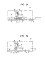
- Figs. 3A and 3B are schematic views illustrating states immediately before and after the tongue section 11 is installed on the buckle section 10.
- Fig. 3A illustrates a state immediately before the tongue section 11 is inserted into the buckle section 10
- Fig. 3B illustrates a state where the tongue section 11 is inserted and fixed to the buckle section 10.
- the buckle section 10 includes a frame 20 configuring a body and a slider 21 slidable to the frame 20 in an inserting direction of the tongue section 11.
- the slider 21 is slidable to the frame 20 via a first elastic member 22 and is always biased in a discharging direction of the tongue section 11 by the first elastic member 22. As illustrated in Fig. 3B , when the tongue section 11 is inserted into the buckle section 10, the slider 21 slides in the inserting direction against the bias of the first elastic member 22.
- the frame 20 rotatably supports the hook member 24.
- One end of the hook member 24 is fixed to the frame 20 and the hook member 24 is always biased to a lower surface side of the frame 20 by a second biasing member 25.
- a front end portion of the hook member 24 abuts an upper surface of the slider 21 and is stopped against the biasing of the second biasing member 25 before the tongue section 11 is inserted.
- Fig. 3B when the slider 21 slides in the inserting direction and the front end portion of the hook member 24 reaches to the hole-shaped engaging section 11a, the front end portion of the hook member 24 is rotated and is engaged with the engaging section 11a, and the tongue section 11 is held inside the buckle section 10 by the second biasing member 25.
- the frame 20 has a base plate 26 on a rear side in the inserting direction of the tongue section 11.
- a detection switch 27 forming a first switching unit as a switching unit which detects the detaching-installing state of the tongue section 11.
- the detection switch 27 includes a detection section 27a sliding with the slider 21 and has functions to switch connection states between a state when the tongue section 11 is not inserted and a state when the tongue section 11 is inserted, and to output signals different from each other. Detailed description of the detection switch 27 is given below.
- the detection switch 27 (the first switching unit) may be a switch device which is turned on when the switch is pushed and turned off when the switch is released from the pushed state.
- the detection switch 27 may be configured of a non-contact type sensor consisting of an optical sensor or a magnetic sensor.
- Fig. 4 is a block diagram of a vehicle side device 30 and a seat belt side device 40 for determining the installation state of the seat belt 3.
- the vehicle side device 30 is provided inside the vehicle 1 and the seat belt side device 40 is provided on the seat 2 and then both sides are wireless communicating with each other in both directions.
- the vehicle side device 30 has a vehicle side transmitting-receiving section 31 performing wireless communication with the seat belt side device 40 and a control section 32 including a determination section 32a determining the installation state of the seat belt 3, based on a detaching-installing signal (a signal B in Fig. 4 ) transmitted from the seat belt side device 40.
- the control section 32 has a trigger-operation detection section 33 which detects an operation corresponding to a timing to determine the installation state of the seat belt 3, that is, an operation of a trigger.
- the control section 32 outputs a command signal which instructs to output a request signal (a signal A in Fig. 4 ) described below with respect to the vehicle side transmitting-receiving section 31, when the trigger-operation detection section 33 detects the trigger operation.
- the vehicle side transmitting-receiving section 31 includes a transmitting antenna 31a and a receiving antenna 31b.
- the transmitting antenna 31a transmits a power feeding signal, which is served as the request signal to request to transmit the detaching-installing signal (the signal B in Fig. 4 ) to the seat belt side device 40.
- the power feeding signal is for feeding the power to the seat belt side device 40.
- the receiving antenna 31b receives the detaching-installing signal transmitted from the seat belt side device 40.
- the vehicle side transmitting-receiving section 31 gets in an actuation state from a sleep state by a command signal from the control section 32 and can perform the transmitting and receiving of the signal.
- the vehicle side transmitting-receiving section 31 outputs only the request signal to the seat belt side device 40.
- One trigger-operation detection section 33 is illustrated in Fig. 4 ; however, practically, a plurality of the trigger-operation detection sections are provided inside the vehicle 1 according to various types of the trigger operation.
- the trigger operation includes, for example, an open-close operation of a door of the vehicle 1, a cranking operation, a starting operation of an engine, or the like. Accordingly, the request signal is output to the vehicle side device at a necessary timing and can determine the installation state of the seat belt.
- the seat belt side device 40 includes a seat belt side transmitting-receiving section 41 performing the wireless communication with the vehicle side transmitting-receiving section 31 and an output unit 42 outputs the detaching-installing signal to the seat belt side transmitting-receiving section 41.
- the output unit 42 outputs the detaching-installing signal, based on whether or not the tongue section 11 is installed on the buckle section 10, that is, based on the ON and OFF of the detection switch 27.
- a vibrator 42a which is grounded and the detection switch 27 connected to a signal changing unit 42b which is grounded are connected in parallel with each other.
- the seat belt side transmitting-receiving section 41 includes an antenna 41a and the power is supplied to each configuration element of the seat belt side device 40 by receiving the power feeding signal from the vehicle side device 30 in the antenna 41a.
- the detaching-installing signal output from the output unit 42 is transmitted to the vehicle side device 30.
- the vehicle side device 30 and the seat belt side device 40 of the embodiment operate generally as below.
- the power feeding signal is transmitted from the vehicle side device 30.
- the seat belt side device 40 which receives the power feeding signal is configured such that the output unit 42 outputs the detaching-installing signal and transmits the detaching-installing signal to the vehicle side device 30.
- the detection switch 27 is ON state when the seat belt 3 is in the installation state, the output unit 42 is connected to the signal changing unit 42b and outputs a signal illustrated in Fig. 6B as described below.
- the output unit 42 since the output unit 42 is not connected to the signal changing unit 42b by the detection switch 27 when the seat belt 3 is in a non-installation state, the output unit 42 outputs a signal illustrated in Fig. 6A as described below,. As described above, since the output unit 42 outputs the signal according to the connection state between the detection switch 27 and the signal changing unit 42b, the vehicle side device 30 can determine the detaching-installing signal of the seat belt 3 by detecting the difference between signal frequencies.
- Fig. 5 is a circuit diagram illustrating a configuration of the seat belt side device 40 illustrated in Fig. 4 .
- the seat belt side transmitting-receiving section 41 is configured of the antenna 41a and a RF circuit section 41b.
- the RF circuit section 41b is a modem circuit section and is connected in series with a resonant circuit section which is the output unit 42.
- the resonant circuit section is configured such that the vibrator 42a is connected in parallel with the signal changing unit 42b and they are grounded.
- the signal changing unit 42b is configured of a capacitor having a predetermined capacitance value.
- Fig. 6 is a waveform view of a signal output from the output unit 42.
- Fig. 6A illustrates a state where the vibrator is not connected to the signal changing unit 42b, in other words, illustrates a signal of the non-installation state of the seat belt 3.
- natural resonant frequency of the vibrator 42a is a resonant frequency of the oscillation circuit directly and the signal of the frequency is output.
- the signal is attenuated at a constant rate with the progress of time; however, the frequency is constant regardless of the progress of time.
- Fig. 6B illustrates the signal of a state where the vibrator 42a is connected to the signal changing unit 42b, in other words, the signal of the installation state of the seat belt 3.
- the vibrator 42a is connected to the capacitor that is the signal changing unit 42b, since the resonant frequency of the oscillation circuit is changed, the frequency of the output signal is different from Fig. 6A .
- the attenuation rate of the signal with the progress of time is the same as Fig. 6A .
- the determination section 32a of the vehicle side device 30 can determine the state of the detection switch 27, in other words, the installation state of the seat belt 3 by detecting the frequency of the received detaching-installing signal.
- the determination section 32a of the vehicle side device 30 can determine the state of the detection switch 27, in other words, the installation state of the seat belt 3 by detecting the frequency of the received detaching-installing signal.
- the installation state of the seat belt 3 on each seat can be easily determined by the frequency in the determination section 32a.
- Fig. 7 is a chart diagram of the signal in communication between the vehicle side device 30 and seat belt side device 40.
- the vehicle side transmitting-receiving section 31 is from the sleep state to the actuation state by the command signal output from the communication section 15 and the power feeding signal is transmitted intermittently several times.
- the vehicle side transmitting-receiving section 31 is ready to receive the signal which is output from the seat belt side device 40 when the power feeding signal is transmitted intermittently.
- the seat belt side device 40 transmits intermittently the detaching-installing signal to the vehicle side device 30 in response to the power feeding signal from the vehicle side device 30.
- reference numerals S1 to S4 are referred to the signals transmitted from the seat belt side device 40 and the seat belt is in the installation state from the non-installation state after the signal S2 among them is transmitted, and the seat belt 3 is in the non-installation state from the installation state after the signal S3 is transmitted.
- the detection switch 27 When the seat belt 3 is in the installation state from the non-installation state, the detection switch 27 is turned on from off and, as described above, the signal S3 output from the seat belt side device 40 is the signal having a frequency different from when the seat belt 3 is in the non-installation state.
- the signal S3 in Fig. 7 is different from the signal S1 or S2 corresponding to Fig. 6A and is the signal having the frequency corresponding to Fig. 6B . Accordingly, the determination section 32a of the vehicle side device 30 recognizes that the seat belt 3 is in the installation state.
- the detection switch 27 is turned off from on and the signal S4 output from the seat belt side device 40 is a signal having a frequency different from when the seat belt 3 is in the installation state.
- the signal S4 in Fig. 7 is a signal having the frequency different from S3 and the same as S1 or S2. Accordingly, the determination section 32a of the vehicle side device 30 recognizes that the seat belt 3 is in the non-installation state.
- Fig. 8 is a flowchart determining the installation state of the seat belt 3.
- the control section 32 of the vehicle side device 30 detects present or absent of the trigger operation (S1).
- the trigger operation is detected by the trigger-operation detection section 33 as described above.
- the vehicle side transmitting-receiving section 31 is ready to receive the signal (S2).
- the trigger operation is not detected at S1, the operation of S1 is repeated until a predetermined time is lapsed (S1-1).
- S2 is performed similar to the case where the trigger operation is present.
- the power feeding signal modulated from the vehicle side transmitting-receiving section 31 is transmitted (S3).
- the power feeding signal is transmitted intermittently several times.
- 1 is added to a variable n (S4). This is intended to count the number of times of the power feeding signal being transmitted.
- the signal when the power feeding signal is received, the signal is demodulated by the power supply of the power feeding signal, the detaching-installing signal is output from the output unit 42 according to the connection state between the detection switch 27 and the signal changing unit 42b, and the detaching-installing signal is transmitted from the seat belt side transmitting-receiving section 41 (S5).
- the determination section 32a makes the variable n to 0 (S7). Meanwhile, when the vehicle side transmitting-receiving section 31 cannot receive the signal from the seat belt side device 40, the control section 32 (the determination section 32a) further detects the operation state of the engine (S6-1) and S3 to S6 are repeated when the engine is operated. When the engine is not operated at S6-1, whether or not the variable n is smaller than a predetermined value N is determined, in other words, whether or not the number of the transmissions of the power feeding signal reaches a predetermined number is determined (S6-2).
- the control section 32 determines the detaching-installing state of the seat belt 3, based on the detaching-installing signal received from the seat belt side device 40 (S8).
- the detaching-installing state of the seat belt 3 is determined by the frequency of the detaching-installing signal which is received by the seat belt side device 40.
- the determination section 32a determines that the seat belt 3 is in the installation state (S9), otherwise, the determination section 32a determines that the seat belt 3 is in the non-installation state (S10).
- the determined states are displayed on an instrument panel or the like of a driver's seat through a system inside the vehicle. When the determination is performed, the operation is repeated from the beginning.
- the power, required for operation in the seat belt side device 40 is supplied by the power feeding signal from the vehicle side device 30 to the seat belt side device 40 in order to determine the installation state of the seat belt 3 provided on the detachable seat 2. Accordingly, it is not necessary to provide the battery on the seat 2 side and to exchange the battery. In addition, it is possible to determine the detaching-installing state of the seat belt 3 at any time and in a short time.
- the signal transmitted from the seat belt side device 40 is changed only by providing the signal changing unit 42b consisting of the detection switch 27 which is switched by the installation state of the seat belt 3 and the capacitor so that the installation state of the seat belt 3 can be determined the installation state of the seat belt 3 with a simple structure.
- the capacitor is used as the signal changing unit 42b in Fig. 5 ; however, a resistance instead of the capacitor may be used as the signal changing unit 42b.
- the vibrator 42a is in the connection state by the detection switch 27 and then the impedance is changed in the oscillation circuit so that the frequency of the output signal is not changed and the attenuation rate is changed.
- Fig. 9 is a waveform diagram of a signal output from the output unit 42 in a case where the signal change unit 42b is the resistance.
- Fig. 9(a) illustrates a state where the first detection switch 27 is turned off and the vibrator 42a is not connected to the signal changing unit 42b, in other words, illustrates the signal of the non-installation state of the seat belt 3, and is the same as Fig. 6A .
- Fig. 9(b) illustrates a state where the first detection switch 27 is turned on and the vibrator 42a is connected to the signal changing unit 42b consisting of the resistance, in other words, illustrates the signal of the installation state of the seat belt 3.
- the attenuation rate of the signal is large with the progress of time compared to the case of Fig. 9A .
- the determination section 32a of the vehicle side device 30 can determine the installation state of the seat belt 3 by detecting the attenuation rate of the signal from the seat belt side device 40.
- Fig. 10 is a perspective view of the detachable seat 2.
- a seat sensor 50 is provided inside the seat surface of the seat 2 as a second switching unit which detecting presence or absence of seating, in other words, the presence or absence of the load applied on the seat 2.
- the seat sensor 50 is configured such that a electrode seat is laminated on an upper surface or a lower surface of a pressure sensitive rubber seat.
- Fig. 11 is a circuit diagram illustrating a configuration of the seat belt side device 40 in a case where both of the detaching-installing state of the seat belt 3 and a seated state of the seat 2 are detected.
- the seat sensor 50 is illustrated as a single switch.
- the seat sensor 50 as the second switching unit is connected in parallel with the detection switch 27 which is the first switch unit and a second signal changing unit 42c consisting of the resistance is connected in series with the seat sensor 50.
- the output unit 42 is configured such that the grounded vibrator 42a, the grounded first signal changing unit 42b and the grounded second signal changing unit 42c are connected in parallel with each other.
- the connection state between the vibrator 42a and the signal changing unit 42b is changed by the detection switch 27 being turned on and off , and the frequency of the output signal is changed.
- the connection state between the vibrator 42a and the second signal changing unit 42c is changed by the change in the output of the seat sensor 50, and the attenuation rate of the output signal is changed.
- the vibrator 42a is connected to both of the signal changing unit 42b and the second signal changing unit 42c and the output signal is a signal which is different in both the frequency and the attenuation rate. Accordingly, the vehicle side device 30 can determine both of the installation state of the seat belt 3 and the seated state of the seat 2 by detecting the frequency and the attenuation rate of the signal from the seat belt side device 40.
- the combining of the capacitor and the resistance to the signal changing unit 42b and the second signal changing unit 42c may be selected arbitrarily.
- the signal changing unit 42b may be the resistance
- the second signal changing unit 42c may be the capacitor
- both of them may be the resistance or both of them may be the capacitor.
- signals of four patterns having different attenuation rates can be generated by using the resistances having resistance values different from each other in the combination.
- signals of four patterns having different frequencies can be generated by using the capacitances having capacitance values different from each other.
- Fig. 12 is a block diagram of the vehicle side device 30 and the seat belt side device 40 using the RFID.
- the vehicle side device 30 has a RFID reader ⁇ writer 60 as the vehicle side transmitting-receiving section.
- the RFID reader ⁇ writer 60 makes the transmitting and receiving of the signal to be controlled by a control section 61.
- a trigger-operation detection section 63 and an output section 62 are connected to the control section 61.
- the seat belt side device 40 has a RFID tag 70 as the seat belt side transmitting-receiving section.
- the RFID tag 70 includes a modem section 71, a rectification section 72, a control section 73, a memory 74 and an AD converter 75.
- the detection switch 27 as the switching unit is connected to the control section 73.
- the seat sensor 50 of the seat 2 is connected to the AD converter 75.
- the detection switch 27 is a switch which simply switches ON and OFF, the AD converter 75 is not necessary.
- the power is supplied to the seat belt side device 40 by the power feeding signal from the RFID reader ⁇ writer 60 that is the vehicle side transmitting-receiving section.
- the control section 73 detects the detaching-installing state of the seat belt 3 by the state of the detection switch 27 and detects the seated state of the seat 2 via the AD converter 75 by the state of the seat sensor 50, and transmits the information including the transmitting signal to the vehicle side device 30.
- the vehicle side device 30, which receives the signal from the seat belt side device 40, and outputs the installation state of the seat belt 3 and the seated state of the seat 2 from the output section 62.
- the output information is displayed on the displayed on the instrument panel or the like of a driver's seat through the system inside the vehicle.
- the configuration of the apparatus can be simplified with low cost.
- the seat belt according to the embodiment of the invention an example is described, which is installed on the detachable seats 2 of the last row in three rows provided in the room of the vehicle; however, of course, the invention may be applied to the front row seat (the driver's seat and the passenger's seat) which is not detachable or applied to the seat row which is positioned back of the front seat.
- the power feeding signal described above is not necessary.
- the application of the invention is not limited to the embodiments and may be applied in various ways within the scope of the technical idea of the invention.
Abstract
A vehicle includes a vehicle side device (30) having a vehicle side transmitting-receiving section (31) performing wireless communicating with a seat belt side and a control section (32) (determination section (32a)) determining an installation state, based on a signal from the seat belt side; and a seat belt side device (40) having a seat belt side transmitting-receiving section (41) performing wireless communicating with the vehicle side, a first switching unit (27) of which switches the state according to detaching and installing of the seat belt and an output unit (42) which outputs a detaching-installing signal to the seat belt side transmitting-receiving section in response to the state of the first switching unit. A power is fed to the seat belt side transmitting-receiving section (41) and the output unit (42), and the signal is output and transmitted by the signal form the vehicle side transmitting-receiving section (31).
Description
- This application claims benefit of Japanese Patent Application No.
2012-117902 filed on May 23, 2012 - The present invention relates to a vehicle including a seat belt which detects an installation state in a vehicle side by wireless communicating with the vehicle.
- In the related art, a technique has been known which displays an installation state of a seat belt by detecting the installation state thereof. In this case, the detection of the installation state is performed by a buckle switch provided inside a buckle device configuring the seat belt. Accordingly, when detecting that the installation state is performed, a signal is wirelessly transmitted from the seat belt to a control section of the vehicle and the control such as display is performed.
- The vehicle including such a seat belt is, for example, disclosed in Japanese Unexamined Patent Application Publication No.
2008-238947 - In the vehicle including such a seat belt of the related art, the signal from the first transmitter requires a data signal for identifying the seat having the seat belt and the signal from the second transmitter requires a preamble signal in which the receiver of the vehicle side switches from an intermittent operation state to a continuous operation state. Furthermore, since the receiver of the vehicle side is necessary to receive the signal from the first transmitter, after the signal is received from the second receiver in order to determine whether the seat belt is installed, there is a problem that the wireless communication time between each of the transmitters and the receivers becomes long.
- The present invention provides a vehicle including a seat belt in which wireless communication time between the seat belt side and the vehicle side can be shortened.
- A vehicle including a seat belt according to an embodiment of the invention, has a seat belt which is provided on a seat and a vehicle side device wireless communicating with the seat belt side and determining an installation state of the seat belt, wherein the seat belt includes a seat belt side transmitting-receiving section which transmits a detaching-installing signal indicating whether or not the seat belt is in the installation state to the vehicle side device when receiving a request signal transmitted from the vehicle side device, and an output unit which outputs the detaching-installing signal to the seat belt side transmitting-receiving section, and wherein the vehicle side device includes vehicle side transmitting-receiving section which transmits the request signal to the seat belt side transmitting-receiving section and receives the detaching-installing signal, and a control section which controls the vehicle side transmitting-receiving section so as to output the request signal and determines the installation state of the seat belt, based on the detaching-installing signal.
- In the vehicle including the seat belt according to an embodiment of the invention, the seat belt side transmitting-receiving section may have a RF circuit section, the output unit may have a resonant circuit section connected to the RF circuit section and the resonant circuit section in which a grounded vibrator and a grounded signal changing unit are connected in parallel with each other and which may have a switching unit switching the connection state between the vibrator and the signal changing unit.
- In the vehicle including the seat belt according to an embodiment of the invention, the signal changing unit may be configured of a first signal changing unit and a second signal changing unit which are connected in parallel with each other, the switching unit may be configured of a first switching unit which is connected in series with the first signal changing unit and a second switching unit which is connected in series with the second signal changing unit, and the first signal changing unit may be provided on the seat belt and the second signal changing unit is provided on the seat.
- In the vehicle including the seat belt according to an embodiment of the invention, the first signal changing unit may be configured of any one of a capacitor and a resistance, and the second signal changing unit is configured of the other of the capacitor and the resistance.
- In the vehicle including the seat belt according to an embodiment of the invention, the vehicle side device may include a trigger-operation detection section which detects a trigger operation corresponding to a timing when the installation state of the seat belt is determined, and the trigger-operation detection section may be connected to the control section and the control section instructs the vehicle side transmitting-receiving section to output the request signal when the signal is input from the trigger-operation detection section.
- In the vehicle including the seat belt according to an embodiment of the invention, the vehicle side transmitting-receiving section is configured of a RFID reader·writer, and the seat belt side transmitting-receiving section and the output unit may be configured of a RFID tag, and the switching unit is connected to the RFID tag.
- In the vehicle including the seat belt according to an embodiment of the invention, the switching unit may be configured of a detection switch provided inside a buckle section consisting of the seat belt.
- According to the vehicle including the seat belt relating to the invention, the seat belt side transmitting-receiving section can transmit immediately the detaching-installing signal to the vehicle side device, when the request signal transmitted from the vehicle side device is received and the vehicle side device can determine the installation state of the seat belt, based on the detaching-installing signal. Accordingly, the vehicle including the seat belt can be provided in which the wireless communication time between the seat belt side and the vehicle side can be shortened. In addition, since the request signal can be output to the vehicle side device at any time, it is possible to determine the installation state of the seat belt at a necessary timing. Furthermore, the invention is preferably applied to a flip-up type seat.
- According to the vehicle including the seat belt relating to the invention, the signal output from the output unit is changed by the switching of the switching unit. Accordingly, the installation state of the seat belt can be determined by the signal change in the control section. For example, when the capacitor is used as the signal changing unit, since the frequency of the signal output from the output unit is changed, the installation state of the seat belt can be determined by the change of the frequency in the control section. In addition, when the resistance is used as the signal changing unit, since the attenuation rate of the signal output from the output unit is changed, the installation state of the seat belt can be determined by the change of the attenuation rate in the control section. In addition, the installation state of the seat belt in each seat can be determined with a simple configuration by changing the capacitance value of the capacitor or the resistance value of the resistance for each seat, respectively, without applying the identification signal.
- According to the vehicle including the seat belt relating to the invention, the signal which is changed by the switching state of the first switching unit is determined in the control section so that the installation state of the seat belt can be determined. In addition, the signal which is changed by switching state of the second switching unit is determined in the control section and the seated state of a person can be determined so that whether or not the person seated on the seat is restrained by the seat belt is reliably determined.
- According to the vehicle including the seat belt relating to the invention, it is possible to determine reliably whether or not the person seated on the seat is restrained by the seat belt, based on the change of the frequency and the attenuation rate of the output signal from the output unit with a simple structure.
- According to the vehicle including the seat belt relating to the invention, the installation state of the seat belt can be determined at the timing to determine the installation state of the seat belt.
- According to the vehicle including the seat belt relating to the invention, the battery is not necessarily mounted on the seat belt side. Accordingly, the seat belt can be simplified with low cost.
- According to the vehicle including the seat belt relating to the invention, the installation state of the seat belt can be determined with a simple structure.
-
-
Fig. 1 is a schematic view of a vehicle in an embodiment. -
Fig. 2 is a perspective view illustrating a buckle section and a tongue section before a seat belt is installed. -
Figs. 3A and 3B are schematic cross-sectional views before and after the seat belt is installed. -
Fig. 4 is a block diagram of a vehicle side device and a seat belt side device to determine an installation state of the seat belt. -
Fig. 5 is a circuit diagram illustrating a configuration of the seat belt side device. -
Figs. 6A and 6B are waveform diagrams of a signal output from an output unit. -
Fig. 7 is a chart diagram of a signal in communication between the vehicle side device and the seat belt side device. -
Fig. 8 is a flowchart determining an installation state of the seat belt. -
Figs. 9A and 9B are waveform diagrams of a signal output from an output unit in a case where a signal change unit is resistance. -
Fig. 10 is a perspective view of a detachable seat. -
Fig. 11 is a circuit diagram illustrating a configuration of the seat belt side device in a case where both of an installation state of the seat belt and a seated state of the seat are detected. -
Fig. 12 is a block diagram of the vehicle side device and the seat belt side device using a RFID. - An embodiment of the invention will be described in detail with reference to the drawings.
Fig. 1 is a schematic view of a vehicle in the embodiment. As illustrated in the view, avehicle 1 in the embodiment illustrates, for example, a RV vehicle and includes a plurality ofseats 2 in a room. Theseats 2 is provided three rows in the room, theseats 2 of the last row is detachably provided such as folding type, flip-up type and removing type, and aseat belt 3 is provided on theseat 2. Theseat belt 3 is mainly configured of abelt 12, awinding section 13 winding thebelt 12, atongue section 11 provided a front end of thebelt 12, abuckle section 10 detaching and installing thetongue section 11 and a seatbelt side device 40 performing wireless communication with a vehicle side device described below. - The
seat belt 3 provided on theseats 2 is configured such that thebelt 12 is drawn from thewinding section 13 provided on a shoulder of a man seated on theseats 2 toward thebuckle section 10 provided in the vicinity of a waist of the man. Theseat belt 3 is configured such that thebelt 12 is drawn from thewinding section 13 and thetongue section 11 is inserted and fixed to thebuckle section 10, when installing theseat belt 3. In addition, when releasing the installing of theseat belt 3, thetongue section 11 is removed from thebuckle section 10 and thebelt 12 is wound on the shoulder side. As illustrated inFig. 2 , thetongue section 11 has anengaging section 11a which engages with a front end of ahook member 24 described below. -
Figs. 3A and 3B are schematic views illustrating states immediately before and after thetongue section 11 is installed on thebuckle section 10.Fig. 3A illustrates a state immediately before thetongue section 11 is inserted into thebuckle section 10 andFig. 3B illustrates a state where thetongue section 11 is inserted and fixed to thebuckle section 10. - The
buckle section 10 includes aframe 20 configuring a body and aslider 21 slidable to theframe 20 in an inserting direction of thetongue section 11. Theslider 21 is slidable to theframe 20 via a firstelastic member 22 and is always biased in a discharging direction of thetongue section 11 by the firstelastic member 22. As illustrated inFig. 3B , when thetongue section 11 is inserted into thebuckle section 10, theslider 21 slides in the inserting direction against the bias of the firstelastic member 22. - The
frame 20 rotatably supports thehook member 24. One end of thehook member 24 is fixed to theframe 20 and thehook member 24 is always biased to a lower surface side of theframe 20 by asecond biasing member 25. - As illustrated in
Fig. 3A , a front end portion of thehook member 24 abuts an upper surface of theslider 21 and is stopped against the biasing of the second biasingmember 25 before thetongue section 11 is inserted. As illustrated inFig. 3B , when theslider 21 slides in the inserting direction and the front end portion of thehook member 24 reaches to the hole-shapedengaging section 11a, the front end portion of thehook member 24 is rotated and is engaged with the engagingsection 11a, and thetongue section 11 is held inside thebuckle section 10 by the second biasingmember 25. - In a state where the
tongue section 11 is held inside thebuckle section 10, when arelease button 23 illustrated inFig. 2 is operated to push, thehook member 24 is lifted up by a release mechanism (not illustrated), an engaging state to thetongue section 11 is released, theslider 21 slides in the discharging direction by a biasing force of the firstelastic member 22, and then thetongue section 11 is disposed outside thebuckle section 10. - The
frame 20 has abase plate 26 on a rear side in the inserting direction of thetongue section 11. In thebase plate 26, parts for the wireless communication described below are disposed and adetection switch 27 forming a first switching unit as a switching unit which detects the detaching-installing state of thetongue section 11. Thedetection switch 27 includes adetection section 27a sliding with theslider 21 and has functions to switch connection states between a state when thetongue section 11 is not inserted and a state when thetongue section 11 is inserted, and to output signals different from each other. Detailed description of thedetection switch 27 is given below. - In addition, the detection switch 27 (the first switching unit) may be a switch device which is turned on when the switch is pushed and turned off when the switch is released from the pushed state. In addition, the
detection switch 27 may be configured of a non-contact type sensor consisting of an optical sensor or a magnetic sensor. - Next, configuration for determining the installation state of the
seat belt 3, in other words, whether or not theseat belt 3 is installed so as to restrain a driver is described.Fig. 4 is a block diagram of avehicle side device 30 and a seatbelt side device 40 for determining the installation state of theseat belt 3. Thevehicle side device 30 is provided inside thevehicle 1 and the seatbelt side device 40 is provided on theseat 2 and then both sides are wireless communicating with each other in both directions. - The
vehicle side device 30 has a vehicle side transmitting-receivingsection 31 performing wireless communication with the seatbelt side device 40 and acontrol section 32 including adetermination section 32a determining the installation state of theseat belt 3, based on a detaching-installing signal (a signal B inFig. 4 ) transmitted from the seatbelt side device 40. Thecontrol section 32 has a trigger-operation detection section 33 which detects an operation corresponding to a timing to determine the installation state of theseat belt 3, that is, an operation of a trigger. In addition, thecontrol section 32 outputs a command signal which instructs to output a request signal (a signal A inFig. 4 ) described below with respect to the vehicle side transmitting-receivingsection 31, when the trigger-operation detection section 33 detects the trigger operation. - The vehicle side transmitting-receiving
section 31 includes a transmittingantenna 31a and a receivingantenna 31b. The transmittingantenna 31a transmits a power feeding signal, which is served as the request signal to request to transmit the detaching-installing signal (the signal B inFig. 4 ) to the seatbelt side device 40. The power feeding signal is for feeding the power to the seatbelt side device 40. Meanwhile, the receivingantenna 31b receives the detaching-installing signal transmitted from the seatbelt side device 40. The vehicle side transmitting-receivingsection 31 gets in an actuation state from a sleep state by a command signal from thecontrol section 32 and can perform the transmitting and receiving of the signal. In addition, when a battery is mounted on the seatbelt side device 40 side, since the power feeding signal is not necessary to be transmitted to the seatbelt side device 40, the vehicle side transmitting-receivingsection 31 outputs only the request signal to the seatbelt side device 40. - One trigger-
operation detection section 33 is illustrated inFig. 4 ; however, practically, a plurality of the trigger-operation detection sections are provided inside thevehicle 1 according to various types of the trigger operation. The trigger operation includes, for example, an open-close operation of a door of thevehicle 1, a cranking operation, a starting operation of an engine, or the like. Accordingly, the request signal is output to the vehicle side device at a necessary timing and can determine the installation state of the seat belt. - The seat
belt side device 40 includes a seat belt side transmitting-receivingsection 41 performing the wireless communication with the vehicle side transmitting-receivingsection 31 and anoutput unit 42 outputs the detaching-installing signal to the seat belt side transmitting-receivingsection 41. As illustrated inFig. 5 , theoutput unit 42 outputs the detaching-installing signal, based on whether or not thetongue section 11 is installed on thebuckle section 10, that is, based on the ON and OFF of thedetection switch 27. In addition, avibrator 42a which is grounded and thedetection switch 27 connected to asignal changing unit 42b which is grounded are connected in parallel with each other. - The seat belt side transmitting-receiving
section 41 includes anantenna 41a and the power is supplied to each configuration element of the seatbelt side device 40 by receiving the power feeding signal from thevehicle side device 30 in theantenna 41a. In addition, the detaching-installing signal output from theoutput unit 42 is transmitted to thevehicle side device 30. - The
vehicle side device 30 and the seatbelt side device 40 of the embodiment operate generally as below. First when the trigger operation is detected, the power feeding signal is transmitted from thevehicle side device 30. The seatbelt side device 40 which receives the power feeding signal is configured such that theoutput unit 42 outputs the detaching-installing signal and transmits the detaching-installing signal to thevehicle side device 30. At this time, since thedetection switch 27 is ON state when theseat belt 3 is in the installation state, theoutput unit 42 is connected to thesignal changing unit 42b and outputs a signal illustrated inFig. 6B as described below. In addition, since theoutput unit 42 is not connected to thesignal changing unit 42b by thedetection switch 27 when theseat belt 3 is in a non-installation state, theoutput unit 42 outputs a signal illustrated inFig. 6A as described below,. As described above, since theoutput unit 42 outputs the signal according to the connection state between thedetection switch 27 and thesignal changing unit 42b, thevehicle side device 30 can determine the detaching-installing signal of theseat belt 3 by detecting the difference between signal frequencies. -
Fig. 5 is a circuit diagram illustrating a configuration of the seatbelt side device 40 illustrated inFig. 4 . Since the power feeding signal serving as the request signal transmitted from thevehicle side device 30 is a RF signal, the seat belt side transmitting-receivingsection 41 is configured of theantenna 41a and aRF circuit section 41b. TheRF circuit section 41b is a modem circuit section and is connected in series with a resonant circuit section which is theoutput unit 42. The resonant circuit section is configured such that thevibrator 42a is connected in parallel with thesignal changing unit 42b and they are grounded. Thesignal changing unit 42b is configured of a capacitor having a predetermined capacitance value. - The power feeding signal received by the
antenna 41a is demodulated in theRF circuit section 41b and becomes a signal of a predetermined frequency by thevibrator 42a of theoutput unit 42.Fig. 6 is a waveform view of a signal output from theoutput unit 42.Fig. 6A illustrates a state where the vibrator is not connected to thesignal changing unit 42b, in other words, illustrates a signal of the non-installation state of theseat belt 3. - When the
vibrator 42a is not connected to thesignal changing unit 42b, natural resonant frequency of thevibrator 42a is a resonant frequency of the oscillation circuit directly and the signal of the frequency is output. The signal is attenuated at a constant rate with the progress of time; however, the frequency is constant regardless of the progress of time. -
Fig. 6B illustrates the signal of a state where thevibrator 42a is connected to thesignal changing unit 42b, in other words, the signal of the installation state of theseat belt 3. As illustrated in the view, when thevibrator 42a is connected to the capacitor that is thesignal changing unit 42b, since the resonant frequency of the oscillation circuit is changed, the frequency of the output signal is different fromFig. 6A . However, the attenuation rate of the signal with the progress of time is the same asFig. 6A . - As described above, the
determination section 32a of thevehicle side device 30 can determine the state of thedetection switch 27, in other words, the installation state of theseat belt 3 by detecting the frequency of the received detaching-installing signal. In addition, when each capacitor as thesignal changing unit 42b having different capacitance value is provided for each seat, since the signal frequencies inFig. 6 are different from each other in the installation state of theseat belt 3, the installation state of theseat belt 3 on each seat can be easily determined by the frequency in thedetermination section 32a. - The operation of the
vehicle side device 30 and the seatbelt side device 40 is described in further detail.Fig. 7 is a chart diagram of the signal in communication between thevehicle side device 30 and seatbelt side device 40. When the trigger operation is detected in the trigger-operation detection section 33, the vehicle side transmitting-receivingsection 31 is from the sleep state to the actuation state by the command signal output from the communication section 15 and the power feeding signal is transmitted intermittently several times. In addition, the vehicle side transmitting-receivingsection 31 is ready to receive the signal which is output from the seatbelt side device 40 when the power feeding signal is transmitted intermittently. - The seat
belt side device 40 transmits intermittently the detaching-installing signal to thevehicle side device 30 in response to the power feeding signal from thevehicle side device 30. InFig. 7 , reference numerals S1 to S4 are referred to the signals transmitted from the seatbelt side device 40 and the seat belt is in the installation state from the non-installation state after the signal S2 among them is transmitted, and theseat belt 3 is in the non-installation state from the installation state after the signal S3 is transmitted. - When the
seat belt 3 is in the installation state from the non-installation state, thedetection switch 27 is turned on from off and, as described above, the signal S3 output from the seatbelt side device 40 is the signal having a frequency different from when theseat belt 3 is in the non-installation state. In other words, the signal S3 inFig. 7 is different from the signal S1 or S2 corresponding toFig. 6A and is the signal having the frequency corresponding toFig. 6B . Accordingly, thedetermination section 32a of thevehicle side device 30 recognizes that theseat belt 3 is in the installation state. - Meanwhile, when the
seat belt 3 is in the non-installation state from the installation state, thedetection switch 27 is turned off from on and the signal S4 output from the seatbelt side device 40 is a signal having a frequency different from when theseat belt 3 is in the installation state. In other words, the signal S4 inFig. 7 is a signal having the frequency different from S3 and the same as S1 or S2. Accordingly, thedetermination section 32a of thevehicle side device 30 recognizes that theseat belt 3 is in the non-installation state. -
Fig. 8 is a flowchart determining the installation state of theseat belt 3. When the flow is started, thecontrol section 32 of thevehicle side device 30 detects present or absent of the trigger operation (S1). The trigger operation is detected by the trigger-operation detection section 33 as described above. When the trigger operation is detected at S1, the vehicle side transmitting-receivingsection 31 is ready to receive the signal (S2). When the trigger operation is not detected at S1, the operation of S1 is repeated until a predetermined time is lapsed (S1-1). When a printed time is lapsed, S2 is performed similar to the case where the trigger operation is present. - When the vehicle side transmitting-receiving
section 31 is ready to receive the signal, the power feeding signal modulated from the vehicle side transmitting-receivingsection 31 is transmitted (S3). Here as illustrated inFig. 7 , the power feeding signal is transmitted intermittently several times. Sequentially, in thedetermination section - In the seat
belt side device 40, as described above, when the power feeding signal is received, the signal is demodulated by the power supply of the power feeding signal, the detaching-installing signal is output from theoutput unit 42 according to the connection state between thedetection switch 27 and thesignal changing unit 42b, and the detaching-installing signal is transmitted from the seat belt side transmitting-receiving section 41 (S5). - When the vehicle side transmitting-receiving
section 31 receives the signal from the seat belt side device 40 (S6), thedetermination section 32a makes the variable n to 0 (S7). Meanwhile, when the vehicle side transmitting-receivingsection 31 cannot receive the signal from the seatbelt side device 40, the control section 32 (thedetermination section 32a) further detects the operation state of the engine (S6-1) and S3 to S6 are repeated when the engine is operated. When the engine is not operated at S6-1, whether or not the variable n is smaller than a predetermined value N is determined, in other words, whether or not the number of the transmissions of the power feeding signal reaches a predetermined number is determined (S6-2). When the number of the transmissions of the power feeding signal is smaller than a predetermined number, the operation is repeated from S1. When the number of the transmissions of the power feeding signal is the predetermined number or more, error occurs (S6-3). The state of the generation of the error is displayed on the instrument panel of the driver's seat through the system inside the vehicle. - When S7 is performed, next, the
control section 32 determines the detaching-installing state of theseat belt 3, based on the detaching-installing signal received from the seat belt side device 40 (S8). In the embodiment, as described above, the detaching-installing state of theseat belt 3 is determined by the frequency of the detaching-installing signal which is received by the seatbelt side device 40. Here, when the detaching-installing state is a signal indicating "installing", thedetermination section 32a determines that theseat belt 3 is in the installation state (S9), otherwise, thedetermination section 32a determines that theseat belt 3 is in the non-installation state (S10). The determined states are displayed on an instrument panel or the like of a driver's seat through a system inside the vehicle. When the determination is performed, the operation is repeated from the beginning. - As described above, in the
vehicle 1 including theseat belt 3, the power, required for operation in the seatbelt side device 40 is supplied by the power feeding signal from thevehicle side device 30 to the seatbelt side device 40 in order to determine the installation state of theseat belt 3 provided on thedetachable seat 2. Accordingly, it is not necessary to provide the battery on theseat 2 side and to exchange the battery. In addition, it is possible to determine the detaching-installing state of theseat belt 3 at any time and in a short time. In addition, the signal transmitted from the seatbelt side device 40 is changed only by providing thesignal changing unit 42b consisting of thedetection switch 27 which is switched by the installation state of theseat belt 3 and the capacitor so that the installation state of theseat belt 3 can be determined the installation state of theseat belt 3 with a simple structure. - The capacitor is used as the
signal changing unit 42b inFig. 5 ; however, a resistance instead of the capacitor may be used as thesignal changing unit 42b. When the resistance is thesignal changing unit 42b, thevibrator 42a is in the connection state by thedetection switch 27 and then the impedance is changed in the oscillation circuit so that the frequency of the output signal is not changed and the attenuation rate is changed. -
Fig. 9 is a waveform diagram of a signal output from theoutput unit 42 in a case where thesignal change unit 42b is the resistance.Fig. 9(a) illustrates a state where thefirst detection switch 27 is turned off and thevibrator 42a is not connected to thesignal changing unit 42b, in other words, illustrates the signal of the non-installation state of theseat belt 3, and is the same asFig. 6A .Fig. 9(b) illustrates a state where thefirst detection switch 27 is turned on and thevibrator 42a is connected to thesignal changing unit 42b consisting of the resistance, in other words, illustrates the signal of the installation state of theseat belt 3. As illustrated in the views, in the output signal from theoutput unit 42, the attenuation rate of the signal is large with the progress of time compared to the case ofFig. 9A . Thedetermination section 32a of thevehicle side device 30 can determine the installation state of theseat belt 3 by detecting the attenuation rate of the signal from the seatbelt side device 40. - In addition, it is possible to determine whether or not a person is seated as well as the installation state of the
seat belt 3 in theseat 2.Fig. 10 is a perspective view of thedetachable seat 2. As illustrated in the view, aseat sensor 50 is provided inside the seat surface of theseat 2 as a second switching unit which detecting presence or absence of seating, in other words, the presence or absence of the load applied on theseat 2. Theseat sensor 50 is configured such that a electrode seat is laminated on an upper surface or a lower surface of a pressure sensitive rubber seat. -
Fig. 11 is a circuit diagram illustrating a configuration of the seatbelt side device 40 in a case where both of the detaching-installing state of theseat belt 3 and a seated state of theseat 2 are detected. In addition, inFig. 11 , for the sake of convenience, theseat sensor 50 is illustrated as a single switch. - As illustrated in
Fig. 11 , theseat sensor 50 as the second switching unit is connected in parallel with thedetection switch 27 which is the first switch unit and a secondsignal changing unit 42c consisting of the resistance is connected in series with theseat sensor 50. As described above, theoutput unit 42 is configured such that the groundedvibrator 42a, the grounded firstsignal changing unit 42b and the grounded secondsignal changing unit 42c are connected in parallel with each other. - In a case of
Fig. 11 , the connection state between thevibrator 42a and thesignal changing unit 42b is changed by thedetection switch 27 being turned on and off , and the frequency of the output signal is changed. Meanwhile, the connection state between thevibrator 42a and the secondsignal changing unit 42c is changed by the change in the output of theseat sensor 50, and the attenuation rate of the output signal is changed. In addition, when a person is seated on theseat 2 and theseat belt 3 is installed, thevibrator 42a is connected to both of thesignal changing unit 42b and the secondsignal changing unit 42c and the output signal is a signal which is different in both the frequency and the attenuation rate. Accordingly, thevehicle side device 30 can determine both of the installation state of theseat belt 3 and the seated state of theseat 2 by detecting the frequency and the attenuation rate of the signal from the seatbelt side device 40. - The combining of the capacitor and the resistance to the
signal changing unit 42b and the secondsignal changing unit 42c may be selected arbitrarily. In other words, thesignal changing unit 42b may be the resistance and the secondsignal changing unit 42c may be the capacitor, and both of them may be the resistance or both of them may be the capacitor. When both of them are the resistance, signals of four patterns having different attenuation rates can be generated by using the resistances having resistance values different from each other in the combination. Similarly, when both of them are the capacitor, signals of four patterns having different frequencies can be generated by using the capacitances having capacitance values different from each other. - In order to determine the detaching-installing state of the
seat belt 3, the RFID can be used.Fig. 12 is a block diagram of thevehicle side device 30 and the seatbelt side device 40 using the RFID. As illustrated in the view, thevehicle side device 30 has a RFID reader·writer 60 as the vehicle side transmitting-receiving section. The RFID reader·writer 60 makes the transmitting and receiving of the signal to be controlled by acontrol section 61. A trigger-operation detection section 63 and anoutput section 62 are connected to thecontrol section 61. - The seat
belt side device 40 has aRFID tag 70 as the seat belt side transmitting-receiving section. TheRFID tag 70 includes amodem section 71, arectification section 72, acontrol section 73, amemory 74 and anAD converter 75. Thedetection switch 27 as the switching unit is connected to thecontrol section 73. In addition, theseat sensor 50 of theseat 2 is connected to theAD converter 75. In addition, if thedetection switch 27 is a switch which simply switches ON and OFF, theAD converter 75 is not necessary. - Also in
Fig. 12 , the power is supplied to the seatbelt side device 40 by the power feeding signal from the RFID reader·writer 60 that is the vehicle side transmitting-receiving section. In addition, thecontrol section 73 detects the detaching-installing state of theseat belt 3 by the state of thedetection switch 27 and detects the seated state of theseat 2 via theAD converter 75 by the state of theseat sensor 50, and transmits the information including the transmitting signal to thevehicle side device 30. Thevehicle side device 30, which receives the signal from the seatbelt side device 40, and outputs the installation state of theseat belt 3 and the seated state of theseat 2 from theoutput section 62. In addition, the output information is displayed on the displayed on the instrument panel or the like of a driver's seat through the system inside the vehicle. - As described above, since it is not necessary to provide the battery on the
seat 2 side (seat belt side device 40) even though the RFID reader·writer 60 and theRFID tag 70 are used, it is not necessary to exchange the battery and it is possible to determine the detaching-installing state of theseat belt 3 at any time. In addition, the configuration of the apparatus can be simplified with low cost. - As described above, as the seat belt according to the embodiment of the invention, an example is described, which is installed on the
detachable seats 2 of the last row in three rows provided in the room of the vehicle; however, of course, the invention may be applied to the front row seat (the driver's seat and the passenger's seat) which is not detachable or applied to the seat row which is positioned back of the front seat. In addition, when the battery is mounted on the seatbelt side device 40, the power feeding signal described above is not necessary. As described above, the application of the invention is not limited to the embodiments and may be applied in various ways within the scope of the technical idea of the invention. - It should be understood by those skilled in the art that various modifications, combinations, sub-combinations and alterations may occur depending on design requirements and other factors insofar as they are within the scope of the appended claims of the equivalents thereof.
Claims (8)
- A vehicle (1) including a seat belt (3) comprising:a seat belt (3) which is provided on a seat (2) and has a vehicle side device (30) wireless communicating with the seat belt side and determining an installation state of the seat belt (3),wherein the seat belt (3) includes a seat belt side transmitting-receiving section (41) which transmits a detaching-installing signal indicating whether or not the seat belt (3) is in the installation state to the vehicle side device (30) when receiving a request signal transmitted from the vehicle side device (30), and an output unit (42) which outputs the detaching-installing signal to the seat belt side transmitting-receiving section (41), andwherein the vehicle side device (30) includes vehicle side transmitting-receiving section (31) which transmits the request signal to the seat belt side transmitting-receiving section (41) and receives the detaching-installing signal, and a control section (32) which controls the vehicle side transmitting-receiving section (31) to output the request signal and determines the installation state of the seat belt (3), based on the detaching-installing signal.
- The vehicle (1) including the seat belt (3) according to claim 1,
wherein the seat belt side transmitting-receiving section (41) has a RF circuit section (41b), the output unit (42) has a resonant circuit section (42) connected to the RF circuit section (41b) and the resonant circuit section (42) in which a grounded vibrator (42a) and a grounded signal changing unit are connected in parallel with each other and which has a switching unit switching the connection state between the vibrator (42a) and the signal changing unit. - The vehicle (1) including the seat belt (3) according to claim 2,
wherein the signal changing unit is configured of a first signal changing unit (42b) and a second signal changing unit (42c) which are connected in parallel with each other,
wherein the switching unit is configured of a first switching unit (27) which is connected in series with the first signal changing unit (42b) and a second switching unit (50) which is connected in series with the second signal changing unit (42c), and
wherein the first signal changing unit (42b) is provided on the seat belt and the second signal changing unit (42c) is provided on the seat. - The vehicle (1) including the seat belt (3) according to claim 3,
wherein the first signal changing unit (42b) is configured of any one of a capacitor and a resistance, and the second signal changing unit (42c) is configured of the other of the capacitor and the resistance. - The vehicle (1) including the seat belt (3) according to one of claims 1-3,
wherein the vehicle side device (30) includes a trigger-operation detection section (63) which detects a trigger operation corresponding to a timing when the installation state of the seat belt (3) is determined, and
wherein the trigger-operation detection section (63) is connected to the control section (32) and the control section (32) instructs the vehicle side transmitting-receiving section (31) to output the request signal when the signal is input from the trigger-operation detection section (63). - The vehicle (1) including the seat belt (3) according to claim 4,
wherein the vehicle side device (30) includes a trigger-operation detection section (63) which detects a trigger operation corresponding to a timing when the installation state of the seat belt (3) is determined, and
wherein the trigger-operation detection section (63) is connected to the control section (32) and the control section (32) instructs the vehicle side transmitting-receiving section (31) to output the request signal when the signal is input from the trigger-operation detection section (63). - The vehicle (1) including the seat belt (3) according to one of claims 1-6,
wherein the vehicle side transmitting-receiving section (31) is configured of a RFID reader·writer (60), and
wherein the seat belt side transmitting-receiving section (41) and the output unit (42) are configured of a RFID tag (70), and the switching unit is connected to the RFID tag (70). - The vehicle (1) including the seat belt (3) according to claim 2,
wherein the switching unit is configured of a detection switch (27) provided inside a buckle section (10) consisting the seat belt (3).
Applications Claiming Priority (1)
| Application Number | Priority Date | Filing Date | Title |
|---|---|---|---|
| JP2012117902A JP5846497B2 (en) | 2012-05-23 | 2012-05-23 | Vehicle with seat belt |
Publications (1)
| Publication Number | Publication Date |
|---|---|
| EP2666681A1 true EP2666681A1 (en) | 2013-11-27 |
Family
ID=48444239
Family Applications (1)
| Application Number | Title | Priority Date | Filing Date |
|---|---|---|---|
| EP13168523.2A Withdrawn EP2666681A1 (en) | 2012-05-23 | 2013-05-21 | Vehicle including seat belt |
Country Status (4)
| Country | Link |
|---|---|
| US (1) | US8988211B2 (en) |
| EP (1) | EP2666681A1 (en) |
| JP (1) | JP5846497B2 (en) |
| CN (1) | CN103419744B (en) |
Cited By (2)
| Publication number | Priority date | Publication date | Assignee | Title |
|---|---|---|---|---|
| EP3282330A1 (en) * | 2016-08-10 | 2018-02-14 | Kabushiki Kaisha Tokai Rika Denki Seisakusho | Detection device and detection control method |
| CN109612693A (en) * | 2017-10-04 | 2019-04-12 | 矢崎总业株式会社 | Detection device and detection system |
Families Citing this family (15)
| Publication number | Priority date | Publication date | Assignee | Title |
|---|---|---|---|---|
| JP2015144778A (en) * | 2014-02-04 | 2015-08-13 | アルプス電気株式会社 | Detection device |
| KR101559510B1 (en) * | 2014-04-28 | 2015-10-22 | 주식회사 우신세이프티시스템 | Seat Belt Status Checking Module and Checking Method Using the Same |
| CN106274792B (en) * | 2015-05-11 | 2020-03-06 | 奥托立夫开发公司 | Seatbelt unfastening warning system and method for vehicle |
| CN106781247A (en) * | 2016-12-20 | 2017-05-31 | 重庆大学 | A kind of intelligent and safe band based on RFID wears monitoring system |
| JP6956571B2 (en) * | 2017-09-05 | 2021-11-02 | Joyson Safety Systems Japan株式会社 | Wireless power supply system for buckles |
| US10053054B1 (en) * | 2017-09-12 | 2018-08-21 | Preemptec Corporation | Child car seat for lock-in prevention |
| CN107919019B (en) * | 2017-11-28 | 2021-03-02 | 武汉万集信息技术有限公司 | Violation detection method and system based on RFID electronic tag and safety belt |
| WO2019161087A1 (en) | 2018-02-17 | 2019-08-22 | Cts Corporation | Vehicle seat belt buckle with wireless latch sensor |
| JP7083682B2 (en) * | 2018-04-09 | 2022-06-13 | 矢崎総業株式会社 | Vehicle detection system |
| JP7094623B2 (en) * | 2018-04-09 | 2022-07-04 | 矢崎総業株式会社 | Vehicle detectors and vehicle detection systems |
| JP7152190B2 (en) | 2018-05-28 | 2022-10-12 | 矢崎総業株式会社 | Detection equipment and detection system |
| JP7025370B2 (en) * | 2019-05-23 | 2022-02-24 | 矢崎総業株式会社 | Communication system and seat unit |
| US11292429B2 (en) * | 2019-07-23 | 2022-04-05 | Yazaki Corporation | In-vehicle communication system |
| KR20210073683A (en) * | 2019-12-10 | 2021-06-21 | 현대자동차주식회사 | Seat belt module |
| KR20230035861A (en) | 2021-09-06 | 2023-03-14 | 현대자동차주식회사 | System and method of seat belt wireless communication |
Citations (8)
| Publication number | Priority date | Publication date | Assignee | Title |
|---|---|---|---|---|
| DE10037260A1 (en) * | 2000-07-28 | 2002-03-07 | Van Riesen Gmbh U Co Kg | Device for monitoring closed position of at least one lock for additional child seat for motor vehicle has circuit in child's seat with inductance, switch with position dependent on lock position |
| US20040119599A1 (en) * | 2002-12-20 | 2004-06-24 | Robin Stevenson | Seat belt status monitoring system |
| US20070096891A1 (en) * | 2005-10-17 | 2007-05-03 | Sheriff Michael L | RFID buckle closure and presence sensor system for safety childseat |
| US20070139173A1 (en) * | 2005-12-21 | 2007-06-21 | Lear Corporation | Wireless buckle-up detection using rf technology |
| US20070221428A1 (en) * | 2006-02-21 | 2007-09-27 | Volkswagen Aktiengesellschaft | Belt buckle for a motor vehicle |
| JP2008238947A (en) | 2007-03-27 | 2008-10-09 | Alps Electric Co Ltd | Vehicle having seat belt |
| WO2009008949A1 (en) * | 2007-07-10 | 2009-01-15 | Key Safety Systems, Inc. | Device for detecting vehicle seat occupancy |
| US20090160616A1 (en) * | 2007-12-12 | 2009-06-25 | Tk Holdings Inc. | Seat belt system |
Family Cites Families (6)
| Publication number | Priority date | Publication date | Assignee | Title |
|---|---|---|---|---|
| JP3463232B2 (en) * | 1995-12-27 | 2003-11-05 | オムロン株式会社 | Seat belt non-wearing warning device and seat belt wearing management device |
| JP5086669B2 (en) * | 2006-06-09 | 2012-11-28 | 本田技研工業株式会社 | Vehicle seat belt device and control method thereof |
| US8537055B2 (en) * | 2007-02-27 | 2013-09-17 | Kyocera Corporation | Portable electronic device and magnetic antenna circuit |
| JP2009090962A (en) * | 2007-09-18 | 2009-04-30 | Auto Network Gijutsu Kenkyusho:Kk | Seat belt attachment information output system, seat for vehicle and vehicle |
| JP2009292230A (en) * | 2008-06-03 | 2009-12-17 | Autonetworks Technologies Ltd | Seat information acquisition apparatus |
| JP2010154195A (en) * | 2008-12-25 | 2010-07-08 | Alps Electric Co Ltd | Radio communication method and transponder |
-
2012
- 2012-05-23 JP JP2012117902A patent/JP5846497B2/en active Active
-
2013
- 2013-04-11 CN CN201310124356.1A patent/CN103419744B/en active Active
- 2013-05-17 US US13/896,493 patent/US8988211B2/en active Active
- 2013-05-21 EP EP13168523.2A patent/EP2666681A1/en not_active Withdrawn
Patent Citations (8)
| Publication number | Priority date | Publication date | Assignee | Title |
|---|---|---|---|---|
| DE10037260A1 (en) * | 2000-07-28 | 2002-03-07 | Van Riesen Gmbh U Co Kg | Device for monitoring closed position of at least one lock for additional child seat for motor vehicle has circuit in child's seat with inductance, switch with position dependent on lock position |
| US20040119599A1 (en) * | 2002-12-20 | 2004-06-24 | Robin Stevenson | Seat belt status monitoring system |
| US20070096891A1 (en) * | 2005-10-17 | 2007-05-03 | Sheriff Michael L | RFID buckle closure and presence sensor system for safety childseat |
| US20070139173A1 (en) * | 2005-12-21 | 2007-06-21 | Lear Corporation | Wireless buckle-up detection using rf technology |
| US20070221428A1 (en) * | 2006-02-21 | 2007-09-27 | Volkswagen Aktiengesellschaft | Belt buckle for a motor vehicle |
| JP2008238947A (en) | 2007-03-27 | 2008-10-09 | Alps Electric Co Ltd | Vehicle having seat belt |
| WO2009008949A1 (en) * | 2007-07-10 | 2009-01-15 | Key Safety Systems, Inc. | Device for detecting vehicle seat occupancy |
| US20090160616A1 (en) * | 2007-12-12 | 2009-06-25 | Tk Holdings Inc. | Seat belt system |
Cited By (3)
| Publication number | Priority date | Publication date | Assignee | Title |
|---|---|---|---|---|
| EP3282330A1 (en) * | 2016-08-10 | 2018-02-14 | Kabushiki Kaisha Tokai Rika Denki Seisakusho | Detection device and detection control method |
| CN109612693A (en) * | 2017-10-04 | 2019-04-12 | 矢崎总业株式会社 | Detection device and detection system |
| CN109612693B (en) * | 2017-10-04 | 2020-12-18 | 矢崎总业株式会社 | Detection device and detection system |
Also Published As
| Publication number | Publication date |
|---|---|
| CN103419744B (en) | 2016-06-29 |
| CN103419744A (en) | 2013-12-04 |
| US20130314223A1 (en) | 2013-11-28 |
| JP2013244766A (en) | 2013-12-09 |
| JP5846497B2 (en) | 2016-01-20 |
| US8988211B2 (en) | 2015-03-24 |
Similar Documents
| Publication | Publication Date | Title |
|---|---|---|
| EP2666681A1 (en) | Vehicle including seat belt | |
| US20160332597A1 (en) | Control system | |
| EP3249477B1 (en) | Method of training and using a wireless trainable transceiver device | |
| EP1726496B1 (en) | Keyless entry system apparatus | |
| US20190066422A1 (en) | Module unit comprising an interface for a communication device | |
| US20150015385A1 (en) | Reporting system, reporting control method, and handheld device | |
| US20190232909A1 (en) | Seat belt status monitoring system | |
| CN103178864A (en) | System for providing a mobile electronic device reminder | |
| WO2012019011A1 (en) | Universal wireless charging system for motor vehicles | |
| US9896060B2 (en) | Wireless seatbelt attaching detection device | |
| EP3293706A1 (en) | Smart key searching apparatus and method | |
| JP5975525B2 (en) | In-vehicle system, vehicle control apparatus, communication control method, and vehicle control method | |
| JP2018177140A (en) | Vehicle detecting system | |
| EP3192949A1 (en) | Portable device | |
| US10162407B2 (en) | Arm band sensor and method for operating an arm band sensor | |
| EP3741627B1 (en) | Communication system and seat unit | |
| CN103587496A (en) | Wireless data communication apparatus, system and method | |
| CN106056703A (en) | Prompt showing of authorized authentication media for a vehicle | |
| CN115865137A (en) | Key fob and key fob transmission compensation method | |
| EP2073184A2 (en) | An arbitration system and method for use with wireless remote control devices in a multiple video screen entertainment system | |
| US20180096540A1 (en) | Vehicle control system | |
| CN106211806B (en) | Sending device, reception device, the communication system and long-distance operating device that have these | |
| US10586403B2 (en) | Communication module and occupancy counter | |
| KR102637789B1 (en) | Apparatus for detecting getting in and out of vehicle passenger, terminal device for driver and control method thereof | |
| JP2006249719A (en) | On-vehicle machine remote control system and on-vehicle machine remote control method |
Legal Events
| Date | Code | Title | Description |
|---|---|---|---|
| PUAI | Public reference made under article 153(3) epc to a published international application that has entered the european phase |
Free format text: ORIGINAL CODE: 0009012 |
|
| AK | Designated contracting states |
Kind code of ref document: A1 Designated state(s): AL AT BE BG CH CY CZ DE DK EE ES FI FR GB GR HR HU IE IS IT LI LT LU LV MC MK MT NL NO PL PT RO RS SE SI SK SM TR |
|
| AX | Request for extension of the european patent |
Extension state: BA ME |
|
| STAA | Information on the status of an ep patent application or granted ep patent |
Free format text: STATUS: THE APPLICATION IS DEEMED TO BE WITHDRAWN |
|
| 18D | Application deemed to be withdrawn |
Effective date: 20140528 |