EP2666434B1 - Arm unit and robot having the same - Google Patents
Arm unit and robot having the same Download PDFInfo
- Publication number
- EP2666434B1 EP2666434B1 EP13169235.2A EP13169235A EP2666434B1 EP 2666434 B1 EP2666434 B1 EP 2666434B1 EP 13169235 A EP13169235 A EP 13169235A EP 2666434 B1 EP2666434 B1 EP 2666434B1
- Authority
- EP
- European Patent Office
- Prior art keywords
- link
- links
- rolling
- contact
- pair
- Prior art date
- Legal status (The legal status is an assumption and is not a legal conclusion. Google has not performed a legal analysis and makes no representation as to the accuracy of the status listed.)
- Active
Links
Images


Classifications
-
- B—PERFORMING OPERATIONS; TRANSPORTING
- B25—HAND TOOLS; PORTABLE POWER-DRIVEN TOOLS; MANIPULATORS
- B25J—MANIPULATORS; CHAMBERS PROVIDED WITH MANIPULATION DEVICES
- B25J18/00—Arms
- B25J18/06—Arms flexible
-
- A—HUMAN NECESSITIES
- A61—MEDICAL OR VETERINARY SCIENCE; HYGIENE
- A61B—DIAGNOSIS; SURGERY; IDENTIFICATION
- A61B34/00—Computer-aided surgery; Manipulators or robots specially adapted for use in surgery
- A61B34/30—Surgical robots
-
- A—HUMAN NECESSITIES
- A61—MEDICAL OR VETERINARY SCIENCE; HYGIENE
- A61B—DIAGNOSIS; SURGERY; IDENTIFICATION
- A61B34/00—Computer-aided surgery; Manipulators or robots specially adapted for use in surgery
- A61B34/30—Surgical robots
- A61B2034/305—Details of wrist mechanisms at distal ends of robotic arms
- A61B2034/306—Wrists with multiple vertebrae
-
- Y—GENERAL TAGGING OF NEW TECHNOLOGICAL DEVELOPMENTS; GENERAL TAGGING OF CROSS-SECTIONAL TECHNOLOGIES SPANNING OVER SEVERAL SECTIONS OF THE IPC; TECHNICAL SUBJECTS COVERED BY FORMER USPC CROSS-REFERENCE ART COLLECTIONS [XRACs] AND DIGESTS
- Y10—TECHNICAL SUBJECTS COVERED BY FORMER USPC
- Y10S—TECHNICAL SUBJECTS COVERED BY FORMER USPC CROSS-REFERENCE ART COLLECTIONS [XRACs] AND DIGESTS
- Y10S901/00—Robots
- Y10S901/19—Drive system for arm
- Y10S901/21—Flaccid drive element
-
- Y—GENERAL TAGGING OF NEW TECHNOLOGICAL DEVELOPMENTS; GENERAL TAGGING OF CROSS-SECTIONAL TECHNOLOGIES SPANNING OVER SEVERAL SECTIONS OF THE IPC; TECHNICAL SUBJECTS COVERED BY FORMER USPC CROSS-REFERENCE ART COLLECTIONS [XRACs] AND DIGESTS
- Y10—TECHNICAL SUBJECTS COVERED BY FORMER USPC
- Y10T—TECHNICAL SUBJECTS COVERED BY FORMER US CLASSIFICATION
- Y10T74/00—Machine element or mechanism
- Y10T74/20—Control lever and linkage systems
- Y10T74/20207—Multiple controlling elements for single controlled element
- Y10T74/20305—Robotic arm
- Y10T74/20323—Robotic arm including flaccid drive element
Definitions
- One or more embodiments of the present disclosure relate to an arm unit and a robot having the same.
- Minimally invasive surgery refers to surgical methods less invasive than open surgeries, and a representative example of minimally invasive surgery is laparoscopic surgery.
- a representative example of minimally invasive surgery is laparoscopic surgery.
- an operator inserts a laparoscope and a surgical manipulator through the ports, to perform surgery using the manipulator while viewing laparoscopic images.
- laparoscopic surgery As compared to laparotomy, laparoscopic surgery has several advantages, such as low pain after surgery, short hospitalization, rapid return to daily life, and superior cosmetic effects owing to a smaller incision.
- the surgical manipulator can be difficult to control and is designed only for movement through the ports.
- NOTES Natural Orifice Translumenal Endoscopic Surgery
- an arm of the surgical manipulator may require flexibility to pass along curved internal organs of a patient as well as stiffness to endure any load applied to a surgical part.
- US-A-4,393,728 discloses a flexible arm, in particular a robot arm. It is considered the closest prior art, relative to which at least the characterizing features of claim 1 are novel.
- US-A1-2005/0090809 is directed to a tool having a wrist mechanism that provides pitch and yaw rotation in such a way that the tool has no singularity in roll, pitch and yaw.
- a positively positionable multi-disk wrist mechanism includes a plurality of disks or vertebrae stacked in series, wherein each vertebra is configured to rotate in pitch or in yaw with respect to each neighboring vertebra, and wherein actuation cables are used to manipulate and control movement of the vertebrae.
- US-A1-2010/0076266 discloses an articulation joint for a video endoscope system, and is acknowledged as further prior art.
- a robot in accordance with one aspect of the disclosure, includes an arm unit, and a drive unit to drive the arm unit, wherein the arm unit includes a plurality of links to come into rolling contact with one another via at least two regions thereof, and a plurality of wires penetrating the plurality of links to connect the links to one another.
- the plurality of links may be arranged in series, and at least two links among the plurality of links may come into rolling contact with neighboring links.
- At least one link among the plurality of links may include a centrally-hollowed body, and a plurality of first rolling-contact portions of the body curved in a first direction facing another neighboring link.
- Each of the plurality of links may include a plurality of second rolling-contact portions of the body curved in a second direction opposite to the first direction.
- the plurality of first rolling-contact portions may include a pair of first rolling-contact portions arranged at 180° -rotated positions on the basis of a center axis of the body in a longitudinal direction of the body.
- the plurality of second rolling-contact portions may include a pair of second rolling-contact portions arranged at 180° -rotated positions on the basis of the center axis of the body in a longitudinal direction of the body.
- the first rolling-contact portions may be arranged at 90° -rotated positions with respect to the second rolling-contact portions on the basis of the center axis of the body in a circumferential direction of the body.
- the first rolling-contact portion may include a rolling-contact surface coming into rolling contact with another neighboring link.
- At least a part of the first rolling-contact portion may be a part of a circle having a predetermined curvature.
- the plurality of links may include a first link, and a second link to come into rolling contact with an upper surface or a lower surface of the first link at a 90° - rotated position with respect to the first link on the basis of a center axis penetrating the center of the first link in a longitudinal direction of the body.
- the robot may further include an anti-slip member located between the first link and the second link to prevent slip between the first link and the second link.
- One surface of the anti-slip member may come into contact with a part of the first link, and the other surface may come into contact with a part of the second link.
- a first surface of the first link opposite to the second link and a second surface of the second link coming into rolling contact with the first surface may be respectively provided with a first toothed portion and a second toothed portion, which are engaged with each other to prevent slip between the first link and the second link.
- the first toothed portion may be circumferentially formed at the first surface of the first link having a centrally-hollowed shape
- the second toothed portion may be circumferentially formed at the second surface of the second link having a centrally-hollowed shape
- the first rolling-contact portions may have different heights.
- the plurality of links may include a first link having upper and lower surfaces, all of which come into rolling contact with other neighboring links, a second link having upper and lower surfaces, one of which comes into rolling contact with another neighboring link, and the other one of which comes into surface contact with another neighboring link, and at least one third link having upper and lower surfaces, all of which come into surface contact with other neighboring links.
- the second link may be located between the first link and the third link.
- the at least one third link may include at least two third links arranged neighboring each other to serve as rigid bodies during driving of the arm unit.
- the plurality of wires include a pair of first wires penetrating the first rolling contact portions in an arrangement direction of the plurality of links, and a pair of second wires penetrating the second rolling contact portions in an arrangement direction of the plurality of links.
- An extension length of any one of the pair of first wires is non-symmetric to a contraction length of the other one during driving of the arm unit.
- Tension applied to the first wire and the second wire may be proportional to stiffness of the arm unit.
- the drive unit includes at least one pulley to change paths of first and second wires, and drive plates connected respectively to the first and second wires to adjust tension applied to the first and second wires.
- each of the links includes a centrally-hollowed body, and at least one convex portion raised in a longitudinal direction of the body from a part of at least one of an upper surface and a lower surface of the body so as to come into rolling contact with another neighboring link.
- the link may include at least one concave portion connected to the convex portion, and the concave portion may define a pivoting space to allow one link and another link neighboring each other to pivot relative to each other via the convex portions thereof.
- the at least one convex portion may include a pair of convex portions arranged opposite to each other on the basis of an imaginary first division plane including a center axis of the body.
- the at least one concave portion may include a pair of concave portions arranged opposite to each other on the basis of an imaginary second division plane perpendicular to the first division plane.
- the convex portion may include a rolling contact surface to come into rolling contact with another neighboring link, and at least a part of the rolling contact surface may be a part of a circle having a predetermined curvature.
- the plurality of links may include a first link, and second and third links having the same shape as the first link and arranged respectively neighboring an upper surface and a lower surface of the first link
- the first link may include a centrally-hollowed body, a pair of first convex portions longitudinally raised from a part of an upper surface of the body to come into rolling contact with the second link, and a pair of second convex portions raised from a part of a lower surface of the body in a direction opposite to the raised direction of the first convex portions to come into rolling contact with the third link
- the second convex portions may be located at 90° -rotated positions with respect to the first convex portions on the basis of a center axis of the body in a longitudinal direction of the body.
- the second link may include a centrally-hollowed body, a pair of third convex portions longitudinally raised from a part of an upper surface of the body to come into rolling contact with another link neighboring an upper surface of the second link, and a pair of fourth convex portions raised from a part of a lower surface of the body in a direction opposite to the raised direction of the first convex portions to come into rolling contact with the first link, and the pair of fourth convex portions may respectively comes into rolling contact with the pair of first convex portions.
- the robot may further include an anti-slip member located between the first link and the second link to prevent slip between the first link and the second link, one surface of the anti-slip member may come into contact with the first convex portions, and the other surface may come into contact with the fourth convex portions.
- the first convex portions and the fourth convex portions may include toothed portions to allow at least a part of the first convex portions and at least a part of the fourth convex portions to engage with each other, to prevent slip between the first link and the second link.
- Each of the pair of convex portions may be raised by different lengths.
- a robot arm includes a plurality of links to come into rolling contact with one another via a plurality of convex portions of the links and a plurality of wires penetrating the links to couple the links to one another.
- a robot arm includes a plurality of links sequentially coupled to one another in a rolling-contact manner and a plurality of wires penetrating the links to couple the links to one another.
- Each link of the robot arm includes a pair of first rolling-contact portions formed by curving an upper surface of the link in a first direction toward another link disposed directly above the link, and a pair of second rolling-contact portions formed by curving a lower surface of the link in a direction opposite to the first direction
- a robot arm includes a plurality of links sequentially coupled to each other in a rolling contact manner and a plurality of wires penetrating the links to connect the links to one another.
- the plurality of links include a first link including a pair of first convex portions formed by curving a first portion of an upper surface of the first link in a first direction toward a link disposed directly above the first link, and a pair of first concave portions formed by curving a second portion of the upper surface of the first link in a direction opposite to the first direction and a second link including a pair of second convex portions formed by curving a first portion of a lower surface of the second link body in the first direction toward the first link, and a pair of second concave portions formed by curving a second portion of the lower surface of the second link body in the direction opposite to the first direction.
- a first wire of the plurality of wires penetrates a hole disposed in one of the pair of first convex portions of the first link and penetrates a hole disposed in one of the pair of second convex portions of the second link thereby connecting the first link and the second link to form an articulated portion of the robot arm.
- a robot arm includes a plurality of links sequentially coupled to each other in a rolling contact manner and a plurality of wires penetrating the links to connect the links to one another.
- the plurality of links includes a first link including a centrally-hollowed body, a pair of first convex portions formed by curving a first portion of an upper surface of the first link body in a first direction toward a link disposed directly above the first link, and a pair of first concave portions formed by curving a second portion of the upper surface of the first link body in a direction opposite to the first direction and a second link including the centrally-hollowed body, a pair of second convex portions formed by curving a lower surface of a first portion of the second link body in the first direction toward the first link, and a pair of second concave portions formed by curving a second portion of the lower surface of the second link body in the direction opposite to the first direction.
- a first wire of the plurality of wires penetrates a hole disposed in one of the pair of first convex portions and penetrates a hole disposed in one of the pair of second convex portions of the second link thereby connecting the first link and the second link to form an articulated portion of the robot arm.
- a second wire of the plurality of wires penetrates a hole disposed in one of the pair of first concave portions of the first link and penetrates a hole disposed in one of the pair of second concave portions of the second link thereby further connecting the first link and the second link.
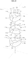
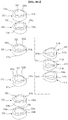
- FIG. 1 is a view illustrating an arm unit and a drive unit according to an embodiment.
- a robot 1 may include, for example, an arm unit 10, and a drive unit 50 to drive the arm unit 10.
- the arm unit 10 may include links 110 arranged in series in a rolling contact manner, and wires 181a, 181b, 182a and 182b penetrating the links 110 to connect the links 110 to one another.
- the wires 181a, 181b, 182a and 182b include a pair of first wires 181a and 181b arranged opposite to each other to realize a tilt motion of the arm unit 10, and a pair of second wires 182a and 182b arranged opposite to each other to realize a pan motion of the arm unit 10.
- the drive unit 50 includes at least one pulley 52 to change paths of the wires 181a, 181b, 182a and 182b, drive plates 54 connected to the wires 181a, 181b, 182a and 182b to adjust tension applied to the wires 181a, 181b, 182a and 182b, and a drive motor (not shown) to drive the drive plates 54.
- the drive plates 54 have an arc shape such that the wires 181a, 181b, 182a and 182b are wound on the drive plates 54.
- the drive plates 54 include a first drive plate 54a that is connected to the first wires 181a and 181b associated with a tilt motion of the arm unit 10 to adjust tension of the first wires 181a and 181b, and a second drive plate 54b that is connected to the second wires 182a and 182b associated with a pan motion of the arm unit 10 to adjust tension of the second wires 182a and 182b.
- the first drive plate 54a and the second drive plate 54b are individually rotated, thereby adjusting tension of the first wires 181a and 181b and the second wires 182a and 182b to realize a tilt motion and a pan motion of the arm unit 10.
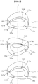
- FIG. 2 is a view illustrating the links making up the arm unit of FIG. 1
- FIG. 3 is a view illustrating the links of FIG. 2 when viewed from a different angle
- FIG. 4 is a side view of FIG. 2
- FIGS. 5A and 5B are views illustrating a tilt motion and a pan motion of the arm unit according to an embodiment.
- each link 110 includes a centrally-hollowed body 112, a pair of first rolling-contact portions 114a and 114b formed by curving a surface of the body 112 in a first direction toward another neighboring link 110 disposed above the link 110, and a pair of second rolling-contact portions 116a and 116b formed by curving a surface of the body 112 in a direction opposite to the first direction.
- the first rolling-contact portions 114a and 114b are longitudinally raised from a part of an upper surface of the body 112, so as to come into contact with another neighboring link 110 disposed above link 110.
- the second rolling-contact portions 116a and 116b are raised from a part of a lower surface of the body 112 in a direction opposite to the raised direction of the first rolling-contact portions 114a and 114b, so as to come into contact with another neighboring link 110 disposed below link 110. That is, the first rolling-contact portions 114a and 114b and the second rolling-contact portions 116a and 116b may be respectively referred to as first convex portions 114a and 114b and second convex portions 116a and 116b.
- the pair of first rolling-contact portions 114a and 114b or the pair of second rolling-contact portions 116a and 116b may be arranged at 180° -rotated positions on the basis of a center axis Lc of the body 112 in a longitudinal direction of the body. That is, in an embodiment, the pair of first rolling-contact portions 114a and 114b or the pair of second rolling-contact portions 116a and 116b may be disposed opposite to each other on the body as illustrated, for example, at FIG. 2 .
- the pair of first rolling-contact portions 114a and 114b may be arranged at 90° - rotated positions with respect to the pair of second rolling-contact portions 116a and 116b on the basis of the center axis Lc in a circumferential direction of the body 112.
- the upper surface of the body 112, on which the first rolling-contact portions 114a and 114b are formed, is provided with first concave portions 115a and 115b connected to the first rolling-contact portions 114a and 114b.
- the lower surface of the body 112, on which the second rolling-contact portions 116a and 116b are formed, is provided with second concave portions 117a and 117b connected to the second rolling-contact portions 116a and 116b.
- the first concave portions 115a and 115b are arranged at 90° -rotated positions with respect to the first rolling-contact portions 114a and 114b on the basis of the center axis Lc in a circumferential direction of the body 112.
- the second concave portions 117a and 117b are arranged at 90° -rotated positions with respect to the second rolling-contact portions 116a and 116b on the basis of the center axis Lc in a circumferential direction of the body 112.
- the first rolling-contact portions 114a and 114b are arranged symmetrically to each other on the basis of an imaginary first division plane F1 containing the center axis Lc
- the first concave portions 115a and 115b are arranged symmetrically to each other on the basis of an imaginary second division plane F2 that contains the center axis Lc and is perpendicular to the first division plane F1, as illustrated at FIG. 2 .
- the pair of first rolling-contact portions 114a and 114b and the pair of second rolling-contact portions 116a and 116b respectively have first through-holes 121a and 121b and second through-holes 122a and 122b for penetration of the first wires 181a and 181b and the second wires 182a and 182b to realize a tilt motion and a pan motion.
- the individual links 110 are sequentially coupled to one another such that each link 110 is rotated by 90° on the basis of the center axis Lc with respect to another neighboring link 110, thereby constituting or articulating the arm unit 10.
- the first wires 181a and 181b and the second wires 182a and 182b respectively penetrate the first through-holes 121a and 121b of one link 110 and the second through-holes 122a and 122b of another neighboring link 110 in sequence.
- each of the first and second rolling-contact portions 114a and 114b and 116a and 116b may be a part of a circle having a predetermined curvature C as illustrated in FIG. 4 .
- the phrase "rolling contact manner" may describe rolling-contact portions rotating with respect to each other while making contact along curvature C to thereby enable relative pivoting of the respective neighboring links 110.
- the first rolling-contact portions 114a and 114b formed at the upper surface of the body 112 of any one link 110 come into rolling contact with the second rolling-contact portions 116a and 116b formed at the lower surface of the body 112 of another link 110 located thereabove, and the second rolling-contact portions 116a and 116b formed at the lower surface of the body 112 of any one link 110 come into rolling contact with the first rolling-contact portions 114a and 114b formed at the upper surface of the body 112 of another link 110 located therebelow.
- the first concave portions 115a and 115b which are connected to the first rolling-contact portions 114a and 114b of any one link 110, are arranged opposite to the second concave portions 117a and 117b, which are connected to the second rolling-contact portions 116a and 116b of another link 110 located thereabove.
- pivoting spaces S1 and S2 are defined to enable relative pivoting of the respective neighboring links 110, as illustrated at FIG. 1 , for example.
- the second concave portions 117a and 117b which are connected to the second rolling-contact portions 116a and 116b of any one link 110, are arranged opposite to the first concave portions 115a and 115b, which are connected to the first rolling-contact portions 114a and 114b of another link 110 located therebelow, defining pivoting spaces S1 and S2.
- an extension length of any one of the first wires 181a and 181b is non-symmetric to a contraction length of the other one during implementation of a tilt motion of the arm unit 10
- an extension length of any one of the second wires 182a and 182b is non-symmetric to a contraction length of the other one during implementation of a pan motion of the arm unit 10. That is, tension applied to the first wires 181a and 181b and the second wires 182a and 182b is proportional to stiffness of the arm unit 10 made up of the plurality of links 100.
- FIGS. 6A , 6B , 7A and 7B are views explaining a relationship between tension applied to the wires and stiffness of the arm unit.
- 'n' represents the number of links 110
- ' ⁇ p ' and ' ⁇ t ' respectively represent angles between the respective neighboring links 110 during a pan motion and during a tilt motion
- ' ⁇ p ' and ' ⁇ t ' respectively represent angles between the links 110 located at distal ends during a pan motion and during a tilt motion
- 'L pl ' and 'L pr ' respectively represent lengths of portions of the second wires 182a and 182b connecting the respective neighboring links 110 to one another
- 'd pl ' and 'd pr ' respectively represent overall lengths of the second wires 182a and 182b.
- the sum of d pl ( ⁇ p , ⁇ t ) and d pr ( ⁇ p , d t ) is not zero. That is, the absolute value of an extension length of any one second wire 182a is different from the absolute value of a contraction length of the other second wire 182b while the arm unit 10 performs a tilt motion or a pan motion. This equally applies to the first wires 181a and 181b.
- stiffness of the arm unit 10 may be changed via adjustment of tension of the first wires 181a and 181b and the second wires 182a and 182b.
- ⁇ ⁇ 0 8 r cos ⁇ + 1 n h 2 T
- tension T applied to the first wires 181a and 181b and the second wires 182a and 182b and stiffness K of the arm unit 10 are proportional to one another, and thus stiffness K of the arm unit 10 may be changed by adjusting tension T of the first wires 181a and 181b and the second wires 182a and 182b.
- the arm unit 10 may be provided with flexibility by reducing stiffness while the arm unit 10 moves to a body part to be operated upon along curved internal organs of a patient, and to increase stiffness of the arm unit 10 so as to endure a load applied to the arm unit 10 while the arm unit 10 performs surgery after reaching the body part to be operated upon, which ensures more efficient implementation of surgery.
- FIGS. 8A to 8C are views illustrating insertion of an anti-slip member through the links constituting the arm unit according to an embodiment.
- the anti-slip member 150 is located between the respective neighboring links 110 to prevent slippage that may occur during pivoting of the respective links 110.
- the anti-slip member 150 has a combined shape of a part of the upper surface and a part of the lower surface of the body 112 of the respective links 110, so as to come into contact at one surface 150a and the other surface 150b thereof with the respective neighboring links 110.
- the anti-slip member 150 may be formed of a material that is different than the links' 110 material, and in particular may be formed of a plastic material or rubber material that is efficacious in anti-slip.
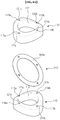
- FIGS. 9A to 9C are views illustrating an arm unit according to another embodiment.
- the respective links 210 of the arm unit 20 further may include toothed portions 214 and 216 to prevent slip during relative pivoting of the links 210.
- the toothed portions 214 and 216 may include a first curvilinear toothed portion 214 and a second curvilinear toothed portion, which are respectively formed at an upper surface and a lower surface of a body 212 of the link 210.
- the first toothed portion 214 and the second toothed portion 216 are formed in a circumferential direction of the upper surface and the lower surface of the body 212.
- the first toothed portion 214 formed at any one of a plurality of links 210 is engaged with the second toothed portion 216 formed at another link 210 located thereabove, which prevents slippage that may occur while the respective neighboring links 110 come into rolling contact with one another to perform pivoting relative to one another.
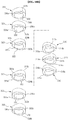
- FIGS. 10A to 10C are views illustrating an arm unit according to another embodiment.
- the arm unit 30 of the present embodiment may include, for example, a first link 310, a second link 320 and a third link 330.
- the second link 320 may be located neighboring an upper surface 312a of the first link 310 to come into rolling contact with the first link 310
- the third link 330 may be located neighboring an upper surface 322a of the second link 320 to come into surface contact with the second link 320.
- the second link 320 and the third link 330 have been described above as being located neighboring the upper surface 312a of the first link 310 and the upper surface 322a of the second link 320 respectively, it will be clearly understood that the second link 320 and the third link 330 may be located respectively neighboring a lower surface 312b of the first link 310 and a lower surface 322b of the second link 320.
- the first link 310 is similar to the above-described link 110 of the arm unit 10, and thus a detailed description thereof is omitted.
- the third link 330 may include a centrally-hollowed body 332, and first flat portion 334a and 334b and second flat portions 336a and 336b formed respectively at an upper surface 332a and a lower surface 332b of the body 332 to come into surface contact with the neighboring second or third link 320 or 330.
- the second link 320 is located between the first link 310 and the third link 330 to connect the first link 310 and the third link 330 to each other.
- the second link 320 includes a centrally-hollowed body 322, third flat portions 324a and 324b formed at a first surface 322a of the body 322, and third rolling-contact portions 326a and 326b formed at a second surface 322b opposite to the first surface 322a.
- the third flat portions 324a and 324b are substantially equal to the first flat portions 334a and 334b or the second flat portions 336a and 336b formed at the third link 330.
- the third rolling-contact portions 326a and 326b are substantially equal to the first rolling-contact portions 314a and 314b or the second rolling-contact portions 316a and 316b formed at the first link 310.
- At least two first links 310 may be arranged neighboring each other to enable a tilt motion and a pan motion of the arm unit 30 via relative pivoting thereof, and at least two third links 330 may be arranged neighboring each other so as to serve as rigid bodies during a tilt motion and a pan motion of the arm unit 30.
- the third links 330 serve as rigid bodies to maintain stiffness of the arm unit 30, and the first links 310 may pivot relative to one another to enable a tilt motion and a pan motion of the arm unit 30.
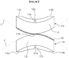
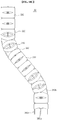
- FIGS. 11A , 11B and 11C are views illustrating an arm unit according to a further embodiment.
- the arm unit 40 may include a first link 410 having symmetric upper and lower portions and a second link 420 having asymmetric upper and lower portions.
- the first link 410 is similar to the above-described link 110 of the arm unit 10, and thus a detailed description thereof is omitted.
- the second link 420 includes a centrally-hollowed body 422, fourth rolling-contact portions 424a and 424b formed at a first surface 422a of the body 422, and fifth rolling-contact portions 426a and 426b formed at a second surface 422b opposite to the first surface 422a.
- the body 422 is asymmetrically configured such that one side extends more than the other side in a pivoting direction of the first link 410 or the second link 420 during a tilt motion or a pan motion of the arm unit 40, which causes a height difference between the fourth rolling-contact portions 424a and 424b.
- the first link 410 and the second link 420 are alternately arranged at 90° -rotated positions relative to each other, causing the arm unit 40 to be initially tilted as during implementation of a tilt motion or a pan motion. This allows the arm unit 40 to perform a tilt motion or a pan motion at a greater angle, and consequently increases a reachable range of the arm unit 40 to a body part to be operated upon, etc.
- an arm unit made up of a plurality of links is adjustable in stiffness via tension adjustment of wires.
Landscapes
- Engineering & Computer Science (AREA)
- Health & Medical Sciences (AREA)
- Surgery (AREA)
- Life Sciences & Earth Sciences (AREA)
- Robotics (AREA)
- Heart & Thoracic Surgery (AREA)
- Nuclear Medicine, Radiotherapy & Molecular Imaging (AREA)
- Biomedical Technology (AREA)
- Medical Informatics (AREA)
- Molecular Biology (AREA)
- Animal Behavior & Ethology (AREA)
- General Health & Medical Sciences (AREA)
- Public Health (AREA)
- Veterinary Medicine (AREA)
- Mechanical Engineering (AREA)
- Manipulator (AREA)
- Transmission Devices (AREA)
- Toys (AREA)
Applications Claiming Priority (2)
| Application Number | Priority Date | Filing Date | Title |
|---|---|---|---|
| KR20120056374 | 2012-05-25 | ||
| KR1020120131721A KR102023906B1 (ko) | 2012-05-25 | 2012-11-20 | 암 유닛 및 이를 포함하는 로봇 |
Publications (2)
| Publication Number | Publication Date |
|---|---|
| EP2666434A1 EP2666434A1 (en) | 2013-11-27 |
| EP2666434B1 true EP2666434B1 (en) | 2018-12-05 |
Family
ID=48625736
Family Applications (1)
| Application Number | Title | Priority Date | Filing Date |
|---|---|---|---|
| EP13169235.2A Active EP2666434B1 (en) | 2012-05-25 | 2013-05-24 | Arm unit and robot having the same |
Country Status (4)
| Country | Link |
|---|---|
| US (1) | US9981392B2 (zh) |
| EP (1) | EP2666434B1 (zh) |
| JP (1) | JP6356390B2 (zh) |
| CN (1) | CN103417298B (zh) |
Families Citing this family (35)
| Publication number | Priority date | Publication date | Assignee | Title |
|---|---|---|---|---|
| KR101405087B1 (ko) * | 2012-04-27 | 2014-06-10 | 한양대학교 에리카산학협력단 | 수술도구용 관절 |
| US9713873B2 (en) * | 2012-05-12 | 2017-07-25 | Massachusetts Institute Of Technology | Continuum style manipulator actuated with phase change media |
| US10624530B2 (en) * | 2013-10-31 | 2020-04-21 | Howard Graham | Flexible structures |
| CN104116528A (zh) * | 2014-07-14 | 2014-10-29 | 上海交通大学 | 基于柔顺连续体机构的内镜手术器械外护套 |
| WO2016063348A1 (ja) * | 2014-10-21 | 2016-04-28 | オリンパス株式会社 | 湾曲機構および軟性医療器具 |
| GB201504843D0 (en) | 2015-03-23 | 2015-05-06 | Rolls Royce Plc | Flexible tools and apparatus for machining objects |
| US11457987B2 (en) * | 2015-05-15 | 2022-10-04 | The Johns Hopkins University | Manipulator device and therapeutic and diagnostic methods |
| CN105034019A (zh) * | 2015-08-21 | 2015-11-11 | 昆山硅步机器人技术有限公司 | 一种柔性机械手臂 |
| CN206154307U (zh) * | 2015-09-06 | 2017-05-10 | 上海科斗电子科技有限公司 | 柔体机械驱动系统 |
| US10035576B1 (en) * | 2015-09-18 | 2018-07-31 | X Development Llc | Flex connection for high altitude balloons |
| CN106113019B (zh) * | 2016-07-22 | 2018-07-10 | 长春理工大学 | 多关节挠性机械手臂 |
| GB2557269B (en) * | 2016-12-02 | 2020-05-06 | Rolls Royce Plc | Hyper redundant robots |
| CN106955161A (zh) * | 2017-03-30 | 2017-07-18 | 微创(上海)医疗机器人有限公司 | 手术机器人用蛇形关节、手术器械及内窥镜 |
| CN107097218B (zh) * | 2017-05-26 | 2023-04-07 | 天津大学 | 一种基于机械锁定的丝牵引变刚度机构 |
| US11097430B2 (en) * | 2017-10-31 | 2021-08-24 | Worcester Polytechnic Institute | Robotic gripper member |
| US11865702B2 (en) | 2017-10-31 | 2024-01-09 | Worcester Polytechnic Institute | Robotic gripper member |
| KR102111684B1 (ko) * | 2017-12-27 | 2020-05-15 | 한국기계연구원 | 강성조절이 가능한 수술용 가이드 어셈블리 및 이를 이용한 수술용 가이드 시스템 |
| US10730179B2 (en) * | 2018-05-29 | 2020-08-04 | General Electric Company | Robotic arm assembly construction |
| CN108942906B (zh) * | 2018-08-01 | 2020-08-28 | 清华大学深圳研究生院 | 柔性机械臂及系统总成 |
| CN112842534B (zh) * | 2018-12-28 | 2024-03-29 | 北京术锐机器人股份有限公司 | 手术工具系统 |
| FR3093510B1 (fr) * | 2019-03-06 | 2021-11-26 | Push4M | Procede et dispositif de mise en tension d’une sangle |
| CN111761572A (zh) * | 2019-04-01 | 2020-10-13 | 中旭智能机器人有限公司 | 用于远端操作的柔性机械臂、柔性机械腕以及包含其的柔性执行机构 |
| KR102128269B1 (ko) | 2019-04-09 | 2020-07-08 | 한국과학기술연구원 | 구름 조인트와 핀 커플링을 이용한 관절 구조체 및 이를 구비한 튜브 삽입형 장치 |
| JP7055766B2 (ja) * | 2019-04-11 | 2022-04-18 | 日本発條株式会社 | 可撓部材 |
| JP7055767B2 (ja) * | 2019-04-11 | 2022-04-18 | 日本発條株式会社 | 可撓部材 |
| KR102245962B1 (ko) * | 2019-05-15 | 2021-04-29 | 한국과학기술연구원 | 구름 조인트와 돌기 부재를 이용한 관절 구조체 및 이를 구비한 튜브 삽입형 장치 |
| CN110900652A (zh) * | 2019-11-27 | 2020-03-24 | 天津大学 | 一种基于海绵的连续体变刚度机械臂 |
| US11865703B2 (en) * | 2019-12-05 | 2024-01-09 | Sanctuary Cognitive Systems Corporation | Flexible mechanical joint |
| CN111230845B (zh) * | 2020-02-24 | 2021-04-20 | 西安交通大学 | 一种拉弯型连续体机器人单元及机器人 |
| CN112790864B (zh) * | 2020-12-30 | 2022-03-08 | 山东大学 | 一种柔性展开臂的参数优化设计方法 |
| CN112976052B (zh) * | 2021-02-26 | 2022-09-30 | 天津大学 | 一种镜像控制机械臂单元 |
| CN113183144A (zh) * | 2021-05-13 | 2021-07-30 | 上海大学 | 一种线缆驱动的滚动关节连续体机械臂 |
| JP2023028474A (ja) * | 2021-08-19 | 2023-03-03 | キヤノン株式会社 | 連続体ロボットの制御システム及びその制御方法 |
| CN113814959B (zh) * | 2021-09-02 | 2023-07-07 | 浙江大学 | 一种负向角度补偿的柔性机械臂 |
| CN114474147A (zh) * | 2022-01-30 | 2022-05-13 | 四川大学 | 可实现快速装配的柔性臂机构及gis检修机器人 |
Citations (2)
| Publication number | Priority date | Publication date | Assignee | Title |
|---|---|---|---|---|
| US4393728A (en) * | 1979-03-16 | 1983-07-19 | Robotgruppen Hb | Flexible arm, particularly a robot arm |
| US20100076266A1 (en) * | 2003-04-01 | 2010-03-25 | Boston Scientific Scimed, Inc | Articulation joint for video endoscope |
Family Cites Families (18)
| Publication number | Priority date | Publication date | Assignee | Title |
|---|---|---|---|---|
| US4494417A (en) * | 1979-03-16 | 1985-01-22 | Robotgruppen Hb | Flexible arm, particularly a robot arm |
| SE436175B (sv) * | 1982-07-05 | 1984-11-19 | Robotgruppen Hb | Anordning for vridstyv forbindelse av i en robotarm eller liknande ingaende element |
| JPS5924004U (ja) * | 1982-08-06 | 1984-02-15 | 株式会社町田製作所 | 内視鏡のアングル部を構成する節輪 |
| JP3219503B2 (ja) * | 1992-12-02 | 2001-10-15 | 三菱重工業株式会社 | 方向変換式フレキシブルアーム |
| US5456568A (en) * | 1993-12-27 | 1995-10-10 | Kirby; Jeffrey R. | Arm mechanism |
| JP2000193893A (ja) * | 1998-12-28 | 2000-07-14 | Suzuki Motor Corp | 検査用挿入管の屈曲装置 |
| GB0114406D0 (en) * | 2001-06-13 | 2001-08-08 | Oliver Crispin Consulting Ltd | Improvements in and relating to robotic arms |
| US20060178556A1 (en) * | 2001-06-29 | 2006-08-10 | Intuitive Surgical, Inc. | Articulate and swapable endoscope for a surgical robot |
| US20060199999A1 (en) * | 2001-06-29 | 2006-09-07 | Intuitive Surgical Inc. | Cardiac tissue ablation instrument with flexible wrist |
| US6817974B2 (en) | 2001-06-29 | 2004-11-16 | Intuitive Surgical, Inc. | Surgical tool having positively positionable tendon-actuated multi-disk wrist joint |
| US8118732B2 (en) * | 2003-04-01 | 2012-02-21 | Boston Scientific Scimed, Inc. | Force feedback control system for video endoscope |
| US7090637B2 (en) | 2003-05-23 | 2006-08-15 | Novare Surgical Systems, Inc. | Articulating mechanism for remote manipulation of a surgical or diagnostic tool |
| US9962066B2 (en) * | 2005-12-30 | 2018-05-08 | Intuitive Surgical Operations, Inc. | Methods and apparatus to shape flexible entry guides for minimally invasive surgery |
| GB0600170D0 (en) * | 2006-01-06 | 2006-02-15 | Oliver Crispin Robotics Ltd | Improvements in and relating to robotic arms |
| EP2067450A1 (en) | 2006-09-28 | 2009-06-10 | Waseda University | Sensing system employing medical manipulator and pressing force measuring device and its program |
| WO2010140844A2 (ko) * | 2009-06-05 | 2010-12-09 | 주식회사 이턴 | 수술용 인스트루먼트 |
| KR20110036800A (ko) | 2011-02-25 | 2011-04-11 | 주식회사 이턴 | 수술용 인스트루먼트 |
| US20120253326A1 (en) * | 2011-03-29 | 2012-10-04 | Tyco Healthcare Group Lp | Articulation of Laparoscopic Instrument |
-
2013
- 2013-05-17 CN CN201310183103.1A patent/CN103417298B/zh active Active
- 2013-05-21 JP JP2013107170A patent/JP6356390B2/ja active Active
- 2013-05-21 US US13/898,888 patent/US9981392B2/en active Active
- 2013-05-24 EP EP13169235.2A patent/EP2666434B1/en active Active
Patent Citations (2)
| Publication number | Priority date | Publication date | Assignee | Title |
|---|---|---|---|---|
| US4393728A (en) * | 1979-03-16 | 1983-07-19 | Robotgruppen Hb | Flexible arm, particularly a robot arm |
| US20100076266A1 (en) * | 2003-04-01 | 2010-03-25 | Boston Scientific Scimed, Inc | Articulation joint for video endoscope |
Also Published As
| Publication number | Publication date |
|---|---|
| US9981392B2 (en) | 2018-05-29 |
| JP2013244595A (ja) | 2013-12-09 |
| EP2666434A1 (en) | 2013-11-27 |
| CN103417298B (zh) | 2017-10-10 |
| US20130312564A1 (en) | 2013-11-28 |
| JP6356390B2 (ja) | 2018-07-11 |
| CN103417298A (zh) | 2013-12-04 |
Similar Documents
| Publication | Publication Date | Title |
|---|---|---|
| EP2666434B1 (en) | Arm unit and robot having the same | |
| US20190150905A1 (en) | Minimally invasive surgical instrument having articulation immobilising structure | |
| US9585641B2 (en) | Flexible wrist for surgical tool | |
| JP5937107B2 (ja) | トルク伝達のための関節式継手 | |
| US20130281924A1 (en) | Segmented instrument shaft with antirotation features | |
| US20150314451A1 (en) | Tool grip calibration for robotic surgery | |
| KR20180025934A (ko) | 로봇 암의 관절 및 외과 기기 | |
| US20110251599A1 (en) | Deflectable instrument shafts | |
| KR102023906B1 (ko) | 암 유닛 및 이를 포함하는 로봇 | |
| US20140094782A1 (en) | Minimally invasive surgical instrument having shaft including internal torque-transmission member | |
| US20150148839A1 (en) | Minimally invasive surgery tool having variable bend | |
| KR20130131276A (ko) | 개선된 관절부를 갖는 최소 침습 수술 기구 |
Legal Events
| Date | Code | Title | Description |
|---|---|---|---|
| PUAI | Public reference made under article 153(3) epc to a published international application that has entered the european phase |
Free format text: ORIGINAL CODE: 0009012 |
|
| AK | Designated contracting states |
Kind code of ref document: A1 Designated state(s): AL AT BE BG CH CY CZ DE DK EE ES FI FR GB GR HR HU IE IS IT LI LT LU LV MC MK MT NL NO PL PT RO RS SE SI SK SM TR |
|
| AX | Request for extension of the european patent |
Extension state: BA ME |
|
| 17P | Request for examination filed |
Effective date: 20140331 |
|
| RBV | Designated contracting states (corrected) |
Designated state(s): AL AT BE BG CH CY CZ DE DK EE ES FI FR GB GR HR HU IE IS IT LI LT LU LV MC MK MT NL NO PL PT RO RS SE SI SK SM TR |
|
| STAA | Information on the status of an ep patent application or granted ep patent |
Free format text: STATUS: EXAMINATION IS IN PROGRESS |
|
| 17Q | First examination report despatched |
Effective date: 20171023 |
|
| REG | Reference to a national code |
Ref country code: DE Ref legal event code: R079 Ref document number: 602013047685 Country of ref document: DE Free format text: PREVIOUS MAIN CLASS: A61B0019000000 Ipc: A61B0034000000 |
|
| GRAP | Despatch of communication of intention to grant a patent |
Free format text: ORIGINAL CODE: EPIDOSNIGR1 |
|
| STAA | Information on the status of an ep patent application or granted ep patent |
Free format text: STATUS: GRANT OF PATENT IS INTENDED |
|
| RIC1 | Information provided on ipc code assigned before grant |
Ipc: A61B 34/00 20160101AFI20180608BHEP Ipc: A61B 34/30 20160101ALN20180608BHEP |
|
| INTG | Intention to grant announced |
Effective date: 20180629 |
|
| RIN1 | Information on inventor provided before grant (corrected) |
Inventor name: KIM, YONG JAE Inventor name: IAGNEMMA, KARL Inventor name: CHENG, SHAN BAO Inventor name: KIM, SANG BAE |
|
| GRAS | Grant fee paid |
Free format text: ORIGINAL CODE: EPIDOSNIGR3 |
|
| GRAA | (expected) grant |
Free format text: ORIGINAL CODE: 0009210 |
|
| GRAA | (expected) grant |
Free format text: ORIGINAL CODE: 0009210 |
|
| STAA | Information on the status of an ep patent application or granted ep patent |
Free format text: STATUS: THE PATENT HAS BEEN GRANTED |
|
| AK | Designated contracting states |
Kind code of ref document: B1 Designated state(s): AL AT BE BG CH CY CZ DE DK EE ES FI FR GB GR HR HU IE IS IT LI LT LU LV MC MK MT NL NO PL PT RO RS SE SI SK SM TR |
|
| REG | Reference to a national code |
Ref country code: GB Ref legal event code: FG4D |
|
| REG | Reference to a national code |
Ref country code: CH Ref legal event code: EP |
|
| REG | Reference to a national code |
Ref country code: AT Ref legal event code: REF Ref document number: 1072099 Country of ref document: AT Kind code of ref document: T Effective date: 20181215 |
|
| REG | Reference to a national code |
Ref country code: IE Ref legal event code: FG4D |
|
| REG | Reference to a national code |
Ref country code: DE Ref legal event code: R096 Ref document number: 602013047685 Country of ref document: DE |
|
| REG | Reference to a national code |
Ref country code: NL Ref legal event code: MP Effective date: 20181205 |
|
| REG | Reference to a national code |
Ref country code: AT Ref legal event code: MK05 Ref document number: 1072099 Country of ref document: AT Kind code of ref document: T Effective date: 20181205 |
|
| REG | Reference to a national code |
Ref country code: LT Ref legal event code: MG4D |
|
| PG25 | Lapsed in a contracting state [announced via postgrant information from national office to epo] |
Ref country code: FI Free format text: LAPSE BECAUSE OF FAILURE TO SUBMIT A TRANSLATION OF THE DESCRIPTION OR TO PAY THE FEE WITHIN THE PRESCRIBED TIME-LIMIT Effective date: 20181205 Ref country code: LV Free format text: LAPSE BECAUSE OF FAILURE TO SUBMIT A TRANSLATION OF THE DESCRIPTION OR TO PAY THE FEE WITHIN THE PRESCRIBED TIME-LIMIT Effective date: 20181205 Ref country code: AT Free format text: LAPSE BECAUSE OF FAILURE TO SUBMIT A TRANSLATION OF THE DESCRIPTION OR TO PAY THE FEE WITHIN THE PRESCRIBED TIME-LIMIT Effective date: 20181205 Ref country code: HR Free format text: LAPSE BECAUSE OF FAILURE TO SUBMIT A TRANSLATION OF THE DESCRIPTION OR TO PAY THE FEE WITHIN THE PRESCRIBED TIME-LIMIT Effective date: 20181205 Ref country code: BG Free format text: LAPSE BECAUSE OF FAILURE TO SUBMIT A TRANSLATION OF THE DESCRIPTION OR TO PAY THE FEE WITHIN THE PRESCRIBED TIME-LIMIT Effective date: 20190305 Ref country code: ES Free format text: LAPSE BECAUSE OF FAILURE TO SUBMIT A TRANSLATION OF THE DESCRIPTION OR TO PAY THE FEE WITHIN THE PRESCRIBED TIME-LIMIT Effective date: 20181205 Ref country code: LT Free format text: LAPSE BECAUSE OF FAILURE TO SUBMIT A TRANSLATION OF THE DESCRIPTION OR TO PAY THE FEE WITHIN THE PRESCRIBED TIME-LIMIT Effective date: 20181205 Ref country code: NO Free format text: LAPSE BECAUSE OF FAILURE TO SUBMIT A TRANSLATION OF THE DESCRIPTION OR TO PAY THE FEE WITHIN THE PRESCRIBED TIME-LIMIT Effective date: 20190305 |
|
| PG25 | Lapsed in a contracting state [announced via postgrant information from national office to epo] |
Ref country code: AL Free format text: LAPSE BECAUSE OF FAILURE TO SUBMIT A TRANSLATION OF THE DESCRIPTION OR TO PAY THE FEE WITHIN THE PRESCRIBED TIME-LIMIT Effective date: 20181205 Ref country code: GR Free format text: LAPSE BECAUSE OF FAILURE TO SUBMIT A TRANSLATION OF THE DESCRIPTION OR TO PAY THE FEE WITHIN THE PRESCRIBED TIME-LIMIT Effective date: 20190306 Ref country code: RS Free format text: LAPSE BECAUSE OF FAILURE TO SUBMIT A TRANSLATION OF THE DESCRIPTION OR TO PAY THE FEE WITHIN THE PRESCRIBED TIME-LIMIT Effective date: 20181205 Ref country code: SE Free format text: LAPSE BECAUSE OF FAILURE TO SUBMIT A TRANSLATION OF THE DESCRIPTION OR TO PAY THE FEE WITHIN THE PRESCRIBED TIME-LIMIT Effective date: 20181205 |
|
| PG25 | Lapsed in a contracting state [announced via postgrant information from national office to epo] |
Ref country code: NL Free format text: LAPSE BECAUSE OF FAILURE TO SUBMIT A TRANSLATION OF THE DESCRIPTION OR TO PAY THE FEE WITHIN THE PRESCRIBED TIME-LIMIT Effective date: 20181205 |
|
| PG25 | Lapsed in a contracting state [announced via postgrant information from national office to epo] |
Ref country code: CZ Free format text: LAPSE BECAUSE OF FAILURE TO SUBMIT A TRANSLATION OF THE DESCRIPTION OR TO PAY THE FEE WITHIN THE PRESCRIBED TIME-LIMIT Effective date: 20181205 Ref country code: IT Free format text: LAPSE BECAUSE OF FAILURE TO SUBMIT A TRANSLATION OF THE DESCRIPTION OR TO PAY THE FEE WITHIN THE PRESCRIBED TIME-LIMIT Effective date: 20181205 Ref country code: PT Free format text: LAPSE BECAUSE OF FAILURE TO SUBMIT A TRANSLATION OF THE DESCRIPTION OR TO PAY THE FEE WITHIN THE PRESCRIBED TIME-LIMIT Effective date: 20190405 Ref country code: PL Free format text: LAPSE BECAUSE OF FAILURE TO SUBMIT A TRANSLATION OF THE DESCRIPTION OR TO PAY THE FEE WITHIN THE PRESCRIBED TIME-LIMIT Effective date: 20181205 |
|
| PG25 | Lapsed in a contracting state [announced via postgrant information from national office to epo] |
Ref country code: SM Free format text: LAPSE BECAUSE OF FAILURE TO SUBMIT A TRANSLATION OF THE DESCRIPTION OR TO PAY THE FEE WITHIN THE PRESCRIBED TIME-LIMIT Effective date: 20181205 Ref country code: EE Free format text: LAPSE BECAUSE OF FAILURE TO SUBMIT A TRANSLATION OF THE DESCRIPTION OR TO PAY THE FEE WITHIN THE PRESCRIBED TIME-LIMIT Effective date: 20181205 Ref country code: SK Free format text: LAPSE BECAUSE OF FAILURE TO SUBMIT A TRANSLATION OF THE DESCRIPTION OR TO PAY THE FEE WITHIN THE PRESCRIBED TIME-LIMIT Effective date: 20181205 Ref country code: IS Free format text: LAPSE BECAUSE OF FAILURE TO SUBMIT A TRANSLATION OF THE DESCRIPTION OR TO PAY THE FEE WITHIN THE PRESCRIBED TIME-LIMIT Effective date: 20190405 Ref country code: RO Free format text: LAPSE BECAUSE OF FAILURE TO SUBMIT A TRANSLATION OF THE DESCRIPTION OR TO PAY THE FEE WITHIN THE PRESCRIBED TIME-LIMIT Effective date: 20181205 |
|
| REG | Reference to a national code |
Ref country code: DE Ref legal event code: R097 Ref document number: 602013047685 Country of ref document: DE |
|
| PLBE | No opposition filed within time limit |
Free format text: ORIGINAL CODE: 0009261 |
|
| STAA | Information on the status of an ep patent application or granted ep patent |
Free format text: STATUS: NO OPPOSITION FILED WITHIN TIME LIMIT |
|
| PG25 | Lapsed in a contracting state [announced via postgrant information from national office to epo] |
Ref country code: SI Free format text: LAPSE BECAUSE OF FAILURE TO SUBMIT A TRANSLATION OF THE DESCRIPTION OR TO PAY THE FEE WITHIN THE PRESCRIBED TIME-LIMIT Effective date: 20181205 Ref country code: DK Free format text: LAPSE BECAUSE OF FAILURE TO SUBMIT A TRANSLATION OF THE DESCRIPTION OR TO PAY THE FEE WITHIN THE PRESCRIBED TIME-LIMIT Effective date: 20181205 |
|
| 26N | No opposition filed |
Effective date: 20190906 |
|
| REG | Reference to a national code |
Ref country code: CH Ref legal event code: PL |
|
| PG25 | Lapsed in a contracting state [announced via postgrant information from national office to epo] |
Ref country code: LI Free format text: LAPSE BECAUSE OF NON-PAYMENT OF DUE FEES Effective date: 20190531 Ref country code: MC Free format text: LAPSE BECAUSE OF FAILURE TO SUBMIT A TRANSLATION OF THE DESCRIPTION OR TO PAY THE FEE WITHIN THE PRESCRIBED TIME-LIMIT Effective date: 20181205 Ref country code: CH Free format text: LAPSE BECAUSE OF NON-PAYMENT OF DUE FEES Effective date: 20190531 |
|
| REG | Reference to a national code |
Ref country code: BE Ref legal event code: MM Effective date: 20190531 |
|
| PG25 | Lapsed in a contracting state [announced via postgrant information from national office to epo] |
Ref country code: LU Free format text: LAPSE BECAUSE OF NON-PAYMENT OF DUE FEES Effective date: 20190524 |
|
| PG25 | Lapsed in a contracting state [announced via postgrant information from national office to epo] |
Ref country code: TR Free format text: LAPSE BECAUSE OF FAILURE TO SUBMIT A TRANSLATION OF THE DESCRIPTION OR TO PAY THE FEE WITHIN THE PRESCRIBED TIME-LIMIT Effective date: 20181205 |
|
| PG25 | Lapsed in a contracting state [announced via postgrant information from national office to epo] |
Ref country code: IE Free format text: LAPSE BECAUSE OF NON-PAYMENT OF DUE FEES Effective date: 20190524 |
|
| PG25 | Lapsed in a contracting state [announced via postgrant information from national office to epo] |
Ref country code: BE Free format text: LAPSE BECAUSE OF NON-PAYMENT OF DUE FEES Effective date: 20190531 |
|
| PG25 | Lapsed in a contracting state [announced via postgrant information from national office to epo] |
Ref country code: CY Free format text: LAPSE BECAUSE OF FAILURE TO SUBMIT A TRANSLATION OF THE DESCRIPTION OR TO PAY THE FEE WITHIN THE PRESCRIBED TIME-LIMIT Effective date: 20181205 |
|
| PG25 | Lapsed in a contracting state [announced via postgrant information from national office to epo] |
Ref country code: HU Free format text: LAPSE BECAUSE OF FAILURE TO SUBMIT A TRANSLATION OF THE DESCRIPTION OR TO PAY THE FEE WITHIN THE PRESCRIBED TIME-LIMIT; INVALID AB INITIO Effective date: 20130524 Ref country code: MT Free format text: LAPSE BECAUSE OF FAILURE TO SUBMIT A TRANSLATION OF THE DESCRIPTION OR TO PAY THE FEE WITHIN THE PRESCRIBED TIME-LIMIT Effective date: 20181205 |
|
| PG25 | Lapsed in a contracting state [announced via postgrant information from national office to epo] |
Ref country code: MK Free format text: LAPSE BECAUSE OF FAILURE TO SUBMIT A TRANSLATION OF THE DESCRIPTION OR TO PAY THE FEE WITHIN THE PRESCRIBED TIME-LIMIT Effective date: 20181205 |
|
| PGFP | Annual fee paid to national office [announced via postgrant information from national office to epo] |
Ref country code: FR Payment date: 20230420 Year of fee payment: 11 Ref country code: DE Payment date: 20230420 Year of fee payment: 11 |
|
| PGFP | Annual fee paid to national office [announced via postgrant information from national office to epo] |
Ref country code: GB Payment date: 20230420 Year of fee payment: 11 |